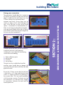
1
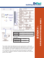
building the future
Rainwater Harvesting System
Installation and Operation Manual
PVC-UE Roofline,
Window &
Cladding Systems
Rainwater
Systems
Soil & Waste
Systems
Underground
Drainage
Systems
MDPE
Systems
Hot & Cold
Plumbing
Systems
building the future
SECTION 1 : Introduction
SECTION 2 : Groundwork and Installation of tank
SECTION 3 : Installation of mechanical works
SECTION 4 : Installation of electrical works
SECTION 5 : Pipework and labelling
SECTION 6 : Optional extras
SECTION 7 : Running the system and troubleshooting
www.floplast.co.uk
CONTENTS
/products/rainwater-systems/stormsaver
Rainwater Harvesting System
building the future
INTRODUCTION TO
Please read these instructions carefully before installing the
system.
The StormSaver rainwater recovery system requires specialist installation. If you
do not have relevant experience, please contact a contractor who does, or call
FloPlast for further advice on 01795 431731.
WARNING
Failure to correctly install the system will invalidate the warranty! It is the
responsibility of the installer to comply with the Water Supply (Water Fittings)
Regulations 1999.
Standards, Guidelines & Certifications
The StormSaver System complies with the standard for rainwater harvesting
systems, BS8515-2009 and complies with the Water Supply (Water Fittings)
Regulations 1999 which confirms the “independent inflow” required for reliable
separation of service water and the potable water connection which is
integrated in the system. The voltage is supplied through a switching power
supply. All external components of the system operate using safe low voltage
technology. The model brought to market incorporates design, construction and
materials which satisfy the basic safety and health requirements of the EC
Directive for Machinery. This declaration becomes invalid if any modifications
are made to the equipment without our approval. In particular this equipment
meets the requirements of the EU directives:
EC Directive for Machinery (89/392/EWG) version 91/368/EWG
EC Low Voltage Directive (73/23/EWG) EC Directive for Electromagnetic
Compatibility (89/336/EWG) version 93/31/EWG
The CE mark confirms the compliance of the equipment with the above
directives.
SECTION 1 :
This installation manual contains important information, which must be
observed during installation. It is imperative that this manual is read and
understood by those involved with the professional installation of the system.
This manual should be kept on site during installation of the system for easy
access and reference. For additional copies please download from our
website: www.floplast.co.uk or contact 01795 431731.
INTRODUCTION
Thank you for your purchase of the StormSaver system from FloPlast, designed
for rainwater harvesting in family homes.
building the future
l
Health and Safety at work Act
Construction (Design Management) Regulations
The Building Regulations
Water Supply (Water Fittings) Regulations 1999
The IEE Wiring Regulations for Electrical installations 17Edition
Regulations under the Electricity Act
Control of Substances Hazardous to Health Regulations
British Standards-BS8515
The Chartered Institution of Building Services Engineers Guides, codes
of practice and commissioning codes.
Water Regulations Advisory Scheme Information and guidance Note
No 9-02-05 marking and identification of pipe-work
Installation standards
All works to be carried out in accordance with the requirements of the Institute
of Electrical Engineers, The Chartered Institute of Building Service Engineers,
The British Standards Institute, Building Regulations and current good working
practices. If there are any queries regarding the rainwater system please
contact FloPlast Tel: 01795 431731.
Safety instructions
The installation instructions and user manual must be read carefully before
installing the equipment. The instructions given here must be adhered to
precisely otherwise all warranty claims will become invalid. The operator of the
equipment is responsible for adhering to the safety and installation conditions.
Only the original packaging, which is designed for transporting, is to be used
when moving the equipment. The emergency overflow must always be
connected.
As a safety precaution (in case of improper operation, dry running etc.) the
equipment will automatically shut off after running continuously for more than 2
hours (the display will flash). After such an event the equipment can be
switched on again by disconnecting and reconnecting the plug in the electrical
socket or by switching the isolator on and off at the fused spur. The equipment
is not designed for continuous operation! Installations on a mains water pipe
network may only be carried out by certified technicians.
INTRODUCTION
l
l
l
l
l
l
l
l
l
SECTION 1 :
Compliance with current legislation
Those installing the StormSaver system should be conversant and compliant with
all current legislation and all relevant documentation pertinent to the rainwater
harvesting installation. The following list can be used for guidance and is not a
definitive list to those installing the StormSaver rainwater harvesting system.
building the future
l
l
l
Check the goods for complete content and damage on receipt.
Any damage is the responsibility of the carrier.
Register any claim with them immediately
A report must be made within three working days from date of delivery
of any missing or damaged items. FloPlast cannot accept responsibility
for missing or damaged items if not reported IN WRITING immediately.
Please contact your FloPlast Representative before returning any goods.
INTRODUCTION
Damage in transit
Stormsaver products are carefully checked and tested before dispatch, however
the risk of damage during transit cannot be guaranteed.
SECTION 1 :
Delivery
The StormSaver system components may be delivered to site by various sources
- carrier services or haulage distributors. Large equipment will be
delivered by haulage distributors (such as the storage tank).
FloPlast will endeavor, where possible, to deliver components to site at suitable
times – HOWEVER THIS MAY NOT ALWAYS BE POSSIBLE. Should equipment
arrive either early or late FloPlast cannot be responsible for delivery times.
Due to the nature of the product, the storage tank and system components may
not necessarily arrive together. The customer or appointed contractor is
responsible for unloading and securing the tank and equipment on site. The
storage tank will be offloaded to the nearest hardstanding by the site
contractor. A fee may be chargeable if goods are not accepted by site, if there
is a delay in offloading or for goods returned without prior acceptance in
writing from FloPlast.
building the future
GROUNDWORK AND INSTALLATION OF TANK
Vehicle washing
Landscape
watering and
sprinkler
Toilet
Garden watering
Domestic laundry
Rainwater should not be used for drinking or connected to applications where
the water could accidently be ingested.
Equipment included with tank
l Shallow dig tank with integral filter and inlet calmer
l 235mm turret and pedestrian duty manhole cover
l Low level float switch fitted to bracket
l 20m of ½" suction hose
l Sump
l Boosted floating suction filter kit
GROUNDWORK & INSTALLATION OF TANK
The underground tank stores the rainwater collected from the roof until it is
required for use. The rainwater flows to the tank through sealed downpipes. On
entry to the tank rainwater passes through an integral leaf filter which removes
leaves and debris direct to an overflow. The water enters the main storage tank
area through an inlet calmer to avoid stirring up any sediment which may have
settled on the tank base. A floating suction filter sits just below the water surface
suspended on a float so, when called for, the water drawn out the tank is not
from the surface where pollen or dust may have settled. The floating suction
filter ensures another level of filtering before the water enters the pipework to
the following uses:
SECTION 2 :
Shallow Dig Installation
building the future
d
>2d
SECTION 2 :
This graph demonstrates the maximum
suction hose run length versus the
maximum tank base depth as measured from
the base of the control panel processor unit.
The longer the run of the suction hose, the
shallower the base of the tank must be, and
the same is true in reverse.
A – represents the DEPTH from the base of
the processor unit to the base of the tank
B – represents the LENGTH of the suction
hose run from the control unit to the boosted
suction filter, 150mm from the base of the
tank.
The installation must fall within parameters
above the line on the graph. Installation
which falls within parameters below the line
may result in pressure problems and will not
be covered by warranty.
b
a
Existing pipelines, pipes, vegetation as well
as other specifics must be considered, so that
damage or hazards will be avoided.
Installing the tank
Excavate a hole suitable for the size of your
tank (see next step for sizing your
excavation). Ensure the hole is in a suitable
location as outlined above. Include a
channel for the laying and connection of your
pipework and 110mm service duct. Shore up
the sides of your excavation.
Check tank size and excavate hole
GROUNDWORK & INSTALLATION OF TANK
Where to locate the tank
The tank must be located in a place where
the distance from the edge of the
excavation to the edge of the foundation, is
at least double the difference in depth, from
the base of the foundations to the base of the
excavations. The red dotted line represents
the line the tank excavation must not cross.
building the future
>200mm
>200mm
>200mm
>200mm
>200mm
>100mm
>100mm
Carefully lower the tank into the excavation.
Install and connect up all pipework,
including the service duct for the floating
suction hose and cabling.
3
1.
2.
3.
4.
4
Water collection point
Inlet to tank
Overflow
Service duct
2
1
The tank must be installed level and the
overflow pipe should have a deeper fall
away from the tank than the fall from the feed
pipe to the tank.
Ensure the 110mm service duct for the hose
is laid with a >1% slope and that the hose
within it is taught to prevent air gathering in
the suction hose. This can cause problems
with the pumps running. The hose must be
one continuous run, free from kinks, tangles
or connections, between the tank and the
Service duct slope
control panel unit.
>1%
SECTION 2 :
Min 400mm up to max
800mm with extention turret
400<800mm
GROUNDWORK & INSTALLATION OF TANK
>200mm
>200mm
>200mm
Sizing your excavation
The excavation should allow for a minimum
of 200mm surround to all sides and 500mm
depth in addition to the tank dimensions. Lay
100mm sand on the excavation base,
compact and level. Ensure there are no
stones or edges which could damage the
tank. If the tank has a sump, ensure extra
space is excavated to accommodate this.
Note. If you have purchased the extended
turret the overall depth of the hole will be at
most 900mm more than the tanks height but
the turret can be trimmed to fit.
Fit the relevant manhole covers for the area –
standard supply is pedestrian duty. Ensure
these are fitted prior to backfill to avoid
debris entering the tank. Any debris must be
removed prior to the system being used as
this can affect the systems function. Begin
filling the hole with type 1 aggregate or
sand, avoid filling materials with sharp
Fit turret
edged particles.
100mm
100mm
100mm
100mm
100mm
100mm
100mm
100mm
100mm
This area represents the column supports
Compact every 100mm
Ensure that the top of the tank is covered with
at least 100mm of the filling material before
filling the remaining (minimum) 400/800mm
of the hole, bringing it up to ground level,
with a material of choice suitable for the
location of the tank.
Complete tank burial
Completing the tank installation
Ensure any gaps at the point of the ducting
entering the building are sealed using
expanding foam or wall bush to prevent
odour or drafts entering the building.
Seal with
expanding
foam
SECTION 2 :
Top soil, clay, loam and other types of
cohesive soils and materials with sharp edges
are not suitable filling materials. Carefully
backfill type 1 aggregate to all sides and up
to at least 100mm above the top of the tank,
compacting at every 100mm interval. It is
also important to compact the material down
into the column supports in the tank.
GROUNDWORK & INSTALLATION OF TANK
building the future
building the future
Sealed gully
Run all downpipes into sealed gullies or pipework at ground level so that
rainwater from the roof area only and not groundwater can enter the tank.
Stormsaver recommend that a universal rainwater adaptor (D96 available from
www.floplast.co.uk) is used.
GROUNDWORK & INSTALLATION OF TANK
Open gully
Open or grated gullies (such as the one shown) are not to be used as they allow
surface water and other unwanted liquids, debris or contamination to enter the
rainwater storage tank.
SECTION 2 :
D96
building the future
INSTALLATION OF MECHANICAL WORKS
The regulations state that the rainwater should be supplied in black and green
or black pipework or marked with labels, different to that supplying mains
water supply. This is to ensure that pipework is clearly identifiable and avoid
cross contamination of the two supplies. Blue pipework must be used for the
rainwater installation.
Appropriate insulation must be applied to all pipework with the StormSaver
rainwater recovery system to prevent freezing or warming (not supplied).
It is the responsibility of the installer to ensure that all pipes and water fittings
are clearly identified using approved StormSaver labels, this is essential to
prevent confusion over the source of supply at any later date (available as an
option).
An operating pressure of 2.8 - 3.5 bar is ideal for most conditions and it is the
normal operating pressure within the system.
Warning: if the unit and pressure switch is not set up correctly and the pump
does not stop the pressure can rise to 10 Bar. Please contact FloPlast if you
require further advice
WARNING : 10 Bar is the maximum pump pressure!
IMPORTANT NOTE: The floating suction filter kit and sensors should not be
installed until all works have been completed on site which could produce
cement based or other contaminating debris getting into the tank.
The tank should be cleaned after its installation and before installing the floating
suction filter. Failure to do so can result in blockage of the suction filter which
can damage the pump, leaving the building with no rainwater supply.
SECTION 3 :
All materials used within the installation must be non-corrosive and suitable for
construction, operation, and maintenance including all chemicals, disinfection
agents and all materials in contact with equipment. The installation should meet
standards set by WRAS Water Supply (Water Fittings) Regulations 1999.
INSTALLATION OF MECHANICAL WORKS
WARNING! Please read these instructions carefully before
installing the control panel.
The StormSaver rainwater harvesting system requires professional installation.
A competent plumber should carry out all plumbing works. If you do not have
relevant experience, please contact an installer who does, or call FloPlast for
further advice.
Equipment included with panel
1. Control Unit
1
2. Mainswater connection set
(flexible hose and shut off valve)
3
3. Pressure vessel kit (should be set
at 1.6 bar)
4. Wall fixings for control unit
2
5. Pipe bracket (to support pressure
vessel on wall)
5
4
INSTALLATION OF MECHANICAL WORKS
The StormSaver control panel is the central hub of the system. All the rainwater
must pass through here on its way to the points of use. The control panel is the
place where all the different pipes and hoses connect up, and should be
considered when choosing its location within the building. The unit comprises of
the pump, a small water storage tank, a pressure vessel and the electrical control
panel which enables the whole system to function and includes the display panel.
SECTION 3 :
building the future
building the future
Mechanical works within tank
The control panel unit is supplied with a
submersible pump kit, as it is critical that the
system meets the requirements explained on
the next page.
2
1
7
3
4
Non return valve with hose attachment
Waterproof electrical junction box
Jubilee clips
Hose attachment
Boosted submersible pump
Stainless steel lifting rope and L bracket
Float
6
5
Tank Size
Pipe
Length
to leave
1500
L
3000
L
1M
1M
5000
L
SECTION 3 :
Use a continuous length of suction hose
through the service duct into the tank. Ensure
it is pulled taught, lying flat in the duct and
free of bends. Cut the suction hose to leave
the required amount (see table) dangling into
the tank.
7500
L
1.5 M 1.5 M
Within the tank connect the float to the
boosted submersible pump and then connect
the boosted submersible pump to the suction
hose as shown, using the supplied non return
and hose attachment. Ensure the seals are
tight!
Fix the L-shaped steel bracket to the lip
around the tank access hole. Make sure it is
positioned above the service duct (as shown).
Stainless steal rope fixed to:
L bracket
Float
Attach the provided steel rope to the L
shaped bracket and through the loop on the
top of the float.
Pi
pe
le
ng
th
to
le
av
e
INSTALLATION OF MECHANICAL WORKS
1.
2.
3.
4.
5.
6.
7.
building the future
SECTION 3 :
Do not mount the unit over a sink or water
outlet as the control panel unit contains mains
electric voltage.
This graph demonstrates the maximum
suction hose run length versus the maximum
tank base depth as measured from the base
of the control panel processor unit. The
longer the run of the suction hose, the
shallower the base of the tank must be, and
the same is true in reverse.
A – represents the DEPTH from the base of
the processor unit to the base of the tank
B – represents the LENGTH of the suction
hose run from the control unit to the boosted
suction filter, 150mm from the base of the
tank.
The installation must fall within the
parameters above the line on the graph.
Installation which falls within the parameters
below the line may result in pressure
problems and will not be covered by
warranty.
b
a
INSTALLATION OF MECHANICAL WORKS
Where to locate the unit
The control panel unit is NOT weatherproof
and must not be exposed to the elements. The
unit should be located within the building.
Extremes in temperatures should be avoided.
Insulation will be required; the controls must
not be subject to freezing conditions.
building the future
2
3
4
6
5
Minimum distances to the ceiling and to the
sides are to be adhered to for the purpose of
installation and maintenance. The control
panel is fastened with four screws M 6 x 40
(wall anchors Ø 8 mm), ensure all 4 screws
are used in order to avoid vibrations. Make
sure that the correct types of wall plug are
used for the wall material.
Connecting up the control panel
Connect all inlets and outlets up to the control
unit. The connections are as follows:
l Mainswater supply (female ½” BSP)
l Outlet to Point of demand
(female ¾” BSP)
l Rainwater supply (supplied rainwater
fittings)
l Drain (43mm waste pipe)
2
1
3
1. Connect stainless still braided hose to the
mains water inlet valve on the unit.(supplied)
2. Connect the isolator valve to the stainless
steel braided house. (supplied)
3. Connect the isolator valve to the mains supply.
Its is strongly recommended to fit a Y strainer
(not supplied) and second isolator (not
supplied) prior to the braided hose and isolator
to prevent debris within the mainswater pipe
from blocking the inlet valve on the control
panel unit.
INSTALLATION OF MECHANICAL WORKS
1. Electrical supply
(single phase 240V Fused Spur)
2. Supply of mainswater
3. Outlet rainwater supply to points of
demand
4. Overflow to drain
5. Rainwater supply from storage tank
6. Electrical cabling from storage tank
(housed in protective trunking)
1
SECTION 3 :
It is important to locate the unit where access
can be gained for connection to:
building the future
Assemble pressure valve as shown.
Use the included
pipe clamp to
hold the assembled
kit to the wall.
3
1
8
2
6
4
7
5
Connect the single length of the
suction hose to the control panel unit.
as shown , using the fittings provided.
It is essential that this is water tight as
any leaks will allow air into the
system, resulting in pump failure and
from this other potential problems can
occur.
Hose
attachment
(supplied)
Jubilee
clip
WF08
36-45mm
Waste
pipe
Using a WF08 36-45mm (not supplied)
fitting connect a 43mm waste pipe (not
supplied) to the overflow of the mainswater
tank as shown. Run the waste pipe to a
nearby drain, this will prevent water spilling
onto the floor should the system overflow.
The fitting and waste pipe are available
from www.floplast.co.uk
INSTALLATION OF MECHANICAL WORKS
Braided hose
Barrel nipple
Pressure vessel (set at 1.6 bar)
Cross piece
Draining tap
Long barrel nipple
Pressure shut off
valve
8. Pressure gauge
SECTION 3 :
1.
2.
3.
4.
5.
6.
7.
Fit pipe clamp
here
building the future
INSTALLATION OF MECHANICAL WORKS
Ensure all connections match up correctly
and have tight seals to prevent any leaks.
SECTION 3 :
Completed System
building the future
INSTALLATION OF ELECTRICAL WORKS
The electrical installation in connection with the StormSaver rainwater recovery
system shall comply with BS7671 : 1992 Requirement for Electrical
Installations, including the latest amendments and all current legislation.
All power circuits shall be provided with a 4A switch spur.
External wiring shall be a suitable type and shall be installed within the 110mm
service ducts. This will carry power cables and other control cabling. These
ducts will be buried in sand blinding.
All internal wiring to be installed in surface mounted galvanised stell conduit
and/or trunking.
Note:
l The Control panel unit requires a 4A fused, isolated power supply.
All connections inside the unit should be made into the correct terminal
locations.
l External electrical connections should be rated IP68.
l A competently trained electrician must carry out all electrical works.
SECTION 4 :
The required items included with the StormSaver system are, the power and
control cabling, level switches and controls. The installer shall connect the
control panel unit to electrical supplies as well as internal and external supplies,
connecting appropriate supplies and provide all necessary fixings and fittings.
INSTALLATION OF ELECTRICAL WORKS
WARNING! Please read these instructions carefully before
carrying out electrical work.
The installer is responsible for providing all electrical wiring required in
connection with the installation.
building the future
Pull all electrical cables from the tank
through the service duct to the the control
panel unit. Avoid leaving slack in the
cables. Follow the instructions on the next
page for wiring into the panel.
2 Core 1.0mm PVC.
BS6500
Boosted submersible
pump
2 Core 1.0mm PVC.
BS6500
Level sensor
3 Core 0.5mm PVC.
BS6500
In cases where the cables are not long
enough to reach the panel, run the cable
into a waterproof junction box which needs
to be mounted on the bracket in the turret
as shown. Within the junction box connect
it to a length of the specified cable and run
that through the duct to the panel.
INSTALLATION OF ELECTRICAL WORKS
Float Switch
SECTION 4 :
Cable Spec
Use the relevant detailed cabling if you require more cable length than
is supplied.
Blue wire Terminal 4 (in parallel with Black wire)
Grey wire Terminal 5 (in parallel with Red wire)
Float switch:
Brown wire
Terminal 8
Blue wire
Terminal 9
The installer should install cables between the control panel unit and the tank,
with trunking used inside the building until the cables enter the service duct to the
main storage tank. Where cables supplied are of insufficient length, it is critical
that a single continuous cable is fitted between the tank and the control panel
unit. Connections within or near the tank must be terminated in a watertight
junction box (as supplied). Connections should be connected within the control
panel as shown above.
INSTALLATION OF ELECTRICAL WORKS
Boosted submersible pump:
SECTION 4 :
building the future
building the future
Do not clip the bracket around the inlet calmer itself.
Do not remove the protective grey tube.
Connect control panel unit to the mains electric using a 4A fused isolator.
SECTION 4 :
4
INSTALLATION OF ELECTRICAL WORKS
Clip the low level switch to the pipe which
connects the filter to the inlet calmer. Run
the wire, protected from water by grey
piping, into the building through the
service duct.
Ensure the bracket is fitted snug to the top
of the inlet calmer in order to get maximum
capacity.
building the future
PIPEWORK & LABELLING
Marking of pipework in areas not easily exposed. When only small sections of
pipework are visible for example between floor joists, a label should be
applied at least in every void as demonstrated.
PIPEWORK & LABELLING
Examples of recommended labelling for pipework inside buildings. All pipework
inside buildings should be labelled as shown above to ensure it is easily
identifiable as a rainwater supply.
SECTION 5 :
To reduce the risk of cross-connection and contamination of the wholesome water
supply it is essential that all reused water pipework is both readily
distinguishable from other pipework and instantly recognisable wherever it is
located, for example inside a property, beneath the street, or on private land. So
that accidental or deliberate operation, that could put the wholesome supply at
risk, can be avoided, all apparatus such as valves and washouts on systems
distributing reused water should be suitably marked and significantly different
from those normally used on wholesome water distribution networks. Please use
the following instructions in connection with the StormSaver warning labels
(available as an option) to ensure your system is correctly labelled and meets
WRAS regulation standards IGN: No 9.02.05.
Examples of the labels that should be used at stop valves and other key
connection points.
Any pipework carrying rainwater, to other points of use, that is located outside
the building should be black plastic pipe marked with green horizontal stripes at
the four quadrants as illustrated. (Available to purchase from FloPlast)
Labels are available to purchase from FloPlast but are not supplied as part of the
standard package.
SECTION 5 :
All rainwater storage facilities and points of use, garden taps and washing
machines for example, should be clearly labelled using the above signage as
shown. (Available to purchase from FloPlast)
INSTALLATION OF ELECTRICAL WORKS
building the future
building the future
OPTIONAL EXTRAS
The following items can be added to the StormSaver system to increase its
functionality. They will help the customer to keep track of how well the system is
operating and also provide it with some extra features depending on what the
customer specifies.
UV Sterilisation :
A ultraviolet disinfection unit can be fitted within the system. This sterilizes the
water prior to use. The UV unit is available as an optional item from Stormsaver.
All optional extras can be discussed with a representative at FloPlast, however
are not supplied as part of the standard package.
OPTIONAL EXTRAS
Water Metering:
Water meters can be fitted within the
system to monitor the amount of water
passing through the system and therefore how much water the customer has
saved thanks to rainwater harvesting.
SECTION 6 :
Level sensor kit:
This provides a tank contents reading on
the control units display panel. It can be
calibrated to show the tank contents between 0-100%. Instructions are supplied
with the kit for self fitting.
building the future
RUNNING THE SYSTEM & TROUBLESHOOTING
When in operation both valve 16 and 20 must be in the
open position.
RUNNING THE SYSTEM AND TROUBLESHOOTING
Control Panel
SECTION 7 :
Rainwater Storage Tank
building the future
The foam and polystyrene parts 1-3 are
packaging to protect the system during
transport and must be removed before the
system is turned on.
Mains water mode
The motorised valve selects between rainwater intake and mains water intake.
The built-in display shows which mode is currently selected.
SECTION 7 :
The floating valve keeps the water level
constant in the mainswater supply
container. The maximum water level
should be approx. 2 cm below the overflow rim when the floating valve is closed
(backside of the container). The water level
can be adjusted by twisting the black float.
The floating valve incorporates a
protective sieve to prevent particles
entering the valve. If there is a problem
with the mainswater supply it is important
to check this sieve is not blocked.
RUNNING THE SYSTEM AND TROUBLESHOOTING
Preparing to turn the system on
building the future
1. Check that all lines are connected.
Select Maintenance mode = switch position II
Opens the mains water shut-off valve so that the
mainswater supply tank is filled with water.
3. Open the air bleed valve (hold an empty bucket
under the air bleed valve) and start the pump by
switching on the mains power at the fused spur.
It is helpful to use a short length of pipe from the
air bleed valve to the bucket to stop splashing.
Let the water run from the air bleed valve into the
water bucket until there is no more sign of
bubbles (a clear stream).
4. Close the air bleed valve.
5. Open the isolation valve and release the air from
the (house) line (e.g. by pressing the toilet flush
serveral times). Close the isolation valve. The
pump will automatically switch off when the
maximum system pressure is reached.
SECTION 7 :
2. Close the isolation valve.
RUNNING THE SYSTEM AND TROUBLESHOOTING
Starting mains water operation
building the future
Starting rainwater operation
1. Select automatic mode = Switch position 1
The motorised valve will move into the automatic
mode position.
3. Open the air bleed valve (hold an empty bucket
under the air bleed valve) and start the pump by
switching on the power at the fused spur. Let the
water run from the air vent into the water bucket
until there is no more sign of bubbles (a clear
stream), so that all the air is removed from the
suction line.
4. Close the air bleed valve.
5. Open the isolation valve and release the air from
the (house) line (e.g. by pressing the toilet flush
serveral times). Close the isolation valve (house
line). The pump will automatically switch off
when the maximum system pressure is reached.
SECTION 7 :
2. Close the isolation valve.
RUNNING THE SYSTEM AND TROUBLESHOOTING
The rainwater mode can only operate if there is
sufficient water in the the rainwater tank. Check
tank low level display light is not on.
building the future
Automatic mode is the normal operating mode, and
selected by Switch position 1. This is indicated by the
upper LED. In this mode, the unit automatically
switches from rain water to mains water, if the float
switch detects the rainwater tank is empty. Two
operating modes can be used according to the two
positions of the float switch, both of which are
indicated by the lower LED:
Mains water mode, if this light is ON it indicates that
the Rainwater Tank is empty.
Mainswater operation with switch position
II
The maintenance mode is selected by Switch Position
II. The mode is selected only when maintenance is to
be performed in the tank. The control panel then
operates in continuous mains water mode
independent of the float switch.
Malfunction signal:
l All three LEDs blink together
l Cause: Dry running or unit has run continuously
for no more than 2 hours
l Reset by disconnecting the plug from the electrical
socket for a minimum of 5 sec. until all LEDs have
gone off.
Starting operation again:
Switch off and on again at fused spur isolator. If water is drawn and/or no pressure builds then there is air in the lines. Venting is done with the air bleed valve as
described in the section “Starting operation”. Check that there is water in the storage tank and check the condition of the float switch.
SECTION 7 :
Rainwater mode, if this light is OFF it indicates that
the Rainwater Tank is full.
RUNNING THE SYSTEM AND TROUBLESHOOTING
Operation mode and display
Automatic rainwater operation with switch position l :
building the future
- Leaking usage line
- Adjust upstream pressure, if using a
pressure vessel.
SECTION 7 :
has
RUNNING THE SYSTEM AND TROUBLESHOOTING
Troubleshooting
Maintenance
To be checked a minimum of once per year:
l Leak-proof condition of all connections
l Leak-proof condition of the supplemental supply valve (check emergency
overflow); the cover should be taken off if required
l Check the functionality of the floating switch; operate the floating switch
manually for this
l Check that the intake filter can move freely and clean the sieve if necessary
l Check the upstream pressure of the diaphragm pressure container (upstream
pressure=1,6)
Replacement Parts
Replacement parts can be ordered by giving the serial number.
Warranty
FloPlast undertakes a warranty of 12 months for this equipment, calculated from
the date of purchase. Please retain the purchase receipt as proof of this date.
During the warranty period FloPlast remedy all defects which are caused by
manufacturing errors. FloPlast will fulfil the parts only guarantee by its own
choice either through repair or by replacing of the defective equipment.
Warranty does not cover damage caused by inappropriate use, wear and tear
or tampering by third parties. The warranty does not cover shortcomings which
have only a minor effect on the value or usability of the equipment. FloPlast is
not an installer of equipment and does not carry out site installation work. Any
defective parts should be returned to FloPlast upon which we will replace parts
covered by warranty.
Contact address: FloPlast Ltd, Castle Road, Eurolink Business Park,
Sittingbourne, Kent ME10 3FP
If you require maintenance, please contact FloPlast on 01795 431731.
SECTION 7 :
Procedure: Switch off at isolator, close the pressure shut-off valve, release water
by opening the air bleed valve, check the upstream air pressure up on the air
valve using an air pump with manometer (e.g. bicycle or car tyre pump) If the
upstream pressure is too low then the required pressure is to be attained again
using the air pump.
RUNNING THE SYSTEM AND TROUBLESHOOTING
building the future
building the future
FloPlast Limited
Castle Road
Eurolink Business Park
Sittingbourne
Kent ME10 3FP UK
Tel: 01795 431731
Sales Office Direct Line:
01795 421422
Fax:
01795 431188
E-mail:
[email protected]
Website:
www.floplast.co.uk
8
www.floplast.co.uk
PVC-UE Roofline,
Window &
Cladding Systems
Rainwater
Systems
Soil & Waste
Systems
Underground
Drainage
Systems
MDPE
Systems
Hot & Cold
Plumbing
Systems