1
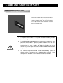
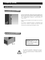
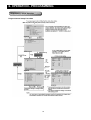
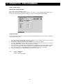
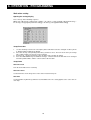
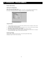
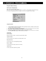
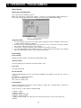
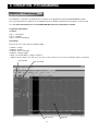
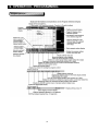
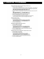
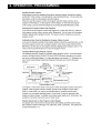
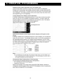
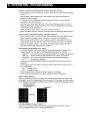
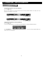
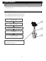
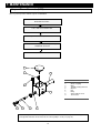
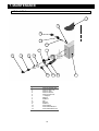
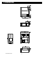
INSTRUCTION MANUAL
PLANT GROWTH CHAMBER (SGC170)
SGC170
CONTENTS
Section
1
2
3
3
4
5
6
7
8
9
10
11
Heading
HEALTH AND SAFETY
Foreseen Use of Chamber
UNPACKING AND CHECKING CONTENTS
Additional Accessory List
NAME AND FUNCTION OF PARTS
BEFORE USE
Safety and Pre-Installation Checks
INSTALLATION
Lifting Instructions
Positioning the Chamber
Electrical Power Supply Connection
Water Connection
OPERATION
Principles of Operation
Re-Operational Checks (Before turning ON
Switch)
Start Up
Shutdown
Programming
Data Aqcuisition
Communication Function
MAINTENANCE
Preventative Maintenance
Calibration of Temperature / Humidity sensor
Purified Water Filter
Vapour Phase Generator
Torbeck Tank
Replacing the Fluorescent Tube
Electrical Wiring Schematic
Refrigeration Wiring Schematic
TROUBLESHOOTING
SPECIFICATION
Dimensions
SPARE PARTS LIST
DISPOSAL/DECOMMISSIONING
Page
2
3
4
4
5
15
16
17
17
18
19
20
21
22
23
42
43
45
46
46
47
48
49
50
51
52
53
55
56
57
1. HEALTH AND SAFETY
Weiss Gallenkamp is required under the Health and Safety at Work, etc. Act. 1974 and other U.K. regulations as
designers, manufacturers, suppliers and importers of articles for use at work to ensure that, as far as reasonably
practicable, the product that we design, produce, supply or import are safe and without risk to health and safety,
when properly used.
We are also required to provide information on the safety and handling precautions to be observed when installing,
operating, maintaining and servicing our products. Such advice is contained in this manual.
We should also like to point out, however, that you as users have an important responsibility in the provision and
maintenance of safe working practices and conditions. Accordingly we draw the following matters to your attention:
1.
This apparatus should only be used as intended (see page 3), and within its design parameters by
suitably qualified and trained personnel who have read and understood the relevant sections of this
manual.
2.
This manual should be readily available at all times.
3.
In addition to that which is written in the manual, normal common sense safety precautions must be
taken at all times to avoid the possibility of accidents. Particular care is required when working with
apparatus at high temperatures or pressures.
4.
Installation, maintenance, servicing and connection to electrical supplies, should only be carried out by
suitably trained personnel. The Weiss Gallenkamp service department can provide these facilities if
required.
5.
If you are in any doubt whatsoever regarding the correct use of this apparatus, or if you require any
technical data or assistance, please contact Weiss Gallenkamp Technical Support.
Weiss Gallenkamp Limited
Units 37/38,
The Technology Centre,
Epinal Way
Loughborough,
Leicestershire, LE11 3GE
United Kingdom
Tel:
Fax:
E-mail:
+44 (0) 1509 631595 Sales
+44 (0) 1509 631590 Service
+44 (0) 1509 211133
[email protected]
[email protected]
Website: www.weiss-gallenkamp.com
NOTE: CAUTION MUST BE ADHERED TO
2
1. HEALTH AND SAFETY
Foreseen Use of Chamber
The SGC170 chamber has been specif ically designed f or tissue culture and the growing of plants. The chamber shall
be operating within the specif ication (see page 53). The chamber is not designed f or any other purpose.
3
2. UNPACKING AND CHECKING CONTENTS
1.
Caref ully remove all exterior packing materials and check f or any damage that may have occurred during
transit. DO NOT discard packing material until the chamber is fully operational. Report any damage
immediately to your supplier.
NOTE:
If the Shock Detection Indication shows red:
Do not reject the unit.
Notify the shipping company representative before
signing for the unit. When signing for the unit, note
any comments on the acceptance document.
Demand a copy of the acceptance document. If this
is not possible, notify the shipping company in
writing as soon as possible after taking delivery.
Notify the company who supplied the unit to you.
Caref ully unpack and inspect the unit for damage.
Report any damage found immediately to the
shipping company and the supplier.
Do not discard packing material.
2.
Remov e additional accessories, check the contents with the table below, and put them in a safe place.
3.
Check the interior of the chamber and remove any packing materials f rom the shelv es.
4.
Ensure the lamp is securely f itted; the two pins on each end of the f luorescent tube (FL) must line up with the
entry holes in the holders.
5.
Report any interior damage immediately to y our local supplier.
6.
The chamber is now ready for pre-installation check and installation (see page 15).
Additional Accessories List
Following accessories are included:
No
1
2
3
4
5
6
7
8
9
10
Part Name
Instruction Manual
DAQSTANDARD Software CDROM
CX2000 User manual CDROM
CX2000 Operation Guide
100Mb Zip Disk
630mA Antisurge Fuse
Wire Mesh Shelves
Wire Mesh Support Rods
Main Door Key
Instrument Chamber Door Key
4
Description
Quantity
UM-SGC170
1
1
1
1
1
1
2
4
1
1
E13033
K06607
K06608
K04346
3. NAME AND FUNCTION OF PARTS
LHS VIEW
FRONT VIEW
RHS VIEW
REAR VIEW
5
3. NAME AND FUNCTION OF PARTS
1. Air Inlet for Lamp Box
9. Instrument Panel Door
Air inlet For cooling of the lamps and ballasts
2. Access Port
Situated on the left hand side of the chamber. See
page 11
Remov e/Open cov er to gain access to the condensing
unit/electrical components f or servicing.
10. Purified Water Inlet
See page 13
3. Air Exchange
11. Waste water drain
4. Control Panel
12. Lamp Box Fans
5. Inspection Door
13. Refrigeration Air Outlet Grille
6. Lamp Box
14. Air Vent
7. Main Chamber Doors
15. Mains Electrical Cable Inlet
8. Refrigeration Air Inlet Grille
16. Lamp box Access Panel
See page 7
See page 13
See page 8
See page 12
Pull door open to view samples inside chamber
See page 15 and 17
Remov e cover to gain access to the lamp ballasts f or
serv icing
6
3. NAME AND FUNCTION OF PARTS
Air Exchange
An adjustable air v ent is provided on the f ront of the
chamber, the air v ent is opened by slide the hand to
the right hand side.
Up to 6 air changes per hour can be achieved with
the air vent opened to its maximum.
The silicone bung of the air vent should be remov ed
at the rear of the chamber.
REAR OF CHAMBER.
7
3. NAME AND FUNCTION OF PARTS
Control Panel Instrumentation
1
2
3
4
5
Programmable Controller / Recorder - See Separate
manual f or Operation and Programming
Mains Button
Reset Button
Mute Button
Mains Isolator
8
3. NAME AND FUNCTION OF PARTS
CX2000 Controller
Item Number
1
2
3
4
5
Description
LCD Screen
Identif ication Labels
Keys
Operation Cover
Key Operation Cover
LED Screen
Various screens appear in the LCD, such as the control group display and set up displays
Identification Label
Used to identify each channel, write the appropriate label as needed
Keys
Includes the directional arrow keys as well as the DISP/ENTER key. In operation mode, these keys are used to switch
between the operation displays. In the set up screens where f unctions are configured, the keys are used to select
parameters and to confirm new settings
Operation Cover
The external storage medium - zip disk is situated behind the operation cover. To open the cover press down on the
operation cover knob positioned at the top of the cover and then pull the cov er f orward. To remove the zip disk press the
small eject button to the right of the zip disk. Note the disk can only be remove when there is power to the controller
Ensure that the operation cov er is closed at all times except when handling the zip disk
Key Operation Cover
This cov er is opened to access to all of the other keys. The operation cover is opened by pulling the key operation cover
knob at the centre left corner of the cov er f orward.
9
3. NAME AND FUNCTION OF PARTS
Key Operation
1.
2.
3.
4.
5.
6.
7.
8.
Start Key – Starts the data acquisition to the internal memory, and displays the wav eform on the trend screen
Stop Key – Stops the data acquisition to the internal memory. Also stops the updating of the wav ef orm on the trend
screen.
Esc Key – Used when cancelling an operation. Also used when returning from the setting mode to operation mode
Menu Key – Used when switching from the operation mode to the setting mode. Also used when returning f rom
setting mode to the operation mode
User Key – Used to execute the assigned action
Func Key – If the key is pressed in the operation mode, a soft key menu is displayed at the bottom of the screen
enabling the execution of various f unctions. The key is also used when switching f rom setting mode to the operation
mode.
Soft Key – When a soft key is displayed at the bottom section of the display in operation, setting, or basic setting
mod, these soft keys are used to change the operation and set up inf ormation
Character/Number Keys – Used when entering characters or numbers.
10
3. NAME AND FUNCTION OF PARTS
Access Port
The access port is situated on the left-hand side of the chamber, the access
port has two plugs fitted, and one inside and one outside, and both plugs need
to be fitted to maintain the insulation of the chamber.
The plugs can be split or holes bored to enable wires or pipes to pass through
the port. Care must be taken to prev ent condensation f orming inside the
access port
11
3. NAME AND FUNCTION OF PARTS
Lighting System
Tungsten
Light
Cooling
Fans
Air Flow
Fluorescent Tubes
12
3. NAME AND FUNCTION OF PARTS
Purified Water Supply
If an AquaRec re-circulation pure water system is
prov ided, please refer to the AquaRec instructions
f or connection to this unit.
Connect a supply of purif ied water (see
specif ication page 15) to the inlet pipe situated on
the right hand side of the instrument
compartment. Maximum allowable head is
1500mm (5ft) above the inlet pipe.
Waster Water Drain
Connect a pipe to the cabinet outlet to
giv e a CONTINUOUS FALL to an OPEN
DRAIN. Drainage restriction may cause
airlocks and consequently f looding the
chamber.
13
3. NAME AND FUNCTION OF PARTS
Combined temperature/humidity probe
The chamber is fitted with an electronic combined
temperature/direct reading humidity probe, used f or
chamber condition control. The sensor is positioned
on the right hand side on the inside of the chamber
behind a removable plate
CAUTION:
1. It is important that the probe is not subjected to saturating humidity conditions
(i.e. condensing).
2.
It is probable that the probe, following a low temperature test, will form a dew
point if the chamber door is opened to ambient conditions. This will cause
condensation to form on the probe. To prevent this, reset the chamber
temperature to the same as ambient but with a low humidity and run the
chamber. Only after the probe has attained ambient conditions should the door
be opened.
3.
The combined temperature/humidity control and monitoring probes are
delicate, precision instruments. Only suitably qualified personnel should
attempt routine calibration checks in order to avoid damage to probes.
14
4. BEFORE USE
Safety and Pre-Installation Checks
To ensure the chamber operates correctly please check the following items bef ore using the chamber:
(1) Electrical Supply
Check that the electrical supply av ailable conforms to the information on the power rating plate (f ound on the side of
the chamber above the mains electricity supply cable) and is of sufficient power to run the product.
Check that the power supply is of the correct phase configuration – either single phase or phase to phase as
stated on the chamber rating plate, AC (alternating current) of the stated f requency with neutral nominally at
earth potential.
The supply voltage is within the stated range.
The current rating is within the capacity of the supply inlet.
The socket or outlet circuit is suitably f used.
(2) Facility checks
Check that the purified water supply for the chamber is of sufficient volumetric capacity
Check that a wastewater open drain or condense tray is av ailable and is of sufficient capacity
Check that the Purified water pressure is between 0.1-1.0 Bar (2-14 psi)
-1
Check that the Purified water has the correct conductivity between 5 - 20µS cm .
NOTE:
If the water pressure is higher than 1.0 bar a pressure reducing valve must be fitted in the supply line.
If required Weiss Gallenkamp Limited can supply a pressure reducing valve.
CAUTION: Ultra Pure Water will destroy the heater element and
can cause irreparable damage to the plant growth chamber.
(3) Ambient temperature
Ambient temperature operating range: + 12ºC to +25ºC
Check that the room where the chamber is to be installed is adequately ventilated, and ambient conditions do not
exceed the specification in terms of temperature and humidity.
(4) Noise emissions
•
The sound pressure level emitted by the chamber does not exceed 70dB(A)
(5) Areas for use
•
This chamber is not intended to be used in potentially explosive areas
15
5. INSTALLATION
Lifting Instructions.
500kg
The chamber should be lifted using a suitable
fork lift truck at the positions show. Care should
be taken w hen lifting the chamber not to damage
the drain pipe that is positioned on the underside
of the chamber.
16
5. INSTALLATION
Positioning the Chamber
450
900
450
INSTRUMENT
COMPARTMENT
Position the chamber in a v entilated area, on a
lev el stable surface with the following minimum
distances f rom continuous obstructions.
720
(1) Installation Checks
•
If the chamber is sited onto a bench please ensure that the bench is capable of supporting the chamber
weight and maximum chamber load combined. (See specif ication f or weights page 53):
Ensure that the chamber is lev elled to +/- 2mm.
•
•
Ensure the chamber is within easy reach of the power supply isolator.
•
Ensure open door will not cause an access hazard.
Electrical Power Supply Connection
The chamber should be installed by a competent person to BS 7671:2000, or y our local wiring regulations.
WARNING: This product must be earthed.
Chambers of higher current requirements are designed to be hard wired to a suitable power outlet by a
qualif ied electrician.
Consult a qualified electrician if in doubt or the supply has any of the f ollowing:
no earth
a colour code different f rom the above
rev ersible plugs
- supply and return leads that are both abov e earth potential
-
Machine is connected to a branch circuit that does not have a primary ty pe of ov ercurrent protection
(Since this machine utilises a supplementary ty pe of ov ercurrent protection.
415V 50Hz
Earth
Live L1
Live L2
Live L3
Neutral
Green/Yellow
Black
Black
Black
Blue (2)
17
5. INSTALLATION
Water Connection
Purified water supply connection
Connect the purif ied water supply to inlet connector situated on the
right side or at the rear of the chamber. Maximum allowable head is
1500mm (4ft 9ins above the inlet pressure). The purified water should
-1
hav e a conductiv ity range of 5-20µS cm , a pressure range of 0.11.0bar (2-14Psi)
Ideally any reserv oir should hav e its own support to one side of the
chamber.
If the chamber is supplied with an AquaRec, re-circulating pure water
sy stem, fill the reserv oir as instructed and connect the water
connections to the chamber water inlet and drain as shown.
Waste water drain connection
CAUTION: connect a pipe to give a
CONTINUOUS FALL to the drain.
Drainage restriction can cause an
airlock and consequent flooding of
the treatment chamber.
The outlet for the wastewater is situated at the rear of the
chamber. The connection size is 12.7mm OD. It is important
that the connection to the drain has a continuous fall to an
open drain
18
6. PRINCIPLES OF OPERATION
The chamber is split into three different sections, a treatment chamber, growing chamber and the light box
Air is conditioned in the treatment chamber and is constantly recirclated around the growing chamber. The system
is designed to give an airflow through the growing chamber with a high tolerance of temperature and humidity,
which will allow the user to repeat tests under the same growing conditions. The air velocity through the growing
chamber is fast enough to prevent micro climates but slow enough to prevent disturbing the specimen
The growing chamber is separated from the light box via a glass panel, fluorescent lamps are housed inside the
lamp box to simulate daylight, incandescent lamps are fitted to supplement the red/far red end of the lighting
spectrum.
Temperature
Accurate, repeatable temperature control is achieved by balancing continuous heat extraction with modulated heat
control by an electronic PID controller.
Heating
An Inconel sheathed heating elements sited in the treatment chamber. The element operates at black heat for long
life and excessive surface temperatures
Cooling
The purpose of providing cooling with the treatment chamber is for the following:
To provide a continuous heat extraction to balance the heating load
To introduce a cold surface on which to control the relative humidity of the chamber
Lighting
The light box houses the fluorescent tubes and incandescent lamps used to simulate daylight. The timing and the
intensity of the photoperiods are controlled via the programmer situated on the front of the chamber.
The incandescent lamps can be manually switched or automatically programmed to turn ON of OFF
The fluorescent lamps can be manually switched or automatically programmed to turn ON or OFF and the intensity
can be dimmed from 10% to 100% in steps of 1%.
The cooling fans inside the lamp box are switched on automatically when the lights are switched on. The inside
walls of the chamber are coated white to minimise light loss and to maximise diffusion.
19
6. OPERATION
Pre-Operational Checks (Before turning ON)
The chamber door keys are available to designated users to restrict control and sample access to authorised
personnel
The sample load will not release f lammable, noxious or otherwise hazardous v apours
Av oid using any materials in the chamber that may corrode in the humid atmosphere e.g. mild steel baskets, and
also av oid using Chlorine, Iodine or aggressiv e cleaning agent.
It is recommended that a chamber log book is kept which details both use, serv ice and calibration history of the
chamber
Users are familiar with the operation of the chamber, including, setting parameters, suitable samples, load
distribution, saf ety aspects, alarms and shut-down procedure as detailed in this manual
The chamber has been regularly maintained and calibration checked by suitably qualif ied engineers. It is
recommended that the chamber is serviced annually by Weiss Gallenkamp or their approv ed dealers or serv ice
agents
Standard operating procedures (SOP’s) have been prepared and made av ailable to the operators
Copies of this manual are available to the operator of the chamber
20
6. OPERATION
Start Up
1.
Switch on the mains power at the mains power connector
2.
Switch on the red/y ellow mains power isolator
3.
Press the Green Mains power switch on the main control panel
4.
Power is now av ailable to the controller
For Steady state control
At the ov erview screen on the controller, use the cursor keys to move to temperature, humidity or the lighting channels
1.
2.
3.
4.
5.
At the desired channel Press soft key [#2] SP and use the cursor keys to enter the required setpoint
Press ENTER
Ensure mode (soft key [#1]) is AUTO
Press soft key [#4] RUN/STP and set to RUN
Repeat for each channel
Ensure that the Fridge switch is set to ON
21
6. OPERATION
To switch on the Fridge, Fluorescent lights or tungsten lights move the cursor to the required switch
Press soft key [#1] Mode and set to Manual
Press soft key [#2] Out and set to 1 (0 is OFF 1 is ON)
Press the START button and the chamber will start to run and control at the required conditions
For Programm able control
See page 24 to set up a program and page 32 to run a program
Shutdow n
When the control is required to be terminated, press the MAINS POWER button. The push button will no longer be
illuminated
Turn the red/y ellow MAINS ISOLATOR to the OFF position. The chamber temperature will slowly drift to ambient
conditions.
Emergency Shutdown
Turn the red/y ellow MAINS ISOLATOR to the OFF position and switch off the main power supply to the chamber
22
6. OPERATION
Automatic Defrost
The chamber is fitted with an automatic def rost system, which is controlled by the CX2000 controller. The def rost control
switch can be seen on the overv iew screen along with the ev aporator coil temperature. The def rost switch should always
be left in the auto position so defrost period can determined on demand by the controller.
The purpose of the def rost system is to allow ice on the evaporator to melt. Both the f requency and the length of the
def rost period is automatically controlled.
The rate of build up of ice and hence the need f or def rosting is determined by the automatic def rost system, by switching
the ref rigeration unit off, this will occur prov iding the ev aporator coil has been below +2ºC f or ov er an hour. Once the
ev aporator coil temperature rises abov e +2ºC the refrigeration system will switch back on. The system will not def rost
again until the evaporator coil has been below 2ºC for another hour.
23
6. OPERATION - PROGRAMMING
Programming – Via the Controller
Program Control Setup Procedure
24
6. OPERATION - PROGRAMMING
Pattern Initial Setting
Opening the Settings Display
Press the keys in the f ollowing sequence:
MENU key (switch to the setting mode (control)) > #7 soft key (select [program-control parameters]) >
#1 soft key (select [program parameter setting]) > #1soft key (select [pattern initial setting])
Setup Procedure
Use the arrow keys to mov e the cursor (blue) to the item box you wish to change. A soft key is displayed
at the bottom of the screen
1.
2.
3.
4.
5.
6.
Press the soft key corresponding to the v alue y ou wish to select. The box for the item y ou changed
turns yellow, and the cursor moves to the next item
Repeat steps 1 and 2 to change the value of all the terms you wish to change
Press the DISP/ENTER key to conf irm the changes. The box for the items that hav e been changed
turn f rom yellow to white, and the cursor returns to the first item
Press the ESC key to return to the [program parameter setting] menu. To continue with the program
setting, press the [#1] to [#6] soft keys to display each setting display without carrying out step 6
Press the [End] soft key – A window appears f or confirmation to save the new settings.
Select [Yes] and press the DISP/ENTER key and save the settings.
Note:
Loop 1 – Temperature
Loop 2 – Humidity
Loop 3 – Fluorescent Lights
25
6. OPERATION - PROGRAMMING
Wait action setting
Opening the setting display
Press the keys in the f ollowing sequence:
MENU key (switch to the setting mode (control)) > #7 soft key (select [program-control parameters]) >
#1 soft key (select [program parameter setting]) > #1soft key (select [pattern initial setting])
Setup Procedure
1.
2.
3.
4.
Use the arrow keys to mov e the cursor (blue) to the item that needs to be changed. A soft key menu
is displayed at the bottom of the display.
Press the soft key corresponding to the v alue y ou wish to select. The box for the item y ou change
turns yellow, and the cursor moves to the next item
Repeat steps 1 and 2 to change the value of all the terms you wish to change
Press the DISP/ENTER key to conf irm the changes. The box for the items that hav e been changed
turn f rom yellow to white, and the cursor returns to the first item.
Setup Items
Wait zone off/on
Turn off/on the wait zone f or each loop
Wait zone values
Set the wait zones in the range of 0 to 100% of the measurement span
Wait Time
Set the wait time in [hh:mm:ss] f ormat f or each av ailable zone. The setting applies to the same zone in
each loop.
26
6. OPERATION - PROGRAMMING
Pattern Start setting
Opening the Setting Display
Press the keys in the f ollowing sequence:
MENU key (switch to the setting mode (control)) > #7 soft key (select [program-control parameters]) >
#1 soft key (select [program parameter setting]) > #1soft key (select [pattern initial setting])
Setup Procedure
1.
2.
3.
4.
Use the arrow keys to mov e the cursor (blue) to the item that needs to be changed. A soft key menu
is displayed at the bottom of the display.
Press the soft key corresponding to the v alue y ou wish to select. The box for the item y ou change
turns yellow, and the cursor moves to the next item
Repeat steps 1 and 2 to change the value of all the terms you wish to change
Press the DISP/ENTER key to conf irm the changes. The box for the items that hav e been changed
turn f rom yellow to white, and the cursor returns to the first item.
Pattern Start Setting
Pattern Number – Displays the pattern number selected in the pattern initial settings
Start target setpoint – Set the SP, for each loop
27
6. OPERATION - PROGRAMMING
Program Pattern Setting
Opening the Setting Display
Press the keys in the f ollowing sequence:
MENU key (switch to the setting mode (control)) > #7 soft key (select [program-control parameters]) >
#1 soft key (select [program parameter setting]) > #1soft key (select [pattern initial setting])
Setup Procedure
1.
2.
3.
4.
Use the arrow keys to mov e the cursor (blue) to the item that needs to be changed. A soft key menu
is displayed at the bottom of the display.
Press the soft key corresponding to the v alue y ou wish to select. The box for the item y ou change
turns yellow, and the cursor moves to the next item
Repeat steps 1 and 2 to change the value of all the terms you wish to change
Press the DISP/ENTER key to conf irm the changes. The box for the items that hav e been changed
turn f rom yellow to white, and the cursor returns to the first item.
Setup Items
Pattern Number
Displays the pattern number selected in the pattern initial settings
Segment number
Select the number of the segment to be changed f rom 1 to 99
Ramp/Soak select
Select the ty pe to be specified ([Ramp] or [Soak])
Target Setpoint
Set the f inal SP of the ramp segment f or each loop
Segment time
Set the segment time in [hh:mm:ss] format.
28
6. OPERATION - PROGRAMMING
Event Setting
Opening the Setting Display
Press the keys in the f ollowing sequence:
MENU key (switch to the setting mode (control)) > #7 soft key (select [program-control parameters]) >
#1 soft key (select [program parameter setting]) > #1soft key (select [pattern initial setting])
Setup Procedure
1.
2.
3.
4.
Use the arrow keys to mov e the cursor (blue) to the item that needs to be changed. A soft key menu
is displayed at the bottom of the display.
Press the soft key corresponding to the v alue y ou wish to select. The box for the item y ou change
turns yellow, and the cursor moves to the next item
Repeat steps 1 and 2 to change the value of all the terms you wish to change
Press the DISP/ENTER key to conf irm the changes. The box for the items that hav e been changed
turn f rom yellow to white, and the cursor returns to the first item.
Ev ent Setting
Pattern Number
Displays the pattern number selected in the pattern initial settings
Segment number
Select the number of the segment to be changed f rom 1 to 99
Event Kind
Select the [TimeEvent]
On1/On2/On3/Off
Set the On/Offsetting type for each event f rom the following. Select [Off] for vents that are not to be
assigned.
On1 (On/Off) Use On time and Off time
On2 (On/**) Use On time only
On3 (**/Off) Use off time only
On-time/Off time
Set the on time/Off time of the time ev ent in hh:mm:ss format. The selectable range is 00:00:00 to
99:59:59. Set Off time ≥ On time
Timed ev ents are used to switch on and off the lights
1) SW001 – Fridge
2) SW002 – Defrost **
3) SW003 - Fluorescent Lights
4) SW004 – Tungsten Lights
** Alway s leav e the def rost set to Off, and set to auto on the overv iew screen to ensure defrost on
demand.
29
6. OPERATION - PROGRAMMING
Repeat Action
Opening the Setting Display
Press the keys in the f ollowing sequence:
MENU key (switch to the setting mode (control)) > #7 soft key (select [program-control parameters]) >
#1 soft key (select [program parameter setting]) > #1soft key (select [pattern initial setting])
Setup Procedure
1.
2.
3.
4.
Use the arrow keys to mov e the cursor (blue) to the item that needs to be changed. A soft key menu
is displayed at the bottom of the display.
Press the soft key corresponding to the v alue y ou wish to select. The box for the item y ou change
turns yellow, and the cursor moves to the next item
Repeat steps 1 and 2 to change the value of all the terms you wish to change
Press the DISP/ENTER key to conf irm the changes. The box for the items that hav e been changed
turn f rom yellow to white, and the cursor returns to the first item.
Setup Items
Pattern Number
Displays the pattern number selected in the pattern initial settings
Repeat Action
Select the repeat function from [Off], [On] and [Repeat]
Repeat Frequency
Set the number of repetitions when the repeat f unction is turned ON in the range of [1] to [999]
Repeat start segment/Repeat end segment
Set the repeat start segment number and the repeat end segment number when the repeat f unction is
turned ON or when the repeating in the range of 1 to 99.
For more information please refer to the CX2000 User’s Manual
30
6. OPERATION - PROGRAMMING
Programming – Via DAQSTANDARD
If the CX2000 is connected to a network then the controller can be programmed using the DAQSTANDARD software.
Once the program has been written it can be downloaded to the controller. A maximum of four programs can be stored at
once. For more information please see the DAQSTAND ARD manual included with the chamber
Programming Information
Set points
Loop 1 – Temperature
Loop 2 – Humidity
Loop 3 – Fluorescent Lighting
Timed Event
Timed ev ents are used to switch on and off the lights
1)
2)
3)
4)
SW001
SW002
SW003
SW004
– Fridge*
– Defrost **
- Fluorescent Lights
– Tungsten Lights
* Alway s ensure that SW001 – Fridge is turned on
** Always leave the defrost set to Off, and set to auto on the ov erview screen to ensure automatic defrost on demand
Set Point Tab
Time Ev ent Tab
Time Ev ents
31
Segments
6. OPERATION - PROGRAMMING
Program Operation
32
6. OPERATION - PROGRAMMING
33
6. OPERATION - PROGRAMMING
34
6. OPERATION - PROGRAMMING
35
6. OPERATION - PROGRAMMING
36
6. OPERATION - PROGRAMMING
37
6. OPERATION - PROGRAMMING
38
6. OPERATION - PROGRAMMING
39
6. OPERATION - PROGRAMMING
40
6. OPERATION - PROGRAMMING
41
6. OPERATION – DATA ACQUISTION
Data Acquisition – Internal Memory
Starting Data Acquisition to the Internal Memory.
Press the START button.
When the data acquisition to the internal memory starts, the memory operation indicator icon changes from stop
indication to run indication as shown below.
Stopping Data Acquisition to the Internal Memory.
Press the STOP button
Use the left and right arrow keys to select [Memory] of [Mem+Math] in the conf irmation window that appears
Press DISP/ENTER key. When the data acquisition to the internal memory stops, the memory operation indicator icon
changes from run to stop indication.
42
6. OPERATION – COMMUNICATION FUNCTION
By using the Ethernet interf ace that is f itted to the controller data can be transf erred on to a server in two methods:
1. FTP Server
The controller can be accessed from a PC to retriev e f iles from the external storage dev ice
2. FTP Client – Automatic File Transfer
The display data f ile, event data f ile, and the report f ile can be automatically transferred to a remote FTP server, The
result of the transfer is conf irmed on the FTP log screen.
Up to two files destinations can be specif ied (primary and secondary ). If the primary serv er is down, the file is transferred
to the secondary f ile.
43
6. OPERATION – COMMUNICATION FUNCTION
Web Server
The controller screen can be display ed on the browser applications of Microsoft Internet Explorer. Two screens are
av ailable. The screen can be updated at a constant period.
1. Monitor Page
Screen f or dedicated for monitoring. The f ollowing information can be display ed.
•
•
•
Alarm Summary
Measured/computed data of all channels
Logs (Message summary, error log, FTP log, email log, Web operation log, setting change log)
2. Operator Page
In addition to the contents on the monitor page the controller screen can be switched to different views.
Email Transmission
The controller can transmit emails to specified destinations at the f ollowing times:
•
•
•
•
When an alarm is active/released
During recovery f rom a power f ailure
When memory end is detected
When an error related to the external storage medium and FTP client occurs
For more information on the controller communication functions and setup please refer to the communication
manual included with the chamber
44
7. MAINTENANCE
Preventive Maintenance.
All maintenance and servicing should only be carried out by suitably trained and qualified personnel.
The cabinet has been designed and built for a long life and required minimal attention and maintenance. Howev er,
regular attention to the few points f ew points will ensure a long and trouble free operation.
If the cabinet does f ail, the expertise of our service engineers is readily av ailable f or either diagnostic adv ice or non-site
attendance. Service and calibration contracts are av ailable from our serv ice department.
Weekly or post test if longer.
Cleaning. Do not use cleaning agents that contain ‘hypochlorite’ as these may attack stainless steel.
Check Drain Accumulation of contaminants f rom the test samples can block the treatment chamber drain. To inspect the
drain, remove the two screws holding the treatment chamber cover and remove the panel. The drain in the base should
be f ree from contaminants that could block it.
Monthly.
Check Thermostat.
Adjust the thermostat through the prev ailing cabinet temperature. Check for the correct function. In the ev ent of the
thermostat being f aulty Rectify the f ault at once. The thermostat should switch the chamber OFF
Purified Water Inlet.
The f ilter inside the clear plastic bowl is located inside the instrument compartment, after the water inlet nozzle, this can
be inspected by looking through the viewing hole. The clear plastic bowl and filter can be unscrewed and removed for
cleaning.
To clean the f ilter (see page 43), disconnect the water supply, open the instrument compartment door, unscrew the filter
bowl and remov e the f ilter. Clean or replace the f ilter and clean the bowl. Reassemble in reverse order. Care must be
exercised so that water is not splashed onto other areas in the instrument compartment.
Float Valve.
The f loat valv e maintains the level of purified water f or the v apour phase generator. The float v alve, in the chamber
should be checked for correct operation. Open the instrument door, remov e the loose lid from the constant level device
Refrigeration Unit Cleaning.
Switch off the mains power supply, remove the ventilation panels, gently brush/blow/vacuum dust etc from the f ins and
tubes of the condenser coils
Annually.
Checking of the calibration, and if necessary of the combined temperature/humidity probe is recommended on a y early
basis. It is recommended that Weiss Gallenkamp service engineers perf orm the calibration as errors may be caused by
other f actors, such as humidity and temperature controllers.
45
7. MAINTENANCE
Calibration of Electronic temperature/Humidity Probes
Combined electronic temperature and relative humidity probes carry a valid calibration certif icate. Calibration should
be checked after one y ear.
Purified Water Filter
This is located below the purif ied water inlet, and can be
inspected through the v iewing hole in the rear of the chamber.
The clear plastic bowl and filter can be remov ed f or cleaning.
Switch Off chamber and ISOLATE from the
ELECTRICAL SUPPLY.
1
Switch OFF
Disconnect water supply.
Open instrument compartment door / panel
2
Unscrew the bowl (Item 3) and remove the filter (Item 2).
Clean or replace.
Reassemble in reverse order, ensuring that the filter is
ref itted the correct way up.
NOTE:
Please check the filter once a month, if it looks dirty, or
contaminated clean or replace.
46
3
7. MAINTENANCE
Vapour Phase Generator (VPG)
Once a year inspect the VPG f or signs of contamination
Switch Off chamber and ISOLATE from the
ELECTRICAL SUPPLY.
Leave VPG to Cool down if HOT
Open Instrument Compartment Door
Remove VPG lid (Item 7) and inspect for any
contaminants and clean
Reassemble in reverse order
7
6
8
9
1
2
3
4
ITEM
1
2
3
4
5
6
7
8
9
DESCRIPTION
VPG Tank
Wade Coupling
Oliv e
1500W Heating Element
Washer
Nut
Bung
38mm Silicone Port
Thermostat
5
NOTE: Ultra pure water will destroy the heater element and can cause irrepairable damage to the
plant growth chamber. Ensure water of the correct quality is used (see page 15)
47
7. MAINTENANCE
Torbeck Tank
2
9
11
7
10
4
8
7
6
3
5
14
Item Number
1
2
3
4
5
6
7
8
9
10
11
12
13
14
13
12
Description
Torbeck Welded Tank
Torbeck Tank Lid
Torbeck Valv e
Torbeck Washer
Torbeck Back Nut
½” Adapter
Adapter
90ºBend
Nut
Washer
90ºBend
Float Switch
Float Switch Washer
Float Switch Back Nut
48
1
7. MAINTENANCE
Replacing the Fluorescent Tube
FLUORESCENT LAMPS
TUNGSTEN LAMPS
Switch Off chamber and ISOLATE from the
Switch Off chamber and ISOLATE from the
ELECTRICAL SUPPLY.
ELECTRICAL SUPPLY.
Lift Light box cover
Lift Light box cover
Remove the old fluorescent tube by rotating 90º
Rotating the end cover plate 90º to expose the end
cap and remove the tube
Align the pins on the replacement tube with the slots
Insert new tube by pushing the end cap into the spring
in the tube holder and rotate 90º
loaded holder and rotate the end cover plate
Shut Light box lid
Shut Light box lid
49
)) 0
'"
50
.
Gallenkamp
E nvi ro nment al Si mula ti on Li mi t ed
! "# $
& # '
(" + #)
,
" % & " ' (
' " ) )" '
* &
# " '( # -('
'
Tol er an ces to : I SO 2 768- m U .O . S.
0- 120 mm ±0. 3 120- 40 0mm ±0 .5
400 -1 000mm ±0. 8 1 000- 20 00mm ± 1.2
&
.
# # /
D O N OT S C ALE
7. MAINTENANCE
+0
Electrical Wiring Schematic
",
7. MAINTENANCE
Refrigeration Schematic
51
8. TROUBLESHOOTING
All Maintenance And Servicing Should Be Carried Out By Suitably Trained And
Qualified Personnel.
CONTROL PANEL
FAULT SYMPTOM
Power Switch
illuminated
on
POSSIBLE CAUSE
but
not
Power switch will not switch on
Power switch in but controllers
not illuminated
INSTRUMENT COMPARTMENT
Electricity power failure
Indicator lamp failed
Heater circuit f ault
Vapour phase generator fault
Refrigeration fault
Safety thermostat faulty
Safety thermostat set too low
MCB trips and will not reset
Fan motor failure
Air Heater failure
VPG Heater failure
Lighting Circuit failure
Controller electrical failure
Light Cooling Fan failure
Cabinet is tripped by safety
thermostat
(or over temperature drift)
Set point incorrect
TEMPERATURE CONTROL
Under temperature drift
Chamber stable but below or
above temperature set point
HUMIDITY CONTROL
If the humidity control is too high
or low:
52
Thermostat set incorrectly or faulty
If output on the controller is 0% then
controller fault or a ref rigeration f ault
Set point incorrect
If output on the controller is 100%
then controller fault or heater fault
Chamber
operated
outside
env ironmental specif ication
See over and under temperature drift
Set points are incorrect
Chamber is being operated outside
env ironmental conditions
Treatment
chamber flooded –
wastewater drain blocked
Low water switch in the torbeck tank
broken/damaged
Thermostat on the Vapour Phase
Generator tank tripped – press to
reset
Venting incorrect
Vapour phase generator heating
element failed
9. SPECIFICATION
Plant Growth Chamber- Specifications
MODEL
PHYSICAL
SGC170
Floor Mounted
External
Dimensions
WxDxH (mm)
Working Chamber
Dims. WxDxH
Working Volume
Outer Case
Inner Chamber
Shelves
Maximum Shelf
Loading
Maximum Chamber
Loading
Supports
Weight
Drain
Vent
ACCESS
Air Exchange
Cable Port
Doors
ELECTRICAL
Supply Voltage
Maximum Current
WATER
Purified Water
Requirement
Drain
Heat Dissipation
CONTROLS
Controllers
Sensors
Humidification
Heating
Airflow System
Lighting
2285 x 1000 x 2150
1400x 800 x 1480
1700 litre
Zinc Coated Mild Steel with stoved acrylic textured finish
Type SUS 304 Stainless steel with a reflective coating
2 off plastic coated steel half depth shelves
10kg
50kg
4 Castors – 2 front castors lockable
500 Kg
22mm diameter - provided for drainage of evaporator condensate
Rear silicone vent to allow for air volume expansion and contraction during temperature
changes- and prevent vapour build-up
I off Air exchange vent on the front of the chamber
1 off 66mm diameter silicone in left-hand side wall
Full width / height insulated double doors.
Viewing window in LHS door with light shield
Instrument, chamber and electrical compartment doors are lockable.
415V 50Hz 3 Phase 50Hz
17 Amps
For humidification system. Conductivity 5 to 20µS cm -1
Supply pressure range 2-14p.s.i. (0.1-1bar). Water filter provided
22mm diameter - provided for drainage of evaporator condensate to open drainage point
7.32kW
* Heat Dissipation is calculated at 415 V
Microprocessor controlled digital temperature and humidity controllers
High specification solid-state capacitance humidity probes with PRT temperature
sensing.
Vapour phase humidity generator with low water level protection for prevention of water
borne contamination.
‘Inconel’ electrical resistive heating operating at ‘black heat’.
Vertical airflow direction upwards @ 0.2m/s.
20 off 58W TLD 84 Fluorescent tubes plus 8 incandescent lamps air-cooled in a light
box. Variable intensity from 10% to 100% of maximum.
53
Microprocessor based integrated system management for reliability and high energy
System
efficiency and rapid condition recovery following sample loading
Management
PERFORMANCE
Ambient Operating +12°C to +25°C
Range
+7°C to +40°C (lights on)
Temperature Only
0°C to +40°C (lights off)
Control Range
±0.3°
C @40ºC
Temperature
Fluctuation (with
time)
±1°C
Temperature
Uniformity (spatial)
25% to 88% @ +40ºC
Temperature &
42% to 95% @ +20ºC
Humidity Control
50% to 95% @ +10ºC
Range
±3% relative humidity on average
Humidity
Uniformity
0.2m/sec (turbulent) (average within empty working chamber)
Air Velocity
SAMPLE LOAD PROTECTION
Safety Thermostats Independent high safety thermostat capable of shutting down chamber.
OPTIONAL ACCESSORIES
Self contained recirculating purified water system - with filtration, deionisation and UV
Water Supply
sterilisation built-in.
Compiles with the essential health and safety requirements of
Compliance
Machinery Directive 98/37/EC and its amendments
Electromagnetic Compatibility Directive 89/336/EEC and its amendments
Low Voltage Directive 73/23/EEC and its amendments
54
9. DIMENSIONS
SGC170 Dimensions
55
10. SPARE PARTS LIST
PART NUMBER
K06517
K06541
E70118
33100.221
K04648
E20036
E20505
E22550
K02191
E13033
E04041
K02302
36090.035
37070.008
E47027
E47028
K04346
K06607
K06608
K06719
K06720
72100.472
DESCRIPTION
Main Door Seal
Inspection Door Seal
2500W Chamber Heating Element
1500W VPG Heating Element
Air Circulation Fan Motor
Fluorescent Tube
Tungsten Lighting
Lighting Ballast
Lamp Box Cooling Fan
Fuse Anti-Surge 630mA
Temperature and Humidity Sensor
Water Filter
Float Switch For Torbeck Tank
Thermostat For VPG Tank
Thermostat For Lamp Box
Thermostat For Chamber
Latch Key For Main Door
Replacement Mesh Shelf
Mesh Shelf Support Rods
38mm Port Plug
66mm Port Plug
VPG Bung
56
11. Disposal/Decommissioning
The remov al of components after their use should be environmentally f riendly. The chamber should be delivered to a
company that specialises in the complete removal.
The table below lists all details of remov al and repeated use of individual parts of the chamber
Product
Steel construction frames, Impellers,
pipelines
Material
Metals
Removal
Separation of materials
Insulated case and doors
Metals, PU f oam
Cables casings and plugs
Electronic Assemblies
Rubber, PVC, silicone, PTFE and
similar artif icial materials
Artif icial materials, metals, electrolyse
Fluorescent Tubes
Glass, metals (inc. Mercury )
Melting procedure for repeated use
(recycling)
Separation of materials
Special incineration procedure
Separation of materials
Recycling
To special waste dumps in compliance
with all local regulations
To special waste dumps in compliance
with all local regulations
Products with coatings should be delivered for processing to enable their repeated use, depending on the type of
coating, or be taken to special waster dumps in compliance with all local regulations
57
WEISS GALLENKAMP LIMITED
Unit 37/38
The Technology Centre
Epinal Way
Loughborough
Leicestershire
LE11 3GE
United Kingdom
Tel:
+44 (0)1509 631595 Sales
+44 (0)1509 631590 Service
Fax:
+44 (0)1509 211133
E-mail: [email protected]
UM-SGC170 Issue A
First Issued for S170PFXF10001
[email protected]
Website www.weiss-gallenkamp.com
58