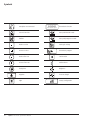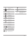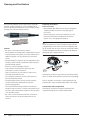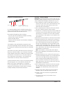
1
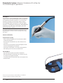
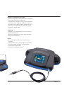
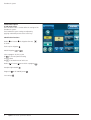
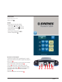
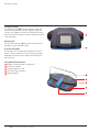
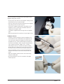
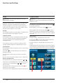
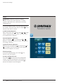
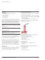
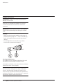
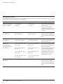
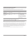
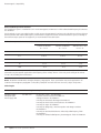
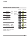
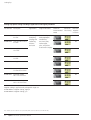
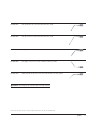
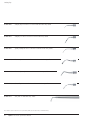
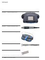
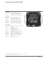
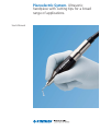
Piezoelectric System. Ultrasonic
handpiece with cutting tips for a broad
range of applications.
User’s Manual
Table of Contents
Introduction
Functions and Settings
Synthes
Intended use
2
Features and benefits
2
Technical description
4
Warnings
8
Installation
10
Startup
12
Irrigation function
12
Light function
12
Piezoelectric System function
13
Toolbox
14
Safety
15
Shutting down the device
15
Cutting tips
16
Maintenance
Electromagnetic Compatibility
Additional Information
Product Information
Irrigation line maintenance
17
Device maintenance
17
Handpiece maintenance
18
Fuse replacement
19
Operating faults
20
Electromagnetic emissions
21
Electromagnetic immunity
22
Separation distances and cable lengths
24
Disposal and recycling
25
Manufacturer’s liability
25
Regulations
25
Symbols
26
Cleaning and sterilization
28
Cutting tips
33
Instruments
38
Set list
39
Synthes
Piezoelectric System. Ultrasonic handpiece with cutting tips
for a broad range of applications.
Intended use
The Piezoelectric System distributed by Synthes is an ultrasonic
surgical system consisting of handpieces and associated tips
for cutting bone and bone substitutes. It can be used for
osteotomy, osteoplasty, decorticating, drilling, shaping,
and smoothing of bones and teeth in a variety of surgical
procedures, including general orthopaedic, otolaryngological,
maxillofacial, oral, hand, foot, neurosurgical, spine, and
plastic/reconstructive surgery.
To maximize the benefits of this device and ensure it has a
long working life, read this manual carefully before using
the system.
Features and benefits
Cruise Control™ System
– No loss of power regardless of the environment and/or
treatment performed
– Active only on mineralized tissue, with minimal risk to
soft tissue
– Minimum pressure required, resulting in higher precision
and less hand fatigue for the clinician
– Four power setting modes: 3 for bone cutting based on
bone density and 1 for soft tissue detachment
LED handpiece
– Up to 60 watts of power for efficient osteotomies
– No heat generation and vibration free, minimizes the risk
of necrosis and surgeon discomfort
– Six powerful LEDs for enhanced vision at the operative site
– Attached cable
The list of accessories referred to in this manual is non-exhaustive.
Consult your Synthes Consultant for further details.
2
Synthes Piezoelectric System User’s Manual
Progressive, multifunction foot pedal
– Real-time adjustment of the ultrasonic power according to
the anatomical constraints encountered
– The power of the ultrasonics can be precisely adapted for
areas where nerves, arteries or membranes are present
– Total control of the console through the foot pedal, which
allows hands-free operation in the sterile field, without
touching the console screen
Cutting tips
– Irrigation is transmitted through the tip to prevent heat
generation and necrosis
– Narrow kerf for highly precise bone surgery procedures
– Broad range of applications
Console
– User-friendly touch-sensitive LCD screen for ease of
operation
– Cable connectors for up to two handpieces, eliminating
the need to change cutting tips during procedures
– Two peristaltic pump housings
– Two brackets for irrigation solution
Synthes
3
Piezoelectric System
Technical Description
a) LCD touch screen
The LCD touch screen is used to define the settings of the
Piezoelectric System.
The Piezoelectric System settings are adjusted by
applying reasonable pressure to the screen keys.
Identification functions
Reduce
or increase
in ml/min
the irrigation flow rate
Flush or prime irrigation
ON/OFF irrigation
or
Select a program: D1, D2, D3, D4
D1
is the most powerful setting
for dense bone
D4
is for detachment of soft tissue
Reduce
or increase
power within a program
Handpiece light ON/OFF
Progressive
or full ON/OFF power
Save settings
4
Synthes Piezoelectric System User’s Manual
Startup screen
Identification of key areas:
Toolbox mode
Toolbox
Identification of information display
– Audio volume
symbol and value
– Screen brightness symbol
and value
– Light off/time-out symbol
and value
– Software version
– Reset factory configuration
– Validate configuration
b) Control unit back panel
The power receptacle with its grounding pin is used to
connect the console to the power supply using a plug-in
power cord 1 .
The foot pedal connector is used to connect the console
to the multifunction control foot pedal 2 .
The fan 3 , protected by a metal grille, keeps the
Piezoelectric System at its optimum performance level.
The irrigation pole holders 4 hold the irrigation poles.
The power switch is used to switch the console
ON or OFF 5 .
Potentiated equipment connector plug 6 .
4
2
3
6
1
5
4
Synthes
5
Piezoelectric System
c) Irrigation pumps
The irrigation pumps 6 are located on either side of the
console, and accommodate Synthes irrigation tubing with
cassettes. The irrigation cassettes are installed by lifting the
pump covers and inserting the cassettes horizontally into the
cassette housings.
6
d) Front panel
The two cable connectors 7 accept the connector of the
Piezoelectric System handpiece cable.
7
e) Control foot pedal
The functions on the control foot pedal allow the user to
work in a sterile environment. Once the settings have been
adjusted on the console, the user does not need to touch
the LCD screen.
Foot pedal button definition
1 Handpiece control (ON/OFF or progressive)
2 Flush/prime irrigation
3 Change program (D1– D4)
4 Select left or right handpiece
5 Irrigation ON/OFF
5
4
3
2
1
6
Synthes Piezoelectric System User’s Manual
f) Technical characteristics
Manufacturer: SATELEC
Distributor: Synthes, Inc. USA
Device name: Piezoelectric System
Electrical power supply
Voltage: 100 VAC to 230 VAC
Frequency: 50 Hz/60 Hz
Rated power: 150 VA at 230 VAC
Piezoelectric System function
Operation
Intermittent service: 10 min. ON/5 min. OFF
Output characteristics
No-load voltage: 250 volts
(nominal value without handpiece)
Min. ultrasonic frequency: 28 kHz
Irrigation flow rate: 10 to 120 ml/min. (nominal value)
Adjustment in 10 ml/min. steps (nominal value)
Flush flow rate: 120 ml/min. (nominal value)
Overall dimensions
Control unit
Width: 472.9 mm
Height: 149.5 mm
Height with bracket: 471.1 mm
Depth: 339.9 mm
Weight: 5 kg without accessories
Handpiece cable
2.9 meters
Temperatures
Operation: +10°C to +30°C
Storage: -20°C to +70°C
Humidity
Operation: 30% to 75%
Storage: 10% to 100% including condensation
Atmospheric pressure
Between 500 hPa and 1060 hPa
Protection
Electrical equipment class: Class 1
Electrical safety class: BF
Safety devices
Safety shut off if internal malfunction
2 fuses (power receptacle):
5 mm x 20 mm/2 AT for 100 VAC to 230 VAC
1 internal fuse not accessible to the user
Reference F1: 5 mm x 20 mm – 10 AT/250 VAC
Synthes
7
Warnings
Caution: United States Federal Law restricts the use of
this device solely to qualified, trained and competent health
practitioners or personnel under their supervision.
Device users
Attention:
– The Synthes Piezoelectric System must not be used if the
patient and/or the operator has a cardiac stimulator
(pacemaker) or any other active implant (e.g. a cochlear
implant).
– Use of the Synthes Piezoelectric System is restricted solely
to qualified, trained and competent health care
practitioners in the normal context of their work.
– If you have received this device in error, please contact
your Synthes Consultant.
Interactions
– The device complies with applicable electromagnetic
compatibility standards. However, the user should ensure
that any potential electromagnetic interference does not
cause an additional risk (presence of radiofrequency
emitters, electronic devices, etc.).
– The device is not designed to withstand shocks delivered
by an electric defibrillator.
– Do not attempt to connect to the Piezoelectric System
connectors any accessories other than those supplied by
Synthes.
Caution: The tips are specifically designed for the Synthes
Piezoelectric System. The system is not compatible with other
systems tips.
8
Synthes Piezoelectric System User’s Manual
To reduce the risk of accidents, the precautions stipulated
below must be taken.
Electrical connection
To avoid risk of electric shock, this device must be connected
to an electrical power supply with a protective ground.
– The electric supply to which the device is connected must
comply with the standards in force in your country.
– If loss of electrical power during use is likely to generate
an unacceptable risk, the device must be connected to a
suitable power source (e.g. UPS).
Using the device
– Do not use the device if it appears to be damaged or
faulty.
– Turn the device OFF before unplugging the power cord.
– To unplug the power cord, grip the cord plug and hold the
wall socket.
– Never use any irrigation solution containers other than
those intended for suspension from the supplied brackets.
– The device must only be used with bottles or bags of
physiological saline or sterile water.
– The capacity of the irrigation solution containers used
must not exceed one liter per bracket.
– When the device is not to be used for a long period of
time, unplug the console from the electric supply.
– Do not exert excessive force on the screen.
– Do not move the console during use.
Overheating, burns
To avoid any risk of burns or overheating, irrigation must
always be switched ON and active when the handpiece is
in use.
The user shall regularly control the level of irrigation to
ensure its coolant action to the tip. A lack of irrigation
presents a hazard to the patient.
Environment
– Do not cover the console or obstruct the ventilation vents.
– Do not immerse the device in liquid, and do not use it
outdoors.
– Do not tilt the console at an angle greater than 5°.
– Do not place the console near a heat source.
– Ensure that the cables and power cord are not in a
traffic path.
– The device must be stored in an appropriate and safe
place.
– Do not store or operate system near flammable or
combustible gas or liquid storage areas.
– Do not expose the console to water vapor, or splashes.
– Condensation inside an electrical device may be
dangerous.
– If the console must be moved from a cool place to a hot
place, allow it to warm up to the new room temperature
before use.
– The device is not designed to work near ionizing radiation.
– Do not insert metal objects into the device (risk of electric
shock, short-circuit or emission of hazardous substances).
Maintenance
– Before and after each procedure, ensure that all
accessories are cleaned, disinfected and sterilized.
– Synthes recommends that the Torque Wrench be replaced
or checked for the proper torque at least once every
2 years.
Accessories
– The device and accessories have been designed and
developed together to ensure maximum safety and
performance.
– Use of accessories from other manufacturers is a potential
hazard to the user, the patient and the device.
Repairs
Do not attempt to repair or to modify the device without
authorization by Synthes. When the device is modified or
repaired, specific checks and verifications must be
performed to ensure that the device can be used safely.
In the case of a fault, contact your Synthes Consultant for
repair. Your system is warranted for defects for one year
from the date of purchase. Use of unauthorized repairers
could damage the system and void the warranty. If in doubt,
contact your Synthes Consultant.
Synthes
9
Installation
Unpacking the device
Upon receipt of the device, check for any damage caused in
transit.
Contact your Synthes Consultant if necessary.
Recommendations
The electrical connection of the Piezoelectric System must
comply with the applicable standards in your country.
Warning: To avoid any risk of electric shock, this device
must be connected to an electrical power supply with a
protective ground.
Installation
Important: Do not place the Piezoelectric System close
to or on top of another device. Do not place the power cord
and the foot pedal cable in a wire cover or in a cable guard.
Do not operate the handpiece unless the irrigation is
switched to the ON position. Do not disconnect the handpiece cables when the device is switched ON and the foot
pedal is pressed. Do not insert or remove cutting tips when
the handpiece is ON. The handpiece, wrench and graphic
case must be cleaned, disinfected and sterilized before each
use. Do not use the system with parts other than those
supplied by Synthes. Check the integrity of the device and
its accessories before and after each use in order to detect
any problems.
10
Synthes Piezoelectric System User’s Manual
– Position the console on a fixed horizontal surface, or one
with a slope of no more than 5°.
– Check that the power switch is in the OFF position.
– Connect the power cord to the receptacle on the back of
the console. If necessary, connect the potential
equalization connector to the console.
– Connect the power cord to a grounded power outlet.
– Connect the foot pedal cable to the foot pedal connector
on the back of the console.
– Position the foot pedal so that it is easily accessible for use.
– Insert the irrigation poles into the bracket holders.
– Connect the handpiece cable to the connector on the front
of the console. The default setting is for the right connector.
– Ensure that the console is close enough to the work area
to be used without pulling on the cables or power cord.
– Place the handpiece on the sterile field.
The pump housings are designed to accommodate Synthes
irrigation tubing with cassettes.
– Lift the pump cover and insert the irrigation tubing cassette
horizontally into the cassette housings.
– Insert the sterile spike into the connection on the irrigation
bag, taking care to not touch the spike.
– Connect the irrigation tubing to the cannulation on the
handpiece. Use the sterile clips provided to attach the
tubing to the handpiece cable.
– Suspend the irrigation bottles or bags from the irrigation
poles.
– Adjust the position of the console to suit your angle of view.
Handpiece function
– Thread the selected cutting tip onto the handpiece. Use
the Flat Wrench or the Torque Wrench to tighten the tip.
Turn the wrench clockwise to tighten. Be careful not to
overtighten the tip, which could damage the threads on
the tip or the handpiece. When using the Torque Wrench,
turn it clockwise until one audible “click” is heard,
indicating that the tip is secured with optimum torque.
Do not continue to tighten the tip once the click is heard.
To remove the tip, turn the wrench counter-clockwise.
– Prime the irrigation circuit by pressing the flush/prime
button on the console screen or the multifunction foot
pedal.
– When the irrigation solution reaches the end of the tip,
release the foot pedal.
– Use the Piezoelectric System in accordance with good
medical practices.
Synthes
11
Functions and Settings
Startup
c) Irrigation ON/OFF
Important: After turning the console off, wait four
seconds before restarting it.
Important: To avoid any risk of burns or overheating,
irrigation must always be switched ON and active when the
handpiece is in use.
By default, when the device is switched on, the right-hand
handpiece is selected if two handpieces are connected.
If only one handpiece is connected, the device selects the
correct side. If no handpiece is connected, the device selects
the right side in Piezoelectric System mode.
The irrigation is switched ON or OFF by pressing button
or the foot pedal button.
When irrigation is selected, the symbol
is shown.
Settings
The settings are saved when each program is configured and
are retrieved whenever that program is selected.
When irrigation is not selected, the symbol
is shown.
Irrigation must always be switched ON when the handpiece
is in use. Damage to the tip or necrosis may result if irrigation
is not used.
Irrigation function
The Piezoelectric System is not designed to administer drugs.
It must be used only with bottles or bags of physiological
saline or sterile water with an individual capacity not
exceeding one liter.
The Piezoelectric System must only be used with Synthes
supplied irrigation tubing that is designed for the system.
a) Flush/prime
The flush/prime function is located on the LCD screen and on
the foot pedal.
Press button
or the foot pedal button to switch on the
flush/prime function.
Light function
The light function is displayed on the LCD screen.
Pressing button
switches the light function available for
the Piezoelectric system functions ON or OFF.
The light function has a default light-off time-out of nine
seconds.
The light function switches OFF when the time-out has elapsed.
If necessary, you can change the light time-out by changing the
settings in the Toolbox section of the Console screen option.
The flush/prime function stays on as long as the button is
pressed.
The flush can be switched on while the device is being used.
b) Flow rate adjustment
The irrigation flow rate is adjusted using buttons
or
.
Each time the corresponding button is pressed, the flow rate
is adjusted. Press and hold buttons
or
to scroll the
flow rate values.
The adjusted value is displayed on the LCD screen 1 and
stored in the current program.
The flow rate can be adjusted while the device is being used.
1
12
Synthes Piezoelectric System User’s Manual
2
Piezoelectric System function
Important: The Piezoelectric System function settings
can be customized by the user. The Piezoelectric System
function settings can be adjusted whether or not a handpiece is connected to the console.
The Fine Tuning function 2 gives the possibility to adjust
the level of power energy within each mode from 1 to 5.
Select the left or right Piezoelectric System function by
pressing Synthes button or the foot pedal button.
Power Level
Program
Mode
Main functions
Very powerful
D1
Osteotomy, osteoplasty
Important: In progressive mode, for programs D1 to D3,
the delivered power ranges between power level 1 of program
D3 and the configuration defined by the user (program and
power level). In progressive mode, the power delivered by
program D4 ranges only between levels 1 and 5, according
to the value defined by the user.
Powerful
D2
Osteotomy, osteoplasty
Select handpiece light ON/OFF, by pressing button
Medium
D3
Osteotomy, osteoplasty
Low
D4
Soft tissue detachment
The program giving the highest power is D1.
Level of Fine Tuning
Power value
2
3
82%
86%
90%
Frequency Modulation
Power value
1
2
64%
68%
Frequency Modulation
4
5
72%
74%
78%
D3
2
3
4
5
44%
48%
52%
56%
60%
60 Hz
Program Mode
Power value
3
1
Frequency Modulation
Level of Fine Tuning
95% 100%
60 Hz
Program Mode
Power value
5
D2
Frequency Modulation
Level of Fine Tuning
4
60 Hz
Program Mode
Level of Fine Tuning
Repeat this sequence if necessary in order to adjust all the
programs.
D1
1
.
The saving of the various settings is confirmed by an audible
signal and a visual signal (button flashing).
Programs correspond to the following level of powers:
Program Mode
Confirm the new settings by pressing button
.
D4
1
2
3
4
5
41%
46%
51%
56%
60%
30 Hz
Synthes
13
Functions and Settings
Toolbox
Important: Piezoelectric System has a Toolbox
function used to make various adjustments, including
brightness, light off/time-out, audio volume and factory
configuration reset.
To access the Toolbox function, switch the device OFF, wait
four seconds, switch device ON, then press button
on the
welcome screen within 2 seconds.
a) Audio volume adjustment
Adjust audio volume value
using buttons
or
. Audio
volume is adjustable from 0% to 100%. The relative value
of the audio volume is displayed.
b) Screen brightness adjustment
Adjust the brightness
value using buttons
or
.
Brightness is adjustable from 30% to 100%. The brightness
level setting is displayed.
c) Light off/time-out adjustment
Adjust the time-out length value
by using buttons
or
. The length of the time-out function can be adjusted
from nine (9) to eighteen (18) seconds.
d) Storing settings
To store the modified settings, press button
welcome screen will reappear.
. The
e) Factory configuration reset
Press button
to restore the factory configuration
settings. The factory configuration for the Piezoelectric
System functions becomes effective when button
is
pressed. The welcome screen will reappear.
14
Synthes Piezoelectric System User’s Manual
f) Software version
The version of the software is displayed at the bottom of the
Toolbox screen.
The Piezoelectric System is configured in the factory with the
following settings:
Shutting down the device
Upon completion of the medical procedure:
– Remove the bottles or bags of irrigation from the brackets.
– Remove the irrigation line spike from the bottle or bag.
– Immerse the irrigation line spike in a vessel containing
distilled or sterile water.
Piezoelectric mode
Program
mode
Power
level
Irrigation
Very
powerful
D1
3
60 ml/min.
Powerful
D2
3
60 ml/min.
Medium
D3
3
60 ml/min.
Low
D4
3
60 ml/min.
Main
functions
Osteotomy,
osteoplasty
Soft tissue
detachment
Important:
– Rinse to remove saline solution from the handpiece by
running the prime/flush function until the vessel and the
irrigation line are completely empty.
– Switch the device OFF (O).
– Remove the irrigation tubing clips.
– Disconnect the irrigation tubing from the handpiece and
dispose in a safety container for soiled medical items.
– Disconnect the handpiece from the console.
– Disconnect the ultrasonic single-use tips and dispose in a
safety container for soiled, sharp, medical instruments.
Safety
The console is equipped to detect malfunctions of the device.
If an internal operation error occurs, the transmission fault
symbol
is displayed in the error zone and the device
beeps four times. To cancel this default, simply switch OFF
the device from the ON/OFF button. Wait a few seconds and
switch ON again to restart the device.
When the handpiece is disconnected, the handpiece missing
icon
is displayed in the error zone and the device beeps
four times.
Synthes
15
Functions and Settings
Cutting Tips
The cutting tips are divided in four categories:
– Cutting saw tips
– Cutting diamond tips
– Cutting scalpel tips
– Decorticating tips
These cutting tips can be used for osteotomy, osteoplasty,
decorticating, drilling, shaping, and smoothing of bones and
teeth in a variety of surgical procedures, including general
orthopaedic, otolaryngological, maxillofacial, oral, hand,
foot, neurosurgical, spine, and plastic/reconstructive surgery.
Caution: The tips are specifically designed for the Synthes
Piezoelectric System. The system is not compatible with other
manufacturer’s tips.
Cutting saw and diamond tips
The intended uses of the tips are osteotomy and osteoplasty.
Use a “brush-stroke” movement:
– Place the tip perpendicular to the surface to be treated 1
– Move the tip with a slow back and forth movement, in line
with to the cut 2
– Apply only very slight pressure — never use force
NEVER USE THE TIP AS A LEVER: use only the appropriate
elevator to lift the bone graft.
1
90°
Principles of utilization
2
Important: An efficient use of these ultrasonic tips
requires very slight pressure to be effective.
The power of the Piezoelectric System applied to each cutting
tip should be set on the console screen according to the
recommended mode, fine tuning and irrigation level. Refer
to page 33 for recommended power settings.
To avoid any risk of burns or overheating, irrigation must
always be switched ON and active when the handpiece is in
use. The user shall regularly control the level of irrigation to
ensure its coolant action to the tip. A lack of irrigation
represents a hazard to the patient. The irrigation level is
given as a minimum and must be increased when necessary.
Duration of use
Cutting tips are provided sterile, for single use only, and can
be used continuously, as long as the maximum power and
minimum irrigation settings are strictly followed.
16
Synthes Piezoelectric System User’s Manual
Cutting scalpel tips
The intended uses of this tip category are osteotomy,
osteoplasty and bone harvesting.
Use a repeated, short pulling movement
– Apply slight pressure
– Never use force
– Never use the tip as a lever
Decorticating tips
The intended use of this tip category is soft tissue
decortication.
During its use, it is essential to keep contact with the
soft tissue and the bone.
– Apply slight pressure
– Never use force
– Never use the tip as a lever
Maintenance
Maintenance/sterilization
Important: The device must be switched OFF during
reprocessing procedures.
Do not use disinfection agents containing flammable
substances.
Do not sterilize or reuse cutting tips or irrigation tubing. The
maintenance and/or sterilization instructions provided in this
guide must be applied before each use of the device.
Sterilized items must be allowed to dry and cool to room
temperature before use. Universal precautions for handling
contaminated/biohazardous material should be observed.
The console and foot pedal must always be cleaned after
each procedure, using a neutral pH cleaner.
Regular monitoring of the Piezoelectric System is necessary
in order to detect any problem.
Keep the console ventilation vents clean, to avoid abnormal
heating.
The handpiece and cable can be sterilized in an autoclave.
For Minimum Sterilization Requirements refer to page 32.
Caution: After multiple uses, and during successive
sterilizations, make sure before use that the handpiece-cable
assembly is not damaged.
Caution: The tips are specifically designed for the Synthes
Piezoelectric System. The system is not compatible with other
systems tips.
Irrigation line maintenance
Sterile irrigation tubing
Caution: The irrigation tubing supplied by Synthes is
for single-use only, and must always be discarded after use.
Do not resterilize the single-use irrigation tubing. Do not
attempt to modify the irrigation tubing. The reuse of the
irrigation tubing is a potential hazard to the surgeon, patient
and the device.
Device maintenance
Important: Never use an abrasive cleaning agent on the
console or the foot pedal.
Do not use sprays or liquids to clean and disinfect the
console.
Do not immerse the console or foot pedal.
Do not sterilize the console or the foot pedal.
Synthes
17
Maintenance
Handpiece maintenance
Important: Handpiece must be disassembled prior to
cleaning and sterilization.
After each use, the handpiece irrigation circuit must be
rinsed with distilled or sterile water for a minimum of
20 seconds.
Important: Before medical procedures, test the LED to
verify the correct positioning of the LED ring on the handpiece.
Assembly
– Connect the LED ring to the handpiece, making sure it is
positioned correctly (align the “+” marks on the LED ring
and on the handpiece body near the LED ring electrical
contacts).
– Insert the light diffuser over the LED ring as shown.
– Screw the nose cone onto the handpiece.
Cleaning and disinfection
The handpiece must be cleaned and disinfected after each
procedure by manual cleaning or automatic washer.
For handpiece sterilization, refer to the minimum sterilization
requirements for the system (page 32).
Note: Cutting tips are provided sterile for single-use only.
Do not reuse tips. Cutting tips must always be discarded
after use. Do not attempt to modify the cutting tip. The
reuse of the tip may lead to the decrease of its performance
and proper characteristics. The reuse of the tips is a potential
hazard to the surgeon, patient and the device.
18
Synthes Piezoelectric System User’s Manual
Important: Do not attempt to repair or modify the
device without authorization from Synthes. When the device
is modified or repaired, specific checks and verifications must
be performed to ensure that the device can be used safely.
Preventive and corrective maintenance
The Piezoelectric System does not need any preventive
maintenance other than monitoring of the accessories and
routine cleaning/disinfection.
Do not use an unauthorized repair center, which might make
your device dangerous for you and/or your patient.
Fuse replacement
The Piezoelectric System is protected by two fuses located
in the power receptacle.
To replace the fuses:
– Switch the device OFF (position O).
– Unplug the power cord from the electrical power supply.
– Unplug the power cord from the receptacle. Insert the tip
of a flat screwdriver into the notch above the fuse drawer
to release it.
– Replace the old fuses with new fuses of the same type and
rating.
– Push the fuse drawer back into its housing until it clicks to
indicate the correct position.
– Plug the power cord into the receptacle. Plug the power
cord into the electrical power supply.
Warning: In the case of a fault, contact your Synthes
Consultant for repair. Your system is warranted for defects
for one year from the date of purchase. Use of an unauthorized repair center could damage the system and will void
the warranty. If in doubt, contact your Synthes Consultant.
Monitoring
Regular monitoring of the device and its accessories is
necessary in order to detect any insulation fault or damage.
It is important to keep the control unit ventilation vents
clean, to avoid overheating.
Note: The device also has an internal fuse not accessible to
the user.
Contact your Synthes Consultant for service.
Synthes
19
Maintenance
Operating faults
Fault detected
Possible causes
Solutions
Device does not operate
(LCD screen off)
Power cord not plugged in properly.
Check the electric socket.
Contact your Synthes Consultant.
Power switch in position O (OFF).
Place the power switch in position I (ON).
No power voltage.
Contact your Synthes Consultant.
Power receptacle fuse(s) blown.
Replace the power receptacle fuses.
Internal fuse blown.
Contact your Synthes Consultant.
Device does not operate
(LCD screen on)
Transmission fault.
Switch the device OFF then ON again.
Contact your Synthes Consultant.
No spray
Irrigation solution bag or bottle empty.
Replace the bag or bottle of irrigation solution.
Irrigation off.
Press the irrigation ON/OFF button.
Irrigation line clogged.
Change irrigation tubing.
Inadequate spray
Incorrect irrigation flow rate adjustment.
Adjust the irrigation flow rate.
Power fault
weak tip vibration
Tip worn or distorted.
Replace the tip.
Incorrect power adjustment.
Refer to page 33 for the necessary information.
Incorrect use: incorrect angle
of attack or inadequate pressure
on the cutting surface of bone.
Contact your Synthes Consultant.
Incorrect tip tightening.
Retighten the tip with the wrench.
Faulty connector contact.
Clean the connector contacts.
Handpiece cable wire cut.
Contact your Synthes Consultant.
Handpiece light ring absent.
Install the light ring.
Faulty light ring.
Replace the light ring.
Faulty light ring connector contacts.
Clean the light ring connector contacts.
Light ring oriented incorrectly.
Position the light ring according to the
positioning index.
Faulty handpiece and/or cable
connector contacts.
Clean the handpiece and/or cable connector contacts.
Other.
Contact your Synthes Consultant.
Broken tube in the irrigation
tubing cassette.
Replace the irrigation tubing.
No ultrasonic function
No light
Leak in the
irrigation pump
If the suggested solutions are unsuccessful, please contact your Synthes Consultant or the Synthes Service Department at 1 (800) 288-6698.
20
Synthes Piezoelectric System User’s Manual
Electromagnetic Compatibility
Important: The power cord, the ultrasonic handpiece
cables and the multifunction foot pedal cable must be kept
away from each other.
The Piezoelectric System requires special precautions
regarding electromagnetic compatibility. It must be installed
and prepared for use as described below.
Certain types of mobile telecommunication devices such as
mobile telephones can interfere with the Piezoelectric system.
The recommended separation distances, as specified in the
tables below, must be complied with.
The Piezoelectric System must not be used near or on top of
another device. If this cannot be avoided, its operation under
the conditions of use must be checked beforehand.
The use of accessories other than those specified or sold by
Synthes may damage the system and void the warranty.
Electromagnetic emissions
The Piezoelectric System is intended for use in the electromagnetic
environment specified in the table below. The user and/or
installer must ensure that the system is used accordingly.
Emission test
Compliance
Electromagnetic environment
RF emission — CISPR 11.
Group 1
Piezoelectric System uses RF energy for internal operation.
Therefore, its radiofrequency emissions are very low and are
not likely to cause any interference in nearby equipment.
RF emission — CISPR 11.
Class A
Harmonic current emission IEC 61000-3-2.
Class A
Piezoelectric System is suitable for use in all establishments,
other than domestic establishments and those directly
connected to the public low voltage power supply network
that supplies buildings used for domestic purposes.
Voltage fluctuation and flicker IEC 61000-3-3.
Complies
Synthes
21
Electromagnetic Compatibility
Electromagnetic immunity
The Piezoelectric System is intended for use in the electromagnetic environment specified in the table below. The user and/or
installer must ensure that the device is used accordingly.
Immunity test
Test level
Compliance level
Electromagnetic environment
Electrostatic discharge
(ESD) IEC 61000-4-2.
± 6 KV contact
± 8 KV air
± 6 KV contact
± 8 KV air
Floors must be wood, concrete,
cement or tiled.
If floors are covered with
synthetic material (carpet, etc.),
the relative humidity must be at
least 30%.
Electrical fast transients
IEC 61000-4-4.
± 2KV for
power supply lines
± 2KV for
power supply lines
Mains power quality should be
that of a typical commercial or
hospital environment (hospital,
clinic).
Surges
IEC 61000-4-5.
± 1KV differential mode
± 2KV common mode±
1KV differential mode
± 2KV common mode
Mains power quality should be
that of a typical commercial or
hospital environment.
Voltage dips,
short interruptions
and voltage variations
IEC 61000-4-11.
<5% UT (>95% dip in UT)
for 0.5 cycles.
<5% UT (>95% dip in UT)
for 0.5 cycles.
40% UT (60% dip in UT)
for 5 cycles
40% UT (60% dip in UT)
for 5 cycles
70% UT (30% dip in UT)
for 25 cycles
70% UT (30% dip in UT)
for 25 cycles
Mains power quality should be
that of a typical commercial or
hospital environment.
If the use of the system requires
continued operation during
power mains interruption, it is
recommended that the product
be powered from a separate
power supply (UPS, etc.).
<5% UT (>95% dip in UT)
for 250 cycles
<5% UT (>95% dip in UT)
for 250 cycles
3A/m
3A/m
Magnetic field at 50Hz
IEC61000-4-8
22
Synthes Piezoelectric System User’s Manual
The intensity of the magnetic
field should be equivalent to
that of a typical commercial or
hospital environment (hospital,
clinic)
Electromagnetic immunity/radiofrequency mobile equipment
The Piezoelectric System is intended for use in the electromagnetic environment specified in the table below. The user and/or
installer must ensure that the device is used accordingly.
Portable and mobile radiofrequency communications devices must not be used near the system (including its cables) at a
distance less than that recommended and calculated according to the frequency and power of the emitter.
Immunity test
Test level
Compliance level
Electromagnetic environment
Conducted disturbance,
radiofrequency fields.
IEC61000-4-6
3 V/m
150 KHz to 80 MHz
3 V/m
Recommended separation distance:
Radiated radiofrequency
electromagnetic field.
IEC61000-4-3
3 V/m
80 MHz to 2.5 GHz
3 V/m
d = 1.2 √P
d = 1.2 √P 80MHz to 800MHz.
d = 2.3 √P 800MHz to 2.5GHz.
Where P is the maximum power rating
of the emitter in watts (W) according to
the manufacturer's specifications and d
is the recommended minimum separation
distance in meters (m).
The electromagnetic field strengths of fixed radiofrequency emitters, as determined by an electromagnetic environment
measurement (a), must be less than the compliance level in each frequency range (b).
Interference may occur near equipment marked with the symbol
.
Notes: At 80 MHz and 800 MHz, the higher frequency range applies. These specifications may not be applicable in all
situations. Electromagnetic propagation is affected by absorption and reflection from structures, objects and persons.
(a): The electromagnetic field strengths of fixed radiofrequency emitters, such as base stations for mobile telephones (cellular/
cordless), mobile radios, amateur radio, AM/FM radio broadcasts and TV broadcasts cannot be determined exactly by theory.
To assess the electromagnetic environment due to fixed radiofrequency emitters, an electromagnetic environment
measurement must be made. If the measured radiofrequency field strength in the immediate environment where the product
is used exceeds the compliance level specified above, the performance of the product must be tested to verify whether it
conforms to the specification. If abnormal performance is observed, additional measures may be necessary, such as
reorienting or relocating the product.
(b): In the 150 kHz to 80 MHz frequency range, the electromagnetic field strengths must be less than 3 V/m.
Synthes
23
Electromagnetic Compatibility
Recommended separation distances
The Piezoelectric System is intended for use in an electromagnetic environment in which radiated radiofrequency disturbances
are controlled.
The Piezoelectric System user and/or installer can help prevent electromagnetic interference by maintaining a minimum distance
between portable and mobile radiofrequency communications equipment emitters and the Piezoelectric System, according to
the maximum output power of the equipment, as recommended in the table below.
Rated max. power of the emitter (W)
Separation distance in meters (m) according to emitter frequency
150 KHz to 80 MHz
80 MHz to 800 MHz
800 MHz to 2.5 GHz
d = 1.2 √P
d = 1.2 √P
d = 2.3 √P
0.01
0.12 m
0.12 m
0.23 m
0.1
0.38 m
0.38 m
0.73 m
1
1.2 m
1.2 m
2.3 m
10
3.8 m
3.8 m
7.3 m
100
12 m
12 m
23 m
For emitters rated at max. power not listed above, the recommended separation distance d in meters (m) can be
estimated using the equation applicable to the frequency of the emitter, where P is the max. power rating of the emitter
in watts (W) according the manufacturer.
Notes: At 80 MHz and 800 MHz, the higher frequency range applies. These specifications may not be applicable in all
situations. Electromagnetic propagation is affected by absorption and reflection from structures, objects and persons.
Cable lengths
Cables and accessories
Maximum length
Complies with:
Handpiece cables
Foot pedal cable
Power supply cord
Less than 3 m
RF emission, CISPR 1, Class B/Group 1
Harmonic current emission: IEC61000-3-2
Voltage fluctuation: IEC61000-3-3
Immunity to electrostatic discharge: IEC61000-4-2
Immunity to electrical fast transients/bursts: IEC61000-4-4
Immunity to surges: IEC61000-4-5
Immunity to voltage dips, short interruptions and voltage variations:
IEC61000-4-11
Immunity to conducted disturbances induced by radiofrequency fields:
IEC61000-4-6
Immunity to radiated radiofrequency electromagnetic fields: IEC61000-4-3
24
Synthes Piezoelectric System User’s Manual
Additional Information
Disposal and recycling
As electrical and electronic equipment, the device must be
disposed of according to a specialized procedure for
collection, pick-up and recycling or destruction (in particular
on the European market, with reference to Directive
n.2002/96/EC of 27/01/2003).
When your device reaches the end of its life, please contact
your Synthes Consultant for information on how to proceed.
Manufacturer’s liability
The manufacturer is not liable if:
– The manufacturer’s installation recommendations have not
been followed (supply voltage, electromagnetic
environment, etc.).
– Repairs or other work have been done on the device by
persons not authorized by the manufacturer.
– The device has been used connected to an electrical
system that does not comply with current regulations.
– The device has been used in ways other than those
specified in this manual.
– Accessories (tips, handpiece, irrigation lines, etc.) other
than those supplied by Synthes have been used.
– The sterile single use accessories have been reused.
– The instructions in this document have not been followed.
Note: The manufacturer reserves the right to modify the
device and/or the user’s manual without notice.
Regulations
This medical device is classified as Class II according to
US Regulation (21 CFR 888.4580).
This equipment is manufactured in compliance with the
current IEC60601-1, IEC60601-1-1 and IEC60601-1-4
standards.
This equipment is manufactured in compliance with the
UL60601-1 and CAN/CSA C22.2 No. 601.1 standards.
This equipment has been designed and manufactured
according to an ISO 13485 certified quality assurance
system.
Synthes
25
Symbols
Handpiece not connected
26
SYNTHES
Piezoelectric System
Piezoelectric function
Transmission fault
Foot pedal ON/OFF mode
Toolbox
Foot pedal progressive mode
Reduce a value
Storing of settings
Increase a value
Piezoelectric program
Reduce flow rate
Confirmation
Increase flow rate
Audio volume
Flush/prime
Brightness
Irrigation
Time-out length
Light
Factory configuration
Synthes Piezoelectric System User’s Manual
I
Refer to the accompanying
documentation
Potential equalization connector
Class BF
Single use, do not re-use
Class 1
CE marking
Rx ONLY
United States Federal law restricts
this device to sale by or on the order
of a physician or other licensed
health-care provider.
Do not dispose of
in household waste
Date of manufacture
Alternating current
Control foot pedal
0
Device power OFF
I
Device power ON
Handpiece ON
Degree of protection against
liquid of the Control foot pedal
MEDICAL EQUIPMENT
UL60601-1
CAN / CSA C22.2 No. 601.1
!
3ZG5
WITH RESPECT TO ELECTRICAL SHOCK,
FIRE AND MECHANICAL HAZARDS ONLY
IN ACCORDANCE WITH UL60601-1
AND CAN / CSA C22.2 No. 601.1
Synthes
27
Cleaning and Sterilization
These recommendations are for reprocessing, specifically
cleaning, Synthes Piezoelectric System reusable medical
devices, including the Piezoelectric System handpiece-cable
assembly, flat wrench and torque wrench.
Cautions
– Do not use steel wool or abrasive cleaners.
– Avoid solutions containing iodine or high chlorine content.
– Contaminated or used Synthes accessories should not be
loaded in a graphic case and cleaned in a mechanical
washer.
– Metallic handpiece nosepiece, LED ring, light diffuser and
handpiece-cable assembly cannulation require particular
attention during cleaning.
– All devices must be thoroughly cleaned.
– Synthes doesn’t recommend or support the flash
sterilization of Synthes instruments.
– Synthes instruments are critical devices and must be
terminally sterilized prior to use.
– The sterilization parameters are only valid for devices
that are adequately cleaned.
– The following parameters are only valid for properly
installed, maintained, calibrated and compliant
reprocessing equipment.
– The recommended cleaning method for Piezoelectric
handpiece and accessories is manual and mechanical. Do
not place Synthes Piezoelectric handpiece-cable assembly
in an ultrasonic cleaner.
– Use a soft, lint-free cloth moistened with a neutral pH
cleaner to wipe the console and foot pedal. Do not
immerse.
28
Synthes Piezoelectric System User’s Manual
Processing instructions
Point of use care
– Wipe blood and/or debris from the devices throughout
surgical procedure to prevent it from drying onto
the surface.
– After the operation, remove the single-use tip at the
front of the Piezoelectric handpiece assembly and
dispose of it in the appropriate container.
Important: In the operating room, rinse the irrigation
line of the Piezoelectric System handpiece-cable assembly
using distilled or sterile water. Operate the irrigation pump
for 20 seconds after each use to prevent the drying of debris
inside the handpiece. Disconnect and dispose of irrigation
tubing and clips in proper container.
Soiled devices should be separated from noncontaminated
devices to avoid contamination of personnel or surroundings.
Devices should be covered with a towel dampened with
purified water to prevent blood and/or debris from drying.
Containment and Transportation
Soiled devices should be transported separately from
noncontaminated devices to avoid contamination.
Preparation for decontamination
Nose cone
LED ring
Light diffuser
Piezoelectric
handpiece-cable assembly
It is recommended that devices should be reprocessed as
soon as possible following use. Synthes devices should be
reprocessed no more than two hours after use.
Disassemble the handpiece prior to cleaning
– The front part of the Piezoelectric handpiece assembly,
the nose cone, must be unscrewed.
– Remove the light diffuser.
– Disconnect the LED ring from the Piezoelectric handpiece,
pulling it gently.
The handpiece, cable and handpiece components (nose
cone, LED ring and light diffuser) and torque wrench should
be manually pre-cleaned prior to processing in an automated
washer.
Soak and/or rinse heavily soiled devices prior to cleaning, to
loosen any dried soil or debris. Use a neutral pH enzymatic
cleaner solution to soak devices. Follow the enzymatic cleaner
manufacturer's instructions for use, for correct exposure
time, temperature, water quality (i.e. pH, hardness) and
concentration. Use cool tap water to rinse devices.
Synthes Piezoelectric devices must be first cleaned separately
from their graphic cases. Lids should be removed from
graphic cases for the cleaning process, if applicable.
It is the responsibility of the end user to ensure that all
equipment used to reprocess Synthes devices is properly
installed, validated, maintained and calibrated.
Cleaning — manual method
Equipment: Soft-bristled brushes, lint-free swab, soft, lintfree cloth, syringes, pipettes or water jet, neutral enzymatic
cleaner and/or neutral detergent solution with a pH≤ 8.5.
1) Rinse soiled device under running cold tap water for a
minimum of two minutes. Use a soft-bristled brush and/
or lint-free swab, soft, lint-free cloth to assist in the
removal of gross soil and debris.
2) Use a syringe, pipette or water jet to flush the cannulation with a neutral enzymatic cleaner solution.
3) Soak device in a neutral pH enzymatic cleaner solution for
a minimum of ten minutes. Follow the enzymatic cleaner
manufacturer's instructions for use for correct exposure
time, temperature, water quality (i.e. pH, hardness) and
concentration.
4) Rinse device with cool water for a minimum of two minutes.
5) Manually clean device for a minimum of five minutes in
a freshly prepared neutral pH enzymatic cleaner solution.
Use a soft-bristled brush to remove soil and debris on
the nose cone, light diffuser, LED ring, handpiece-cable
assembly and the threaded fitting. Gently use a lint-free
swab to remove soil and debris on the inside of the nose
cone, and LED ring. Clean device under water to prevent
aerosolization of contaminants.
Note: fresh solution is a newly-made, clean solution.
6) Rinse device thoroughly with deionized or purified water
for two minutes.
7) Manually clean device for a minimum of two minutes in
a neutral pH detergent solution. Use a soft-bristled brush
for the nose cone, light diffuser, LED ring, handpiececable assembly and the threaded fitting. Gently use a
lint-free swab for the inside of the nose cone, optical
guide and LED ring. Clean device under water to prevent
aerosolization of contaminants.
8) Use a syringe, pipette, or water jet to flush the cannulation with deionized or purified water and rinse device
thoroughly with deionized or purified water for two
minutes.
9) Visually inspect device. Repeat the manual cleaning
procedure until no visible soil remains on devices.
10) Perform a final rinse on device using deionized or
purified water.
11) Dry device using a soft, lint-free cloth or clean
compressed air.
Synthes
29
Cleaning and Sterilization
Cleaning – mechanical method
Note: Ultrasonic cleaning may cause further damage to
devices that have prior surface damage.
Equipment: Soft-bristled brushes, lint-free swab and/or
soft, lint-free cloth, syringe, pipettes, and/or water jet,
ultrasonic cleaner, washer/disinfector, neutral enzymatic
cleaner and/or neutral detergent with a pH ≤ 8.5.
Note: Ultrasonic process – flat wrench, nose cone and
torque wrench only.
1) Disassemble device if applicable. (Refer to page 29 for
disassembly information.)
2) Rinse soiled device under running cold tap water for a
minimum of one minute. Remove gross soil using a
soft- bristled brush, a lint-free swab or soft, lint-free cloth.
3) Manually clean device for a minimum of two minutes in
a freshly prepared neutral pH enzymatic cleaner solution.
Follow the enzymatic cleaner manufacturer's instructions
for the correct dilution, temperature, water quality (i.e.
pH, hardness) and exposure time. Use a soft-bristled
brush and/or lint-free swab to remove soil and debris.
Clean device under water to prevent aerosolization of
contaminants.
Note: Fresh solution is a newly-made, clean solution.
4) Rinse device using cool to lukewarm running tap water
for a minimum of one minute. Use a syringe, pipette or
water jet to flush cannulation.
5) Prepare a fresh detergent solution using a neutral pH
enzymatic cleaner. Follow the enzymatic cleaner manufacturer’s instructions for the correct dilution, temperature,
water quality (i.e. pH, hardness) and exposure time.
Ultrasonic process — flat wrench, nose cone and
torque wrench only.
Note: Fresh solution is a newly-made, clean solution.
6) Clean only flat wrench, nose cone and torque wrench
ultrasonically for 15 minutes.
7) Rinse device in cool to lukewarm running tap water for a
minimum of two minutes. Use a syringe, pipette or water
jet to flush the cannulation.
8) Visually inspect device. Repeat Steps 2 – 7 until no visible
soil remains on device.
30
Synthes Piezoelectric System User’s Manual
Mechanical method – (after preclean)
Use the following cycle parameters:
Cycle
Time
(minutes)
Temperature/
Water
Type of Detergent
Pre-wash 2
Cold tap water
N/A
Wash I
2
Cool to warm
tap water
Neutral enzymatic
pH ≤ 8.5
Wash II
5
Warm tap water
(>40°C)
Detergent
pH ≤ 8.5
Rinse
2
Warm DI or
PURW (>40°C)
N/A
Dry
40
90°C
N/A
Thermal Disinfection
For automated cleaning, thermal disinfect at 93°C for a
minimum of 5 minutes.
Drying
If a dry cycle is not included in a mechanical washer or if
the device is not processed in a mechanical washer:
– Dry each device thoroughly inside and out to prevent
rusting and malfunction.
– Use a soft, lint free cloth to avoid damage to the surface.
– Pay special attention to threads or areas where fluid can
accumulate.
– Open and close devices so that all areas are reached.
– Dry hollow parts using the medical air jet with clean
compressed air.
Synthes
31
Cleaning and Sterilization
Sterilization
Inspection
Synthes nonsterile Piezoelectric system devices must be
terminally sterilized prior to use.
– Synthes instruments should be inspected after processing
(any method listed above).
– The recommendations provided above have been validated
by the medical device manufacturer as being capable of
preparing a non-sterile Synthes implant or reusable medical
device. It remains the responsibility of the processor
to ensure that the processing is actually performed, using
equipment, materials and personnel in the reprocessing
facility, and achieves the desired result. This requires validation and routine monitoring of the process. Likewise,
any deviation by the processor from the recommendations
provided should be properly evaluated for effectiveness
and potential adverse consequences.
– All users should be qualified personnel with documented
expertise, competency and training. Users should be
trained on hospital policies and procedures along with
current applicable guidelines and standards.
– Users should wear appropriate personal protective equipment
(PPE) when processing devices.
The following are the recommendations for the sterilization
of the components stored in the graphic case (handpiece
and cable, handpiece components (nose cone, light diffuser,
and LED ring) and flat wrench).
Cycle Type
Min Sterilization Min Sterilization Min
Exposure Time
Exposure
Dry Time
(minutes)
Temperature
Prevacuum 10 minutes
132°C (270°F)
20 minutes
– Dry times may be highly variable due to differences in
packaging materials (e.g. nonwoven wraps), environmental
conditions, steam quality, device materials, total mass, sterilizer performance and varying cool down times. The user
should employ verifiable methods (e.g. visual inspections)
to confirm adequate drying.
Additional Information
This information is provided in accordance with ANSI/ AAMI
ST81 : 2004, ISO 17664 : 2004, AAMI TIR 12 : 2004 and
AAMI ST 77 : 2006.
Manufacturer contact
For further information, contact Synthes Customer Service
Department at 1-800-523-0322 or the Sterility Assurance
Department at 610-719-6836.
32
Synthes Piezoelectric System User’s Manual
Cutting Tips
Cuttings tips power setting according to applications and surgical procedures
Part number
Description
Applications
Surgical Procedures
Maximum
Recommended
Mode
03.000.401S
Saw, 20.9 x 14.1 x
4.0 x 0.6 mm
03.000.402S
Saw, 20.1 x 21.4 x
4.0 x 0.6 mm
03.000.403S
Saw, left, 17.8 x
15.2 x 4.0 x 0.6 mm
Osteotomy,
osteoplasty,
shaping, and
smoothing
of bones
and teeth
General orthopaedic,
otolaryngological,
maxillofacial,
oral, hand, foot,
neurosurgical,
spine, and plastic/
reconstructive surgery
03.000.404S
Saw, right, 17.8 x
15.2 x 4.0 x 0.6 mm
60
03.000.405S
Scalpel, round,
22.45 x 12.6 x 3.9 mm
dia. x 0.7 mm
60
03.000.406S
Scalpel, flat, 21.6 x
11.1 x 3.0 x 0.5 mm
60
03.000.407S
Scalpel, 17.7 x 15.5 x
1.2 x 0.5 mm
80
03.000.408S
Spade, round, 24 x
11.05 x 4.0 x 0.65 mm
Decorticating
30
03.000.409S
Diamond, 24.6 x
12.85 x 2.6 x 0.6 mm
60
03.000.410S
Diamond, round,
21.9 x 12.4 x 1.8 mm
Osteotomy,
osteoplasty,
shaping, and
smoothing of
bones and teeth
03.000.411S
Sinus Lift, 22.9 x
10.1 x 5 x 0.4 mm
Decorticating
50
Maximum
Fine Tuning
Minimum
Irrigation
in ml/min
60
60
60
60
Irrigation tubing is supplied sterile packaged for single use:
03.000.400.01S Irrigation Tubing, single pk
03.000.400.05S Irrigation Tubing, 5 pk
Note: Trauma customers add .97S to the part number, CMF customers add .98S (ex: 03.000.401.98S)
Synthes
33
Cutting Tips
Cuttings tips power setting according to applications and surgical procedures
Part Number
Description
Applications
Surgical Procedures
03.000.412S
Saw, 105.7 x 4.0 x
0.6 mm
03.000.418S
Saw, left, 39.5 x 4.0 x
0.8 mm
Osteotomy,
osteoplasty,
shaping, and
smoothing
of bones
and teeth
03.000.419S
Saw, right, 39.5 x 4.0
x 0.8 mm
General orthopaedic,
otolaryngological,
maxillofacial,
oral, hand, foot,
neurosurgical,
spine, and plastic/
reconstructive surgery
03.000.421S
Scalpel, flat, 105.1 x
3.0 mm
80
03.000.423S
Scalpel, 32.1 x 1.2 mm
80
03.000.424S
Saw, round, 38.9 x
5.0 mm dia x 0.6 mm
80
03.000.425S
Diamond cylinder,
30.7 x 4.7 x 2.3 mm
80
03.000.426S
Diamond conical,
26.8 x 11.0 x 0.5 mm
80
Irrigation tubing is supplied sterile packaged for single use:
03.000.400.01S Irrigation Tubing, single pk
03.000.400.05S Irrigation Tubing, 5 pk
Note: Trauma customers add .97S to the part number, CMF customers add .98S (ex: 03.000.401.98S)
34
Synthes Piezoelectric System User’s Manual
Maximum
Recommended
Mode
Maximum
Fine Tuning
Minimum
Irrigation
in ml/min
80
60
60
03.000.401S
Saw, 20.9 mm x 14.1 mm x 4.0 mm x 0.6 mm, sterile
03.000.402S
Saw, 20.1 mm x 21.4 mm x 4.0 mm x 0.6 mm, sterile
03.000.403S
Saw, left, 17.8 mm x 15.2 mm x 4.0 mm x 0.6 mm, sterile
03.000.404S
Saw, right, 17.8 mm x 15.2 mm x 4.0 mm x 0.6 mm, sterile
03.000.405S
Scalpel, round, 22.45 mm x 12.6 mm x 3.9 mm dia. x 0.7 mm, sterile
Caution: All cutting tips are sterile-packed and single use only.
Note: Trauma customers add .97S to the part number, CMF customers add .98S (ex: 03.000.401.98S)
Synthes
35
Cutting Tips
03.000.406S
Scalpel, flat, 21.6 mm x 11.1 mm x 3.0 mm x 0.5 mm, sterile
03.000.407S
Scalpel,17.7 mm x 15.5 mm x 1.2 mm x 0.5 mm, sterile
03.000.408S
Spade, round, 24 mm x 11.05 mm x 4.0 mm x 0.65 mm, sterile
03.000.409S
Diamond, 24.6 mm x 12.85 mm x 2.6 mm x 0.6 mm, sterile
03.000.410S
Diamond, round, 21.9 mm x 12.4 mm x 1.8 mm, sterile
03.000.411S
Sinus Lift, 22.9 mm x 10.1 mm x 5 mm x 0.4 mm, sterile
03.000.412S
Saw, 105.7 x 4.0 x 0.6 mm, sterile
Note: Trauma customers add .97S to the part number, CMF customers add .98S (ex: 03.000.401.98S)
36
Synthes Piezoelectric System User’s Manual
03.000.418S
Saw, left, 39.5 x 4.0 x 0.8 mm, sterile
03.000.419S
Saw, right, 39.5 x 4.0 x 0.8 mm, sterile
03.000.421S
Scalpel, flat, 105.1 x 3.0 mm, sterile
03.000.423S
Scalpel, 32.1 x 1.2 mm, sterile
03.000.424S
Saw, round, 38.9 x 5.0 mm dia x 0.6 mm, sterile
03.000.425S
Diamond cylinder, 30.7 x 4.7 x 2.3 mm, sterile
03.000.426S
Diamond conical, 26.8 x 11.0 x 0.5 mm, sterile
Synthes
37
Instruments
05.001.400
Console, for Piezoelectric System
05.001.401
Handpiece, for Piezoelectric System
05.001.402
Foot Pedal, for Piezoelectric System
05.001.403
Torque Wrench, for Piezoelectric System
05.001.404
Flat Wrench, for Piezoelectric System
Note: Trauma customers add .97S to the part number, CMF customers add .98S (ex: 03.000.401.98S)
38
Synthes Piezoelectric System User’s Manual
Piezoelectric System Set (01.001.598)
Graphic Case
60.001.400
60.001.401
Instruments
05.001.400
05.001.401
05.001.402
05.001.403
05.001.404
Also available
05.001.140*
05.001.417
05.001.418
05.001.419
05.001.420
60.001.398
60.001.399
60.001.402
Single Level Modular Graphic Case,
for Piezoelectric System (includes lid)
Attachment Tray, for Piezoelectric System
Console, for Piezoelectric System
(includes power cord 05.001.140)
Hand Piece, for Piezoelectric System
Foot Pedal, for Piezoelectric System
Torque Wrench, for Piezoelectric System
Flat Wrench, for Piezoelectric System
Medical Grade Power Cord, three prongs,
clear plug
LED Ring, for Handpiece,
for Piezoelectric System
Light Diffuser Cone for Handpiece,
for Piezoelectric System
Irrigation Pole, for Piezoelectric System
Nose Cone, for Piezoelectric System
Shipping Case, for Piezoelectric System
Shipping Case Insert, for Piezoelectric
System
Lid, for Piezoelectric System
Note: Trauma customers add .97 to the part number, CMF customers add .98 (ex: 05.001.400.98)
*Part number 05.001.140 does not require an extension.
Synthes
39
Manufactured by
Distributed by
Synthes USA
1302 Wrights Lane East
West Chester, PA 19380
Telephone: (610) 719-5000
To order: (800) 523-0322
Fax: (610) 251-9056
© 2010 Synthes, Inc. or its affiliates. All rights reserved.
Imported by
Synthes (Canada) Ltd.
2566 Meadowpine Boulevard
Mississauga, Ontario L5N 6P9
Telephone: (905) 567-0440
To order: (800) 668-1119
www.synthes.com
Fax: (905) 567-3185
Synthes is a trademark of Synthes, Inc. or its affiliates.
SATELEC A Company of ACTEON Group
17 av. Gustave Eiffel BP 30216
33708 MERIGNAC cedex France
Printed in U.S.A. 1/12 J9679-D