1
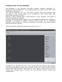
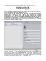
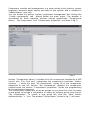
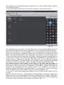
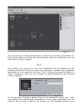
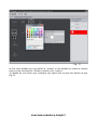
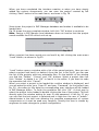
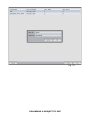
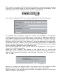
Ilevia S.r.L.
www.ilevia.com
EVE MANAGER USER MANUAL
CONTENTS
1 INTRODUCTION TO EVE MANAGER
2 CREATE A NEW PROJECT
3 USER CREATION AND MANAGEMENT
4 SYSTEM COMPONENT CREATION AND MANAGEMENT
5 SYSTEM SCENARIO CREATION AND MANAGEMENT
6 USER INTERFACE CREATION AND MANAGEMENT
7 SAVE AND LOADING A PROJECT
8 UPLOADING A PROJECT TO EVE
INTRODUCTION TO EVE MANAGER
Eve Manager is the Microsoft Windows systems software (Windows XP,
Windows Vista and Windows 7) for programming the control unit of EVE home
automation supervision.
This manual explains how you can input system data and arrange them
according to the various type of the components and create users and
respective interfaces for EVE
Remote Control (please refer to EVE Remote Control manual). This guide is
mostly intended for installers.
Functions described below assume that the computer wherein the software is
installed is connected to same net where EVE control unit is connected
(through LAN, Internet) or directly connected to EVE with cross cable (please
refer to EVE user manual).
When started the software shows the screen as in Fig. 1
Fig. 1
Interface has 3 operating sections. First one top left is the project management
and Eve programming menu; the second at the right side includes system
components and scenarios and icons for user menu; central area serves to
create and arrange user’s interface for Eve Remote Control panels and
smartphones.
CREATE A NEW PROJECT
To start Eve programming you have first of all to create a new project left
clicking the menu “New project” icon as shown in Fig. 2.
Fig. 2
In the appearing window (fig.3) enter project name in the field “Project Name”
(field is required), EVE control unit IP address (ref. EVE manual) and its name
when you want to separate it from other units of the system. Left click the “OK”
button to confirm or “Cancel” to undo the new project creation.
Fig. 3
The project created is empty and ready for you to add system components.
Now you can select a user associated to the project or create a new user.
USER CREATION AND MANAGEMENT
To create a new user left click the menu “Users” button as in fig. 4.
Fig. 4
User management window includes two sections. On the left the “Users list”
and on the right the details of the selected User.
In this window you can change data the user data, add new users and delete
existing users. Please note that “admin” user described as “System
administrator” is a special user, with privileges allowing the complete
management of all of the system components and users. Administrator cannot
be deleted and is reserved to Eve supervision and maintenance engineers. To
create a new user left click the “New User” button represented by “+” icon and
enter his/her details as shown in fig. 5.
Fig. 5
The box “User ID” is a text field describing the user with a unique name (two
users with the same User ID are not allowed). In the field “Description” you
can enter a free text to describe the user. The “User level” combo box allows
the selection of user privilege level (in other words what the user can do) and
includes the two levels “Master user” and “Standard user”.
A “Master” user can create, cancel and edit standard users and arrange Eve
Remote Control interface by selecting the components included in the system
that are valid for himself and the standard users. A standard user can rearrange its Eve Remote Control interface and change its password (entering
the old one).
The administrator can do all the operations that a master user can, but also
create, edit and cancel the system components.
Once the user level is fixed you must enter the password in the two fields “New
password” and “Confirm new password”.
Now you can confirm user creation left clicking the “Apply” button or undo the
operation left clicking “Cancel”. The new user will appear in “User list”. To edit
user data left click a user in the list and enter new data as described. For
deleting a user, select it and left click the symbol “-” placed under “User list”.
To duplicate a user left click the dot at the left of “-” button. It will duplicate the
interface associated to the user and is very useful when you want to create a
new user maintaining the features of an existing user, when you want, for
instance, to add or delete some components in the interface.
To close “Users” window left click “Close” button.
SYSTEM COMPONENT CREATION AND MANAGEMENT
Component creation and management is a step carried out by electric system
engineers informed about nature and data of the system and is allowed to
“Administrator” user only.
You can access the electric system component management left clicking the
“Create components” tab placed below the main menu. The window is
constituted by three separate sections named respectively “Components
library”, “My components” and “Component's properties” as shown in fig. 6.
Fig. 6
Section “Components library” includes all of the components handled by a EVE
control unit. The “tool box” categorizes the components (switches, sliders,
shutters, …) while the item “All components” shows all of the components
supported in one list. Section “My components” displays the components
created while the section “Component's properties” shows the programming
for the selected component.
The components created are set up as groups so you have first of all to create
a new group to include a component or select an existing group from the list
“My components”. To create a new group left click the “New” button
represented by “+” icon. The window “Group Name” shown in fig. 7, will open.
Fig. 7
Enter a name for the group of components to be created and push “Apply” to
confirm or “Cancel” to undo the operation. You can always delete the group or
the added components by left clicking the button with “-” icon at the left of the
button used to create the group.
Now you can start adding components to the created group by selecting them
in the left list and dragging & dropping them in the tool box of the group in
“My components” section. Fig. 8 shows the adding of a Switch, a Shutter and a
Slider.
Fig. 8
In the “Component's properties” section you can assign the component’s
properties of the component selected in “My components”. In the example of
Fig. 8 the properties of a Switch are set up. In the field “Name” the name you
want to call the component must be entered. For a switch that must turn on or
off a light, you can assign a name reminding the electric system real
component, e.g. “living room light”. For every component an operating
protocol must be set up according to brand/model in use.
Fig. 8 describes the configuration of a “Konnex” switch but different protocols
can be chosen for “Vimar”, “Bticino”, “TCP Modbus” components, etc. Eve
system has been designed to allow the control of a hybrid electric system
including different components using different protocols. You can for instance
control a system with both Konnex and Vimar components. The fields
“Feedback address” and “Write address” (highlighted in fig. 8) must be
carefully completed entering the real details of the device. In the example of
the Konnex switch they must be the same entered in ETS3 software for the
programming of the components used in the electric system. Every component
entered whether switch, slider, RGB Light or others shall have rating values
and properties equal to those of the building electric system. Type and number
of the Feedback/Write fields varies according to type of component and
managing protocol. For further details please refer to installed component user
manual and/or programming software of the component.
The “Flag” “Reversed value (0 = ON, 1 = OFF)” allows to reverse the normal
operation of the switch. If “Reversed value” is checked, the value “ON” will
pass the information “disabled” and vice-versa (the contrary of standard
operation when the value “ON” reflects the information “enabled”).
When you have completed the set up of the values left click the “Apply” button
on the bottom of properties section to store entered data.
In “My components” list the components included but not set up with their
properties are highlighted in red (shutter and slider in fig.8). These components
are still available to be programmed but cannot be used in the user interface
until their properties are set up.
SYSTEM SCENARIO CREATION AND MANAGEMENT
Scenario creation and management is a step carried out by electric system
engineers informed about nature and data of the system and is allowed to
“Administrator” user only.
To access scenario management window left click the tab “Create scenaries”.
It’s a window similar to components creation window and has three sections
named “Scenaries Icons”, “My scenarios” and “Scenarios' properties”.
Ref. fig. 9.
Fig. 9
Section “Scenarios Icons” includes graphic icons associable to a scenario and
are grouped by categories while the tool box “All Icons” is a list of the available
icons.
As in component creation you have to create a group in the list “My scenarios”.
Left click the “+” button and enter the group name, then left click “Apply” to
confirm. Once you have selected the tool box of the group in section “My
scenaries” you can select an icon and drag & drop it within the group. As it is
for components, when you select the added icon, its properties appear in the
section “Scenaries' properties”. Here you must enter a name, select a protocol
and enter number value in the field “Write address”. The field “Write address”
must correspond to the scenario set up in Konnex system. To store entered
data left click “Apply” button below “Scenaries' properties”.
USER INTERFACE CREATION AND MANAGEMENT
This stage let you arrange system components in a user friendly logic interface
Eve Remote Control.
To go to interface editor left click the tab “interface” as shown in fig.10.
Fig. 10
This window has two sections. On the left there is the interface editor while on
the right side there are the lists of available icons, components and scenarios.
Editor (on the left) is in turn divided in four sub-sections representing depth
level you can browse in inside the interface. First level let you create the main
menu. Second level permits you to associate a sub-menu to a main menu icon.
Third level allows you to associate a window containing system components to
a menu icon. Finally, the fourth level permits to associate a sub-window to a
component of a higher level window. This latter too, can include one or more
system components. This logical division is usually used for organizing building
system by rooms or functions. These concepts are better explained below.
To create the main menu select “Icons” tab on the right side as shown in
fig.10, then select an icon from the list and drag & drop it to the upper part of
the editor so that the chosen icon appears in the editor. Repeat this step for
further icons according to the chosen logic. If, by instance, you want to
organize system functions by building room, you can add an icon for the living
room, another one for the kitchen, one or more for bedrooms, etc.
In the fig. 10 two icons have been added, one for a living room and one for a
car box.
Now you can left click the “Components” tab and display in the right side of the
editor the list of the components previously included in the system. When you
select an icon in the main menu you can drag & drop one or more component
of the list to the third level of the editor, as shown in fig. 11.
Fig. 11
Following the example, when you will use Eve Remote interface and left click
the “Living Room” icon, the relative window will open including the controls for
the “light”, “light intensity” and “thermostat” component.
You can add a sub-window containing additional controls to a control in a
window. Just select the component icon to which you want to associate the new
window and drag & drop it from “Components” tab to the last editor level (the
lower one).
In the example illustrated in fig.12 a timed thermostat is associated to the
thermostat of the previously created window.
In this way left clicking the extension button of the thermostat component
inside Eve Remote Control, a window will open including the associated timed
thermostat.
Fig. 12
You can rename, change some features or delete any interface components. To
this purpose when you place the mouse pointer over the component icon, the
icons shown in fig.13 appear.
Fig.13
Left clicking the recycle bin icon the component will be deleted by the
interface, while left clicking the other icon with gears a window with properties
associated to the component will open. Fig. 14 shows the property window of
“light” component. Here you can change the name displayed in Eve Remote
Control interface.
Fig. 14
For the purpose of giving a deeper logic to the interfaces created, you have
seen before that sub-windows associated to every used components can be
created. This concept is valid for the menus, too. EVE Manager permits, as a
matter of fact, to create sub-menu. Just select a main menu icon and drag &
drop another icon from “Icons” or “Scenarios” lists to the second editor level.
Fig.15 shows that the “Sign” icon has been added to the main menu and a submenu containing the scenarios “open all” and “close all” was associated to it.
Now, when you left click “Sign” icon on Eve Remote Control, the new menu
opens and you can select one of the “close all” or “open all” scenarios.
Fig. 15
As for components you can open the property window of icons.
Fig. 16
Just place the mouse pointer over the icon you want to edit the properties to,
and the buttons of Fig.13 will appear. Left click then the gears button. Fig. 16
displays the “open all” icon property window. You can change name and color
every icons have in Eve Remote Control interface. By simply left clicking the
“Name” field you can enter the new name. To change the color left click the
color box at the right hand of “Icon Color” and a window will open for selecting
the color as shown in Fig. 17.
Fig. 17
In this color window you can select a “preset” in the palette or create a custom
color by left clicking the “Define custom color” button.
To delete an icon from user interface just select the recycle bin button as per
Fig.13.
SAVE AND LOADING A PROJECT
When you have completed the interface creation or when you have simply
added the system components, you can save the project created by left
clicking “Save” button in the main menu, as shown in Fig. 18.
Fig. 18
Save stores the project in EVE Manager database and makes it available to be
loaded later.
Fig.19 shows the save complete window. Left click “OK” button to continue.
Note: Saving in EVE Manger local database does not involve that the project
saved modifies the EVE control unit set up.
Fig. 19
When a project has been saved you can load it by left clicking the main menu
“Load” button, as shown in Fig.20.
Fig. 20
“Load” button opens a window with a list of the saved projects. Here you can
select a project and load it or delete it from the list. In the fig.21 you can see
the list of the projects with two selectable files. On the bottom of the window
you find the “Delete”, “Cancel” and “OK” buttons. Select a project then left
click “Delete” to delete it or “OK” to load it in the editor. If you want to undo
the operation left click “Cancel”.
When you select a project to be loaded the confirm window is displayed, and
you are asked to enter your “User ID” and your “Password” for the project (see
fig. 21). According to this data the corresponding user interface will be loaded
in EVE Manager editor. To finish the operation left click “OK”. A short way to
select the project to be loaded is double clicking the line of the project. This will
directly open the window asking for user ID and password. In the fig. 21 you
can see that the test project is selected and in login box the user is “admin”.
Administrator is the sole user allowing the complete management of system
components so it must be used very carefully. Usually this user is chosen by
engineers to make changes to system configuration.
Fig. 21
UPLOADING A PROJECT TO EVE
The upload of a project to EVE allows the interfaces created to become up and
running, so you will be able to use Eve Remote Control for the building. In the
fig.22 the main menu “Upload to EVE” button is highlighted
Fig. 22
Left clicking “Upload to EVE” the window displayed in Fig. 23 will appear.
Fig. 23
In the field “Eve IP Address” enter Eve control unit IP address. This address
could be the local one of the building net or the static IP address supplied by
the operator when you access the system from outside. The field “User ID”
must be completed with the name of one of the users created with EVE
Manager while in the field “User Password” enter the password corresponding
to the user entered. “admin” user is the sole having the power to upload the
electric system components or to edit their setup. All other users can be called
up to change Eve Remote Control interfaces only.
To finish the upload left click “Upload” button as highlighted in the Fig.23 or
“Cancel” to undo the operation.
When you click “Upload” the window of the Fig.24 asks to confirm the
operation. There is a notice that the upload can take even a long time; usually
with a local connection the time is not that long. Left click “Yes” to confirm or
“No” to undo.
Fig. 24
When you confirm the upload to EVE, the system check the integrity of data
and starts the upload. A window with a progress bar will be displayed.
While the work is in progress another window can appear asking to confirm you
want to continue, as per fig.25.
Fig. 25
This is the case when in EVe there is already a project and the updating or the
uploading of the new project are performed from a PC different from the one
where the previous project was created.
Every project created in Eve Manager is identified by a GUID ( Globally Unique
Identifier). In the example the GUID of the project already in EVE does
not match the GUID of the project in upload. Eve Manager asks you,
therefore, to confirm the data upload by left clicking “Yes” or to undo left
clicking “No”. If you continue previous project data will be finally
cancelled. Normal answer here is “Yes”, to continue and complete the
operation.
If you want to edit a project loaded in EVE but you don’t have in local
database of Eve Manger a copy of the project stored, you can ask the
EVE unit for the current project. Just left click “Download from EVE”
button as highlighted in fig. 26.
Fig. 26
The steps to complete the operation are similar to those described for
the upload. Notably a window will appear asking data for the login. Make
reference to the fig. 23 to enter correct data, i.e. EVE IP address, “User
ID” and “Password”. When you confirm the operation left clicking
“Download” a new window will open with the progress bar that gives a
visual status of the progress of the operation. When the download is
complete you have in EVE Manager the interface and the system
components according to the login effected and you can, therefore, edit
and save the project locally and upload again the changes to EVE.
For any question you can contact Ilevia technical assistance using our
email address: [email protected]