1
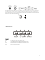
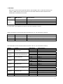
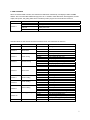
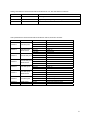
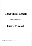
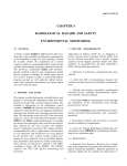
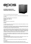
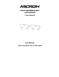
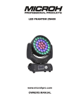
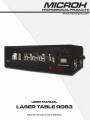
TABLE OF CONTENTS
1. INTRODUCTION AND UNPACKING
1
2. SAFTEY INSTRUCTIONS
1-2
3. OPERATION INSTRUCTIONS
3
4. MOUNTING AND INSTALLATION
4
5. DMX-512 CONTROL CONNECTIONS
4-5
6. MENU NAVIGATION
5
7. ILDA MODE
6
8. DMX CHANNELS
7-8
9. KEY FEATURES
9
10. TECHNICAL SPECIFICATIONS
9
11. ILDA 25 PIN SPECIFICATIONS
9
12. INSTRUCTIONS FOR SCANNER
10
13. INSTRUCTION OF ADJUSTABLE MIRROR HOLDER
11
14. TROUBLESHOOTING
12
15. MAINTENANCE AND CLEANING
13
1. INTRODUCTION AND UNPACKING
Thank you for purchasing the MICROH LASER TABLE 3W laser system. For your own safety and knowledge, please read this
manual before installing or operating the device. This manual covers the important information on installation and applications.
Please install and operate the fixture according to instructions. Meanwhile, please keep this manual for future reference.
The MICROH LASER TABLE 3W laser is made of a new type of high temperature cast aluminum casing. The fixture is designed
and manufactured strictly following CE standards, complying with international standard DMX512 protocol. This fixture is applicable
but not limited to large-scale live performances, theater, studio, nightclubs and discos.
The MICROH LASER TABLE 3W laser system uses 3 coloured laser diodes that are carefully aligned with the internal scan mirrors.
Please carefully unpack it when you receive the fixture and check if it was damaged during the transportation. And please check
whether the following items are included inside the box:
Fixture – One
Power Cord – One
DMX Signal Cable – One
Key – One
Compact Reflector Mirrors – Eight
User Manual – One
2. SAFETY INSTRUCTIONS
This device has left the factory in perfect condition. In order to maintain this condition and to ensure safe operation, it is absolutely
necessary for the user to follow the safety instructions and warning notes written in this user manual.
If the device has been exposed to temperature changes, do not switch it on immediately. The arising condensation could damage
the device. Leave the device switched off until it has reached room temperature, and is dry.
1 This device falls under protection-class I, therefore it is essential that the device be grounded. The electrical connection must be
carried out by a qualified technician.
The device should only be used with rate voltage and frequency. Make sure that the available voltage is not higher than 120V as
stated at the end of this manual.
Make sure the power cord is never crimped or damaged in any way, as this could cause shock and damage. If your power chord is
damaged in any way, please purchase a new cable from your local MICROH dealer. Always disconnect power, when the device is
not in use or before cleaning it. Never pull out the plug by tugging the power cord.
During initial start-up, some smoke or smell may arise. This is a normal process, and does not necessarily mean that the device is
defective. It should decrease gradually. Please do not project the beam onto combustible substances.
Fixtures cannot be installed on or near combustible substances. Keep more than 50cm distance from wall for proper ventilation and
air flow. If your fixture is or has become damaged in any way, it shall be exclusively replaced or repaired by the manufacturer to
avoid any hazard.
To be installed on a fixed flat surface in a level position. Prevent this product from strong vibration or impact. Do not use under
shaking conditions.
Do not turn on this fixture frequently, as it will shorten the life of the laser diodes. THIS
UNIT REQUIRES A DUTY CYCLE
OF 15 MINUTES EVERY 2 HOURS.
Class 4 is the highest and most dangerous class of laser, including all lasers that exceed the Class 3B
AEL. By definition, a class 4 laser can burn the skin, or cause devastating and permanent eye damage as a result of
direct, diffuse or indirect beam viewing. These lasers may ignite combustible materials, and thus may represent a fire
risk. These hazards may also apply to indirect or non-specular reflections of the beam, even from apparently matte
surfaces—meaning that great care must be taken to control the beam path. Class 4 lasers must be equipped with a
key switch and a safety interlock. Most industrial, scientific, military, and medical lasers are in this category, notably
those at the US National Ignition Facility.
2 3. OPERATION INSTRUCTIONS
- Do not turn on the fixture if it has been through severe temperature differences. Damage may occur to the fixture. Wait
until unit is at room temperature to operate.
- The unit should be protected from any tremor or agitation during transport.
- Do not expose the fixture in any excessive heat, moisture or any environment with too much dust when installing. Do not
lay any power cables on the floor. It may cause electronic shock or damage to persons or equipment.
- Make sure to attach the safety chain and ensure the screws are properly screwed in when installing the fixture.
- Make sure the lens is in good condition. It is recommended to replace the unit if there are any damages or severe
scratches.
- Make sure the fixture is operated and installed by qualified personnel.
- Keep the original packaging in case of defective product.
- Any non-manufacturer additions, modifications or changes in any way will void all warranty.
- Please do not attempt to open unit. It is only to be serviced by an authorized technician. If this occurs, or is apparent, the
warranty will be voided.
- The fixture’s warranty will be voided if there are any malfunctions from not following the user manual or any illegal
operation (shock short circuit, electronic shock, lamp broke, etc.)
AUTO-RUN MODE
-
To run the LASER TABLE 3W in AUTO mode, you must set the unit to “AUTO-PLAY” using the on board menu and
Once selected, press ENTER to confirm.
Also, DMX address has to be set to 000 or 0001.
SOUND ACTIVE MODE
-
To run the LASER TABLE 3W in sound active mode, you must set the unit to “AUDI” using the on board menu. Once
selected, press ENTER to confirm.
Also, DMX address has to be set to 000 or 0001.
DMX MODE
-
To control the LASER TABLE 3W via DMX, select “dxxx” on the display. By using the UP and DOWN buttons select
your desired DMX address and press ENTER to confirm. The TITAN RGB has a total 12 channels of DMX.
ILDA (PC CONTROL) MODE
-
To run the LASER TABLE 3W in IDLA mode or (PC CONTROL MODE) simply connect your ILDA signal cable to the
DB25 jack located on the rear of the unit, and the unit will automatically recognize. NOTE: when ILDA is connected, it
supersedes all modes.
3 4. MOUNTING AND INSTALLATION
Caution: For added protection, mount the fixtures in areas outside walking paths, seating areas, or in areas were the fixture might
be reached by unauthorized personnel. Before mounting the fixture to any surface, make sure that the installation area can hold a
minimum point load of 10 times the device’s weight. Fixture installation must always be secured with a secondary safety attachment,
such as an appropriate safety cable. Never stand directly below the device when mounting, removing, or servicing the fixture.
Laser Table has to be set on a flat level surface (see illustration below). Be sure this fixture is kept at least 1m (3.3 ft) away from any
flammable materials (decoration etc.). Always use and install the supplied safety cable as a safety measure to prevent accidental
damage and/or injury in the event the clamp fails.
Mounting Points: Overhead mounting requires extensive experience, including calculating working load limits. A knowledge of the
installation material being used, and periodic safety inspection of all installation material and the fixture are all imperative and should
only be performed by a qualified technician. Improper installation can result in bodily injury and damage.
Be sure to complete all rigging and installation procedures before connecting the main power cord to the appropriate wall outlet.
Regardless of the rigging option you choose for your MICROH LASER TABLE 3W fixture, always be sure to secure your fixture with
a ratchet strap. Please see picture below.
5. DMX-512 CONTROL CONNECTIONS
This fixture complies with international USITT DMX standards and can be used with either a 3 pin or 5 pin DMX connector. Plug in
the provided 3 pin XLR cable to the female 3-pin XLR output of your controller and the other side to the male 3-pin XLR input of the
MICROH LASER TABLE 3W. To connect the units to DMX, you must daisy chain the fixtures together as referred in the diagram
below. Always end your DMX-512 connection with a DMX terminator.
4 For installations where the DMX cable has to run a long distance, or is in an electrically noisy environment, it is recommended to
use a DMX terminator. This helps in preventing corruption of the digital control signal by electrical noise. The DMX terminator is
simply an XLR plug with a 120 Ω resistor connected between pins 2 and 3,which is then plugged into the output XLR socket of the
last fixture in the chain. Please see illustrations below.
120Ω
2
3
1
PIN 3
PIN 2
6. MENU NAVIGATION
FUNCTIONS
Mode:
Auto, DMX & Sound Active. Press ENTER to confirm.
Up:
Increase DMX Address (Under DMX Mode) Press ENTER to confirm.
Down:
Decrease DMX Address (Under DMX Mode) Press ENTER to confirm.
Enter:
Press when confirming any setting.
5 7. ILDA MODE
When laser connects to PC through ILDA interface, LCD will display “ILDA”; to have total control by ILDA
interface, a DMX controller must be connected to a Laser Table and the first channel should be set to
Animation/PC mode between 192 and 255.
Channel
Channel 1
DMX Address
Control Content
0~63
Sheltering mode
64~127
Grating lens mode
128~191
192~255
Laser point mode
PC control mode
PC control mode: Laser brightness and scanner output are controlled by computer.
Grating Lens Mode: the first channel should be set between 64~127, see chart below for reference:
Channel
DMX Address
Control Content
Channel 2
10~255
Select gobos
Channel 3
0~255
Adjust the speed of grating lens rotating
Channel 4
0~255
Select colour
Laser Point Mode: the first channel should be set between 128~191, see chart below for reference:
Channel
Function
Channel 2
First laser point
Channel 3
First laser point divided into two
Channel 4
Second laser point
Channel 5
Second laser point divided into
two
Channel 6
Third laser point
Channel 7
Third laser point divided into two
Channel 8
Forth laser point
Channel 9
Channel 10
Adjust speed
Colour
DMX Address
0~60
61~119
120~255
0~60
61~119
120~255
0~60
61~119
120~255
0~60
61~119
120~255
0~60
61~119
120~255
0~60
61~119
120~255
0~60
61~119
120~255
0~255
0--255
Control Content
Laser off
Laser on
Strobe flash
Laser off
Laser on
Strobe flash
Laser off
Laser on
Strobe flash
Laser off
Laser on
Strobe flash
Laser off
Laser on
Strobe flash
Laser off
Laser on
Strobe flash
Single laser point
Double laser point
Strobe flash
Control the speed of strobe
Select colour
6 8. DMX CHANNELS
When connected to DMX controller, laser will switch to DMX mode automatically. LCD displays “DMX” and DMX
address. User can select DMX address through press “UP” or “DOWN”. Under DMX mode, laser brightness, scanner
output, laser pointer, and grating effect will be controlled by built-in program. See chart below for reference:
Channel
Channel 1
DMX Address
0~63
64~127
Control Content
Sheltering mode
Grating lens mode
128~191
Laser point mode
192~255
Animation mode
Animation Mode: the first channel should be set between 0~63. See chart below for reference:
Channel
Function
DMX Address
Channel 2
Gobos
0-255
Channel 3
Strobe flash
0-10
11-255
No strobe flash
Auto strobe flash
0-125
126-185
186-225
226-255
0-125
126-185
186-225
226-255
0-10
Hand adjustment position
Auto left-right cycle
Auto jumping left-right cycle
Auto jumping
Hand adjustment position
Auto up-down cycle moving
Auto jumping up-down cycle
Auto jumping
No zoom in/out
11-100
101-150
151-200
201-255
0-10
11-110
111-255
0-10
11-110
111-255
0
1-180
181-217
218-255
0-74
75-104
105-180
180-255
Hand adjustment size
Zoom in
Zoom out
Zoom in/out
No rotating
Hand adjustment
Auto rotating
No rotating
Hand adjustment
Auto rotating
No rotating
Hand adjustment
Auto clockwise rotating
Auto counter-clockwise rotating
Hand adjust printing gradually
Auto printing gradually(add)
Auto printing gradually(reduce)
Auto cycle printing gradually
0--255
Select colour
Channel 4
Channel 5
Level moving
Vertical moving
Channel 6
Zoom in/out
Channel 7
X axis rotating
Channel 8
Channel 9
Y axis rotating
Z axis rotating
Printing gradually
Channel 10
Channel 11
Colour
Control Content
Select gobos
7 Grating Lens Mode: the first channel should be set between 64~127. See chart below for reference:
Channel
DMX Address
Control Content
Channel 2
10~255
Select gobos
Channel 3
Channel 4
0~255
0~255
Adjust the speed of grating lens rotating
Select colour
Laser point Mode: the first channel should be set between 128-191,its function as below:
Channel
Function
Channel 2
First laser point
Channel 3
First laser point
divide into two
Channel 4
Second laser point
Channel 5
Second laser point
divide into two
Channel 6
Third laser point
Channel 7
Third laser point
divide into two
Channel 8
Forth laser point
Channel 9
Channel 10
Adjust speed
Colour
DMX Address
0~60
61~119
120~255
0~60
61~119
120~255
0~60
61~119
120~255
0~60
61~119
120~255
0~60
61~119
120~255
0~60
61~119
120~255
0~60
61~119
120~255
0~255
0~255
Control Content
Laser off
Laser on
Strobe flash
Laser off
Laser on
Strobe flash
Laser off
Laser on
Strobe flash
Laser off
Laser on
Strobe flash
Laser off
Laser on
Strobe flash
Laser off
Laser on
Strobe flash
Single laser point
Double laser point
Strobe flash
Control the speed of strobe
Select colour
8 9. KEY FEATURES
- RGB Colour Mixing DPSS Diodes (Red650nm, Green 532nm, Blue455nm)
- On-Board Digital Display
- Controllable via DMX (3 Pin XLR)
- IDLA Input for PC Control
- High Speed Quality 30K Scan Motors (Max 30,000 pps)
- 3W Total Laser Output (Red 1W + Greed 1W + Blue 1W)
- DMX, ILDA, Sound Active, Auto,
- 4, 10 or 11 DMX Channels
10. TECHNICAL SPECIFICATIONS
MODEL: LASER TABLE 3W
LASER DIODE: DPSS, Red650nm, Green 532nm, Blue455nm
SCANNER: 30 Kpps
SCANNING ANGLE: ± 30°
COOLING SYSTEM: Fan
MAX RUN TIME: Approximately 4 Hours
WARM-UP TIME: < 15 Minutes
WORKING TEMPERATURE: 10° ~ 35° C
VOLTAGE: 120VAC 60Hz
FUSE: 3A/250V
DIMENSIONS: 32.87" x 16.93" x 9.21" / 835 x 430 x 234 mm
CASE DIMENSIONS: 39.37” x 20.47” x 16.54” / 1000 x 520 x 420 mm
NET WEIGHT: 57.4 lbs / 26.04kgs
GROSS WEIGHT: 108.6lbs / 49.26kgs
WARRANTY: 2 Year Limited Warranty. The Laser diodes are covered under a 6 month replacement warranty.
11. ILDA 25 PIN SPECIFICATIONS
1
2
3
4
5
6
7
8
9
10
11
12
13
X+
Y+
No Function
Interlock A
Red+
Green+
Blue+
No Function
No Function
No Function
No Function
No Function
No Function
14
15
16
17
18
19
20
21
22
23
24
25
XYNo Function
Interlock B
RedGreenBlueNo Function
No Function
No Function
No Function
Ground
9 12.INSTRUCTIONS FOR SCANNER
Below is scanner photo:
1. Scanner base
2.X axis hex socket cap screws
3. Y axis mirror
4. X axis mirror
5. Y axis hex socket cap screws
6.Y axis dynamo and wire connector
7.X axis dynamo and wire connector
By unscrewing X/Y axis hex socket cap screws to adjust X/Y axis dynamo angle to make laser beam on the centre of lens. And
then tighten up the X/Y axis screws.
10 13.INSTRUCTION OF ADJUSTABLE MIRROR HOLDER
Below is photo of the parts for adjusting the laser beam
1.Mirror on motor
2.Mirror holder on motor
3.Down blade on motor in black color
4.Upper blade on motor in black color
5.Motor screw
6.Motor
7.Reflector lens holder
8.Reflector lens support
9.Reflector lens
- Set laser under sound mode, and adjust sound MIC to MIN. By this way, there is no sound signal for lasers and laser stop working.
- Loosen the reflector holder screw (the screw for the fix reflector holder is on the base), turn the holder, adjust laser dot at suitable
position, then tighten up the screw.
- Loose two hex socket cap screws which are connect reflector holder and reflector support together, turn reflector support up and
down, adjust laser vertical height to suitable place you want, then tighten up the screw.
- During adjustment, if light on motor mirror, please turn the mirror by hand to make light not on the mirror. When adjust all light
beam at suitable place you want, adjust sound knob at suitable place, turn on power. It will work well.
- Please don’t move or adjust parts NO. 1.2.3.4.5.6.. These Parts can be adjusted only by specialist. Because it is only laser pointer
output when adjustment, please don’t see the laser dot directly for safety reason.
11 14. TROUBLESHOOTING
Fault
Reasons
Solution
Fuse defective
REPLACE fuse
Four foot switch bad
REPLACE switch
Power socket not connected well
REPLACE power socket /power cable
12 PIN wire faulty
REPLACE 12 PIN wire
LCD Display no light,no
LCD Display faulty
REPLACE LCD Display
display
Red/black wire didn’t connect into 5V
Connect into 5V and turn on power
12V fan faulty
REPLACE fan
Something stuck in the fan
Remove debris
12V power supply faulty
REPLACE 12V power supply
Not under sound control mode
Adjust to sound control mode
Sound knob adjust at MIN
Adjust sound knob at center place
Motor not working, or
12V power supply faulty
REPLACE 12V power supply
rotation slow, but other parts
Motor driver IC faulty
REPLACE 2803
work well
Main IC faulty
REPLACE main IC(STC11F60XE)
Optical scanner faulty
REPLACE optical scanner
X/Y axis doesn’t move or
±15V power supply faulty
REPLACE±15V power supply
scanner jumping
Signal switch board faulty
REPLACE signal switch board
Scanner main board faulty
REPLACE scanner main board
DC motor faulty
REPLACE DC motor
Power supply faulty
REPLACE ±5V power supply
Transformer faulty
REPLACE transformer
DC motor driving board faulty
REPLACE driving board fault
DMX address for laser not equal to the
Reset DMX address
No power
LCD Display has light, no
display
Fan not working, other is fine
No sound control
DC motor no rotation or no
gobo, other parts work well
Cannot control DMX
Under ILDA mode, animation
is faulty, others are fine
No light or light is dark,
others are fine
address for controller
Analog switch IC faulty
REPLACE IC(DJ413)
Main IC faulty
Main IC(STC11F60XE)
Signal switch board faulty
REPLACE signal switch board
Power off
Turn on power supply
Mirror dirty
Clean the mirror
Laser diode faulty
REPLACE laser diode
12 15. MAINTENANCE AND CLEANING
The following points have to be considered during the inspection:
1) All screws for installing the device or parts of the device must be tightly connected, and must not be corroded.
2) There must not be any deformations on the housing, colour lenses, fixations or installation spots (ceiling, suspension, trussing).
3) Mechanically moved parts must not show any traces of wearing and must not rotate with unbalances.
4)The electric power supply cables must not show any damage, material fatigue or sediments.
Further instructions depending on the installation spot and usage must be handled by a skilled installer or technician. Any safety
issues must be resolved.
In order to keep the fixture in good condition and extend the life, we suggest regular cleaning to the fixture.
1) Clean the inside and outside lens each week to avoid the light output from darkening due to accumulation of dust, dirt, etc.
2) Clean the fan each week.
3) A detailed electrical check by approved technician every three months is advised. Ensure the circuit contacts are in good
condition, and prevent from overheating.
We recommend a frequent cleaning of the device. Please use a moist, lint- free cloth. Never use alcohol or solvents.
There are no serviceable parts inside the device. Please refer to the instructions under “Installation instructions”.
Should you need any spare parts, please order genuine MICROH parts from your local dealer.
IF YOU SHOULD EXPERIENCE ANY PROBLEMS OR ISSUES PLEASE CONTACT MICROH PROFESSIONAL PRODUCTS BY
EMAIL AT [email protected]
In the event that your unit is defective in any way, please contact your local dealer to obtain an RA number for service
repair.
DISCLAIMER – MICROH believes that the information contained within this user manual is accurate. However, Microh is
not responsible for any error or addendums to this manual. If you have any comments or general suggestions on how this
manual can be improved please contact [email protected]. Thank you.
13