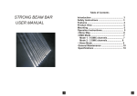
1
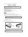
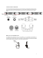
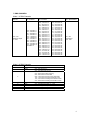
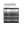
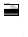
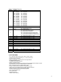
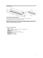
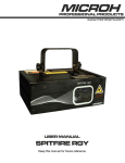
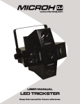
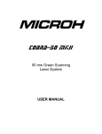
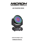
TABLE OF CONTENTS
1. INTRODUCTION AND UNPACKING
1
2. SAFTEY INSTRUCTIONS
1-2
3. OPERATION INSTRUCTIONS
2-5
4. MOUNTING AND INSTALLATION
5
5. DMX-512 CONTROL CONNECTIONS
6
6. MENU NAVIGATION
7
7. DMX CHANNELS
8-11
8. KEY FEATURES
11-12
9. TECHNICAL SPECIFICATIONS
12
10. UNIT OVERVIEW
13
11. MAINTENANCE AND CLEANING
14
1. INTRODUCTION AND UNPACKING
Thank you for purchasing the MICROH LED Razor45 high power RGBAW wash. For your own safety and knowledge,
please read this manual before installing or operating the device. This manual covers the important information on
installation and applications. Please install and operate the fixture according to instructions. Meanwhile, please keep this
manual for future reference.
The MICROH LED Razor45 wash is made of a new type of high temperature strength of engineering plastics and cast
aluminum. The fixture is designed and manufactured strictly following CE standards, complying with international standard
DMX512 protocol. This fixture is applicable but not limited to large-scale live performances, theater, studio, nightclubs and
discos.
The MICROH LED Razor45 utilizes 45 x 1.2W Edison powerful LEDs, which feature high brightness and stability. Please
carefully unpack it when you receive the fixture and check if it was damaged during the transportation. And please check
whether the following items are included inside the box:
Fixture - One
Power Cable - One
User Manual – One
2. SAFTEY INSTRUCTIONS
This device has left the factory in perfect condition. In order to maintain this condition and to ensure safe operation, it is
absolutely necessary for the user to follow the safety instructions and warning notes written in this user manual.
1
If the device has been exposed to temperature changes, do not switch it on immediately. The arising condensation could
damage the device. Leave the device switched off until it has reached room temperature, and is dry.
This device falls under protection-class I, therefore it is essential that the device be grounded. The electrical connection
must be carried out by a qualified technician.
The device should only be used with rate voltage and frequency. Make sure that the available voltage is not higher than
120V as stated at the end of this manual.
Make sure the power cord is never crimped or damaged in any way, as this could cause shock and damage. If your power
chord is damaged in any way, please purchase a new cable from your local MICROH dealer. Always disconnect power,
when the device is not in use or before cleaning it. Never pull out the plug by tugging the power cord.
During initial start-up, some smoke or smell may arise. This is a normal process, and does not necessarily mean that the
device is defective. It should decrease gradually. Please do not project the beam onto combustible substances.
Fixtures cannot be installed on or near combustible substances. Keep more than 50cm distance from wall for proper
ventilation and air flow. If your fixture is or has become damaged in any way, it shall be exclusively replaced or repaired
by the manufacturer to avoid any hazard.
3. OPERATION INSTRUCTIONS
-
Do not turn on the fixture if it has been through severe temperature differences. Damage may occur to the
fixture. Wait until unit is at room temperature to operate.
-
The unit should be protected from any tremor or agitation during transport.
-
Do not expose the fixture in any excessive heat, moisture or any environment with too much dust when
installing. Do not lay any power cables on the floor. It may cause electronic shock or damage to persons or
equipment.
-
Make sure to attach the safety chain and ensure the screws are properly screwed in when installing the fixture.
-
Make sure the lens is in good condition. It is recommended to replace the unit if there are any damages or
severe scratches.
-
Make sure the fixture is operated and installed by qualified personnel.
-
Keep the original packaging in case of defective product.
-
Any non-manufacturer additions, modifications or changes in any way will void all warranty.
-
Please do not attempt to open unit. It is only to be serviced by an authorized technician. If this occurs, or is
apparent, the warranty will be voided.
2
-
The fixture’s warranty will be voided if there are any malfunctions from not following the user manual or any
illegal operation (shock short circuit, electronic shock, lamp broke, etc.)
-
This fixture is equipped with 5 operating modes; DMX, Auto, Sound Active, Master/Slave and Program.
DMX
In DMX mode, you have 5 modes to select according to programming requirement for your environment: 4ch, 8ch, 21ch,
48ch and 49ch mode.
1. Press MENU button to go to System Mode, then use Up/Down button to select System Mode [DMX] and press Fun
button to enter and LCD displays:
Addr mode ID
[001] 1 1
2. Use Fun button to move among [Addr, Mode, ID] and Up/Down button to set up starting DMX address, Mode and ID
number.
Addr mode ID
[006] 3 1
NOTE: ID number is activated only when Mode 5 is selected. Under Mode 1~4, ID number is invalid.
DMX CONTROL WITH ID NUMBER
ID number is created for DMX fixture with large number of DMX channels and allows one to control multiple units
independently or simultaneously on a small DMX console. The figure below shows a simple DMX layout. On the same
starting channel, say 001, there are three units with 3 different ID numbers. You can use the 1st channel to target different
units and backward channels to program.
AUTO MODE
In this mode, you can combine 12 editable, 6 built-in programs and running time of each program without external DMX
controller.
1. Press MENU button till System Mode [xxx] displayed, then use Up/Down button to select System Mode [Auto] and
press Fun button to enter. LCD shows:
Step prog time
[1]
1
020
2. Press Fun button to move forward and Up/Down button to select step (1-18) and Program number (1-18), time (1-240s)
for each step/program.
3. Press MENU button to exit and run in Auto mode.
3
SOUND ACTIVE MODE
1. Press MENU button till System Mode [xxx] displayed, then use Up/Down button to select System Mode [Sound] and
press Fun button to enter. LCD shows:
Sound Program
[xx]
2. Press Up/Down button to select Sound Program [1-16]. [1-12] program is editable and [13-16] program is fixed.
3. When Sound Program [1-12] is selected, press Fun button to enter and use Up/Down to select effects [1-12] (same as
updating), colors [1-50] (same as updating) and set sound sensitivity from [1-99], HIGHEST to LOWEST level.
4. When Sound Program [13-16] is selected, press Fun button to enter and use Up/Down to set sound sensitivity [1-99].
MASTER/SLAVE MODE
In this mode, one can run the whole system in synchronized effect. Maximum 31pcs can be linked in a daisy chain as
Master/Slave operating system.
1. One unit is to be set as Master and this Master unit needs to work under PROGRAM or Auto or Sound mode. Also, you
need to set Slave Number for total number of Slave units. i.e., there are 5 Slave units (not including Master unit) in the
daisy chain, then Slave Number is 5.
2. Other units are to be set in Slave mode and Slave ID is to be set for each Slave unit.
3. Operate the Master unit in PROGRAM, Auto and Sound mode to run the whole system.
In Master/Slave operating mode, all Slave units are to be set to Slave Mode and Slave ID is required for each Slave unit.
1. Press MENU button go to System Mode, then use Up/Down button to select System Mode [Slave] and press Fun
button to enter.
2. Use Up/Down button to set up a Slave ID number for that unit. The first Slave connected with the Master unit is Slave
ID [1], the next Slave units are Slave ID [2], Slave ID [3], and so on.
In Master/Slave mode, in order to run color flow effect sequentially through the daisy chain, on the Master unit you need to
set up a total number for Slave units.
1. Press MENU button till [System Setup] shows up, then use Up/Down button to select System Setup [Slave Number]
and press Fun button to enter.
2. Use Up/Down button to set up the number of total Slave units.
PROGRAM MODE
In this mode, you can edit and run Program Number [1] to [12] combining effect, color, speed to make desired programs.
Program from [13] to [18] are non-editable while you can select appropriate speed to run the program.
1. Press MENU button go to System Mode, then use Up/Down button to select System Mode [Program] and press Fun
button to enter.
2. Use Up/Down button to select program number, then press Fun button to select Program Effect [x], Program Speed [x],
Program Color [x].
4
3. Press Up/Down button to select effect, color and speed for that program.
Note: 1. Effects [1-12] and Colors [1-50] are from factory default settings or customized.
2. Speed 1 ~ 99 goes from fastest to slowest.
► NON editable program 13-18
Program Number [13]: 50-color step changing
Program Number [14]: Color flowing in Red, Green, Blue, White and Amber
Program Number [15]: 50-color crossfade
Program Number [16]: Falling star effect in white color
Program Number [17]: RRGGWBBAA flashing
Program Number [18]: Pulse close effect
TEST MODE
Test Mode is designed to test LEDs and fans if they are all working.
1. Press MENU button till [Test Mode] shows up, press Fun button to enter Test Mode.
2. Use Up/Down button to select [Test LED] or [Test Fan], then press Fun button to go to Test LED or Test Fan.
3. Press Up/Down to test Red, Green, Blue, White and Amber LEDs or test fan ON/OFF.
NOTE! During operating Fans will be turned off when internal temperature is below 40°C and
will be turned on automatically over that level.
4. MOUNTING AND INSTALLATION
This fixture is designed for floor stand and truss mounting.
IMPORTANT!!! Safety cables must always be used. The safety cable must be capable of holding 10
times the weight of the fixture.
5
5. DMX-512 CONTROL CONNECTIONS
Connect the provided XLR cable to the female 3-pin or 5-pin XLR output of your controller and the other side to the male
3-pin or 5-pin XLR input of the MICROH LED PHANTOM. You can chain multiple units together through serial linking. The
cable needed should be a two core, screened cable with XLR input and output connectors. Please refer to the diagram
below.
DMX-512 Connection With DMX Terminator
For installations where the DMX cable has to run a long distance, or is in an electrically noisy environment, it is
recommended to use a DMX terminator. This helps in preventing corruption of the digital control signal by electrical noise.
The DMX terminator is simply an XLR plug with a 120 Ω resistor connected between pins 2 and 3,which is then plugged
into the output XLR socket of the last fixture in the chain. Please see illustrations below.
120Ω
2
3
1
PIN 3
PIN 2
6
6. MENU NAVIGATION
When navigating the menu:
Use “UP” button to move up.
Use “DOWN” button to move down.
Use “FUN” button to move right.
Use “MENU” button to move left.
7
7. DMX CHANNELS
Mode 1: 4 DMX Channels
Ch
1:
Dimmer
Master
000 – 255
Brightness Adjust
0 - 100%
Ch 2: Effects
Ch 3: Colours
000 – 023 Effect 1
024 – 046 Effect 2
047 – 069 Effect 3
070 – 092 Effect 4
093 – 115 Effect 5
116 – 139 Effect 6
140 – 162 Effect 7
163 – 185 Effect 8
186 – 208 Effect 9
209 – 231 Effect 10
232 – 254 Effect 11
255 Effect 12
000 – 005 Colour 1
006 – 010 Colour 2
011 – 015 Colour 3
016 – 020 Colour 4
021 – 026 Colour 5
027 – 031 Colour 6
032 – 036 Colour 7
037 – 041 Colour 8
042 – 046 Colour 9
047 – 052 Colour 10
053 – 057 Colour 11
058 – 062 Colour 12
063 – 067 Colour 13
068 – 072 Colour 14
073 – 078 Colour 15
079 – 083 Colour 16
084 – 088 Colour 17
089 – 093 Colour 18
094 – 098 Colour 19
099 – 104 Colour 20
105 – 109 Colour 21
110 – 114 Colour 22
115 – 119 Colour 23
120 – 124 Colour 24
125 – 130 Colour 25
Ch 4: Speed Effect
131 – 135 Colour 26
136 – 140 Colour 27
141 – 145 Colour 28
146 – 150 Colour 29
151 – 156 Colour 30
157 – 161 Colour 31
162 – 166 Colour 32
167 – 171 Colour 33
172 – 176 Colour 34
177 – 182 Colour 35
183 – 187 Colour 36
188 – 192 Colour 37
193 – 197 Colour 38
198 – 202 Colour 39
203 – 208 Colour 40
209 – 213 Colour 41
214 – 218 Colour 42
219 – 223 Colour 43
224 – 228 Colour 44
229 – 234 Colour 45
235 – 239 Colour 46
240 – 244 Colour 47
245 – 249 Colour 48
250 – 254 Colour 49
255 – 255 Colour 50
000 – 255
Speed Adjust
Slow - Fast
Mode 2: 8 DMX Channels
Channel
1
2
Function
Master Dimmer
Strobe
Effects
3
4
5
6
7
8
Red
Green
Blue
White
Amber
000 – 255 Brightness Adjust 0 – 100%
000 – 004 No Function
005 – 255 Strobe Slow to Fast
000 – 015 No Function
016 – 055 50 Colour Step Changing
056 – 095 50 Colour Cross Fade
096 – 135 50 Colour Flowing From Left to Right
136 – 175 50 Colour Flowing From Right to Left
176 – 215 50 Colour Chasing From Center to Ends
216 – 255 50 Colour Chasing From Ends to Center
000 – 255 Brightness Adjust
000 – 255 Brightness Adjust
000 – 255 Brightness Adjust
000 – 255 Brightness Adjust
000 – 255 Brightness Adjust
0 – 100%
0 – 100%
0 – 100%
0 – 100%
0 – 100%
8
Mode 3: 21 DMX Channels
Channel
1
Function
Master Dimmer
Effects
2
3
4
5
6
7
8
9
10
11
12
13
14
15
16
17
18
19
20
Strobe
Red
Green
Blue
White
Amber
Strobe
Red
Green
Blue
White
Amber
Strobe
Red
Green
Blue
White
Amber
000 – 255 Brightness Adjust 0 – 100%
000 – 015 No Function
016 – 055 50 Colour Step Changing
056 – 095 50 Colour Cross Fade
096 – 135 50 Colour Flowing From Left to Right
136 – 175 50 Colour Flowing From Right to Left
176 – 215 50 Colour Chasing From Center to Ends
216 – 255 50 Colour Chasing From Ends to Center
Section 1
000 – 004 No Function
005 – 255 Strobe Slow to Fast
000 – 255 Brightness Adjust 0 – 100%
000 – 255 Brightness Adjust 0 – 100%
000 – 255 Brightness Adjust 0 – 100%
000 – 255 Brightness Adjust 0 – 100%
000 – 255 Brightness Adjust 0 – 100%
Section 2
000 – 004 No Function
005 – 255 Strobe Slow to Fast
000 – 255 Brightness Adjust 0 – 100%
000 – 255 Brightness Adjust 0 – 100%
000 – 255 Brightness Adjust 0 – 100%
000 – 255 Brightness Adjust 0 – 100%
000 – 255 Brightness Adjust 0 – 100%
Section 3
000 – 004 No Function
005 – 255 Strobe Slow to Fast
000 – 255 Brightness Adjust 0 – 100%
000 – 255 Brightness Adjust 0 – 100%
000 – 255 Brightness Adjust 0 – 100%
000 – 255 Brightness Adjust 0 – 100%
000 – 255 Brightness Adjust 0 – 100%
9
Mode 4: 48 DMX Channels
Channel
1
2
Function
Master Dimmer
Master Strobe
Effects
3
4
5
6
7
8
9
10
11
12
13
.
.
.
46
47
48
LED 1 Red
LED 2 Green
LED 3 Blue
LED 4 White
LED 5 Amber
LED 6 Red
LED 7 Green
LED 8 Blue
LED 9 White
LED 10 Amber
.
.
.
LED 43 Blue
LED 44 White
LED 45 Amber
000 – 255 Brightness Adjust 0 – 100%
000 – 004 No Function
005 – 255 Strobe Slow to Fast
000 – 015 No Function
016 – 055 50 Colour Step Changing
056 – 095 50 Colour Cross Fade
096 – 135 50 Colour Flowing From Left to Right
136 – 175 50 Colour Flowing From Right to Left
176 – 215 50 Colour Chasing From Center to Ends
216 – 255 50 Colour Chasing From Ends to Center
000 – 255 Brightness Adjust 0 – 100%
000 – 255 Brightness Adjust 0 – 100%
000 – 255 Brightness Adjust 0 – 100%
000 – 255 Brightness Adjust 0 – 100%
000 – 255 Brightness Adjust 0 – 100%
000 – 255 Brightness Adjust 0 – 100%
000 – 255 Brightness Adjust 0 – 100%
000 – 255 Brightness Adjust 0 – 100%
000 – 255 Brightness Adjust 0 – 100%
000 – 255 Brightness Adjust 0 – 100%
000 – 255 Brightness Adjust 0 – 100%
000 – 255 Brightness Adjust 0 – 100%
000 – 255 Brightness Adjust 0 – 100%
10
Mode 5: 49 DMX Channels
Channel
1
2
3
Function
(ID# Select)
000 – 008 ID #1
009 – 017 ID #2
018 – 026 ID #3
027 – 035 ID #4
036 – 043 ID #5
044 – 052 ID #6
053 – 061 ID #7
062 – 070 ID #8
071 – 079 ID #9
080 – 087 ID #10
088 – 096 ID #11
097 – 105 ID #12
106 – 114 ID #13
115 – 123 ID #14
124 – 131 ID #15
Master Dimmer
Master Strobe
Effects
4
5
6
7
8
9
10
11
12
13
14
.
.
.
47
48
49
LED 1 Red
LED 2 Green
LED 3 Blue
LED 4 White
LED 5 Amber
LED 6 Red
LED 7 Green
LED 8 Blue
LED 9 White
LED 10 Amber
.
.
.
LED 43 Blue
LED 44 White
LED 45 Amber
132 – 140 ID #16
141 – 149 ID #17
150 – 158 ID #18
159 – 167 ID #19
168 – 175 ID #20
176 – 184 ID #21
185 – 193 ID #22
194 – 202 ID #23
203 – 211 ID #24
212 – 219 ID #25
220 – 228 ID #26
229 – 237 ID #27
238 – 246 ID #28
247 – 254 ID #29
255 – 255 ID #30
000 – 255 Brightness Adjust 0 – 100%
000 – 004 No Function
005 – 255 Strobe Slow to Fast
000 – 015 No Function
016 – 055 50 Colour Step Changing
056 – 095 50 Colour Cross Fade
096 – 135 50 Colour Flowing From Left to Right
136 – 175 50 Colour Flowing From Right to Left
176 – 215 50 Colour Chasing From Center to Ends
216 – 255 50 Colour Chasing From Ends to Center
000 – 255 Brightness Adjust 0 – 100%
000 – 255 Brightness Adjust 0 – 100%
000 – 255 Brightness Adjust 0 – 100%
000 – 255 Brightness Adjust 0 – 100%
000 – 255 Brightness Adjust 0 – 100%
000 – 255 Brightness Adjust 0 – 100%
000 – 255 Brightness Adjust 0 – 100%
000 – 255 Brightness Adjust 0 – 100%
000 – 255 Brightness Adjust 0 – 100%
000 – 255 Brightness Adjust 0 – 100%
000 – 255 Brightness Adjust 0 – 100%
000 – 255 Brightness Adjust 0 – 100%
000 – 255 Brightness Adjust 0 – 100%
8. KEY FEATURES
- 45 x 1.2W Edison LEDs (9 red, 9 green, 9 blue, 9 amber, 9 white)
- 5 DMX Channel Modes ID Addressing: 4, 8, 21, 48 & 49 Channels
- Bright Blue Digital LCD Display
- DMX 512, Master/Slave, Sound Active, Auto & Program Modes
- 50 Updatable Preset Colours
- 12 Editable and Updatable Programs
- 6 Built-in and Fixed Programs
- Onboard Programming Functionality Enables Programming Without External DMX Controller
- Sequential Running and Time Setup of Programs in Stand Alone
- Built-in Automated Programs via Master/Slave or DMX
- Program and Recall Custom Programs via master/slave or DMX
- USB connector for color/effect programs updating through USB device
- Thermal management system ensures long life of LEDs
- Automatic fan speed responding to internal temperature
- 3-pin & 5-pin XLR DMX In/Out
- Factory default reset
- Power failure memory
- 400MHz refresh frequency
11
LENS REPLACMENT - The MICROH RAZOR 45 comes with lens pre-installed at the factory. However, interchangeable
lens system gives you options to change lens of different beam angle. Please follow the below instructions for proper
replacement/installation.
1. Remove all 8 screws from side metal cover.
2. Remove plastic front cover by sliding it out.
3. Remove all 10 screws that hold the lens kit in place and take out the complete lens kit.
4. Replace lens kit and follow reverse steps to close the fixture.
IMPORTANT!!! When replacing the lens assembly, please make sure that the power is disconnected
from the fixture beforehand. LEDs on PCBs are sensitive to ESD (electrostatic discharge). Take
precautions to avoid ESD damage during service.
9. TECHNICAL SPECIFICATIONS
MODEL: LED RAZOR45
LAMP: 45 x 1.2W Edison LEDs (9 Red, 9 Green, 9 Blue, 9 White Edison LEDs)
VOLTAGE: 120VAC 60Hz 114W 0.95A
FUSE: 2A /120VAC
DIMENSIONS: 21.1” x 6” x 8.8” / 511 x 152 x 224 mm
BOX DIMENSIONS: 24.09” x 11.34” x 8.58” / 612 x 288 x 218 mm
NET WEIGHT: 12.55 lbs / 7.3 kgs
GROSS WEIGHT: 16.1 lbs / 11kgs
WARRANTY: 2 Year Limited Warranty
12
10. UNIT OVERVIEW
13
11. MAINTENANCE AND CLEANING
The following points have to be considered during the inspection:
1) All screws for installing the device, or parts of the device must be tightly connected, and must not be corroded.
2) There must not be any deformations on the housing, colour lenses, fixations or installation spots (ceiling, suspension,
trussing).
3) Mechanically moved parts must not show any traces of wearing and must not rotate with unbalances.
4)The electric power supply cables must not show any damage, material fatigue or sediments.
Further instructions depending on the installation spot and usage must be handled by a skilled installer or technician. Any
safety issues must be resolved.
In order to keep the fixture in good condition and extend the life, we suggest regular cleaning to the fixture.
1) Clean the inside and outside lens each week to avoid the light output from darkening due to accumulation of dust,
dirt, etc.
2) Clean the fan each week.
3) A detailed electrical check by approved technician every three months is advised. Ensure the circuit contacts are
in good condition, and prevent from overheating.
We recommend a frequent cleaning of the device. Please use a moist, lint- free cloth. Never use alcohol or solvents.
There are no serviceable parts inside the device. Please refer to the instructions under “Installation instructions”.
Should you need any spare parts, please order genuine MICROH parts from your local dealer.
IF YOU SHOULD EXPERIENCE ANY PROBLEMS OR ISSUES PLEASE CONTACT MICROH PROFESSIONAL
PRODUCTS BY EMAIL AT [email protected]
In the event that your unit is defective in any way, please contact your local dealer to obtain an RA number for
service repair.
DISCLAIMER – MICROH believes that the information contained within this user manual is accurate. However,
Microh is not responsible for any error or addendums to this manual. If you have any comments or general
suggestions on how this manual can be improved please contact [email protected]. Thank you
14