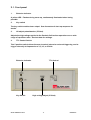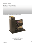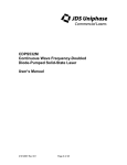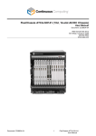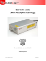
1
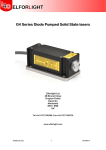
Spot Series Lasers
(Short Pulse Optical Technology)
Elforlight Ltd
4B Brunel Close
Drayton Fields
Daventry
Northants
NN11 8RB
UK
Tel +44 1327 300069: Fax +44 1327 300076
www.elforlight.com
SPOT V2I6 Manual.docx
1
08/08/2014
NOTICE
Elforlight Ltd. has made every attempt to ensure that the information in this document is
accurate and complete. Elforlight Ltd. assumes no liability for errors, or for any incidental,
consequential, indirect or special damages, including, without limitation, loss of use, delays or
lost profits or savings, arising from the use of this document, or the product which it
accompanies.
The contents of this manual are subject to change without notice. Please contact the factory to
ensure you have the latest revision of this document before embarking on critical design.
No part of this document may be reproduced or transmitted in any form or by means, electronic
or mechanical, for any purpose without written permission from Elforlight Ltd.
Elforlight Ltd. acknowledges the trademarks of other organizations for their respective
products or services mentioned in this document.
© 2012 Elforlight Ltd.
All rights reserved.
SPOT V2I6 Manual.docx
2
08/08/2014
Contents
1. Basic User Manual
1.1. System Description
1.2. Laser safety
1.3. Recommended safety precautions during laser operation
1.4. System handling, mounting and heat-sinking
1.5. Basic Operation
Connections
Start-up procedure
1.6. Operation with power variation
2. User Guide: SPOT Power Supply
2.1. Front Panel
2.2. Rear panel
2.3. RS232 commands
SPOT V2I6 Manual.docx
3
08/08/2014
1.1. System Description
The SPOT laser systems consist of a laser head with a separate power supply unit.
The power supply unit contains the drive circuits for the pump laser diode and the
temperature control of the laser system, as well as the DC supplies for these
modules and to supply the HV for the Pockels Cell. There is an interconnecting cable
from the laser head which is hard wired into the laser head while having a 37 way ‘D’
connector for connection to the power supply unit.
The power supply requires a mains input of 100-240 VAC, 50 or 60 Hz, capable of
providing up to 200VA.
SPOT lasers are designed to generate short pulses of laser output at 1064nm (and
harmonics if specified). The output power level will depend on the model but it
should be remembered that all SPOT lasers emit laser radiation which is potentially
hazardous and it is therefore strongly recommended that before operating the laser
for the first time users should thoroughly familiarise with the contents of this manual.
Of particular importance are the sections dealing with safe operation of the laser
and general safety issues.
Please refer to Section 2 for full details of power supply operation.
Q-switch voltage adjustment with repetition rate
With variation of repetition rate up to 50 kHz, it is necessary to adjust the high
voltage applied to the Q-switch to optimise output in terms of pulse width and
stability. This can be done by monitoring the output pulse on a photodiode and
oscilloscope whilst adjusting the voltage using the 10 turn potentiometer (if fitted) on
the front panel. Voltage values are given in the test data table above for various
repetition rates. The potentiometer (if fitted) can be locked by sliding the plastic
lever to the right, and unlocked by sliding it to the left.
SPOT V2I6 Manual.docx
4
08/08/2014
1.2. Laser Safety
This handbook contains a description of controls, adjustments and procedures for
normal operation of the laser. CAUTION - Use of controls or adjustments or
performance of procedures other than those specified herein may result in hazardous
radiation exposure.
Classification
Elforlight SPOT series lasers are classified as class 4 Lasers as defined by BS EN
60825-1:1994 and by the United States Centre for Device and Radiological Health
(CDRH) 21 CFR Ch. 1 subsection 1040. This designates potential danger of eye or skin
damage by exposure to direct or scattered radiation. It is recommended that all users
should thoroughly familiarise themselves with these safety standards before operating
the laser for the first time. It should be noted the all SPOT lasers are designed as OEM
sub-systems. As such they do not comply with all the requirements of BSEN 608251:1994 and CDRH 21 CFR Ch. 1 subsection1040. It is the user’s responsibility to ensure
full compliance with these standards.
Emission
The laser emits CW or pulsed radiation at 1064nm, 532nm and 355nm (or as otherwise
specified). Powers up to 2Watts may be generated. The laser head also contains a
laser diode emitting radiation at 808 nm within the head package. THE LASER HEAD
COVER MUST NOT BE REMOVED. No customer serviceable parts are contained
therein. Such access may invalidate any warranty offered by the manufacturer.
Indicators
An emission indicator on the front panel of the power supply indicates that laser
emission is possible.
External interlock
The SPOT series laser systems are provided with an external interlock facility which is
available on a Neutrik 3 way socket on the rear panel. This connector requires contact
closure to enable laser operation. The laser is supplied with a shorted connector, but
it is recommended that the short be replaced by a link into an external interlock
chain - e.g. a room door switch or enclosure cover switch. If the interlock is broken,
it is necessary to power down the laser at the keyswitch, then remake the interlock
connection and commence the start sequence again to resume laser output.
SPOT V2I6 Manual.docx
5
08/08/2014
1.3. Recommended Safety Precaution during Laser Operation
The laser should be used in an enclosed area with access restricted to trained
personnel. The area should be clearly labelled and the entrance marked with the class
of laser (Class 3B).
Only trained personnel should be allowed to use the laser.
The key must be inserted in the keyswitch and turned to enable the laser to operate.
The key is captive in the operational position. As such, the key should be removed
from the laser when not in use, and / or unattended, and stored in a safe place.
Eye and skin exposure to direct or scattered laser radiation is hazardous and should
be considered potentially extremely harmful.
Suitable eye protection should be worn at all times whilst laser output is possible.
Contact Elforlight for advice on suitable eye protection products.
The laser beam path should be terminated with a non-reflecting beam stop. Beam
paths should be enclosed where possible, and should not be at eye level if practical.
Care should be taken that all mirrors and optics used are securely positioned and fixed
to prevent movement. Care should be taken at all times to prevent stray reflections
from surfaces in the beam path.
SPOT V2I6 Manual.docx
6
08/08/2014
1.4. System Handling, Mounting and Heatsinking
It must be appreciated that any solid state laser system, especially the laser
head, is a sensitive piece of scientific equipment. Whilst every effort has been
made to provide a product that is rugged and reliable it is essential that the
laser head is handled with care – especially when mounting. Do not drop or
subject the head to impact shock such as placing it down hard on a surface.
ANY DAMAGE OR MALFUNCTION OF THE EQUIPMENT DUE TO EXCESSIVE
FORCE MAY INVALIDATE ANY WARRANTY.
1.5. Basic Operation
The SPOT series Diode Pumped Laser Systems are designed for simple, user-friendly
control with the minimum of user defined parameters. SPOT lasers are designed as
fixed power level devices under automatic operation, or power can be varied by
adjusting the pump diode current via RS232 interface. The power drawn from the AC
mains is less than 200 VA (typically approx. 50 VA). The laser head incorporates
laser diode protection circuitry and therefore the laser diode is protected even when
disconnected from the laser power supply. However, Elforlight recommend the
observance of full anti-static precautions during connection and disconnection of
the system sub-units. Please contact Elforlight for recommended anti-static
procedures.
Connect the laser head to the power supply unit using the 37 way ‘D’ connector
socket on the rear of the power supply. Be sure that the cable is kept away from the
laser beam path. Ensure the external interlock connector is in place in the socket
on the PSU rear panel. Ensure that the external interlock circuit is closed, either by
use of the supplied shorted connector (temporarily for test only), or via a usersupplied door or enclosure protection circuit. This interlock should be incorporated
into an area or enclosure interlock system. Please contact Elforlight for advice
regarding suitable interlock arrangements.
Either connect a user supplied TTL trigger signal to the Trigger BNC connector on
the laser head or connect a BNC cable from the PSU rear panel “trigger out” BNC
connector to the laser head “Trigger” BNC to run on the internal trigger. In the latter
case, select the desired operating frequency using the front panel switch: 1,5,10, or
25 kHz.
These values are approximate and provided for the convenience of the user. It is
anticipated that in most applications the SPOT laser will be externally triggered.
Connect the mains cable to the rear panel socket. Apply power, switch on the rear
panel rocker switch integral with the mains inlet, and turn the key switch to the ON
position.
SPOT V2I6 Manual.docx
7
08/08/2014
Operation:
The SPOT laser executes a start-up procedure during which the output power will vary.
During this sequence, the front panel LED emission indicator flashes at 0.5 Hz. Only
when the LED is on continuously is the laser stabilised and ready for use. Before this,
lower or higher powers may be observed from the laser. The SPOT laser exhibits two
different start-up sequences depending on the length of time the unit has been
connected to the mains supply. These may be described as:
1. ‘Cold start’ sequence.
2. ‘Warm start’ sequence.
1. The cold start sequence is activated when the system has been powered down
and is subsequently reconnected to the mains supply, that is, on initial start-up.
1.1 Connect power supply to mains supply and switch ON. Insert keyswitch and
turn ON.
The cold start sequence now begins with a thermal stabilisation period. From power
up this phase takes a total of 4 minutes. During this period no laser output will be
generated irrespective of whether the key-switch is in the ‘OFF’ (anticlockwise) or
‘ON’ (clockwise position). The keyswitch may be switched ‘ON’ at any time during
this 4 minute period without prolonging the next stage of start-up.
After the above 4 minute ‘warm up’ period, upon turning the key switch, or
immediately after the “warm up” period if the key has already been turned, the
supply switches automatically to a current ramp mode which varies with parameter
settings but should last no more than 2 minutes. During this period some laser light
may or may not be emitted depending on the individual set up parameters of the
laser.
After the above current ramp period the laser is put into a 2 minute stabilisation
mode. At the end of this period the Emission indicator will remain permanently on
and the laser is ready for use.
The warm start sequence is activated any time the key-switch is moved from the
‘OFF’ position to the ‘ON’ position provided the system has been powered up for at
least 4 minutes.
The warm start sequence activates the final two periods as in 1.1 above; that is the
‘ramp period’ and the ‘stabilisation’ period.
Once the laser is running, monitor the output pulse shape with a photodiode and
oscilloscope. The HV adjust (if fitted) potentiometer can then be fine-tuned for best
stability and minimum pulse width. This setting will vary with drive level and
repetition rate.
SPOT V2I6 Manual.docx
8
08/08/2014
NOTE (1) if the system is powered down even momentarily at any time, when the
system is powered up subsequently the system will automatically revert to the cold
start sequence.
NOTE (2) during the ‘ramp’ and ‘stabilisation’ operation phase the laser output
power will vary significantly from the specified output power. This behaviour is quite
normal as during this period optical stabilisation is occurring.
NOTE (3) breaking the interlock chain causes the laser to shut down. Once the
chain is remade, it is necessary to turn the key off then on to restart the laser. As
long as power has not been removed, this will then cause the laser to start in the
“warm start” sequence describes above.
1.6. Operation with power variation
Power variation is possible by RS 232 interface, with commands sent from a dumb
terminal.
The programs Terminal and/or HyperTerminal are provided with Windows software
and can be used. The program should be configured with the parameters listed
below.
9600 baud
1 start bit, 8 data bits, no parity and 1 stop bit
No hardware handshaking
No flow control
To operate the laser using power variation by RS 232 interface, first boot the
computer, run “Terminal”. Then connect the RS232 lead, and power up the laser as
described above. An introductory message appears confirming PSU SEEPROMs
detected (Head SEEPROM not detected is normal and not a fault), Digipots 1&2
detected, and listing SPOT software version e.g. V2I6. Turn the key.
A message “Warm up” confirms that a 4 minute warm up period is in progress,
followed by “Current Ramp” and “Stabilisation…Please Wait”, then after 2 minutes
“System Ready” confirms the laser is operating.
During this start-up phase, the emission LED flashes. Once ready, the emission LED
is on solid.
The “+” and “-” keys can then be used to increase and decrease the pump diode
current and hence laser power. The current is set by an 8 bit Digipot, with values 1
to 254 being accepted. At each key press, the value “xxx” is returned. Xxx is the
value between 1 and 254. See test data for calibration of values with current and
corresponding power output.
SPOT V2I6 Manual.docx
9
08/08/2014
2. SPOT Power Supply
The SPOT supply also contains:
An OEM 18-04 Controller
A triple rail DC supply for the above
A 5V DC supply for the high voltage switch in the HV module
A further adjustable DC supply to drive the high voltage supply in the HV module
A cooling fan
Interconnecting wiring to bring limited functionality of the 18-04 supply to the front
panel
The SPOT laser software is limited in functionality. It enables the user to vary laser
power by varying pump diode current, and to check the laser status.
SPOT V2I6 Manual.docx
10
08/08/2014
2.1. Front panel
1.
Emission indicator
A yellow LED. Flashes during warm up, continuously illuminated when lasing
possible.
2.
Key switch
The key switch enables laser output. See discussion of start-up sequence for
details.
3.
HV adjust potentiometer (if fitted).
Adjusts the high voltage applied to the Pockels Cell to allow operation over a wide
range of repetition rates. See test data for settings.
4.
TTL Control Switch
This 5 position switch allows the user to select internal or external triggering, and to
trigger internally at frequencies of 1,5,10, or 25 kHz.
Emission Indicator
Key Switch
SPOT V2I6 Manual.docx
TTL Control
High voltage adjust (if fitted)
11
08/08/2014
2.2. Rear panel
1.
Mains inlet
The mains inlet is a standard IEC connector. A suitable mains cable is usually supplied with
the laser, as appropriate to the local supply. The mains inlet is fused and switched. Fuse
rating is 5 Amps, slow blow (T).
2.
RS232 cable
Connects laser PSU to serial (COM) port of computer. Computer runs dumb terminal
program such as Terminal or Hyperterminal. PSU end is a round 5 way DIN connector.
3.
External Interlock connector
A 3 way Neutrik connector. Contact closure between pins 1 and 3 is required to enable laser
operation. Laser is supplied with a connector with a shorting link in place.
4.
Laser head 37 way D-connector:
Provides laser diode drive current, temperature control and monitoring of laser functions.
THIS CONNECTOR SHOULD NEVER BE CONNECTED OR DISCONNECTED WHILST THE
LASER SYSTEM IS POWERED UP.
5.
Safety fuse for laser head
Carries +5V supply to laser head. Fuse rating is 1.25A, slow blow (T).
6.
Trigger out connector
This BNC connector provides TTL trigger output to be taken to the laser head Trigger BNC
for internal triggering at the frequency selected by the front panel switch.
5
1
SPOT V2I6 Manual.docx
6
4
12
2
3
08/08/2014
2.3. SPOT Laser RS232 Commands
Allows User to change laser diode current (Iset), and thus laser power
+
Increment Iset parameter by one
-
Decrement Iset parameter by one
?
Request status
Q
Request software version number
RS232 protocol:
9600 baud
1 start bit, 8 data bits, no parity, 1 stop bit
No hardware handshaking
No software handshaking
RS232 Cable wiring:
PC End
Laser End
9 way
9 way
D type
D type
Socket
Plug
1
2
------------------- 2
3
------------------- 3
4
5
------------------- 5
4-6
7-8
SPOT V2I6 Manual.docx
13
08/08/2014