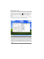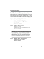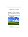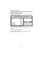
1
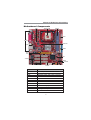
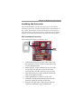
Motherboard User’s Guide This publication, including photographs, illustrations and software, is under the protection of international copyright laws, with all rights reserved. Neither this manual, nor any of the material contained herein, may be reproduced without the express written consent of the manufacturer. The information in this document is subject to change without notice. The manufacturer makes no representations or warranties with respect to the contents hereof and specifically disclaims any implied warranties of merchantability or fitness for any particular purpose. Further, the manufacturer reserves the right to revise this publication and to make changes from time to time in the content hereof without obligation of the manufacturer to notify any person of such revision or changes. Trademarks IBM, VGA, and PS/2 are registered trademarks of International Business Machines. Intel, Pentium/II/III, Pentium 4, Celeron and MMX are registered trademarks of Intel Corporation. Microsoft, MS-DOS and Windows 98/ME/NT/2000/XP are registered trademarks of Microsoft Corporation. PC-cillin is a trademark of Trend Micro Inc. AMI is a trademark of American Megatrends Inc. It has been acknowledged that other brands or product names in this manual are trademarks or the properties of their respective owners. Copyright © 2004 All Rights Reserved PI845GVM-AGP/PI845GLM-AGP V1.0 I845/August 2004 i Motherboard User’s Guide Table of Contents Trademark ................................................................................... I Static Electricity Precautions ............................................................ III Pre-Installation Inspection ................................................................ III Chapter 1: Introduction ............................................................ 1 Key Features ........................................................................................ 2 Package Contents ................................................................................ 5 Chapter 2: Motherboard Installation ..................................... 6 Motherboard Components ................................................................... 7 I/O Ports ............................................................................................... 8 Installing the Processor ....................................................................... 9 Installing Memory Modules ............................................................... 10 Jumper Settings .................................................................................. 12 Install the Motherboard ..................................................................... 13 Connecting Optional Devices ............................................................ 14 Install Other Devices .......................................................................... 17 Expansion Slots .................................................................................. 21 VGA Card Support List for AGP Ultra Slot.............................................21 Dual Monitor ...............................................................................................23 Chapter 3: BIOS Setup Utility ............................................... 29 Introduction ....................................................................................... 29 Running the Setup Utility ................................................................. .24 Standard CMOS Setup Page ............................................................. 31 Advanced Setup Page ........................................................................ 32 Power Management Setup Page ........................................................ 35 PCI/Plug and Play Setup Page .......................................................... 37 Load Optimal Settings ...................................................................... 38 Load Best Performance Settings ........................................................ 38 Features Setup Page .......................................................................... 39 CPU PnP Setup Page ......................................................................... 41 Hardware Monitor Page .................................................................... 42 Change Password and Exit ................................................................ 43 Chapter 4: Software & Applications ..................................... 44 Introduction ....................................................................................... 44 Installing Support Software ............................................................... 45 Bundled Software Installation ........................................................... 47 Hyper-Threading CPU ....................................................................... 48 ii Motherboard User’s Guide Static Electricity Precautions Static electricity could damage components on this motherboard. Take the following precautions while unpacking this motherboard and installing it in a system. 1. Don’t take this motherboard and components out of their original static-proof package until you are ready to install them. 2. While installing, please wear a grounded wrist strap if possible. If you don’t have a wrist strap, discharge static electricity by touching the bare metal of the system chassis. 3. Carefully hold this motherboard by its edges. Do not touch those components unless it is absolutely necessary. Put this motherboard on the top of static-protection package with component side facing up while installing. Pre-Installation Inspection 1. Inspect this motherboard whether there are any damages to components and connectors on the board. 2. If you suspect this motherboard has been damaged, do not connect power to the system. Contact your motherboard vendor about those damages. iii Motherboard User’s Guide Notice: Owing to Microsoft’s certifying schedule is various to every supplier, we might have some drivers not certified yet by Microsoft. Therefore, it might happen under Windows XP that a dialogue box (shown as below) pop out warning you this software has not passed Windows Logo testing to verify its compatibility with Windows XP. Please rest assured that our RD department has already tested and verified these drivers. Just click the “Continue Anyway” button and go ahead the installation. iv Chapter 1: Introduction Chapter 1 Introduction This motherboard has a Socket-478 supporting Intel Pentium 4/ Prescott with Hyper-Threading Technology processors with Front-Side Bus (FSB) speeds up to 533/400 MHz. HyperThreading Technology, designed to take advantage of the multitasking features in Windows XP, gives you the power to do more things at once. Note: It supports Hyper-Threading Technology only when the Intel 845GV is installed. Intel 845GL supports FSB 533 MHz only by overclocking. This motherboard has the Intel 845GL/GV chipset that contains Intel 82845 Memory Controller Hub and Intel 82801 I/O Controller Hub. It supports built-in USB 2.0 providing higher bandwidth. It implements Universal Serial Bus Specification Revision 2.0 and includes three UHCI host controllers that support six external ports. This motherboard supports AC’ 97 audio codec and provides Ultra DMA 100/66/33/ function. This motherboard has one CNR (Communications and Networking Riser), three 32-bit PCI slots and one AGP Ultra slot. There is a full set of I/O ports including two PS/2 ports for mouse and keyboard and audio jacks for microphone, line-in and line-out. There are one serial port, one VGA port, one parallel port, one LAN port(optional), and six USB ports (USB2.0)–four back-panel ports and onboard USB header USB3 providing two extra ports by connecting the Extended USB Module to the motherboard. This motherboard is a Micro ATX motherboard that uses a 4layer printed circuit board and measures 244 x 220mm. 1 Motherboard User’s Guide Note: You must initiate the HT CPU function through BIOS setup. It is strongly recommended you refer to Page 48 for related details. Key Features The key features of this motherboard include: Socket-478 Processor Supports Intel Pentium 4 series CPU with/without Hyper-Threading Technology Supports up to 533/400 MHz Front-Side Bus Chipset There are Intel 845GV/GL chipsets that contain Intel 82845 Memory Controller Hub and Intel 82801DB I/O Controller Hub(ICH4) in accordance with an innovative and scalable architecture with proven reliability and performance. Here is a list of the chipset arrangement and their respective features: Northbridge 845GV 845GL Function Support: CPU FSB: 533/400MHz Hyper-Threading Technology DDR333/266; USB2.0; Ultra ATA 100/66/33 Support: CPU FSB: 533*/400MHz DDR266; USB 2.0; Ultra ATA 100/66/33 Doesn’t support:Hyper-Threading Technology * Supports FSB 533 MHz only by over-clocking Memory Support Two 184-pin DIMM sockets for DDR SDRAM memory modules 2 Chapter 1: Introduction Support DDR up to 333MHz (845GV) or DDR266MHz (845GL) memory bus Maximum installed memory is 2GB AC’97 Codec Compliant with AC’97 2.3 specification Full-duplex Codec with independent and variable sampling rate Earphone Buffer Built-In, SNR up to 90db 6Ch DAC, support 6-channel speak-out Advanced power management support Expansion Options One AGP Ultra slot (refer to page 21 for more details) Three 32-bit PCI slots One CNR (Communications and Networking Riser) slot Support IDE Ultra DMA bus mastering with transfer rates of 100/66/33 MB/sec Onboard I/O Ports The motherboard has a full set of I/O ports and connectors: Two PS/2 ports for mouse and keyboard One serial port One VGA port One LAN port (optional) One parallel port Four back-panel USB 2.0 ports Audio jacks for microphone, line-in and line-out Fast Ethernet LAN (optional) 10 Mb/s and 100 Mb/s operation Integrated Fast Ethernet MAC PCI local bus single-chip Fast Ethernet controller -Compliant to PCI Revision 2.2 -Supports ACPI, PCI power management Compliant to PC99/PC2001 standard 3 Motherboard User’s Guide Supports a 32-bit general-purpose timer with the external PCI clock as clock source, to generate timer-interrupt Supports Full Duplex Flow Control (IEEE 802.3x) USB 2.0 Includes three UHCI host controllers that support six external ports New: Includes one EHCI high-speed USB 2.0 Host Controller that supports all six ports New: Supports a USB 2.0 high-speed debug port Supports wake-up from sleeping states S1-S5 Supports legacy keyboard/mouse software BIOS Firmware This motherboard uses AMI BIOS that enables users to configure many system features including the following: Power management Wake-up alarms CPU parameters and memory timing CPU and memory timing The firmware can also be used to set parameters for different processor clock speeds. Bundled Software PC-Cillin provides automatic virus protection under Windows 98/ME/NT/2000/XP Adobe Acrobat Reader is the software to help users read PDF files. Dimensions Micro ATX form factor of 244 x 220mm Note: Hardware specifications and software items are subject to change without notification. 4 Chapter 1: Introduction Package Contents Your motherboard package contains the following items: The motherboard The User’s Manual One diskette drive ribbon cable(optional) One IDE drive ribbon cable Software support CD Optional Accessories You can purchase the following optional accessories for this motherboard. Extended USB module CNR v.90 56K Fax/Modem card Card Reader (You can buy your own Card Reader from the third party, but please contact your local Card Reader vendor on any issues of the specification and compatibility.) 5 Motherboard User’s Guide Chapter 2 Motherboard Installation To install this motherboard in a system, please follow these instructions in this chapter: • • • • • • Identify the motherboard components Install a CPU Install one or more system memory modules Make sure all jumpers and switches are set correctly Install this motherboard in a system chassis (case) Connect any extension brackets or cables to headers/ connectors on the motherboard • Install peripheral devices and make the appropriate connections to headers/connectors on the motherboard Note: 1. Before installing this motherboard, make sure jumper JP2 is under Normal setting. See this chapter for information about locating JP2 and the setting options. 2. Never connect power to the system during installation; otherwise, it may damage the motherboard. 3. Refer to page 21 first to install the AGP graphics card on the AGP Ultra slot. 6 Chapter 2: Motherboard Installation Motherboard Components ATX1 Socket-478 DDR1/2 PW1 IO PORTS CPU FAN READ1 IDE2/1 AGP1 SIR1 JP2 AUDIO2 PLED1 CHS FAN CD1 LABEL DDR1-2 IDE1/2 ATX1 PW1 USB3 FLOPPY PANEL1 CHS FAN JP2 SPKR1 CD1 PLED1 CN R1 PCI1-3 FLOPPY USB3 SPKR1 PANEL1 COMPONENTS Two 184-pin DDR SDRAM sockets Primary/Secondary IDE connectors Standard 4-Pin ATX Power connector Standard 20-Pin ATX Power connector Front Panel USB header Floppy Disk Drive connector Front Panel Switch/LED header System Fan connector Clear CMOS jumper Speaker header Analog Audio Input header Power-On indicator header 7 Motherboard User’s Guide LABEL SIR1 PCI 1-3 AUDIO2 CPUFAN CNR1 AGP1 READ1 COMPONENTS Infrared Port header 32-bit PCI slots Front Panel Audio header CPU Fan connector Communications Networking Riser slot AGP Ultra slot *See page 21 for details Card Reader Header I/O Ports The illustration below shows a side view of the built-in I/O ports on the motherboard. Shared with READ1 PS/2 Mouse (Optional) Use the upper PS/2 port to connect a PS/2 pointing device. PS/2 Keyboard Use the lower PS/2 port to connect a PS/2 keyboard. Parallel Port (LPT1) Use the Parallel port to connect printers or other parallel communications devices. Use the COM port to connect serial devices Serial Port COM1 such as mice or fax/modems. COM1 is identified by the system as COM1. Use the VGA port to connect VGA devices. VGA Port LAN Port (optional) Connect an RJ-45 jack to the LAN port to connect your computer to the Network. Use the USB ports to connect USB devices. USB Ports Note: The lower USB port located beside the VGA port is shared with the READ1 header. Use the three audio ports to connect audio Audio Ports devices. The first jack is for stereo Line-In signal. The second jack is for stereo Line-Out signal. The third jack is for Microphone. 8 Chapter 2: Motherboard Installation Installing the Processor This motherboard has a Socket 478 processor socket. When choosing a processor, consider the performance requirements of the system. Performance is based on the processor design, the clock speed and system bus frequency of the processor, and the quantity of internal cache memory and external cache memory. CPU Installation Procedure Follow these instructions to install the CPU: pin1 1 CPUFAN Socket-478 1. Unhook the locking lever of the CPU socket. Pull the locking lever away from the socket and raising it to the upright position. 2. Match the pin1 corner marked as the beveled edge on the CPU with the pin1 corner on the socket. Insert the CPU into the socket. Do not use force. 3. Push the locking lever down and hook it under the latch on the edge of socket. 4. Apply thermal grease to the top of the CPU. 5. Install the cooling fan/heatsink unit onto the CPU, and secure them all onto the socket base. 6. Plug the CPU fan power cable into the CPU fan connector (CPUFAN) on the motherboard. 9 Motherboard User’s Guide Installing Memory Modules This motherboard accommodates two 184-pin 2.5V unbuffered Double Data Rate SDRAM (DDR SDRAM) Dual Inline Memory Module (DIMM) sockets, and supports up to 2.0 GB of 333(845GV)/266/200 MHz DDR SDRAM. DDR SDRAM is a type of SDRAM that supports data transfers on both edges of each clock cycle (the rising and falling edges), effectively doubling the memory chip’s data throughput. DDR1 DDR2 10 Chapter 2: Motherboard Installation Memory Module Installation Procedure These modules can be installed with up to 2 GB system memory. Refer to the following to install the memory module. 1. 2. Push down the latches on both sides of the DIMM socket. Align the memory module with the socket. There is a notch on the DIMM socket that you can install the DIMM module in the correct direction. Match the cutout on the DIMM module with the notch on the DIMM socket. 3. Install the DIMM module into the socket and press it firmly down until it is seated correctly. The socket latches are levered upwards and latch on to the edges of the DIMM. 4. Install any remaining DIMM modules. 11 Motherboard User’s Guide Jumper Settings Connecting two pins with a jumper cap is SHORT; removing a jumper cap from these pins, OPEN. 1 JP2 JP2: Clear CMOS Jumper Use this jumper to clear the contents of the CMOS memory. You may need to clear the CMOS memory if the settings in the Setup Utility are incorrect and prevent your motherboard from operating. To clear the CMOS memory, disconnect all the power cables from the motherboard and then move the jumper cap into the CLEAR setting for a few seconds. Function Jumper Setting Normal Short Pins 1-2 Clear CMOS Short Pins 2-3 12 Chapter 2: Motherboard Installation Install the Motherboard Install the motherboard in a system chassis (case). The board is a Micro-ATX size motherboard. You can install this motherboard in an ATX case. Make sure your case has an I/O cover plate matching the ports on this motherboard. Install the motherboard in a case. Follow the case manufacturer’s instructions to use the hardware and internal mounting points on the chassis. 1 ATX1 PW1 CHS FAN 1 PANEL1 Connect the power connector from the power supply to the PW1 connector on the motherboard. The ATX1 is a +12V connector for CPU Vcore power. If there is a cooling fan installed in the system chassis, connect the cable from the cooling fan to the CHS FAN fan power connector on the motherboard. Connect the case switches and indicator LEDs to the PANEL1 header. Please refer to the following list of the PANEL1 pin assignments. 13 Motherboard User’s Guide Pin Signal 1 HD_LED_P(+) 3 HD_LED_N(-) 5 RESET_SW_N(-) 7 RESET_SW_P(+) 9 RSVD_DNU Pin Signal 2 FP PWR/SLP(+) 4 FP PWR/SLP(-) 6 POWER_SW_P(+) 8 POWER_SW_N(-) 10 KEY Connecting Optional Devices Refer to the following for information on connecting the motherboard’s optional devices: 1 READ1 SIR1 1 1 PLED1 1 1 AUDIO2 SPKR1 1 USB3 SPKR1: Speaker Header Connect the cable from the PC speaker to the SPKR1 header on the motherboard. Pin Signal Pin Signal 1 SPKR 2 NC 3 GND 4 +5V 14 Chapter 2: Motherboard Installation AUDIO2: Front Panel Audio Header This header allows the user to install auxiliary front-oriented microphone and line-out ports for easier access. Pin Signal Pin Signal 1 AUD_MIC 2 AUD_GND 3 AUD_MIC_BIAS 4 AUD_VCC 5 AUD_FPOUT_R 6 AUD_RET_R 7 HP_ON 8 KEY 9 AUD_FPOUT_L 10 AUD_RET_L USB3: Front Panel USB Header The motherboard has USB ports installed on the rear edge I/O port array. Additionally, some computer cases have USB ports at the front of the case. If you have this kind of case, use auxiliary USB header USB3 to connect the front-mounted ports to the motherboard. Pin Signal 1 VERG_FP_USBPWR0 3 USB_FP_P0(-) 5 USB_FP_P0(+) 7 GROUND 9 KEY 1. 2. 3. Pin 2 4 6 8 10 Signal VERG_FP_USBPWR0 USB_FP_P1(-) USB_FP_P1(+) GROUND USB_FP_OC0 Locate the USB3 header on the motherboard. Plug the bracket cable onto the USB3 header. Remove a slot cover from one of the expansion slots on the system chassis. Install an extension bracket in the opening. Secure the extension bracket to the chassis with a screw. 15 Motherboard User’s Guide READ1: USB Card Reader Header (optional) This header is for connecting internal USB card reader. You can use a card reader to read or transfer files and digital images to your computer. Pin Signal Pin Signal 1 Vcc 2 USB3 USB+ 4 GND 5 KEY Note: The READ1 is shared with one of the USB ports of the I/O back panel. The USB port is located beside the VGA port connector. See “I/O Ports” for information. Note: Please check the pin assignment of the cable and the USB header on the motherboard. Make sure the pin assignment will match before plugging in. Any incorrect usage may cause unexpected damage to hte system. The vendor won’t be responsible for any incidental or consequential damage arising from the usage or misusage of the purchased product. PLED1: Power-On Indicator Header If there is another power-on indicator LED installed in the system chassis, connect the LED to the PLED1 header. Pin 1 2 3 Signal GROUND NC POWER 16 Chapter 2: Motherboard Installation SIR1: Infrared Header The infrared port allows the wireless exchange of information between your computer and similarly equipped devices such as printers, laptops, Personal Digital Assistants (PDAs), and other computers. Pin Signal 1 NC 3 +5V 5 IRTX 1. 2. Pin 2 4 6 Signal KEY GND IRRX Locate the infrared port-SIR1 header on the motherboard. If you are adding an infrared port, connect the ribbon cable from the port to the SIR1 header and then secure the port to an appropriate place in your system chassis. Install Other Devices Install and connect any other devices in the system following the steps below. IDE2 IDE1 1 FLOPPY 1 17 1 Motherboard User’s Guide Floppy Disk Drive The motherboard ships with a floppy disk drive cable that can support one or two drives. Drives can be 3.5" or 5.25" wide, with capacities of 360K, 720K, 1.2MB, 1.44MB, or 2.88MB. Install your drives and connect power from the system power supply. Use the cable provided to connect the drives to the floppy disk drive connector FLOPPY. IDE Devices IDE devices include hard disk drives, high-density diskette drives, and CD-ROM or DVD-ROM drives, among others. The motherboard ships with an IDE cable that can support one or two IDE devices. If you connect two devices to a single cable, you must configure one of the drives as Master and one of the drives as Slave. The documentation of the IDE device will tell you how to configure the device as a Master or Slave device. The Master device connects to the end of the cable. Install the device(s) and connect power from the system power supply. Use the cable provided to connect the device(s) to the Primary IDE channel connector IDE1 on the motherboard. If you want to install more IDE devices, you can purchase a second IDE cable and connect one or two devices to the Secondary IDE channel connector IDE2 on the motherboard. If you have two devices on the cable, one must be Master and one must be Slave. 18 Chapter 2: Motherboard Installation Analog Audio Input Header If you have installed a CD-ROM drive or DVD-ROM drive, you can connect the drive audio cable to the onboard sound system. 1 CD1 When you first start up your system, the BIOS should automatically detect your CD-ROM/DVD drive. If it doesn’t, enter the Setup Utility and configure the CD-ROM/DVD drive that you have installed. On the motherboard, locate the 4-pin header CD1. Pin 1 2 3 4 Signal CD IN L GND GND CD IN R 19 Motherboard User’s Guide Expansion Slots This motherboard has one AGP Ultra, one CNR and three 32-bit PCI slots. AGP1 PCI1 PCI2 PCI3 CNR1 Follow the steps below to install a CNR/PCI expansion card. 1. Locate the CNR or PCI slots on the motherboard. 2. Remove the slot cover for this slot from the system chassis. 3. Insert the expansion card edge connector into the slot and press it firmly down into it so that it is fully inserted. 4. Secure the expansion card bracket to the system chassis with a screw. AGP Ultra Slot (AGP1) The AGP Ultra slot is used to install AGP graphics card that emulates the AGP function. In order to get better performance and compatibility on our special design AGP Ultra slot, we recommend users use one of the AGP graphics cards that have been tested by our company. Please refer to page 21 for the “VGA Card Support List for AGP Ultra Slot”. Note: If the AGP card is already installed, the computer won’t auto setup the onbaord VGA driver. 20 Chapter 2: Motherboard Installation VGA Card Support List for AGP Ultra Slot: VGA Chipset Manufacture ATI Radeon 7000 ATI Radeon 8500 ATI Radeon 9000 PRO ATI Radeon 9200 8X ATI Radeon 9800 XT 8X RIVA TNT2 TNT2 M64 GeForce 256 GeForce 256 DDR GeForce 2 GTS GeForce 2 GTS DDR PRO GeForce 2 MX GeForce 2 MX GeForce 2 MX GeForce 2 Ultra DDR GeForce 2 MX200 GeForce 2 MX400 GeForce 3 DDR GeForce 3 Deluxe GeForce 3 Ti500 Deluxe GeForce 4 MX420 GeForce 4 MX440 GeForce 4 Ti4400 GeForce 4 Ti4600 8X GeForce 4 Ti4200 GeForce 4 MX440 8X GeForce 4 MX4000 8X GeForce FX5600 8X GeForce FX5900 ultra 8X GeForce FX5950 ultra 8X 8X Xabre 200 V1.0 8X Xabre 200 V1.1 Xabre 400 8X Xabre 400 V1.1 8X ECS ATI RADEON 8500 DDR Gigabyte GV-R9000 PRO ECS ELSA 980XT WINFAST 3DS320 Win Fast S325 Creative CT6940 ASUS V6800 Gigabyte ELSA GLADIAC ASUS AGP-V7100 ELSA Gladiac MX Triplex Mohock WINFAST Triplex-MX2200 ELSA GLADIAC 511 ELSA GLADIAC 920 ASUS V8200 ASUS V8200 WINFAST A170TH SDR ASUS V8170DDR ELSA 725DVI ELSA 925ViVo ASUS V9280TD/8X ASUS V9180VS/8X WinFast A180B ELSA FX 732 256MB MSI FX5900Ultra 256MB ELSA FX938Ultra 256MB ECS AG200E4-D32 ECS AG200T8-D64 ECS AG400T8-D64 ECS AG400T8-D64 Note: For the latest supported AGP graphics list, please visit our website: Http://www.kobian.com 21 Motherboard User’s Guide Once the AGP card is completely installed under Windows 2000 or Windows XP, the sign like this “? Video Controller” will pop up below the “Device Manager” as the following picture shows. It is normal to see the sign as the onboard VGA card is “Disabled”. Therefore, users don’t have to worry about this point. Note: To install the system with an add-on AGP card, you must make sure to install the driver of add-on AGP card before you install the onboard VGA driver. If the onboard VGA driver has already been installed before you install the add-on AGP card, the system will set the onboard VGA as the primary graphics adapter automatically. In this situation, if you want to install the add-on AGP card, you need to remove the onboard VGA driver first, and then install the add-on AGP card and its driver. 22 Chapter 2: Motherboard Installation PCI Slot You can install the 32-bit PCI interface expansion cards in the slots. CNR Slot This slot is used to insert CNR (Communications and Networking Riser) cards including LAN, Modem, and Audio functions. Dual Monitor In order to enable “Dual Monitor” Function, users must have “Two Monitors”, “Two Graphics Devices” (one is for AGP graphics card; the other one is for onboard VGA) and Windows 2000 or Windows XP that supports the Dual Monitor Function. Users must follow the “Dual Monitor Installation” below or visit our website at “Http://www.kobian.com” for detailed information. 23 Motherboard User’s Guide Dual Monitor Installation (For Windows XP) If the onboard VGA is first installed, and you would like to use the add-on AGP card. Please follow the installation steps 1-6. Users may go to step 4 directly if the add-on AGP card is installed first and then turned on the onboard VGA devices for “secondary display”. Step 1: Remove the Onboard VGA Driver Go to “Control Panel” Choose “Add or Remove Programs” Choose “IntelR Extreme Graphics Driver” Click “Remove” Shut down the computer Step 2: Install the Add-on AGP Card Shut down the system Install the add-on AGP card in the AGP Ultra slot Turn on the computer Note: When you turn on the system, windows might report Found New Hardware Wizard, “Video Controller(VGA Compatible)” or “Video Controller”. When you see the Found New Hardware Wizard dialogue box, DO NOT insert any disk in your CD/DVDROM before clicking on the “Next” button. The Windows Autosearch will not be finished till it can’t search the related driver. Step 3: Install the Add-on AGP Card Driver Install the add-on AGP card driver Restart the computer 24 Chapter 2: Motherboard Installation Step 4: Install the Onboard VGA Driver Install the onboard VGA driver from our suppport CD to utilize Dual Function. Here is the Driver Path: CD-ROM:\VGA\Intel845g\WIN2K&XP\Graphics\Setup.exe Restart the computer. Note: If the add-on AGP VGA card driver and onboard VGA drivers are installed, the dual-monitor display will be enabled. As soon as it is enabled, follow the instructions to view the status of the dual-monitor display or adjust the parameters of the two monitors. Step 5: Right click the desktop. Select “Properties” See the picture below. Step 6: Select “Display Properties” Click “Settings” Then the parameters of the two monitors can be adjusted. 25 Motherboard User’s Guide Dual Monitor Installation (For Windows 2000) If the onboard VGA is first installed, and you would like to use the add-on AGP card. Please follow the installation steps 1-6. Users may go to step 4 directly if the add-on AGP card is installed first and then turned on the onboard VGA devices for “secondary display”. Step 1: Install the Add-on AGP Card Shut down the system Install your add-on AGP card in the AGP Ultra slot Turn on the computer Step 2: Install the Add-on AGP Card Driver Install the add-on AGP card driver Restart the computer Note: Windows might report Found New Hardware Wizard once the system is turned on. When you see the “dialogue box” of the Found New Hardware Wizard, please click on “Cancel” and DO NOT install the onboard VGA driver. Step 3: Remove the Onboard VGA Driver Go to “Control Panel” Choose “Add or Remove Programs” Choose “Intel R Extreme Graphics Driver” Click “Remove” and Restart the computer Note: When you turn on the system, windows might report Found New Hardware Wizard, “Video Controller(VGA Compatible)” or “Video Controller”. When you see the Found New Hardware Wizard dialogue box, DO NOT insert any disk in your CD/DVD-ROM before clicking on the “Next” button. The Windows Auto-search will not be finished till it can’t search the related driver. 26 Chapter 2: Motherboard Installation Step 4: Install the Onboard VGA Driver Install the onboard VGA driver from our support CD to utilize Dual Monitor Function. Here is the Driver Path. CD-ROM:\VGA\Intel845g\WIN2K&XP\Graphics\Setup.exe Restart the computer. Note: If the add-on AGP VGA card driver and onboard VGA drivers are installed, the dual-monitor display will be enabled. As soon as it is enabled, follow the instructions to view the status of the dual-monitor display or adjust the parameters of the two monitors. Step 5: Right click the desktop. Select “Properties” See the picture below. Step 6: Select “Display Properties” Click “Settings” Then the parameters of the two monitors can be adjusted. 27 Motherboard User’s Guide MEMO 28 Chapter 3: BIOS Setup Utility Chapter 3 BIOS Setup Utility Introduction The BIOS Setup Utility records settings and information of your computer, such as date and time, the type of hardware installed, and various configuration settings. Your computer applies the information to initialize all the components when booting up and basic functions of coordination between system components. If the Setup Utility configuration is incorrect, it may cause the system to malfunction. It can even stop your computer booting properly. If it happens, you can use the clear CMOS jumper to clear the CMOS memory which has stored the configuration information; or you can hold down the Page Up key while rebooting your computer. Holding down the Page Up key also clears the setup information. You can run the setup utility and manually change the configuration. You might need to do this to configure some hardware installed in or connected to the motherboard, such as the CPU, system memory, disk drives, etc. 29 Motherboard User’s Guide Running the Setup Utility Every time you start your computer, a message appears on the screen before the operating system loading that prompts you to “Hit <DEL>if you want to run SETUP”. Whenever you see this message, press the Delete key, and the Main menu page of the Setup Utility appears on your monitor. AMIBIOS SIMPLE SETUP UTILITY –VERSION 1.21.12 (C) 2000 American Megatrends, Inc. All Rights Reserved Standard CMOS Setup Advanced Setup Power Management Setup PCI / Plug and Play Setup Load Optimal Settings Load Best Performance Settings Features Setup CPU PnP Setup Hardware Monitor Change Password Exit Esc:Quit :Select Item (Shift) F2: Change Color F5: Old Values F6: Optimal Values F7: Best Performance Values F10: Save&Exit Standard COMOS setup for changing time, date, hard disk type, etc. You can use cursor arrow keys to highlight anyone of options on the main menu page. Press Enter to select the highlighted option. Press the Escape key to leave the setup utility. Press +/-/ to modify the selected field’s values. Some options on the main menu page lead to tables of items with installed values that you can use cursor arrow keys to highlight one item, and press PgUp and PgDn keys to cycle through alternative values of that item. The other options on the main menu page lead to dialog boxes requiring your answer Yes or No by hitting the Y or N keys. If you have already changed the setup utility, press F10 to save those changes and exit the utility. Press F1 to display a screen describing all key functions. Press F6 to install the setup utility with a set of default values. Press F7 to install the setup utility with a set of high-performance values. 30 Chapter 3: BIOS Setup Utility Standard CMOS Setup Page This page displays a table of items defining basic information about your system. AMIBIOS SETUP – STANDARD CMOS SETUP (C) 2000 American Megatrends, Inc. All Rights Reserved Date (mm/dd/yyyy) : Tue Jun 08, 2004 Time (hh/mm/ss) : 12:41:42 LBA Blk PIO Type Size Cyln Head WPcom Sec Mode Mode Mode Pri Master : Auto Pri Slave : Auto Sec Master : Auto Sec Slave : Auto 32Bit Mode On On On On Floppy Drive A: 1.44 MB 31/2 Floppy Drive B: Not Installed Month : Jan – Dec Day : 01 – 31 Year : 1980 – 2099 ESC : Exit : Select Item PU/PD/+/- : Modify (Shift)F2 : Color F3 : Detect All HDD Date & Time These items set up system date and time. IDE Pri Master/Pri Slave/Sec Master/Sec Slave Use these items to configure devices connected to the Primary and Secondary IDE channels. To configure an IDE hard disk drive, choose Auto. If the Auto setting fails to find a hard disk drive, set it to User, and then fill in the hard disk characteristics (Size, Cyls, etc.) manually. If you have a CD-ROM drive, select the setting CDROM. If you have an ATAPI device with removable media (e.g. a ZIP drive or an LS-120), select Floptical. Floppy Drive A/B These items set up size and capacity of the floppy diskette drive(s) installed in the system. 31 Motherboard User’s Guide Advanced Setup Page This page sets up more advanced information about your system. Handle this page with caution. Any changes can affect the operation of your computer. AMIBIOS SETUP – ADVANCED SETUP (C) 2000 American Megatrends, Inc. All Rights Reserved 2.6V Memory Voltage Control Quick Boot Enabled IDE-0 1 st Boot Device 2 nd Boot Device Floppy 3 rd Boot Device CD/DVD-0 Try Other Boot Devices Yes S.M.A.R.T. for Hard Disks Disabled Floppy Drive Swap Disabled Floppy Drive Seek Disabled Password Check Setup L2 Cache Enabled System BIOS Cacheable Enabled SDRAM Frequency Auto SDRAM Timing by SPD Enabled 2.5 Clocks SDRAM CAS# Latency 3 Clocks SDRAM RAS# Precharge ESC:Quit :Select Item SDRAM RAS# to CAS# Delay 3 Clocks F1:Help PU/PD/+/-:Modify 7 Clocks SDRAM Precharge Delay F5:Old Values (Shift)F2:Color Hyper Threading Function Disabled F6:Load Optimal Values Spread Spectrum Disabled F7:Load Best Performance Values Auto Detect DIMM/PCI CLK Enabled Quick Boot If you enable this item, the system starts up more quickly be elimination some of the power on test routines. 1st Boot Device/2 nd Boot Device/3rd Boot Device Use these items to determine the device order the computer uses to look for an operating system to load at start-up time. Try Other Boot Device If you enable this item, the system will also search for other boot devices if it fails to find an operating system from the first two locations. 32 Chapter 3: BIOS Setup Utility S.M.A.R.T. for Hard Disks Enable this item if any IDE hard disks support the S.M.A.R.T. (Self-Monitoring, Analysis and Reporting Technology) feature. Floppy Drive Swap If you have two diskette drives installed and you enable this item, drive A becomes drive B and drive B becomes drive A. Floppy Drive Seek If you enable this item, your system will check all floppy disk drives at start up. Disable this item unless you are using an old 360KB drive. Password Check If you have entered a password for the system, use this item to determine, if the password is required to enter the Setup Utility (Setup) or required both at start-up and to enter the Setup Utility (Always). L2 Cache Leave these items enabled since all the processors that can be installed on this board have internal L2 cache memory. System BIOS Cacheable If you enable this item, a segment of the system BIOS will be copied to main memory for faster execution. SDRAM Frequency This item determines frequency of SDRAM memory. SDRAM Timing By SPD This item allows you to enable or disable the SDRAM timing defined by the Serial Presence Detect electrical. 33 Motherboard User’s Guide SDRAM CAS # Latency This item determins the operation of SDRAM memory CAS (column address strobe.) It is recommended that you leave this item at the default value. The 2T setting requires faster memory that specifically supports this mode. SDRAM RAS# Precharge Select the number of CPU clocks allocated for the Row Address Strobe (RAS#) signal to accumulate its charge before the SDRAM is refreshed. If insufficient time is allowed, refresh may be incomplete and data lost. SDRAM RAS# to CAS# Delay This field lets you insert a timing delay between the CAS and RAS strobe signals, used when SDRAM is written to, read from, or refreshed. Disabled gives faster performance; and Enabled gives more stable performance. SDRAM Precharge Delay The precharge time is the number of cycles it takes for SDRAM to accumulate its charge before refresh. Hyper Threading Function If your P4 CPU is not HT CPU, this item will be hidden. If your P4 CPU is HT CPU, BIOS will show this item. You can set “Disabled” or “Enabled” to control HT CPU support in O.S. Set “Enabled” to test HT CPU function. Spread Spectrum If you enable spread spectrum, it can significantly reduce the EMI (Electro-Magnetic Interference) generated by the system. Auto Detect DIMM/PCI Clock When this item is enabled, BIOS will disable the clock signal of free DIMM/PCI slots. 34 Chapter 3: BIOS Setup Utility Memory Voltage Control Use this item to adjust the voltage of the memory. Power Management Setup Page This page sets some parameters for system power management operation. AMIBIOS SETUP – POWER MANAGEMEMT SETUP (C) 2000 American Megatrends, Inc. All Rights Reserved ACPI Aware O/S Power Management Suspend Time Out(Minute) Resume On RTC Alarm RTC Alarm Date RTC Alarm Hour RTC Alarm Minute RTC Alarm Second LAN/Ring Power On Keyboard Power On Specific Key for PowerOn Yes Enabled Disabled Disabled 15 12 30 30 Disabled Disabled N/A ESC:Quit :Select Item F1 :Help PU/PD/+/-:Modify F5 :Old Values (Shift)F2:Color F6 :Load Optimal Values F7 :Load Best Performance Values ACPI Aware O/S This item supports ACPI (Advanced Configuration and Power management Interface). Use this item to enable or disable the ACPI feature. Power Management Use this item to enable or disable a power management scheme. If you enable power management, you can use the items below to set the power management operation. Both APM and ACPI are supported. Suspend Time Out (Minute) This sets the timeout for Suspend mode in minutes. If the time selected passes without any system activity, the computer will enter power-saving Suspend mode. 35 Motherboard User’s Guide Resume On RTC Alarm / Date / Hour / Minute / Second The system can be turned off with a software command. If you enable this item, the system can automatically resume at a fixed time based on the system’s RTC (realtime clock). Use the items below this one to set the date and time of the wake-up alarm. You must use an ATX power supply in order to use this feature. LAN/Ring Power On The system can be turned off with a software command. If you enable this item, th system can automatically resume if there is an incoming call on the Modem/Ring, or traffic on the network adapter. You must use an ATX power supply in order to use this feature. Keyboard Power On If you enable this item, you can turn the system on and off by pressing password on the keyboard. You must use an ATX power supply in order to use this feature. Specific Key for PowerOn When the Power On function is set to Password, use this item to set the password. 36 Chapter 3: BIOS Setup Utility PCI / Plug and Play Setup Page This page sets up some parameters for devices installed on the PCI bus and those utilizing the system plug and play capability. AMIBIOS SETUP – PCI / PLUG AND PLAY SETUP (C) 2000 American Megatrends, Inc. All Rights Reserved Primary Graphics Adapter PCI OnChip VGA Mode Select 1MB Allocate IRQ to PCI VGA Yes PCI IDE BusMaster Disabled ESC:Quit :Select Item F1:Help PU/PD/+/-:Modify F5:Old Values (Shift)F2:Color F6:Load Optimal Values F7:Load Best Performance Values Primary Graphics Adapter This item indicates that one of the following items; AGP Ultra, OnChip VGA or PCI can be the primary graphics adapter. OnChip VGA Mode Select This item provides the VGA mode with four options of 1MB, 8MB, Disabled or 512KB. We recommend you leave this item at the default value. Allocate IRQ to PCI VGA If this item is enabled, an IRQ will be assigned to the PCI VGA graphics system. You set this value to No to free up an IRQ. PCI IDE BusMaster This item enables or disables the DMA under DOS mode. We recommend you to leave this item at the default value. 37 Motherboard User’s Guide Load Optimal Settings If you select this item and press Enter a dialog box appears. If you press Y, and then Enter, the Setup Utility loads a set of failsafe default values. These default values are not very demanding and they should allow your system to function with most kinds of hardware and memory chips. Note: It is highly recommended that users enter this option to load optimal values for accessing the best performance. Load Best Performance Settings If you select this item and press Enter a dialog box appears. If you press Y, and then Enter, the Setup Utility loads a set of bestperformance default values. These default values are quite demanding and your system might not function properly if you are using slower memory chips or other low-performance components. 38 Chapter 3: BIOS Setup Utility Features Setup Page This page sets up some parameters for peripheral devices connected to the system. AMIBIOS SETUP – FEATURES SETUP (C) 2000 American Megatrends, Inc. All Rights Reserved OnBoard FDC Enabled 3F8/COM1 OnBoard Serial Port A OnBoard IR Port Disabled OnBoard Parallel Port Auto Parallel Port Mode ECP N/A EPP Version Parallel Port IRQ Auto Parallel Port DMA Auto OnBoard IDE Both Audio Device Auto ESC:Quit :Select Item Modem Device Auto F1 :Help PU/PD/+/- : Modify Ethernet Device Enabled F5 :Old Values (Shift)F2 : Color OnBoard USB Function Enabled F6 :Load Optimal Values Disabled USB Function For Dos F7 :Load Best Performance Values ThumbDrive Support for DOS Disabled OnBoard FDC This item enables or disables the onboard floppy disk drive interface. OnBoard Serial Port A These items enable or disable the onboard COM1 serial port, and to assign a port address. OnBoard IR Port This item enables or disables the Infrared port, and assigns a port address. If you select a specific address, the resources are assigned to the IR port, and you can use these items below to determine the operation of the IR port. OnBoard Parallel Port This item enables or disables the onboard LPT1 parallel port, and to assign a port address. The Auto setting will detect and available address. 39 Motherboard User’s Guide Parallel Port Mode This item sets the parallel port mode. You can select Normal (Standard Parallel Port), Bi-Dir(Bi-Directional), EPP (Enhanced Parallel Port), or ECP(Extended Capabilities Port). EPP Version This item is for setting the EPP version. You can select version 1.7 or version 1.9. Parallel Port IRQ This item assigns IRQ to the parallel port. Parallel Port DMA This item assigns a DMA channel to the parallel port. OnBoard IDE This item enables or disables the onboard IDE channel. Audio Device This item enables or disables the AC’97 audio chip. Modem Device This item enables or disables the MC’97 modem chip. Ethernet Device This item enables or disables the Ethernet LAN. OnBoard USB Function Enable this item if you plan to use the USB ports on this motherboard. USB Function for Dos Enable this item if you plan to use the USB ports on this motherboard in a DOS environment. ThumbDrive Support for DOS Enable this item to make a small portion of memory storage device for the USB ports. 40 Chapter 3: BIOS Setup Utility CPU PnP Setup Page This page helps you manually configure the motherboard for the CPU. The system will automatically detect the type of installed CPU and make the appropriate adjustments to the items on this page. AMIBIOS SETUP – CPU PnP SETUP (C) 2000 American Megatrends, Inc. All Rights Reserved CPU Type CPU Core Voltage CPU Ratio Selection CPU Speed INTEL P4 1.536V 20.0x 100Mhz ESC:Quit :Select Item F1 :Help PU/PD/+/- : Modify F5 :Old Values (Shift)F2 : Color F6 :Load Optimal Values F7 :Load Best Performance Values CPU Type/ Core Voltage/Ratio /Speed These items show the type, core voltage, ratio and speed of CPU installed in your system. 41 Motherboard User’s Guide Hardware Monitor Page This page sets up some parameters for the hardware monitoring function of this motherboard. AMIBIOS SETUP –HARDWARE MONITOR (C) 2000 American Megatrends, Inc. All Rights Reserved *** System Hardware *** Vcore Vcc3.3V Vcc +12V SB5V VBAT Chassis Fan Speed CPU Fan Speed System Temperature CPU Temperature 1.536 V 3.232 V 5.085 V 11.437V 4.848 V 3.120 V 0 RPM 3309 RPM 35°C/95°F 43°C/109°F ESC:Quit :Select Item F1:Help PU/PD/+/-:Modify F5:Old Values (Shift)F2:Color F6:Load Optimal Values F7:Load Best Performance Values CPU / Power/System Temperature These items display CPU, NB and system temperature measurement. FANs & Voltage Measurements These items indicate cooling fan speeds in RPM and the various system voltage measurements. 42 Chapter 3: BIOS Setup Utility Change Password If you highlight this item and press Enter, a dialog box appears that you can enter a Supervisor password. You can enter no more than six letters or numbers. Press Enter after you have typed in the password. There will be the second dialog box asking you to retype the password for confirmation. Press Enter after you have retyped it correctly. Then, the password is required for the access to the Setup Utility or for it at start-up, depending on the setting of the Password Check item in Advanced Setup. Exit Highlight this item and press Enter to save the changes that you have made in the Setup Utility configuration and exit the program. When the Save and Exit dialog box appears, press Y to save and exit, or press N to exit without saving. 43 Motherboard User’s Guide Chapter 4 Software & Applications Introduction This chapter describes the contents of the support CD-ROM that comes with the motherboard package. The support CD-ROM contains all useful software, necessary drivers and utility programs to properly run our products. More program information is available in a README file, located in the same directory as the software. To run the support CD, simply insert the CD into your CD-ROM drive. An Auto Setup screen automatically pops out, and then you can go on the auto-installing or manual installation depending on your operating system. If your operating system is Windows 98/ME/2000/XP, it will automatically install all the drivers and utilities for your motherboard; if Windows NT or manual installation, please follow the instructions described as the Installing under Windows NT or Manual Installation section. 44 Chapter 4: Software & Applications Installing Support Software 1. 2. 3. Insert the support CD-ROM disc in the CD-ROM drive. When you insert the CD-ROM disc in the system CDROM drive, the CD automatically displays an Auto Setup screen. The screen displays three buttons of Setup, Browse CD and Exit on the right side, and three others Setup, Application and ReadMe at the bottom. Please see the following illustration. The Setup button runs the software auto-installing program as explained in next section. The Browse CD button is a standard Windows command that you can check the contents of the disc with the Windows 98 file browsing interface. The Exit button closes the Auto Setup window. To run the program again, reinsert the CD-ROM disc in the drive; or click the CD-ROM driver from the Windows Explorer, and click the Setup icon. The Application button brings up a software menu. It shows the bundled software that this mainboard supports. The ReadMe brings you to the Install Path where you can find out path names of software driver. 45 Motherboard User’s Guide Auto-Installing under Windows 98/ME/2000/XP If you are under Windows 98/ME/2000/XP, please click the Setup button to run the software auto-installing program while the Auto Setup screen pops out after inserting the support CD-ROM: 1. The installation program loads and displays the following screen. Click the Next button. 2. Select the items that you want to setup by clicking on it (the default options are recommended). Click the Next button to proceed. 3. The support software will automatically install. Once any of the installation procedures start, software is automatically installed in sequence. You need to follow the onscreen instructions, confirm commands and allow the computer to restart as few times as needed to complete installing whatever software you selected. When the process is finished, all the support software will be installed and start working. 46 Chapter 4: Software & Applications Installing under Windows NT or Manual Installation If you are under Windows NT, the auto-installing program doesn’t work out; or you have to do the manual installation, please follow this procedure while the Auto Setup screen pops out after inserting the support CD-ROM: 1. 2. 3. Click the ReadMe to bring up a screen, and then click the Install Path at the bottom of the screen. Find out your mainboard model name and click on it to obtain its correct driver directory. Install each software in accordance with the corresponding driver path. Bundled Software Installation All bundled software available on the CD-ROM is for users’ convenience. You can install bundled software as follows: 1. 2. 3. Click the Application button while the Auto Setup screen pops out after inserting the support CD-ROM. A software menu appears. Click the software you want to install. Follow onscreen instructions to install the software program step by step until finished. 47 Motherboard User’s Guide Hyper-Threading CPU You must update BIOS to initiate BIOS Hyper-Threading Function and use HT CPU function under WinXP Operating System; if not, please disable this option. • When BIOS detects the HT CPU, it shows the “HyperThreading Function (default Disabled)” option, which you must set Enabled if you want to test HT CPU function. If there is no HT CPU, this option is hidden and default Disabled. • You must re-install WINXP to activate the HT CPU function. While you are in Windows Task Manager, please push down ctrl+Alt Del keys. A dual CPU appears in the CPU Usage History&Device Manager under WinXP. Note: Hyper-Threading Function only works under WINXP Operating System; therefore, disable it under other Operating System. 48