1
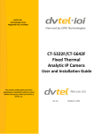
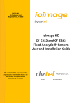
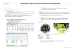
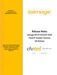
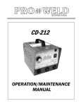
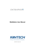
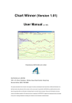
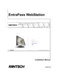
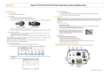
DVTEL INC. 65 Challenger Road Ridgefield Park, NJ 07660 CT-5322F/CT-5642F Fixed Thermal Analytic Camera Quick Installation Guide The contents of this guide may not be reproduced or reprinted in whole or in part without the express written permission of DVTEL, INC. Rev A1 September 24, 2015 CT-5322F/CT-5642F Fixed Thermal Analytic Camera QIG ii Document Information Table of Contents 1. Document Information ........................................................1 2. Introduction ........................................................................5 2.1. Package Contents .......................................................... 6 2.2. Connector Panel ............................................................ 8 3. Installation and Mounting ...................................................9 3.1. Preparation .................................................................. 10 3.2. Items Required for Installation That Are Not Supplied 10 3.3. Attach the Base Mount to the Camera ........................ 11 3.4. Connecting the Camera Cables .................................... 12 3.5. Mounting the Camera.................................................. 18 4. Accessing the Camera ........................................................ 19 4.1. Device Discovery .......................................................... 19 4.2. Viewing Live Video ....................................................... 20 5. Configuring Analytics ......................................................... 24 5.1. Configuring Depth Settings .......................................... 24 5.2. Configuring Rules ......................................................... 25 Contacting DVTEL .................................................................... 27 iii CT-5322F/CT-5642F Fixed Thermal Analytic Camera QIG List of Figures Figure 1: System Installation ........................................................... 5 Figure 2: Package Contents ............................................................ 6 Figure 3: Connector Panel .............................................................. 8 Figure 4: Recommended Tools ..................................................... 11 Figure 5: Attaching the Base Mount .............................................. 11 Figure 6: Cordgrip Parts ................................................................ 12 Figure 7: Cables Inserted Through Locking Nut ........................... 12 Figure 8: Rubber Grommet ........................................................... 13 Figure 9: Wires Inserted through Grommet .................................. 13 Figure 10: Rubber Grommet Inserted into Cordgrip ..................... 13 Figure 11: Assembling Sealing Nut ............................................... 14 Figure 12: Tightening the Locking Nut .......................................... 14 Figure 14: Power Wires with Ferrite .............................................. 15 Figure 16: Camera with Ferrites Installed for Power Supply......... 15 Figure 15: Back Cover and White Desiccant ................................ 16 Figure 16: Covering the Connector Panel ..................................... 17 Figure 17: Solar Shroud and Stem Bumpers ................................ 17 Figure 18: Fully Assembled Camera ............................................. 18 Figure 19: ActiveX Plug-in Message ............................................. 20 Figure 20: Render.cab Plug-in Dialog Box .................................... 20 Figure 21: Windows Restart Dialog Box ....................................... 21 Figure 22: View Screen ................................................................. 21 Figure 23: Depth Screen ............................................................... 24 Figure 24: Rules Screen ............................................................... 25 iv Document Information 1. Document Information Document Scope and Purpose The purpose of this document is to provide instructions and installation procedures for physically connecting the ioi Thermal CT-5322F/CT-5642F fixed cameras. After completing the physical installation, additional setup and configurations are required before video analysis and detection can commence. Note: This document is intended for use by technical users who have a basic understanding of CCTV camera/video equipment and LAN/WAN network connections. Remarque: Ce document est destiné aux utilisateurs techniciens qui possèdent des connaissances de base des équipements vidéo/caméras de télésurveillance et des connexions aux réseaux LAN/WAN. Warning: Installation must follow safety, standards, and electrical codes as well as the laws that apply where the units are being installed. Avertissement: L'installation doit respecter les consignes de sécurité, les normes et les codes électriques, ainsi que la législation en vigueur sur le lieu d'implantation des unités. 1 CT-5322F/CT-5642F Fixed Thermal Analytic Camera QIG Proprietary Rights and Non-Disclosure This guide is delivered subject to the following restrictions and conditions: This document contains proprietary information belonging to DVTEL, Inc. This information is supplied solely for the purpose of assisting explicitly the licensee of the DVTEL units. No part of this document contents may be used for any other purpose, disclosed to any third party or reproduced by any means, electronic or mechanical, without the express prior written permission of DVTEL, Inc. DVTEL, Inc. makes no representations whatsoever about any other products or trademarks mentioned in the manual. © DVTEL, Inc. 2015. All rights reserved. Legal and Environmental Information This product contains technology controlled under the U.S. Export Administration Regulations (EAR). Diversion contrary to U.S. law is prohibited. This product has been tested and found to comply with the limits of FCC (47 CFR) Part 15, Subpart B, Class A and CES-003. This product complies with the European RoHS directive. Disclaimer Users of DVTEL products accept full responsibility for ensuring the suitability and considering the role of the product detection capabilities and their limitation as they apply to their unique site requirements. DVTEL, Inc. and its agents make no guarantees or warranties to the suitability for the users’ intended use. DVTEL, Inc. accepts no responsibility for improper use or incomplete security and safety measures. Failure in part or in whole of the installer, owner, or user in any way to follow the prescribed procedures or to heed WARNINGS and CAUTIONS shall absolve DVTEL, Inc. and its agents from any resulting liability. Specifications and information in this guide are subject to change without notice. Electrical Safety Notice and Warnings SAVE ALL SAFETY AND OPERATING INSTRUCTIONS FOR FUTURE USE. Although the unit is designed and manufactured in compliance with all applicable safety standards, certain hazards are present during the installation of this equipment. 2 Document Information Camera Warnings Warning: 1. Only qualified trained personnel should service and repair this equipment. 2. Observe local codes and laws and ensure that installation and operation are in accordance with fire, security and safety standards. 3. The unit’s cover is an essential part of the product. Do not open or remove it. Operating the unit without the cover poses a risk of fire and shock hazards. 4. Do not disassemble the unit or remove screws. There are no user serviceable parts inside the unit. 5. Operating the camera at voltage levels outside the specified range may result in permanent damage to the unit and void the product warranty. 6. The camera electronics and electronic interfaces are sensitive to electrostatic discharge. Follow appropriate ESD procedures when handling the camera and during installation. 7. Be sure not to expose the camera head to strong sunlight, which could cause the camera to overheat. 8. This product must be connected to an IEEE 802.at-compliant POE+ power source, or a UL listed Class 2 power supply rated 12-24 VDC or 24 VAC, minimum 20W. IEEE 802.3af PoE is NOT supported. 9. For PoE+ installations, we strongly recommend using STP cabling and an earth grounded end point to ensure proper ESD immunity. For installations powered by AC or DC, a properly earth grounded power source is strongly recommended. Any other installation method may leave the camera at risk and void the warranty. 10. If you use a power supply, make sure that the connection matches the positive and negative polarity on the unit, and protect against static electricity, ground faults and power surges. 3 CT-5322F/CT-5642F Fixed Thermal Analytic Camera QIG Avertissements relatifs à la Caméra Avertissement: 1. Seul un technicien formé et qualifié est autorisé à entretenir et à réparer cet équipement. 2. Respectez les codes et réglementations locaux, et assurez-vous que l'installation et l'utilisation sont conformes aux normes contre l'incendie et de sécurité. 3. Le cache de l'unité est une partie essentielle du produit. Ne les ouvrez et ne les retirez pas. L'utilisation de l'unité sans cache présente un risque d'incendie et de choc électrique. 4. Ne démontez pas l'unité et ne retirez pas ses vis. Aucune pièce se trouvant à l'intérieur de l'unité ne nécessite un entretien par l'utilisateur. 5. Toute utilisation de la caméra à des niveaux de tension n'étant pas compris dans la fourchette indiquée peut endommager l'unité de façon permanente et peut annuler la validité de la garantie du produit. 6. L'électronique et les interfaces électroniques de la caméra sont sensibles aux décharges électrostatiques. Suivez les procédures ESD adéquates lors de toute manipulation de la caméra et au cours de son installation. 7. Assurez-vous de ne pas exposer la tête de la caméra aux rayons de soleil intenses qui pourraient surchauffer la caméra. 8. Ce produit doit être connecté à une source d'alimentation par IEEE 802.at (PoE+) ou à une alimentation UL de Classe 2 de 1224 V CC ou 24 V AC, 20W minimum. IEEE 802.3af PoE est pas pris en charge. 9. Pour les installations PoE+, nous recommandons fortement d'utiliser des câbles STP et une liaison à la terre pour assurer l'immunité face aux décharges électrostatiques. Pour les installations alimentées par AC ou CC, une source d'alimentation reliée à la terre est fortement recommandée. Toute autre méthode d'installation peut comporter des risques pour la caméra et annuler la garantie. 10. Si vous utilisez une alimentation, assurez-vous que le branchement à l'alimentation corresponde aux polarités positive et négative sur l'unité, et protéger l'unité contre l'électricité statique, les défauts de mise à la terre et les surtensions. 4 Introduction 2. Introduction This document provides information about the ioi Thermal CT-5322F/ CT-5642F fixed-mount, fixed focal length thermal camera that includes integrated video analytics. The NTSC/PAL camera system is a hybrid analog/ Internet Protocol (IP) networked solution that supports the Open Network Video Interface Forum (ONVIF™) Profile S standard. Figure 1: System Installation 5 CT-5322F/CT-5642F Fixed Thermal Analytic Camera QIG 2.1. Package Contents The unit package contains the following items: Figure 2: Package Contents 6 Item QTY Description 1 1 2 3 4 5 6 7 8 9 10 1 1 1 1 8 3 1 1 3 CT-5322F/CT-5642F Fixed Thermal Analytic Camera (with 90° RG179BU BNC adapter attached to the connector panel) Base mount Back cover Solar shroud Liquid tight cordgrip #6 32 x 5/8” screws (including spares) Stem bumpers ( including one spare) White silica gel desiccant for installation Rubber O-ring (shown as installed on the cordgrip) Sealing washers with gasket (including one spare) Introduction In addition, the following items are supplied: QTY Description 1 Package of four terminal connectors: 6-pin for alarms and relay; 4-pin for audio (not currently supported); 3-pin for power and ground; and 2-pin for RS-485 (not currently supported) 1 Locking Nut 2 Ferrites (for power and alarm leads) 1 Quick Installation Guide (this document) Note: Use PoE+ or a 12-24VDC or 24 VAC power source that supplies 20W. IEEE 802.3af PoE is NOT supported. Related information: ioi Thermal CT-5322F/CT-5642F User and Installation Guide HTML Edition Units User’s Guide DNA User Manual 7 CT-5322F/CT-5642F Fixed Thermal Analytic Camera QIG 2.2. Connector Panel The connector panel includes the following items: Figure 3: Connector Panel 8 Item Comment Video Port Connects the analog video coax cable between the camera and an analog DVR. Ethernet Port Connects the network cable between the camera and the network switch for network communication and powering the unit. The PoE+ supply requires minimum 20W. IEEE 802.3af PoE is NOT supported. Reset Button Resets the unit to full factory defaults. Hold for at least 6 secs. Alarm In Pins Connects two alarm inputs via the supplied 6-pin connector to the marked 1, 2, and ground pins. Each alarm input pin should also be connected to the ground pin (i.e., pin 1 + ground, or pin 2 + ground). Relay Out Pins Connects the 6-pin connector to the marked NC, C, and NO pins. The NC and NO pin should also be connected to the C pin (i.e., NC + C, or NO + C). Audio In/Out Not currently supported. RS-485 Pins Not currently supported. AC/DC Pins Connects a male 3-pin connector from an AC or DC power supply to the unit’s + (positive), – (negative), and ground leads. Installation and Mounting 3. Installation and Mounting The physical installation of the unit is the first phase of making the unit operational in a security plan. The goal is to physically place the unit, connect it to other devices in the system, and to establish IP network connectivity. When finished with the physical installation, refer to the ioimage Thermal CT-5322F/CT-5642F User and Installation Guide to complete the second phase of installation, which is the setup and configuration of the unit. Caution: To avoid damage from overheating or unit failure, assure that there is sufficient temperature regulation to support the unit’s cooling/ heating requirements. Operating temperature should be kept in the range -40° to 60°C (-40° to 140°F), with no more than 95% noncondensing humidity. Attention: Afin d'éviter tout dommage dû à une surchauffe ou toute panne de l'unité, assurez-vous que la régulation de température est suffisante pour répondre aux exigences de l'unité (refroidissement/chauffage). La température de fonctionnement doit être maintenue dans la plage de température spécifiée pour le produit (-40° à 60°C/-40° à 140°F, sans condensation d'humidité supérieur à 95%). 9 CT-5322F/CT-5642F Fixed Thermal Analytic Camera QIG 3.1. Preparation Read the instructions in this chapter thoroughly before installing the camera. Following are additional considerations for outdoor installation: Always use weatherproof equipment, such as boxes, receptacles, connectors, etc. For electrical wiring, use the properly rated sheathed cables for conditions to which the cable will be exposed (for example, moisture, heat, UV, physical requirements, etc.). Plan ahead to determine where to install infrastructure weatherproof equipment. Whenever possible, ground components to an outdoor ground. Use best security practices to design and maintain secured camera access, communications infrastructure, tamper-proof outdoor boxes, etc. To minimize the effects of EMI (electromagnetic interference) and RFI (radio frequency interference), consult your reseller. 3.2. Items Required for Installation That Are Not Supplied The following items are required for installation, but are not included in the package: 10 Power source (PoE+ switch, 12-24VDC or 24VAC power supply) Shielded Twisted Pair (STP) cable if using a PoE+ switch Cat 5 Ethernet cable for network connection without a PoE+ switch Tripod or mounting bracket for mounting the camera One #2 Phillips head screwdriver One open-end, 1-inch (25.4mm) wrench or adjustable wrench One 6-inch (152mm) scale or ruler Electric or manual torque screwdriver set to 10 inch-pounds (1.23 Newton meters) Installation and Mounting Hex wrench RJ45 connector RJ45 crimping tool Coax cable Coax cable cutter/stripper BNC connector BNC crimping tool Figure 4: Recommended Tools 3.3. Attach the Base Mount to the Camera To attach the base mount to the camera Screw the base mount into the camera body with eight #6 screws. Figure 5: Attaching the Base Mount Using the electric screwdriver, tighten the fasteners to about 8 inchpounds (0.904 newton meters) of torque. 11 CT-5322F/CT-5642F Fixed Thermal Analytic Camera QIG 3.4. Connecting the Camera Cables In order to connect the camera to the network, take the analog video cable, network cable, power supply leads (if an AC or DC supply is used), alarm, and relay wiring from the wall at the installation site. In order to connect the wires to the connectors on the camera’s connector panel, they must be wired through the supplied cordgrip. Wires must be fed from the wall through the camera’s mounting assembly, through the opening on the underside of the camera, through the camera body, and out of the opening on the camera’s connector panel. The wires then must be attached to connectors before attaching them to the connector panel. To connect the camera cabling Disconnect power from any previously installed cables. Remove the cordgrip parts from the package. Figure 6: Cordgrip Parts Feed the wires through the locking nut, then through the camera body and out of the opening on connector panel. Figure 7: Cables Inserted Through Locking Nut Feed the wires through the cordgrip body as seen in the picture above. 12 Installation and Mounting Place the orange O-ring over the cordgrip and feed the wires through the cordgrip body and sealing nut as seen in Figure 9. Insert the Ethernet cable through the center opening of the rubber grommet. Then insert the other wires through the small holes in the rubber. The wires should be spaced several holes apart. Nineteen (19) AWG is recommended for the power leads. Twenty (20) AWG is recommended for all wires other than the Ethernet and video cables. The flat side of the grommet should be on the inside of the cordgrip. Figure 8: Rubber Grommet Figure 9: Wires Inserted through Grommet If needed, use a #2 Phillips head screwdriver to widen the hole in the center of the rubber grommet. If needed, pierce the smaller holes on the outer perimeter of the rubber grommet for the video cable, AC/DC supply wiring, alarm, and relay leads. Measure about 4-1/2” (114mm) of cable from the end of all wires to the rubber grommet. Push the rubber grommet into the cordgrip body so that the grommet is flush with the slotted side of the body and the flat side of the sealing nut is facing it. Figure 10: Rubber Grommet Inserted into Cordgrip 13 CT-5322F/CT-5642F Fixed Thermal Analytic Camera QIG Insert the wires through the sealing nut and screw the nut so that it is closes tightly on the cordgrip body. Use the hex wrench to tighten the nut to 50-55 inch-pounds (5.65-6.215 newton meters) of torque so that the cordgrip is securely fastened. Figure 11: Assembling Sealing Nut Insert the assembled cordgrip into the opening on the connector panel. The side including the exposed screw thread and rubber O-ring should be inserted first. Hand-tighten the locking nut inside the camera body. Figure 12: Tightening the Locking Nut Use the hex wrench to tighten the nut to approximately 8 in-lbs. (0.9 newton meters) of torque so that the cordgrip is securely fastened. Using a striping tool, attach an RJ45 connector (not supplied) to the Ethernet cable and an RJ179BU male BNC crimp connector (not supplied) to the video cable. Crimp the wires onto the connectors. 14 Installation and Mounting If the camera is connected to an alarm or a 12 or 24 volt power supply, it is necessary to insert the wires through the supplied ferrites in order to comply with EMI emission standards. Figure 13: Power Wires with Ferrite Attach the supplied plugs to the wires. Crimp the wires onto the connectors. If using a power supply, connect the 3-pin male terminal block connector from the power supply to the AC/DC power input. Insert the connectors and plugs into the connector panel. Figure 14: Camera with Ferrites Installed for Power Supply 15 CT-5322F/CT-5642F Fixed Thermal Analytic Camera QIG Note: If you use a PoE+ switch, in order to ensure a proper earth ground between the camera and the PoE+ switch, we strongly recommend using Shielded Twisted Pair (STP) cabling. Installations of ioimage Thermal cameras with STP cabling and a properly earth grounded PoE+ switch are tested to comply with industry immunity standards for electrostatic discharge (ESD). Any other installation method may leave the camera at risk and void the warranty. Reconnect power to the cables. Check for a steady LED indication on the Ethernet cable RJ45 connector to confirm connection to the IP network. The status LED indicators are: LED 1: Steady green for 10MB connection or flashing green for activity. LED 2: Steady amber for 100MB connection or flashing amber for activity. Insert the supplied white desiccant inside the back cover. Figure 15: Back Cover and White Desiccant 16 Installation and Mounting Close the rear cover over the assembled connector panel by aligning the notch on the cover with the notch in the camera body. If necessary, reinsert any excess cable into the body of the camera. Figure 16: Covering the Connector Panel Attach the back cover to the camera. Screws are pre-installed in the back cover. Tighten the two fasteners to approximately 8 in-lbs. (0.904 newton meters) of torque. Assemble the two rubber stem bumpers onto the two detents in the concave surface of the solar shroud. Figure 17: Solar Shroud and Stem Bumpers Snap the solar shroud over the camera body. The camera is ready for mounting. 17 CT-5322F/CT-5642F Fixed Thermal Analytic Camera QIG Figure 18: Fully Assembled Camera 3.5. Mounting the Camera The camera can be mounted on a tripod or on a base mount or four-hole bracket. 18 For tripod mounting, use the tripod adapter, which is available as an accessory. For base mounting, install the camera base mount on a standard flat side bracket (not provided) using the supplied #6 32 x 5/8” screws. Accessing the Camera 4. Accessing the Camera After installing the ioi Thermal CT-5322F/CT-5642F camera, use the camera’s web Interface to make configuration changes and to view live video. In order to make these changes, connect to the camera from any PC on your network. The PC must meet the following requirements: Windows 7, Windows 8, or Windows 8.1 operating system IE 8, 9, 10, or 11 browser 4.1. Device Discovery We recommend using DVTEL’s DNA tool to discover the camera on the network. Note: Use a DHCP server to facilitate discovery of the unit’s IP Address. Confirm that Use DHCP is checked in DNA’s Assign IP dialog box. By default, when the camera powers on, it attempts to obtain an IP address from a DHCP server in the network. If the camera cannot obtain an IP address through DHCP within a reasonable time, it will default to an IP address of 192.168.0.200 and a subnet mask of 255.255.255.0. In the event that you do not have access to the DHCP server: 1. 2. Set 192.168.0.11 as the IP address for the client PC. Use the Windows Network tool to locate the camera and set the static IP address. To discover devices using DNA Download the DNA utility from the DVTEL Partner Portal or DVTEL web site at http://www.dvtel.com/services-support/firmware-software/. Click the DNA icon and run the DNA utility (DNA.exe). DNA discovers all devices on the VLAN. Assign IP address to the device. Click the Login icon and enter login credentials for the devices. 19 CT-5322F/CT-5642F Fixed Thermal Analytic Camera QIG Enter the unit’s IP address in your browser (IE 8, 9, 10, or 11). When the Login window opens, enter the unit’s default user name and password (“admin” and “admin”). 4.2. Viewing Live Video After logging in for the first time or loading a new firmware version, a dialog box opens in the user interface, requesting you to install the ActiveX plug. After installing the plug-in, the View screen is displayed. To enable the ActiveX plug-in From the web interface, click the on-screen link to install the ActiveX plugin. Figure 19: ActiveX Plug-in Message Click Install on the Internet Explorer dialog box requesting to you to install the render.cab plug-in. Occasionally, after installing the plugin, a Windows dialog box opens. Figure 20: Render.cab Plug-in Dialog Box 20 Accessing the Camera If you receive this message, click Restart Now on the Windows dialog box to restart the computer. The computer restarts. Figure 21: Windows Restart Dialog Box Open your browser and enter the camera’s IP address. The Login window opens. Enter your user credentials. The View screen is displayed. Figure 22: View Screen 21 CT-5322F/CT-5642F Fixed Thermal Analytic Camera QIG The View screen includes the following icons, buttons, controls and menus: Item Description Video Stream Select the video stream: H.264, MJPEG, or HTTP JPEG. You can select multiple video streams from a single camera, which open in separate browser windows. Snapshot View Size 22 HTTP JPEG is recommended for: Accessing a unit that is located behind a firewall at a remote site Transmitting video via HTTP over remote networks with low bandwidth Remote configuration of the unit over the web If you have difficulty viewing the video in H.264 Click the icon to take a snapshot of the image. Adjust the video viewing window to the following sizes: 160 x 120, 320 x 240, or 640 x 480 (default). The icon above the top-right corner of the image indicates whether constant recording is active (red dot) or inactive (gray dot). Accessing the Camera Item Description AGC Automatic Gain Control (AGC) adjusts the gain and level of the entire scene in real-time. From the dropdown menu, select a mode: Freeze – Turns off/freezes AGC at its current level. Auto – provides an image with optimum average contrast and brightness. ICE – Enhanced gain control/Image Contrast Enhancement (ICE) that prevents the darkening of scenes and reduces detector noise when hot objects appear in lowcontrast indoor scenes. It also amplifies detector noise to enhance images of highcontrast outdoor scenes. Move the slider to adjust the strength of the AGC/ICE settings. The range is from 0-7. The higher the number, the better the picture. The default is 4. Move the slider to adjust the contrast. The range is from 0-100. The higher the number, the higher the contrast. The default is 50. Move the slider to adjust the brightness. The range is from 0-100. The higher the number, the brighter the picture. The default is 50. Enables you to select how to display hot and cold pixels. Select one of the following settings: White Hot – Hot pixels are shown as white and cold pixels are shown as black. Black Hot – Hot pixels are shown as black and cold pixels are shown as white. Normally, an NUC is performed automatically to compensate for temperature variations. Click this button to manually force a Non Uniformity Correction. The NUC interval can also be set using the maintenance/camera functions menu. Click this button to arm or disarm the camera. The camera disarms itself when you configure the unit. Click this button to clear alarms that you have set. The alarm status is indicated under the viewing window. ICE Contrast Brightness Polarity Non Uniformity Correction (NUC) Arm/Disarm Clear Alarms 23 CT-5322F/CT-5642F Fixed Thermal Analytic Camera QIG 5. Configuring Analytics The Analytics tab contains menus for defining the camera’s field of view depth and detection rules. Figure 23: Depth Screen 5.1. Configuring Depth Settings Follow these steps in the Analytics > Depth screen wizard to configure depth settings: 1. From the Live View window, select Analytics > Depth > Solo Setup. The following instructions are displayed on the screen. 2. On the Solo Setup control keypad, click the Start Recording icon and select a folder where to store the clip. 3. Press Stop Recording. 4. Proceed to the tab for Step 1: Ground & Height to place ground and height markers and guidelines in the clip. 24 Configuring Analytics 5. Click Browse to load and view the clip. Navigate the clip and add human markers. 6. Exit Clip mode and return to Live mode by pressing the round Play button on the control panel located to the left of the monitor. Continue setting depth by proceeding to the tabs for Steps 2-4. Follow the onscreen instructions. Expand the Help section included with each step for detailed information. Verify that the settings provide an accurate representation of the sizes and distances in the scene. When finished, click Apply to save settings. Refer to the HTML Edition Units User’s Guide for detailed instructions on configuring these settings. 5.2. Configuring Rules The Analytics > Rules tab enables you to define detection rules according to the type of detection you want to be notified about. Figure 24: Rules Screen 25 CT-5322F/CT-5642F Fixed Thermal Analytic Camera QIG Detection occurs when one or more detection rules are active, the camera is in Arm mode, and the scenario on the video (scene) fits the detection criterion specified. You can activate rules, modify settings, delete, or add a new rule. Rules are selected by clicking the Attributes tab. The Basic tab displays minimal information for the rule. The Advanced tab displays additional information for the rule. From the Navigation Bar, select Analytics > Rules. A rule for detecting humans or vehicles entering the scene (blue masked area) is defined by default. To create a new rule: 1. Click New. 2. Select the rule type. 3. Draw on the video scene where you want the detection to take place. 4. Define the attributes for detection. 5. When finished, click Apply to save the settings. 26 Contacting DVTEL Contacting DVTEL To contact us, write us at [email protected] or contact your local office. CORPORATE HEADQUARTERS DVTEL, Inc. 65 Challenger Road Ridgefield Park, NJ 07660, USA Tel: 201.368.9700 Fax: 201.368.2615 Order Fax: 201.712.0343 [email protected] ASIA PACIFIC REGION DVTEL 111 North Bridge Road, #27-01 Peninsula Plaza Singapore 079098 Tel: +65 6389 1815 Fax: +65 6491 5660 [email protected] ANZ AND THE PACIFIC ISLANDS DVTEL 37 Victoria Street Henley Beach SA 5022, Australia Tel: +61 8 8235 9211 Fax: +61 8 8235 9255 Mobile: +61 419 850 166 [email protected] EMEA DVTEL UK Ltd. 7 Lancaster Court, Coronation Road High Wycombe HP12 3TD England Tel: +44 (0) 1494 430240 Fax: +44 (0) 1494 446928 [email protected] INDIA AND SAARC, GULF REGION DVTEL India Pvt., Ltd. 303, SSR Corporate Park Mathura Road Faridabad 121002, Haryana, India Tel: +91 (129) 431 5031 Fax: +91 (129) 431 5033 [email protected] CENTRAL AND LATIN AMERICA DVTEL Mexico S.A.P.I. de C.V. Felipe Villanueva No. 10 Col. Guadalupe Inn México, D.F. 01020 México Tel: +5255 5580 5618 Fax: +52 55 8503 4299 [email protected] DVTEL NORTH ASIA 2404, 24/F, World-Wide House 19 Des Voeux Road Central Hong Kong Tel: +852 3667 9295 Mobile: +852 9479 4195 [email protected] DVTEL北亞地區 香港中環德輔道中19號 環球大廈2404室 電話: +852 3667 9295 手提: +852 9479 4195 電郵: [email protected] To request the latest versions of firmware and software or to download other product-related documents, visit http://www.dvtel.com/support. If you have obtained a login, go to our support gateway. For assistance, email us at [email protected] or phone 1-888-DVTEL77. 27