1
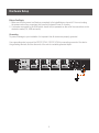
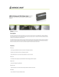
Installation Guide
2/4 port DVI Secure KVM
GCS1212TAA / 1214TAA
PART NO. M1191 / M1192
1
Table of Contents
Conventions
4
Package Content
4
System Requirements
5
Components
6
Hardware Setup
8
Operation
11
Specifications
12
Federal Communications Commission
(FCC) Statement
14
CE Compliance
14
Technical Support
14
Limited Warranty
15
Contact
15
3
Conventions
This manual uses the following conventions: Monospaced Indicates text that you should key in.
[ ] Indicates keys you should press. For example, [Enter] means to press the Enter key. If keys need to be
chorded, they appear together in the same bracket with a plus sign between them: [Ctrl+Alt].
1. Numbered lists represent procedures with sequential steps.
• Bullet lists provide information, but do not involve sequential steps.
––> Indicates selecting the option (on a menu or dialog box, for example), that comes next. For example,
Start ––> Run means to open the Start menu, and then select Run.
Indicates critical information.
Package Content
1 x 2/4-Port dual link DVI secure KVM switch
1 x Power cord
1 x User manual
1 x Registration Form
Verify all the components are present and that nothing was damaged in shipping. If you encounter a problem,
contact your dealer, or IOGEAR.
Read this manual thoroughly and follow the installation and operation procedures carefully to prevent any
damage to the unit, and / or any of the devices connected to it.
4
System Requirements
Console:
• DVI monitor
• USB keyboard and mouse
• Speakers and microphone
Computer:
• DVI port - Single or Dual Link DVI video card
• Type “A” USB port
*Dual Link DVI-D USB 2.0 KVM Cables sold separately (G2L7D02UD, G2L7D03UD, G2L7D05UD)
Operating Systems:
• Windows XP, Vista, 7
• Mac OS X or greater
• Sun Solaris
• Linux, UNIX and other USB supported systems**
**Additional drivers and support may be needed
5
Components
Front View
1
Secure KVM Switch
4-Port Dual-Link DVI
Secure KVM Switch
2
3
4
5
4-Port Dual-Link DVI
Rear View
7
6
8
9
10
11
Note: The GCS1214TAA has been used in these illustrations. The front and rear panels of the
GCS1212TAA and the GCS1214TAA are the same, except the GCS1212TAA has two ports/port
selection pushbuttons and the GCS1214TAA has four.
6
12
1. Port LEDs- The Port LEDs are built into the Port Selection Pushbuttons. Online – Lights green to
indicate that the computer attached to its corresponding port is up and running. Note: The green light
for a given port is lit for as long as there is a powered on USB connection between the KVM switch and
computer. Selected – Lights orange to indicate that the computer attached to its corresponding port
has the KVM.Note: The Selected LEDs will flash constantly when a chassis intrusion is detected. See
Chassis Intrusion Detection, page 12 for further details.
2. Port Selection Pushbuttons- Pressing a Port Selection Pushbuttonbrings the focus to the computer
attached to its corresponding port.
3. Reset Button- Press this to reset the GCS1212TAA / GCS1214TAA to the default settings.
4. Console Audio Ports- The cables from your main speakers and main microphone plug in here. The
speakers and microphone plugged in here have priority over those in the rear panel.
5. Power LED- Lights blue to indicate that the GCS1212TAA / GCS1214TAA is powered on.
6. USB Console Ports- Your USB keyboard and mouse plug into these ports.
7. Console Audio Ports- The cables from your main speakers and main microphone plug in here. The
speakers and microphone plugged in here have priority over those in the rear panel.
8. Console
Monitor Port- The cable from your console monitor plugs in here.
9. KVM
Port Section- The custom KVM cables that attach to your computers plug in here.
10. Power Switch- To turn the power on and off.
11. Power Socket- Where the power cord is plugged in.
12. Grounding Screw- See Grounding, page 8 for further details.
7
Hardware Setup
Secure KVM Switch
4-Port Dual-Link DVI
Before You Begin
1. Make sure that the power to all devices connected to the installation are turned off. You must unplug
the power cords of any computers that have the Keyboard Power On function.
2. A computer connected to the KVM switch should only be powered on after all of the connections to the
device are made (DVI, USB and audio).
Grounding
To prevent damage to your installation it is important that all devices are properly grounded.
Use a grounding wire to ground the GCS1212TAA / GCS1214TAA by connecting one end of the wire to
the grounding terminal, and the other end of the wire to a suitable grounded object.
8
To set up your GCS1212TAA / GCS1214TAA installation, refer to the installation diagram on the following
page (the numbers in the diagrams correspond to the steps, below), and do the following:
1. Plug your USB keyboard and USB mouse into the USB console ports located on the unit’s rear panel.
2. Plug your console monitor into the DVI console port located in the unit’s rear panel and power on the
monitor.
3. Plug your microphone and speakers into the console microphone and speaker jacks located on the
unit’s front or rear panel. The microphone and speakers plugged into the front panel have priority over
those in the rear panel.
4. Using a KVM cable set (not supplied in the package and should be purchased separately), plug the
DVI connector into any available DVI socket in the KVM port section of the switch, then plug the
accompanying USB, microphone and speaker connectors into their corresponding USB, microphone,
and speaker sockets.
5. At the other end of the cable, plug the USB, video, microphone, and speaker cables into their
respective ports on the computer.
6. Check that the USB seal is still attached to the CAC reader port to prevent unintended usage.
7. Plug the female end of the power cord into the GCS1212TAA / GCS1214TAA’s power socket; plug the
male end into an AC power source.
8. Powering On.
9
Installation Diagram
10
Operation
Powering On
When you power on your computers, GCS1212TAA / GCS1214TAA emulates both a mouse and keyboard
on each port and allows your computers to boot normally. The default selected port at switch power on is
the lowest port with a computer connected. The selected computer will be displayed on the console monitor.
Note: The default connection is determined by the lowest numbered DVI connection that is powered on.
Manual Switching
For increased security, GCS1212TAA / GCS1214TAA offers manual port-switching only. This is achieved
by pressing the port selection pushbuttons located on the unit’s front panel.
Press and release a port selection pushbutton to bring the KVM focus to the computer attached to its
corresponding port (see Port ID Numbering, below). The Selected LED lights orange to indicate that the
computer attached to its corresponding port has the KVM.
Port ID Numbering
Each KVM port on the GCS1212TAA / GCS1214TAA is assigned a port number (1–2 for the GCS1212TAA; 1–4 for the GCS1214TAA). The port numbers are marked on the rear of the switch. See Rear
View, page 6. The port ID of a computer is derived from the KVM port number it is connected to.
LED Display
In addition to the Power LED, the GCS1212TAA / GCS1214TAA has port LEDs (Online and Selected) that
are built into the port selection pushbuttons to indicate port operating status, as shown in the table below:
LED
Indication
Power
Lights blue to indicate that the GCS1212TAA / GCS1214TAA is powered on
Online
Lights green to indicate that the computer attached to its corresponding port is
up and running. Note: The green light for a given port is lit for as long as there is a
powered on USB connection between the KVM switch and computer.
Selected
Lights orange to indicate that the computer attached to its corresponding port has
the KVM.
Chassis Intrusion Detection
To help prevent malicious tampering with the GCS1212TAA / GCS1214TAA, the switch becomes inoperable and the Selected LEDs flash constantly when a chassis intrusion, such as the cover being removed,
is detected.
CAC Reader
The usage of the CAC Reader port is not covered in this evaluation. Make sure the USB seal is in place to
maintain the integrity of this device.
11
Specifications
Function
GCS1212TAA
GCS1214TAA
Computer Connections
2
4
Port Selection
Pushbutton
Connectors
Console
Keyboard
1 x USB Type-A F (Black)
Video
1 x DVI-I Dual Link F (White)
Mouse
Audio
Computer
Switches
Emulation
2 x Mini Stereo Jack F (Green;1 x front panel,1 x
rear panel)
Microphone
2 x Mini Stereo Jack F (Pink;1 x front panel,1 x
rear panel)
Keyboard/Mouse
2 x USB Type-B F
4 x USB Type-B F
Video
2 x DVI-I Dual Link F
(White)
4 x DVI-I Dual Link F
(White)
Speaker
2 x Mini Stereo Jack F
(Green)
4 x Mini Stereo Jack F
(Green)
Microphone
2 x Mini Stereo Jack
F (Pink)
4 x Mini Stereo Jack F
(Pink)
Audio
LEDs
1 x USB Type-A F (Black)
Speaker
Power
1 x 3-prong AC Socket
Power
1 (Blue)
On Line
2 (Green)
4 (Green)
Selected
2 (Orange)
4 (Orange)
Port Selection
2 x Pushbuttons
4 x Pushbuttons
Reset
1 x Semi-recessed Pushbutton
Power
1 x Rocker
Keyboard / Mouse
USB
Video
DVI Dual Link: 2560x1600; DVI Single Link:
1920x1200 DVI-A: 2048x1536
I/P Rating
100–240V AC; 50/60 Hz; 0.5A
12
Function
GCS1212TAA
GCS1214TAA
Power Consumption
120V / 5.1W;
230V / 5.1W
120V / 6.1W;
230V / 5.7W
Environment
Operating Temp.
0–40ºC
Storage Temp
-20–60ºC
Humidity
0–80% RH, Non-condensing
Housing
Metal
Weight
3.85 Lbs
Dimensions (L x W x H)
13” x 6” x 2”
Physical
Properties
13
4.00 Lbs
Federal Communications Commission (FCC) Statement
This equipment has been tested and found to comply with the limits for a Class B digital device, pursuant to
Part 15 of the FCC Rules. These limits are designed to provide reasonable protection against harmful interference in a residential setting. This product generates, uses, and can radiate radio frequency energy and, if
not installed and used as directed, it may cause harmful interference to radio communications. Although this
product complies with the limits for a Class B digital device, there is no guarantee that interference will not
occur in a particular installation.
CE Compliance
This device has been tested and found to comply with the following European Union directives:
Electromagnetic Capability (89/336/EMC), Low Voltage (73/23/EEC) and R&TTED (1999/5/EC).
Technical Support
If you need technical support, please check out our IOGEAR Tech Info Library (T.I.L.) at www.iogear.com/
support for the latest tips, tricks, and troubleshooting. The IOGEAR T.I.L. was designed to provide you
with the latest technical information about our products. Most of the answers to your questions can be
found here, so please try it out before contacting technical support.
Technical support is available Monday through Friday from 8:00 am to 5:00 pm PST and can be reached
at (949) 453-8782 and (866) 946-4327 or by email [email protected].
14
Limited Warranty
IN NO EVENT SHALL THE DIRECT VENDOR’S LIABILITY FOR DIRECT, INDIRECT, SPECIAL,
INCIDENTAL OR CONSEQUENTIAL DAMAGES RESULTING FROM THE USE OF THE PRODUCT, DISK
OR ITS DOCUMENTATION EXCEED THE PRICE PAID FOR THE PRODUCT.
The direct vendor makes no warranty or representation, expressed, implied, or statutory with respect to
the contents or use of this documentation, and especially disclaims its quality, performance,
merchantability, or fitness for any particular purpose.
The direct vendor also reserves the right to revise or update the device or documentation without
obligation to notify any individual or entity of such revisions, or updates. For further inquires please contact
your direct vendor.
Contact
IOGEAR
19641 DaVinci
Foothill Ranch, CA 92610
P 949.453.8782
F 949.453.8785
Visit us at:
www.iogear.com
© 2011 IOGEAR®. All Rights reserved. Part No. M1191 / M1192
IOGEAR and the IOGEAR logo are trademarks or registered trademarks of IOGEAR, Inc. Microsoft and Windows are registered trademarks of
Microsoft Corporation. IBM is a registered trademark of International Business Machines, Inc. IOGEAR makes no warranty of any kind with regards to
the information presented in this document. All information furnished here is for informational purposes only and is subject to change without notice.
IOGEAR assumes no responsibility for any inaccuracies or errors that may appear in this document.
15
About Us
FUN
IOGEAR offers connectivity solutions that are innovative, fun, and stylish,
helping people enjoy daily life using our high technology products.
GREEN
IOGEAR is an environmentally conscious company that emphasizes the
importance of conserving natural resources. The use of our technology
solutions helps reduce electronic waste.
© 2011 IOGEAR