1
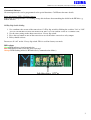
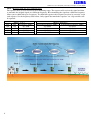
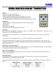
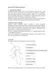
ELSEMA
434MHz Transceiver with Optically Isolated Inputs and High Power Relay Outputs
434MHz Transceivers
MCTR43401: 1 Optically Isolated Input and 1 Relay Output
MCTR43402: 2 Optically Isolated Inputs and 2 Relay Outputs
MCTR43404: 4 Optically Isolated Inputs and 4 Relay Outputs
Features
• Wide supply connection, 10 - 28 Volts AC or DC
• Reverse polarity protection, EMI, surge and transient protection
• Up to 4 input channels with simultaneous channel transmission
• Up to 4 relay outputs with simultaneous channel reception
• Over 800 metres operating range with repeater mode
• User selectable relay modes, momentary or latching
• Easy connection using pluggable terminal blocks
• Crystal controlled for high stability and accuracy
• On-board LED’s for the Inputs and Outputs
• Four user selectable transmission modes
o Simple transmit and receive
o Transmit and receive with return signal acknowledgment
o Repeater with one-way communication
o Repeater with two-way communication
Applications
Process controls in factories, warehouses and farms
Water or sewerage tank level monitoring
Equipment and machinery control
Irrigation and pump controls
Security
Description
The transceiver operates in the 434MHz frequency band with 10mW of RF power. Using Elsema’s ANT433M
antenna it is possible to get up to 800 metres line of sight communications. This range can be doubled by
configuring an extra MCTR43404R as a repeater. An Elsema 434Micro antenna is provided for free with all
MCTR series transceivers and can be used for testing short range applications less than 80 metres.
Supply
The transceiver power supply can be AC or DC. The power supply has built-in protections against EMI noise,
surges and transients. Even if there is a power failure on one transceiver the built-in handshake
acknowledgments will ensure that the transceivers inputs and outputs are returned to the same state as before
the power failure.
Solar Power:
Use one of Elsema’s 10 Watt or 20 Watt Solar Panels with the BACH charger to supply the transceivers with
solar and battery power.
1
ELSEMA
434MHz Transceiver with Optically Isolated Inputs and High Power Relay Outputs
Products in the Range
MCTR43401R
1 Input / Output
MCTR43402R
2 Inputs / Outputs
MCTR43404R
4 Inputs / Outputs
MCTR43401RE
MCTR43402RE
MCTR43404RE
Transceivers in a
weatherproof Case
SP10-10 Watts
SP20-20 Watts
20W Solar panel
Signal Strength Indicator
The 1 and 2 channel transceivers have three orange SS LED’s on the board. These orange LED’s indicated the
signal strength.
3 LED’s on
2 LED’s on
1 LED on
-70dBm
-80dBm
-90dBm
Strong Signal
Good Signal
Signal OK
Reliable Operating Conditions
Reliable Operating Conditions
Operating Conditions Ok
Noise Strength Indicator
If more than 1 SS LED is “ON” without a valid transmission this indicates that there is noise on the frequency
selected. Change dipswitch 1 and 2 of the 12-way dipswitch to select a different frequency.
Sw1
Off
On
Off
On
Sw2
Off
Off
On
On
Frequency (MHz)
433.3020
433.9164
434.5308
433.3020
Inputs and Outputs
Inputs
There are up to four normally open inputs. When these inputs are closed (Shorted to Ground/Negative) the
signal is transmitted.
Output Modes
Relay output on the receiver can function in either momentary or latching mode. By default the mode is set to
momentary. Modes selectable from the 4-way dipswitch. Dipswitch 1 corresponds to relay channel 1 and
dipswitch 2 corresponds to relay channel 2 and so on.
Factory Default = Momentary
Momentary - Output is active for as long as the transmitter button is pressed.
This is a standard mode on most automatic gates or garage door openers.
Latching
2
- Output remains active until next press of the transmitter button.
Similar to switching "on" and "off" a light.
ELSEMA
434MHz Transceiver with Optically Isolated Inputs and High Power Relay Outputs
Customised Software
Custom output modes can be programmed to do special functions. Call Elsema for more details.
Input and Outputs LED’s Flashing Orange
If the Input and Output LED’s are flashing orange this indicates that something has failed in the RF link, e.g.
broken antenna.
12-Way Dip Switch Coding
1. Set a random code on one of the transceivers 12-Way dip switch by flicking the switches "On" or "Off".
(DO NOT USE THE DEFAULT FACTORY SETTING FOR THE 12-WAY DIP SWITCH AS THIS IS A COMMON CODE)
2. Set the same setting on the other transceivers 12-way dip switch.
3. Press the test button on one of the transceivers to test the other transceivers relay output
4. Relay should activate.
Do not use all “off” on the 12-way dip switch. This is used for factory test mode.
LED colours
Green LED indicates signal transmission
Red LED indicates that a relay has been activated.
Orange LED flashing indicates RF link failed (Communication failure)
3
ELSEMA
434MHz Transceiver with Optically Isolated Inputs and High Power Relay Outputs
Transmission Modes
The transceivers can be user configured to four different transmission modes.
Mode 1 Simple transmit and receiver
Transceiver is used to send the signal one-way to activate a relay. Used for simple on/off functions. See
diagram below.
Both transceivers should be set to Mode 1
4
ELSEMA
434MHz Transceiver with Optically Isolated Inputs and High Power Relay Outputs
Mode 2 Transmit and receive with acknowledgment
Transceiver is used to transmit a signal to another transceiver with a return acknowledgment. If a
transceiver receives a valid signal it will return a signal back to the first transceiver and a relay and LED is
turned “On”. This LED will indicate which relay is “on”. See diagram below.
With mode 2 you will need to set the momentary or flip flop mode the same in both transceivers and one
of the transceivers should be set as a Master and the other transceiver to a Slave. Remove the Slave
jumper to setup as a slave. Both transceivers should be set to Mode 2.
5
ELSEMA
434MHz Transceiver with Optically Isolated Inputs and High Power Relay Outputs
Mode 3 Repeater with one way communication
The repeater mode is used to increase the transmitting range. The repeater will receiver the signal and then
re-transmits the original signal on a different frequency. Re-transmitting the signal on a different frequency
allows you to chain link up to 2 repeaters. To chain link repeaters the frequency needs to be correctly set on
each repeater. See the frequency table below. Only signals that match the repeaters 3 to 8 dip switches will
be repeated.
Sw1
Off
On
Off
On
6
Mode 1, 2 & 4
Sw2
Frequency (MHz)
Off
433.3020
Off
433.9164
On
434.5308
On
433.3020
Mode 3 (Repeater)
Receiving Frequency (MHz)
Transmitting Frequency (MHz)
433.3020
433.9164
433.9164
434.5308
434.5308
433.3020
433.3020
433.9164
ELSEMA
434MHz Transceiver with Optically Isolated Inputs and High Power Relay Outputs
Mode 4 Repeater with return acknowledgment
The repeater will receive the signal and then re-transmits the original signal on the same frequency. The
final transceiver will send back a signal, via the repeater to indicate which output is activated. Only one
repeater can be used in this mode.
With mode 4 you will need to set the momentary or flip flop mode the same in both transceivers and one
of the transceivers should be set as a Master and the other transceiver to a Slave. Remove the Slave
jumper to setup as a slave. Both transceivers should be set to Mode 2 and the repeater to Mode 4.
Slave Jumper
Remove the jumper on the pins labelled SLAVE. This will setup the transceiver to a slave. See picture below.
7
ELSEMA
434MHz Transceiver with Optically Isolated Inputs and High Power Relay Outputs
Changing the Transmission Modes
On the back of the transceivers there are 2 pairs of square pads. An outer and an inner pair of pads that are used
to change the mode of the transceiver. See the picture below.
Transmission Mode 1: No link on any of the pads sets both transceivers to Mode 1.
Transmission Mode 2: Outer pads shorted sets both transceivers to Mode 2.
Transmission Mode 3: Inner pads shorted sets the transceiver to Mode 3.
Transmission Mode 4: Both Outer and Inner pads are shorted sets the transceivers to Mode 4.
Warning: These pads are electrostatic sensitive. Earth yourself and the soldering iron on a metal surface
before soldering the pads. Failure may result in the IC being permanently damaged.
Operating Frequencies
Dipswitch 1 and 2 set the operating frequency. Since the frequencies are all within the 434MHz band it is not
recommended to operate a second installation within a 300 metres radius of the first installation.
Sw1
Off
On
Off
On
Sw2
Off
Off
On
On
Frequency (MHz)
433.3020
433.9164
434.5308
433.3020
Customised Software
Customer specific programs can be written to do special functions. Call Elsema for more details.
Antenna
The transceiver has a 50 ohms SMA connector to allow a proper 434MHz antenna to be connected. Elsema
stocks the ANT433M or ANT433S, 434MHz antennas.
Case
The transceivers can be supplied with an IP66 rated case for outdoor and indoor use. The product part number
ending in “E” includes the IP66 rated cases. MCTR43401RE, MCTR43402RE and MCTR43404RE.
8
ELSEMA
434MHz Transceiver with Optically Isolated Inputs and High Power Relay Outputs
Application Notes
Here a security guard is monitoring a transceiver that has three lights and a buzzer connected. The three lights
represent three different locations and the buzzer alerts the guard that an alarm has been activated.
At each of the three locations you have a transceiver. At these locations you wire a single button that will
activate two inputs in parallel, one for the light and the other for the buzzer. This signal will be transmitted to
the security guard house.
9
ELSEMA
434MHz Transceiver with Optically Isolated Inputs and High Power Relay Outputs
Technical Specifications
Supply Voltage
10 - 28 Volts AC or DC
Can use Elsema AC power supply PP12 or PP24
Solar Panel Backup SP10 for 10 Watt Solar Panel, SP20 for 20 Watt Solar Panel
Battery Backup BACH12 for 12 volt charging or BACH24 for 24 Volt charging.
Current Consumption
27 mA stand by at 12VDC, 45 mA with 1 relay “On” or 100 mA with 4 relays
“On”
Frequencies 433.3020, 433.9164 or 434.5308 MHz
Operating Temperature -20°C to 70°C
R.F. Output Power 10mW into 50 ohms SMA connector
Sensitivity 2uV (For output to switch on)
Type of Demodulation Frequency Modulation (FM)
ID System Setting 12-way dip switch
Inputs Pluggable screw type terminal block. Inputs are Normally Open (NO)
Outputs Change over relay outputs rated at 8 Amps 240VAC
Relay Contacts Common (C) , Normally Closed (NC) & Normally Open (NO)
LED’s
Dual coloured LED’s to indicate inputs and outputs status
Antenna Elsema type ANT433M. A 433Micro antenna is provided for free with each
transceiver for short range application testing of less than 80 metres.
Mounting QM150 Quick Mount
Mounting hole size 3.97 mm or 5/32"
Case Optional Plastic Case with IP66 rating
Dimensions 130 x 70 x 26 mm
Weight 117 grams
Operating Range Over 800 metres operating range with repeater mode
10
ELSEMA
434MHz Transceiver with Optically Isolated Inputs and High Power Relay Outputs
Block Diagram
MCTR43401R
MCTR43402R
11
ELSEMA
434MHz Transceiver with Optically Isolated Inputs and High Power Relay Outputs
MCTR43404R
12
ELSEMA
434MHz Transceiver with Optically Isolated Inputs and High Power Relay Outputs
MCTR43404R, 12 or 24 VAC/DC Applications
13
ELSEMA
434MHz Transceiver with Optically Isolated Inputs and High Power Relay Outputs
MCTR43404R, 110 or 240 VAC Applications
Elsema Pty Ltd
31 Tarlington Place,
Smithfield, NSW 2164
Ph: 61 2 9609 4668
Fax: 61 2 9725 2663
Website: www.elsema.com
Distributed by:
User Manual 2nd Edition October 2011
14