1
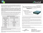
®
4. Products sold by Cellphone-Mate, Inc. shall not be considered defective or non-conforming to the
Buyers’ order if they satisfactorily fulfill the performance requirements that were published in the
product specification literature, or in accordance with samples provided by Cellphone-Mate, Inc. This
warranty shall not apply to any products or parts thereof which have been subject to accident,
negligence, alteration, abuse, or misuse. Cellphone-Mate, Inc. makes no warranty whatsoever in
respect to accessories or parts not supplied by it.
5. EXCEPT AS EXPRESSLY SET FORTH HEREIN, THERE ARE NO WARRANTIES, CONDITION
GUARANTEES OR REPRESENTATIONS AS TO MERCHANTABILITY, FITNESS FOR A PARTICULAR
PURPOSE OR OTHER WARRANTIES, CONDITIONS, GUARANTEES OR REPRESENTATIONS, WHETHER
EXPRESSED OR IMPLIED, IN LAW OR IN FACT, ORAL OR IN WRITING. CELLPHONE-MATE, INC.’S
AGGREGATE LIABILITY IN DAMAGES OR OTHERWISE SHALL NOT EXCEED THE PAYMENT, IF ANY,
RECEIVED BY CELLPHONE-MATE, INC. FOR THE UNIT OF PRODUCT OR SERVICE FURNISHED OR TO BE
FURNISHED, AS THE CASE MAY BE, WHICH IS THE SUBJECT OF CLAIM OR DISPUTE. IN NO EVENT
SHALL CELLPHONE-MATE, INC. BE LIABLE FOR INCIDENTAL, CONSEQUENTIAL, OR SPECIAL DAMAGES,
HOWSOEVER CAUSED.
6. All matters regarding this warranty shall be interpreted in accordance with the laws of the State of
California and any controversy that cannot be settled directly shall be settled by arbitration in
California in accordance with the rules then prevailing of the American Arbitration Association, and
judgment upon the award rendered may be entered in any court having jurisdiction thereof.
7. If one or more provisions provided herein are held to be invalid or unenforceable under applicable
law, then such provision shall be ineffective and excluded to the extent of such invalidity
or unenforceability without affecting in any way the remaining provisions hereof.
EFLEX-65 Specifications
Upl i nk Freq. Ra nge (MHz)
Downl i nk Freq. Ra nge
Supported s ta nda rds
Input/Output i mpeda nce
Avera ge ga i n
Noi s e figure
VSWR
AC Power Transformer
Ma x output power
Ca bl e
RF connectors
Power cons umption
Di mens i ons
Wei ght
FCC ID (USA)
Ca na da IC
1850-1910
824-849
1930-1990
869-894
CDMA, GSM, WCDMA, EDGE, HSPA
50Ω
Can Adjust from 15 to 65dB
5dB
≤2.0
Input AC110V, 60Hz; Output: DC12V/6V
3W Cellular / 2W PCS EIRP
CM400 or CM240
N Ma l e (both ends )
<20W
5.5” x 4.75” x 1.25”
1 lb 11 oz (765g)
RSNDUAL-62UNDER
7784A-D60UNDER
User Manual
Enhance Dual-Band Wireless
Adjustable Cellular Booster / Kit
CM-EFlex 65 *
▪ 65dB booster (Auto Shutdown)
▪ 110V AC power supply
▪ Velcro and screw mounting kit
*Outdoor and indoor antennas
and cables are required for
installation (purchased separately)
:
CM-EFlex
65 Kit *
▪ 65dB adjustable booster
▪ 30' CM400 cable
▪ 75' CM400 cable
▪ 288W outdoor omni antenna
▪ 222W indoor panel antenna
*also Include 110V AC power supply and screw mounting kit
Safety Information
The Federal Communications Commission (FCC) has tested this product and found it to comply
with their RF Exposure Requirements, pursuant to FCC Part 22 and 24.
To comply with the FCC RF exposure requirements, keep the human user’s body at least 8”
(20cm) from the indoor antenna of the booster.
Don't expose this product to extreme low or high temperature (-4°F or -20°C and 150°F or
70°C).
There are no consumer serviceable or modifiable parts inside this booster product. Alteration or
abuse of the booster or other components will void this product’s warranty, and could be
dangerous to the user.
Cellphone-Mate, Inc.
EFlex-65Kit (20121018) v1.1
888.365.MATE (6283) phone - (510)996-7250 fax
www.surecall.com
www.cellphone-mate.com
48346 Milmont Drive Fremont, CA 94538 (USA)
Using the Booster
Vehicle Use - Connecting & Using the Booster(Optional)
Step 1: When you receive the booster, the Cellular (800 MHz frequency) dial on the left and the PCS
(1900 MHz frequency) dial on the right should be each set at 65dB.
NOTE: Before turning on booster, set Cellular and PCS gain to the coverage space you are working
with in the chart below.
Gain(dB)
65
60
55
50
45
35
15
Cover Space(sq.ft)
3,000-6,000
2,000-4,000
1,500-2,000
1,000-1,500
500-1,000
For Car
Not Recommended
Antenna Seperation
60'-80'
50'-75'
40'-60'
35'-50'
15'-35'
3'-6'
Not Recommended
Step 2 : ALERT Light: After turning on the booster, the Alert lights will flash for 10 to 15 seconds on each
band. This is to let you know that each band is activated.
Step 3: If the ALERT lights continue to blink after the initial activation period, turn down the dial
above the respective blinking light by 5dB, or for example, from 65 to 60. If the ALERT light(s)
continue to flash, the booster will automatic shut down, then restart after 30 seconds.
NOTE: During this process of adjusting dBs for either band, continually monitor the bars on your cell
phone to see if the reception has improved or has decreased to its original setting before purchasing or
installing the booster.
WARNING: Never operate the booster with the red light on.
Safety Warning: The input voltage for the booster is 6V. DO NOT use this booster with a higher voltage
power supply, which could damage the booster and the user may also be injured.
In-Building Use - Connecting the Booster
Overview: The signal is received by the outside antenna from the cell tower, then amplified and
transmitted to your phone through the inside antenna. When the phone transmits, the signal is received
by the inside antenna, then amplified and transmitted to the cell tower through the outside antenna.
1. Connect the Inside Antenna: Mount the dome
antenna on the ceiling in a central location
where you want reception. Using the CM400
cable, connect the dome antenna to the side
of the booster marked “INSIDE”. Hand tighten.
2. Connect the Outside Antenna: The fiberglass
antenna is for outdoor use only. Select an
outside mounting location. For best performance,
try to keep the antenna on top of the house.
The outside antenna should be located in an
area with at least a 12” radius clear of obstructions, and other radiating elements. Using the CM400
cable, connect the outside antenna to the “OUTSIDE” connector of the booster and hand tighten it.
NOTE: Ideal separation distance between the inside and outside antennas is at least 75 feet apart with
a weak outside cell signal and the booster operating at full 65dB gain.
WARNING: The outside antenna must not be co-located or operating in conjunction with any other
antenna or booster.
3. Connect the Power Cord: Connect the power cord to the booster, and then connect the plug to 110V
AC power outlet. Make sure that all of the connections to the booster are tight and secure.
1. Connect the Outside Antenna: A magnetic antenna is for outdoor use only. Select an outside mounting
location. For best performance, keep the antenna on top of the vehicle. The outside antenna should
be located in an area with at least 12”of space on all sides that is free of obstructions and other
radiating elements such as a radio antenna. Screw the outside antenna to the outdoor connector of
the booster, and then tighten it until snug. Do not over-tighten.
WARNING: The outside antenna must not be co-located or operating in conjunction.with any other
antenna or booster.
2. Connect the Inside Antenna: A patch antenna is intended for indoor use only. Do not mount on a surface
within 4”of metal. Screw the patch antenna cable to the INSIDE connector on the booster. This booster
is designed to be used while the cell phone is in a cradle or held free.
Note: The inside and outside antennas should be at least 6’apart, if possible.
3. Connect the Power Cord: Connect the DC power cord to the booster before plugging it into the cigarette
lighter adapter. Verify that all of the connections to the booster are tight and secure.
4. Before plugging in the car charger, make sure both the Cellular and PCS dials are turned down to 35dB.
When booster is on, the LED light will glow, indicating that the booster is ready to use.
OPTIONAL – MOUNTING THE BOOSTER
Determine the location where your booster will be placed. Clean the intended surface and allow it to
dry. Peel the protective paper from the back of the hook sides of the Velcro. Press the adhesive side
of the Velcro strips into place on the bottom of the booster, one strip on each end. Wait 5 minutes for
the adhesive to set before attaching the loop side of the Velcro to the hook side. The adhesive bond
will reach its maximum strength after 24 hours.
With both of the Velcro loop and hook pieces attached to the back of the booster, peel the protective
paper off of the back of the loop strips. Press the entire booster into its mounting place. Wait 5
minutes for the adhesive to set. Make sure the booster is firmly seated. To remove the booster, rotate
it across the Velcro – do not pull the booster or cables.
Troubleshooting
If the booster interferes with your radio or other electronic receivers, move the booster further away
from those devices. For a list of Frequently Asked Questions and a complete, up-to-date
Troubleshooting Guide, please visit our website at: www.surecall.com. You may also consult a
Cellphone-Mate technical specialist directly by emailing us at [email protected].
Warranty
1. Cellphone-Mate, Inc. warrants to the Buyer that each of its products, when shipped will be free from
defects in material and workmanship and will perform in full accordance with applicable
specifications. The limit of liability under this warranty is, at Cellphone-Mate, Inc.’s option, to repair or
replace any product or part thereof which shall within TWO YEARS of purchase as determined by
examination by Cellphone-Mate, Inc., prove defective in material and/or workmanship. Warranty
returns must first be authorized in writing by Cellphone-Mate, Inc. Disassembly of any Cellphone-Mate,
Inc. product by anyone other than an authorized representative of Cellphone-Mate, Inc. voids this
warranty in its entirety. Cellphone-Mate, Inc. reserves the right to make changes in any of its products
without incurring any obligation to make the same changes on previously delivered products.
2. As a condition to the warranties provided for herein, the Buyer will prepay the shipping charges for
all products returned to Cellphone-Mate, Inc. for repair and Cellphone-Mate, Inc. will pay the return
shipping with the exception of product returned from outside the United States in which case the
Buyer will pay the shipping charges.
3. The Buyer will pay the cost of inspecting and testing any goods returned under the warranty or
otherwise which are found to meet the applicable specifications or which are not defective or not
covered by this warranty.