1
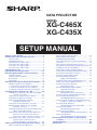
DATA PROJECTOR
MODEL
XG-C465X
XG-C435X
SETUP MANUAL
Setting up the Screen .......................................... 2
Screen Size and Projection Distance ................ 3
Throw Distance ....................................................... 3
Standard Zoom Lens .............................................. 4
Wide-zoom Lens (AN-C12MZ) ............................... 5
Tele-zoom Lens (AN-C18MZ) ................................. 6
Tele-zoom Lens (AN-C27MZ) ................................. 7
Tele-zoom Lens (AN-C41MZ) ................................. 8
Changing the Lens .............................................. 9
Connecting Pin Assignments .......................... 11
RS-232C Specifications and Commands ........ 13
Computer control .................................................. 13
Communication conditions ................................... 13
Basic format .......................................................... 13
Commands ........................................................... 14
Setting up the Projector Network Environment ... 18
Network settings on the computer ....................... 18
1. Connecting the Projector to a Computer .......... 19
2. Setting an IP Address for the Computer .......... 20
3. Setting up a Network Connection for the Projector .... 22
Controlling the Projector via LAN .................... 24
Controlling the Projector Using Internet Explorer
(Version 5.0 or later) ................................... 24
Confirming the Projector Status (Status) ............. 25
Controlling the Projector (Control) ....................... 25
Setting and Adjusting the Projector
(Settings & Adjustments) ............................ 26
Setting the Security (Network – Security) ............ 26
Making General Settings for the Network
(Network - General) .................................... 27
Setting for Sending E-mail when an Error Occurs
(Mail – Originator Settings) ........................ 27
Setting Error Items and Destination Addresses
to which E-mail is to be Sent when an
Error Occurs (Mail – Recipient Settings) ... 28
Setting Error Items and the URL that are to be
Displayed when an Error Occurs
(Service & Support – Access URL) ........... 28
Setting up the Projector Using RS-232C or Telnet .... 29
When Connecting Using RS-232C ....................... 29
When Connecting Using Telnet ............................ 30
SETUP MENU (Main Menu) ................................. 31
ADVANCED SETUP MENU ................................. 31
View Setting Detail List ([V]View All Setting) ....... 32
Set Items ............................................................... 32
Save Settings and Quit ([S]Save & Quit) ............. 33
Quit without Saving Settings ([Q]Quit Unchanged) .. 33
IP Address Setting ([1]IP Address) ...................... 34
Subnet Mask Setting ([2]Subnet Mask) ............... 34
Default Gateway Setting ([3]Default Gateway) .... 34
User Name Setting ([4]User Name) ..................... 34
Password Setting ([5]Password) .......................... 35
RS-232C Baud Rate Setting
([6]RS-232C Baud Rate) ............................ 35
Projector Name Setting ([7]Projector Name) ....... 35
DHCP Client Setting ([8]DHCP Client) ................. 35
Disconnecting All Connections
([D]Disconnect All) ..................................... 36
Entering ADVANCED SETUP MENU
([A]Advanced Setup) .................................. 36
Setting Auto Logout Time
(ADVANCED[1]Auto Logout Time) ............. 36
Data Port Setting (ADVANCED[2]Data Port) ....... 36
Carrying out Network Ping Test
(ADVANCED[5]Network Ping Test) ............ 37
Setting of Accept IP Address (ADVANCED[6]Accept
IP Addr(1) – [8]Accept IP Addr(3)) ................. 37
Accepting All IP Addresses
(ADVANCED[9]Accept All IP Addr) ............ 37
Setting of Search Port
(ADVANCED[0]Search Port) ...................... 38
Return to Default Settings
(ADVANCED[!]Restore Default Setting) ..... 38
Return to Main Menu
(ADVANCED[Q]Return to Main Menu) ....... 38
Resetting the Lamp Timer of the Projector
via LAN ....................................................... 39
Troubleshooting ................................................. 41
Dimensions ........................................................ 44
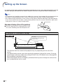
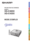
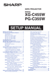
Setting up the Screen
For optimal image quality, position the projector perpendicular to the screen with the projector’s feet flat
and level. Doing so will eliminate the need for Keystone correction and provide the best image quality.
Note
• The projector lens should be centered in the middle of the screen. If the horizontal line passing through the
lens center is not perpendicular to the screen, the image will be distorted, making viewing difficult.
• For an optimal image, position the screen so that it is not in direct sunlight or room light. Light falling directly
on the screen washes out the colors, making viewing difficult. Close the curtains and dim the lights when
setting up the screen in a sunny or bright room.
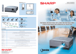
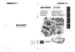
Standard Setup (Front Projection)
■ Place the projector at the required distance from
the screen according to the desired picture size.
Example of standard setup
Side View
Base line:
Horizontal line passing through
the lens center
Screen
Lens center
H
L: Projection distance
• The distance from the screen to the projector may vary depending on the size of the
screen.
• The default setting can be used, when placing the projector in front of the screen. If the pro-
jected image is reversed, readjust the setting to “Front” in the “PRJ Mode” menu. (See page 52
of the projector’s operation manual.)
• Place the projector so that an imaginary horizontal line that passes through the center of the
lens is perpendicular to the screen.
-2
Screen Size and Projection Distance
The projection screen size varies according to the distance from the lens of the projector to the screen.
The optional lenses from Sharp are also available for specialized application. Please see your nearest Sharp
Authorized Projector Dealer to details on all the lenses. (Refer to the lens operation manual when using a
lens.)
Install the projector so that projected images are projected onto the screen at the optimum size by referring
to the table. Use the values in the table as a reference when installing the projector.
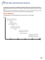
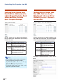
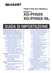
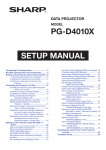
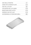
Throw Distance
The graph below is for 100 inches (254 cm) screen with 4:3 normal mode.
Screen
Wide-zoom lens (AN-C12MZ)
9'11"–12'5" (3.0 m–3.8 m)
Throw distance ratio 1:1.5–1.9
Standard zoom lens
11'9"–14'1" (3.6 m–4.3 m)
Throw distance ratio 1:1.8–2.1
Tele-zoom lens (AN-C18MZ)
14'10"–18'10" (4.5 m–5.7 m)
Throw distance ratio 1:2.2–2.8
Tele-zoom lens (AN-C27MZ)
22'–33'11" (6.7 m–10.3 m)
Throw distance ratio 1:3.3–5.1
Tele-zoom lens (AN-C41MZ)
34'5"–48'4" (10.5 m–14.7 m)
Throw distance ratio 1:5.2–7.2
3.0
6.0
9.1
12.2
10
20
30
40
15.2 (m)
50 (ft)
-3
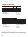
Screen Size and Projection Distance
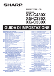
Standard Zoom Lens
F1.7-F1.9, f=28.0-33.6 mm
NORMAL Mode (4:3)
Picture (Screen) size
Diag. [χ]
500''
300''
270''
250''
200''
150''
100''
84''
80''
72''
60''
40''
χ:
L:
L1:
L2:
H:
(1270 cm)
(762 cm)
(686 cm)
(635 cm)
(508 cm)
(381 cm)
(254 cm)
(213 cm)
(203 cm)
(183 cm)
(152 cm)
(102 cm)
Width
1016 cm
610 cm
549 cm
508 cm
406 cm
305 cm
203 cm
171 cm
163 cm
146 cm
122 cm
81 cm
(400'')
(240'')
(216'')
(200'')
(160'')
(120'')
(80'')
(67'')
(64'')
(58'')
(48'')
(32'')
Projection distance [L]
Height
762 cm
457 cm
411 cm
381 cm
305 cm
229 cm
152 cm
128 cm
122 cm
110 cm
91 cm
61 cm
(300'')
(180'')
(162'')
(150'')
(120'')
(90'')
(60'')
(50'')
(48'')
(43'')
(36'')
(24'')
Minimum [L1]
17.9 m
10.7 m
9.6 m
8.9 m
7.1 m
5.4 m
3.6 m
3.0 m
2.9 m
2.6 m
2.1 m
1.4 m
(58' 7")
(35' 2")
(31' 8")
(29' 3")
(23' 5")
(17' 7")
(11' 9")
(9' 10")
(9' 4")
(8' 5")
(7')
(4' 8")
Maximum [L2]
21.4 m
12.9 m
11.6 m
10.7 m
8.6 m
6.4 m
4.3 m
3.6 m
3.4 m
3.1 m
2.6 m
1.7 m
(70' 4")
(42' 2")
(38')
(35' 2")
(28' 1")
(21' 1")
(14' 1")
(11' 10")
(11' 3")
(10' 1")
(8' 5")
(5' 7")
Picture size (diag.) (in/cm)
Projection distance(m/ft)
Minimum projection distance (m/ft)
Maximum projection distance (m/ft)
Distance from the lens center to the bottom of the image (cm/in)
Distance from the lens center
to the bottom of the image [H]
–76 cm
–46 cm
–41 cm
–38 cm
–30 cm
–23 cm
–15 cm
–13 cm
–12 cm
–11 cm
–9 cm
–6 cm
(–30")
(–18")
(–16 13/64")
(–15")
(–12")
(–9")
(–6")
(–5 3/64")
(–4 51/64")
(–4 5/16")
(–3 19/32")
(–2 13/32")
The formula for picture size and projection distance
[m/cm]
L1 (m) = 0.03571χ
L2 (m) = 0.04286χ
H (cm) = –0.1524χ
[Feet/inches]
L1 (ft) = 0.03571χ / 0.3048
L2 (ft) = 0.04286χ / 0.3048
H (in) = –0.1524χ / 2.54
STRETCH Mode (16:9)
Picture (Screen) size
Diag. [χ]
450''
300''
250''
225''
200''
150''
133''
106''
100''
92''
84''
80''
72''
60''
40''
χ:
L:
L1:
L2:
H:
S:
(1143 cm)
(762 cm)
(635 cm)
(572 cm)
(508 cm)
(381 cm)
(338 cm)
(269 cm)
(254 cm)
(234 cm)
(213 cm)
(203 cm)
(183 cm)
(152 cm)
(102 cm)
Width
996 cm
664 cm
553 cm
498 cm
443 cm
332 cm
294 cm
235 cm
221 cm
204 cm
186 cm
177 cm
159 cm
133 cm
89 cm
(392'')
(261'')
(218'')
(196'')
(174'')
(131'')
(116'')
(92'')
(87'')
(80'')
(73'')
(70'')
(63'')
(52'')
(35'')
Projection distance [L]
Height
560 cm
374 cm
311 cm
280 cm
249 cm
187 cm
166 cm
132 cm
125 cm
115 cm
105 cm
100 cm
90 cm
75 cm
50 cm
(221'')
(147'')
(123'')
(110'')
(98'')
(74'')
(65'')
(52'')
(49'')
(45'')
(41'')
(39'')
(35'')
(29'')
(20'')
Minimum [L1]
17.5 m
11.7 m
9.7 m
8.8 m
7.8 m
5.8 m
5.2 m
4.1 m
3.9 m
3.6 m
3.3 m
3.1 m
2.8 m
2.3 m
1.6 m
(57' 5")
(38' 3")
(31' 11")
(28' 9")
(25' 6")
(19' 2")
(17')
(13' 6")
(12' 9")
(11' 9")
(10' 9")
(10' 3")
(9' 2")
(7' 8")
(5' 1")
Picture size (diag.) (in/cm)
Projection distance(m/ft)
Minimum projection distance (m/ft)
Maximum projection distance (m/ft)
Distance from the lens center to the bottom of the image (cm/in)
Adjustable range of image position (cm/in)
Maximum [L2]
21.0 m
14.0 m
11.7 m
10.5 m
9.3 m
7.0 m
6.2 m
4.9 m
4.7 m
4.3 m
3.9 m
3.7 m
3.4 m
2.8 m
1.9 m
(68' 11")
(45' 11")
(38' 4")
(34' 6")
(30' 8")
(23')
(20' 4")
(16' 3")
(15' 4")
(14' 1")
(12' 10")
(12' 3")
(11')
(9' 2")
(6' 2")
Distance from the lens center
to the bottom of the image [H]
19 cm
12 cm
10 cm
9 cm
8 cm
6 cm
6 cm
4 cm
4 cm
4 cm
3 cm
3 cm
3 cm
2 cm
2 cm
(7 23/64")
(4 29/32")
(4 5/64")
(3 43/64")
(3 17/64")
(2 29/64")
(2 11/64")
(1 47/64")
(1 41/64")
(1 1/2")
(1 3/8")
(1 5/16")
(1 11/64")
(63/64")
(21/32")
Adjustable range of
image position [S]
±93 cm
±62 cm
±52 cm
±47 cm
±42 cm
±31 cm
±28 cm
±22 cm
±21 cm
±19 cm
±17 cm
±17 cm
±15 cm
±12 cm
±8 cm
(±36 49/64")
(±24 33/64")
(±20 27/64")
(±18 25/64")
(±16 11/32")
(±12 1/4")
(±10 7/8")
(±8 21/32")
(±8 11/64")
(±7 33/64")
(±6 55/64")
(±6 17/32")
(±5 57/64")
(±4 29/32")
(±3 17/64")
The formula for picture size and projection distance
[m/cm]
L1 (m) = 0.0389χ
L2 (m) = 0.04669χ
H (cm) = 0.04151χ
S (cm) = ±0.20754χ
[Feet/inches]
L1 (ft) = 0.0389χ / 0.3048
L2 (ft) = 0.04669χ / 0.3048
H (in) = 0.04151χ / 2.54
S (in) = ±0.20754χ / 2.54
Note
• Allow a margin of error in the value in the diagrams above.
• When the distance from the lens center to the bottom of the image [H] is a negative number, this indicates
that the bottom of the image is below the lens center.
-4
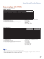
Screen Size and Projection Distance
Wide-zoom Lens (AN-C12MZ)
F2.2-F2.7, f=24.5-30.7 mm
NORMAL Mode (4:3)
Picture (Screen) size
Diag. [χ]
250''
200''
150''
100''
84''
80''
72''
60''
40''
χ:
L:
L1:
L2:
H:
(635 cm)
(508 cm)
(381 cm)
(254 cm)
(213 cm)
(203 cm)
(183 cm)
(152 cm)
(102 cm)
Width
Projection distance [L]
Height
508 cm (200'') 381 cm (150'')
406 cm (160'') 305 cm (120'')
305 cm (120'') 229 cm (90'')
203 cm (80'') 152 cm (60'')
171 cm (67'') 128 cm (50'')
163 cm (64'') 122 cm (48'')
146 cm (58'') 110 cm (43'')
122 cm (48'')
91 cm (36'')
81 cm (32'')
61 cm (24'')
Minimum [L1]
7.5 m
6.0 m
4.5 m
3.0 m
2.5 m
2.4 m
2.2 m
1.8 m
1.2 m
(24' 9")
(19' 10")
(14' 10")
(9' 11")
(8' 4")
(7' 11")
(7' 2")
(5' 11")
(4')
Maximum [L2]
9.5 m
7.6 m
5.7 m
3.8 m
3.2 m
3.0 m
2.7 m
2.3 m
1.5 m
(31')
(24' 10")
(18' 7")
(12' 5")
(10' 5")
(9' 11")
(8' 11")
(7' 5")
(5')
Picture size (diag.) (in/cm)
Projection distance(m/ft)
Minimum projection distance (m/ft)
Maximum projection distance (m/ft)
Distance from the lens center to the bottom of the image (cm/in)
Distance from the lens center
to the bottom of the image [H]
–38 cm
–30 cm
–23 cm
–15 cm
–13 cm
–12 cm
–11 cm
–9 cm
–6 cm
(–15")
(–12")
(–9")
(–6")
(–5 3/64")
(–4 51/64")
(–4 5/16")
(–3 19/32")
(–2 13/32")
The formula for picture size and projection distance
[m/cm]
L1 (m) = 0.03019χ
L2 (m) = 0.03783χ
H (cm) = –0.1524χ
[Feet/inches]
L1 (ft) = 0.03019χ / 0.3048
L2 (ft) = 0.03783χ / 0.3048
H (in) = –0.1524χ / 2.54
STRETCH Mode (16:9)
Picture (Screen) size
Diag. [χ]
225''
200''
150''
133''
106''
100''
92''
84''
80''
72''
60''
40''
χ:
L:
L1:
L2:
H:
S:
(572 cm)
(508 cm)
(381 cm)
(338 cm)
(269 cm)
(254 cm)
(234 cm)
(213 cm)
(203 cm)
(183 cm)
(152 cm)
(102 cm)
Width
498 cm
443 cm
332 cm
294 cm
235 cm
221 cm
204 cm
186 cm
177 cm
159 cm
133 cm
89 cm
(196'')
(174'')
(131'')
(116'')
(92'')
(87'')
(80'')
(73'')
(70'')
(63'')
(52'')
(35'')
Projection distance [L]
Height
280 cm (110'')
249 cm (98'')
187 cm (74'')
166 cm (65'')
132 cm (52'')
125 cm (49'')
115 cm (45'')
105 cm (41'')
100 cm (39'')
90 cm (35'')
75 cm (29'')
50 cm (20'')
Minimum [L1]
7.4 m
6.6 m
4.9 m
4.4 m
3.5 m
3.3 m
3.0 m
2.8 m
2.6 m
2.4 m
2.0 m
1.3 m
(24' 3")
(21' 7")
(16' 2")
(14' 4")
(11' 5")
(10' 9")
(9' 11")
(9' 1")
(8' 8")
(7' 9")
(6' 6")
(4' 4")
Picture size (diag.) (in/cm)
Projection distance(m/ft)
Minimum projection distance (m/ft)
Maximum projection distance (m/ft)
Distance from the lens center to the bottom of the image (cm/in)
Adjustable range of image position (cm/in)
Maximum [L2]
9.3 m
8.2 m
6.2 m
5.5 m
4.4 m
4.1 m
3.8 m
3.5 m
3.3 m
3.0 m
2.5 m
1.6 m
(30' 5")
(27')
(20' 3")
(18')
(14' 4")
(13' 6")
(12' 5")
(11' 4")
(10' 10")
(9' 9")
(8' 1")
(5' 5")
Distance from the lens center
to the bottom of the image [H]
9 cm
8 cm
6 cm
6 cm
4 cm
4 cm
4 cm
3 cm
3 cm
3 cm
2 cm
2 cm
(3 43/64")
(3 17/64")
(2 29/64")
(2 11/64")
(1 47/64")
(1 41/64")
(1 1/2")
(1 3/8")
(1 5/16")
(1 11/64")
(63/64")
(21/32")
Adjustable range of
image position [S]
±47 cm
±42 cm
±31 cm
±28 cm
±22 cm
±21 cm
±19 cm
±17 cm
±17 cm
±15 cm
±12 cm
±8 cm
(±18 25/64")
(±16 11/32")
(±12 1/4")
(±10 7/8")
(±8 21/32")
(±8 11/64")
(±7 33/64")
(±6 55/64")
(±6 17/32")
(±5 57/64")
(±4 29/32")
(±3 17/64")
The formula for picture size and projection distance
[m/cm]
L1 (m) = 0.03289χ
L2 (m) = 0.04121χ
H (cm) = 0.04151χ
S (cm) = ±0.20754χ
[Feet/inches]
L1 (ft) = 0.03289χ / 0.3048
L2 (ft) = 0.04121χ / 0.3048
H (in) = 0.04151χ / 2.54
S (in) = ±0.20754χ / 2.54
Note
• Allow a margin of error in the value in the diagrams above.
• When the distance from the lens center to the bottom of the image [H] is a negative number, this indicates
that the bottom of the image is below the lens center.
-5
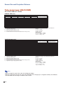
Screen Size and Projection Distance
Tele-zoom Lens (AN-C18MZ)
F1.7-F2.2, f=36.5-46.3 mm
NORMAL Mode (4:3)
Picture (Screen) size
Diag. [χ]
250''
200''
150''
100''
84''
80''
72''
60''
40''
χ:
L:
L1:
L2:
H:
(635 cm)
(508 cm)
(381 cm)
(254 cm)
(213 cm)
(203 cm)
(183 cm)
(152 cm)
(102 cm)
Projection distance [L]
Width
Height
508 cm (200'')
406 cm (160'')
305 cm (120'')
203 cm (80'')
171 cm (67'')
163 cm (64'')
146 cm (58'')
122 cm (48'')
81 cm (32'')
381 cm (150'')
305 cm (120'')
229 cm (90'')
152 cm (60'')
128 cm (50'')
122 cm (48'')
110 cm (43'')
91 cm (36'')
61 cm (24'')
Minimum [L1]
11.3 m
9.1 m
6.8 m
4.5 m
3.8 m
3.6 m
3.3 m
2.7 m
1.8 m
Maximum [L2]
(37' 2") 14.4 m (47' 1")
(29' 9") 11.5 m (37' 8")
(22' 3") 8.6 m (28' 3")
(14' 10") 5.7 m (18' 10")
(12' 6") 4.8 m (15' 10")
(11' 11") 4.6 m (15' 1")
(10' 8") 4.1 m (13' 7")
(8' 11") 3.4 m (11' 4")
(5' 11") 2.3 m (7' 6")
Picture size (diag.) (in/cm)
Projection distance(m/ft)
Minimum projection distance (m/ft)
Maximum projection distance (m/ft)
Distance from the lens center to the bottom of the image (cm/in)
Distance from the lens center
to the bottom of the image [H]
–38 cm
–30 cm
–23 cm
–15 cm
–13 cm
–12 cm
–11 cm
–9 cm
–6 cm
(–15")
(–12")
(–9")
(–6")
(–5 3/64")
(–4 51/64")
(–4 5/16")
(–3 19/32")
(–2 13/32")
The formula for picture size and projection distance
[m/cm]
L1 (m) = 0.04529χ
L2 (m) = 0.05745χ
H1 (cm) = –0.1524χ
[Feet/inches]
L1 (ft) = 0.04529χ / 0.3048
L2 (ft) = 0.05745χ / 0.3048
H (in) = –0.1524χ / 2.54
STRETCH Mode (16:9)
Picture (Screen) size
Diag. [χ]
225''
200''
150''
133''
106''
100''
92''
84''
80''
72''
60''
40''
χ:
L:
L1:
L2:
H:
S:
(572 cm)
(508 cm)
(381 cm)
(338 cm)
(269 cm)
(254 cm)
(234 cm)
(213 cm)
(203 cm)
(183 cm)
(152 cm)
(102 cm)
Width
498 cm
443 cm
332 cm
294 cm
235 cm
221 cm
204 cm
186 cm
177 cm
159 cm
133 cm
89 cm
(196'')
(174'')
(131'')
(116'')
(92'')
(87'')
(80'')
(73'')
(70'')
(63'')
(52'')
(35'')
Projection distance [L]
Height
280 cm (110'')
249 cm (98'')
187 cm (74'')
166 cm (65'')
132 cm (52'')
125 cm (49'')
115 cm (45'')
105 cm (41'')
100 cm (39'')
90 cm (35'')
75 cm (29'')
50 cm (20'')
Minimum [L1]
11.1 m
9.9 m
7.4 m
6.6 m
5.2 m
4.9 m
4.5 m
4.1 m
3.9 m
3.6 m
3.0 m
2.0 m
Maximum [L2]
(36' 5") 14.1 m (46' 2")
(32' 5") 12.5 m (41' 1")
(24' 3") 9.4 m (30' 10")
(21' 6") 8.3 m (27' 4")
(17' 2") 6.6 m (21' 9")
(16' 2") 6.3 m (20' 6")
(14' 11") 5.8 m (18' 11")
(13' 7") 5.3 m (17' 3")
(12' 11") 5.0 m (16' 5")
(11' 8") 4.5 m (14' 9")
(9' 9")
3.8 m (12' 4")
(6' 6")
2.5 m (8' 3")
Picture size (diag.) (in/cm)
Projection distance(m/ft)
Minimum projection distance (m/ft)
Maximum projection distance (m/ft)
Distance from the lens center to the bottom of the image (cm/in)
Adjustable range of image position (cm/in)
Distance from the lens center
to the bottom of the image [H]
9 cm
8 cm
6 cm
6 cm
4 cm
4 cm
4 cm
3 cm
3 cm
3 cm
2 cm
2 cm
(3 43/64")
(3 17/64")
(2 29/64")
(2 11/64")
(1 47/64")
(1 41/64")
(1 1/2")
(1 3/8")
(1 5/16")
(1 11/64")
(63/64")
(21/32")
Adjustable range of
image position [S]
±47 cm
±42 cm
±31 cm
±28 cm
±22 cm
±21 cm
±19 cm
±17 cm
±17 cm
±15 cm
±12 cm
±8 cm
(±18 25/64")
(±16 11/32")
(±12 1/4")
(±10 7/8")
(±8 21/32")
(±8 11/64")
(±7 33/64")
(±6 55/64")
(±6 17/32")
(±5 57/64")
(±4 29/32")
(±3 17/64")
The formula for picture size and projection distance
[m/cm]
L1 (m) = 0.04934χ
L2 (m) = 0.06259χ
H (cm) = 0.04151χ
S (cm) = ±0.20754χ
[Feet/inches]
L1 (ft) = 0.04934χ / 0.3048
L2 (ft) = 0.06259χ / 0.3048
H1 (in) = 0.04151χ / 2.54
S (in) = ±0.20754χ / 2.54
Note
• Allow a margin of error in the value in the diagrams above.
• When the distance from the lens center to the bottom of the image [H] is a negative number, this indicates
that the bottom of the image is below the lens center.
-6
Screen Size and Projection Distance
Tele-zoom Lens (AN-C27MZ)
F2.0-F2.8, f=53.8-82.9 mm
NORMAL Mode (4:3)
Picture (Screen) size
Diag. [χ]
250''
200''
150''
100''
84''
80''
72''
60''
40''
χ:
L:
L1:
L2:
H:
(635 cm)
(508 cm)
(381 cm)
(254 cm)
(213 cm)
(203 cm)
(183 cm)
(152 cm)
(102 cm)
Width
Projection distance [L]
Height
508 cm (200'') 381 cm (150'')
406 cm (160'') 305 cm (120'')
305 cm (120'') 229 cm (90'')
203 cm (80'') 152 cm (60'')
171 cm (67'') 128 cm (50'')
163 cm (64'') 122 cm (48'')
146 cm (58'') 110 cm (43'')
122 cm (48'')
91 cm (36'')
81 cm (32'')
61 cm (24'')
Minimum [L1]
16.8 m
13.4 m
10.1 m
6.7 m
5.6 m
5.4 m
4.8 m
4.0 m
2.7 m
(55')
(44')
(33')
(22')
(18' 6")
(17' 7")
(15' 10")
(13' 3")
(8' 10")
Maximum [L2]
25.9 m
20.7 m
15.5 m
10.3 m
8.7 m
8.3 m
7.5 m
6.2 m
4.1 m
(84' 11")
(67' 11")
(50' 11")
(33' 11")
(28' 6")
(27' 2")
(24' 5")
(20' 4")
(13' 7")
Picture size (diag.) (in/cm)
Projection distance(m/ft)
Minimum projection distance (m/ft)
Maximum projection distance (m/ft)
Distance from the lens center to the bottom of the image (cm/in)
Distance from the lens center
to the bottom of the image [H]
–38 cm
–30 cm
–23 cm
–15 cm
–13 cm
–12 cm
–11 cm
–9 cm
–6 cm
(–15")
(–12")
(–9")
(–6")
(–5 3/64")
(–4 51/64")
(–4 5/16")
(–3 19/32")
(–2 13/32")
The formula for picture size and projection distance
[m/cm]
L1 (m) = 0.0671χ
L2 (m) = 0.10348χ
H (cm) = –0.1524χ
[Feet/inches]
L1 (ft) = 0.0671χ / 0.3048
L2 (ft) = 0.10348χ / 0.3048
H (in) = –0.1524χ / 2.54
STRETCH Mode (16:9)
Picture (Screen) size
Diag. [χ]
225''
200''
150''
133''
106''
100''
92''
84''
80''
72''
60''
40''
χ:
L:
L1:
L2:
H:
S:
(572 cm)
(508 cm)
(381 cm)
(338 cm)
(269 cm)
(254 cm)
(234 cm)
(213 cm)
(203 cm)
(183 cm)
(152 cm)
(102 cm)
Width
498 cm
443 cm
332 cm
294 cm
235 cm
221 cm
204 cm
186 cm
177 cm
159 cm
133 cm
89 cm
(196'')
(174'')
(131'')
(116'')
(92'')
(87'')
(80'')
(73'')
(70'')
(63'')
(52'')
(35'')
Projection distance [L]
Height
280 cm (110'')
249 cm (98'')
187 cm (74'')
166 cm (65'')
132 cm (52'')
125 cm (49'')
115 cm (45'')
105 cm (41'')
100 cm (39'')
90 cm (35'')
75 cm (29'')
50 cm (20'')
Minimum [L1]
16.4 m
14.6 m
11.0 m
9.7 m
7.7 m
7.3 m
6.7 m
6.1 m
5.8 m
5.3 m
4.4 m
2.9 m
(54')
(48')
(36')
(31' 11")
(25' 5")
(24')
(22' 1")
(20' 2")
(19' 2")
(17' 3")
(14' 5")
(9' 7")
Picture size (diag.) (in/cm)
Projection distance(m/ft)
Minimum projection distance (m/ft)
Maximum projection distance (m/ft)
Distance from the lens center to the bottom of the image (cm/in)
Adjustable range of image position (cm/in)
Maximum [L2]
25.4 m
22.5 m
16.9 m
15.0 m
12.0 m
11.3 m
10.4 m
9.5 m
9.0 m
8.1 m
6.8 m
4.5 m
(83' 3")
(74')
(55' 6")
(49' 2")
(39' 2")
(37')
(34')
(31' 1")
(29' 7")
(26' 8")
(22' 2")
(14' 10")
Distance from the lens center
to the bottom of the image [H]
9 cm
8 cm
6 cm
6 cm
4 cm
4 cm
4 cm
3 cm
3 cm
3 cm
2 cm
2 cm
(3 43/64")
(3 17/64")
(2 29/64")
(2 11/64")
(1 47/64")
(1 41/64")
(1 1/2")
(1 3/8")
(1 5/16")
(1 11/64")
(63/64")
(21/32")
Adjustable range of
image position [S]
±47 cm
±42 cm
±31 cm
±28 cm
±22 cm
±21 cm
±19 cm
±17 cm
±17 cm
±15 cm
±12 cm
±8 cm
(±18 25/64")
(±16 11/32")
(±12 1/4")
(±10 7/8")
(±8 21/32")
(±8 11/64")
(±7 33/64")
(±6 55/64")
(±6 17/32")
(±5 57/64")
(±4 29/32")
(±3 17/64")
The formula for picture size and projection distance
[m/cm]
L1 (m) = 0.0731χ
L2 (m) = 0.11274χ
H (cm) = 0.04151χ
S (cm) = ±0.20754χ
[Feet/inches]
L1 (ft) = 0.0731χ / 0.3048
L2 (ft) = 0.11274χ / 0.3048
H (in) = 0.04151χ / 2.54
S (in) = ±0.20754χ / 2.54
Note
• Allow a margin of error in the value in the diagrams above.
• When the distance from the lens center to the bottom of the image [H] is a negative number, this indicates
that the bottom of the image is below the lens center.
-7
Screen Size and Projection Distance
Tele-zoom Lens (AN-C41MZ)
F2.1-F2.8, f=83.5-117.2 mm
NORMAL Mode (4:3)
Picture (Screen) size
Diag. [χ]
250''
200''
150''
100''
84''
80''
72''
60''
40''
χ:
L:
L1:
L2:
H:
(635 cm)
(508 cm)
(381 cm)
(254 cm)
(213 cm)
(203 cm)
(183 cm)
(152 cm)
(102 cm)
Width
Projection distance [L]
Height
508 cm (200'') 381 cm (150'')
406 cm (160'') 305 cm (120'')
305 cm (120'') 229 cm (90'')
203 cm (80'') 152 cm (60'')
171 cm (67'') 128 cm (50'')
163 cm (64'') 122 cm (48'')
146 cm (58'') 110 cm (43'')
122 cm (48'')
91 cm (36'')
81 cm (32'')
61 cm (24'')
Minimum [L1]
26.2 m
21.0 m
15.7 m
10.5 m
8.8 m
8.4 m
7.5 m
6.3 m
4.2 m
(86')
(68' 10")
(51' 7")
(34' 5")
(28' 11")
(27' 6")
(24' 9")
(20' 8")
(13' 9")
Maximum [L2]
36.8 m
29.5 m
22.1 m
14.7 m
12.4 m
11.8 m
10.6 m
8.8 m
5.9 m
(120' 9")
(96' 7")
(72' 6")
(48' 4")
(40' 7")
(38' 8")
(34' 9")
(29')
(19' 4")
Picture size (diag.) (in/cm)
Projection distance(m/ft)
Minimum projection distance (m/ft)
Maximum projection distance (m/ft)
Distance from the lens center to the bottom of the image (cm/in)
Distance from the lens center
to the bottom of the image [H]
–38 cm
–30 cm
–23 cm
–15 cm
–13 cm
–12 cm
–11 cm
–9 cm
–6 cm
(–15")
(–12")
(–9")
(–6")
(–5 3/64")
(–4 51/64")
(–4 5/16")
(–3 19/32")
(–2 13/32")
The formula for picture size and projection distance
[m/cm]
L1 (m) = 0.10484χ
L2 (m) = 0.14725χ
H (cm) = –0.1524χ
[Feet/inches]
L1 (ft) = 0.10484χ / 0.3048
L2 (ft) = 0.14725χ / 0.3048
H (in) = –0.1524χ / 2.54
STRETCH Mode (16:9)
Picture (Screen) size
Diag. [χ]
225''
200''
150''
133''
106''
100''
92''
84''
80''
72''
60''
40''
χ:
L:
L1:
L2:
H:
S:
(572 cm)
(508 cm)
(381 cm)
(338 cm)
(269 cm)
(254 cm)
(234 cm)
(213 cm)
(203 cm)
(183 cm)
(152 cm)
(102 cm)
Width
498 cm
443 cm
332 cm
294 cm
235 cm
221 cm
204 cm
186 cm
177 cm
159 cm
133 cm
89 cm
(196'')
(174'')
(131'')
(116'')
(92'')
(87'')
(80'')
(73'')
(70'')
(63'')
(52'')
(35'')
Projection distance [L]
Height
280 cm (110'')
249 cm (98'')
187 cm (74'')
166 cm (65'')
132 cm (52'')
125 cm (49'')
115 cm (45'')
105 cm (41'')
100 cm (39'')
90 cm (35'')
75 cm (29'')
50 cm (20'')
Minimum [L1]
25.7 m
22.8 m
17.1 m
15.2 m
12.1 m
11.4 m
10.5 m
9.6 m
9.1 m
8.2 m
6.9 m
4.6 m
(84' 4")
(74' 11")
(56' 3")
(49' 10")
(39' 9")
(37' 6")
(34' 6")
(31' 6")
(30')
(27')
(22' 6")
(15')
Picture size (diag.) (in/cm)
Projection distance(m/ft)
Minimum projection distance (m/ft)
Maximum projection distance (m/ft)
Distance from the lens center to the bottom of the image (cm/in)
Adjustable range of image position (cm/in)
Maximum [L2]
36.1 m
32.1 m
24.1 m
21.3 m
17.0 m
16.0 m
14.8 m
13.5 m
12.8 m
11.6 m
9.6 m
6.4 m
(118' 5")
(105' 3")
(78' 11")
(70')
(55' 9")
(52' 8")
(48' 5")
(44' 3")
(42' 1")
(37' 11")
(31' 7")
(21' 1")
Distance from the lens center
to the bottom of the image [H]
9 cm
8 cm
6 cm
6 cm
4 cm
4 cm
4 cm
3 cm
3 cm
3 cm
2 cm
2 cm
(3 43/64")
(3 17/64")
(2 29/64")
(2 11/64")
(1 47/64")
(1 41/64")
(1 1/2")
(1 3/8")
(1 5/16")
(1 11/64")
(63/64")
(21/32")
Adjustable range of
image position [S]
±47 cm
±42 cm
±31 cm
±28 cm
±22 cm
±21 cm
±19 cm
±17 cm
±17 cm
±15 cm
±12 cm
±8 cm
(±18 25/64")
(±16 11/32")
(±12 1/4")
(±10 7/8")
(±8 21/32")
(±8 11/64")
(±7 33/64")
(±6 55/64")
(±6 17/32")
(±5 57/64")
(±4 29/32")
(±3 17/64")
The formula for picture size and projection distance
[m/cm]
L1 (m) = 0.11422χ
L2 (m) = 0.16042χ
H (cm) = 0.04151χ
S (cm) = ±0.20754χ
[Feet/inches]
L1 (ft) = 0.11422χ / 0.3048
L2 (ft) = 0.16042χ / 0.3048
H (in) = 0.04151χ / 2.54
S (in) = ±0.20754χ / 2.54
Note
• Allow a margin of error in the value in the diagrams above.
• When the distance from the lens center to the bottom of the image [H] is a negative number, this indicates
that the bottom of the image is below the lens center.
-8
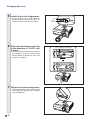
Changing the Lens
Info
• Before changing the lens, turn off the power of the projector and remove the power cord from the wall
outlet.
• Do not attempt to change the lens while the projector is mounted on the ceiling.
1
Remove the lens housing cover
by using the supplied lens housing cover removal tool to push
down on the groove on the lens
housing cover.
• Hold down the lens housing cover with
your hand to prevent it from flying out.
2
Slide the lens fastener catch tab
in the direction of “UNLOCK”
while holding the lens to prevent
it from falling out.
Lens fastener catch tab
• Slide the lens fastener catch tab until the
window located beside “LOCK” comes to
the top. Look inside the window to make
sure that the two grooves on the lens fastener ring are facing up.
Two grooves
Window
3
Remove the lens by pulling it
straight out.
4
Remove the protection cap from
the back of the new lens.
-9
Changing the Lens
5
Insert the lens into the projector.
• As you insert the lens, look inside the
window to make sure that the pin is inserted into the hole of the lens mount.
6
Slide the lens fastener catch tab
in the direction of “LOCK” until
it stops.
• Be careful not to rotate the lens fastener
ring too tight, as the lens fastener ring
will be difficult to loosen the next time
the lens is changed.
7
Replace the lens housing cover.
• If the lens housing cover is not secured
to the projector, you will not be able to
turn the power on.
-10
Pin
Lens
mount
Lens fastener catch tab
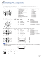
Connecting Pin Assignments
COMPUTER-RGB/COMPONENT INPUT 1, 2 and COMPUTER-RGB/COMPONENT OUTPUT Terminals:
15-pin mini D-sub female connector
COMPUTER-RGB Input/Output
11
15
1
6
5
10
1.
2.
3.
4.
5.
6.
7.
8.
9.
10.
11.
12.
13.
14.
15.
Component Input/Output
Video input (red)
Video input (green/sync on green)
Video input (blue)
Not connected
Not connected
Earth (red)
Earth (green/sync on green)
Earth (blue)
Not connected
GND
Not connected
Bi-directional data
Horizontal sync signal: TTL level
Vertical sync signal: TTL level
Data clock
1.
2.
3.
4.
5.
6.
7.
8.
9.
10.
11.
12.
13.
14.
15.
PR (CR)
Y
PB (CB)
Not connected
Not connected
Earth (PR)
Earth (Y)
Earth (PB)
Not connected
Not connected
Not connected
Not connected
Not connected
Not connected
Not connected
RS-232C Terminal: 9-pin mini DIN female connector
8
9
7
3
6
5
Pin No.
1
2
3
4
5
6
7
8
9
Signal
Name
I/O
RD
SD
Receive Data
Send Data
Input
Output
SG
Signal Ground
RS
CS
Request to Send
Clear to Send
Reference
Not connected
Connected to internal circuit
Connected to internal circuit
Not connected
Connected to internal circuit
Not connected
Connected to CS in internal circuit
Connected to RS in internal circuit
Not connected
4
2
1
RS-232C Terminal: 9-pin D-sub male connector of the DIN-D-sub RS-232C adaptor
1
6
Pin No.
1
2
3
4
5
6
7
8
9
5
9
Signal
Name
I/O
RD
SD
Receive Data
Send Data
Input
Output
SG
Signal Ground
RS
CS
Request to Send
Clear to Send
Reference
Not connected
Connected to internal circuit
Connected to internal circuit
Not connected
Connected to internal circuit
Not connected
Connected to CS in internal circuit
Connected to RS in internal circuit
Not connected
RS-232C Cable recommended connection: 9-pin D-sub female connector
5
9
Pin No.
1
2
3
4
5
6
7
8
9
1
6
Signal
CD
RD
SD
ER
SG
DR
RS
CS
CI
Pin No.
1
2
3
4
5
6
7
8
9
Signal
CD
RD
SD
ER
SG
DR
RS
CS
CI
Note
• Depending on the controlling device used, it may be necessary to connect Pin 4 and Pin 6 on the controlling
device (e.g. computer).
Projector
Pin No.
4
5
6
Computer
Pin No.
4
5
6
LAN Terminal : 8-pin RJ-45 modular connector
8...1
Pin No.
1
2
3
4
Signal
TX+
TX–
RX+
Pin No.
5
6
7
8
Signal
RX–
-11
Connecting Pin Assignments
DVI-D Input Terminal
Pin No.
-12
24
17
8
16
1
9
1
2
3
4
5
6
7
8
9
10
11
12
Signal
T.M.D.S. Data 2–
T.M.D.S. Data 2+
T.M.D.S. Data 2 Shield
Not connected
Not connected
DDC Clock
DDC Data
Not connected
T.M.D.S. Data 1–
T.M.D.S. Data 1+
T.M.D.S. Data 1 Shield
Not connected
Pin No.
13
14
15
16
17
18
19
20
21
22
23
24
Signal
Not connected
+5 V Power
Ground
Hot Plug Detect
T.M.D.S. Data 0–
T.M.D.S. Data 0+
T.M.D.S. Data 0 Shield
Not connected
Not connected
T.M.D.S. Clock Shield
T.M.D.S. Clock+
T.M.D.S. Clock–
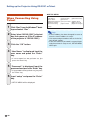
RS-232C Specifications and Commands
Computer control
A computer can be used to control the projector by connecting an RS-232C serial control cable (cross type,
commercially available) to the projector. (See page 27 of the projector’s operation manual for connection.)
Communication conditions
Set the serial port settings of the computer to match that of the table.
Signal format: Conforms to RS-232C standard.
Parity bit: None
Baud rate*: 9,600 bps / 38,400 bps / 115,200 bps
Stop bit: 1 bit
Data length: 8 bits
Flow control: None
*Set the projector’s baud rate to the same rate as used by the computer.
Basic format
Commands from the computer are sent in the following order: command, parameter, and return code. After
the projector processes the command from the computer, it sends a response code to the computer.
Command format
C1
C2
C3 C4
P1
P2
P3
Command 4-digit
Response code format
Normal response
O
K
Return code (0DH)
P4
Return code (0DH)
Parameter 4-digit
Problem response (communication error or incorrect command)
E
R
R
Return code (0DH)
Info
• When controlling the projector using RS-232C commands from a computer, wait for at least 40 seconds
after the power has been turned on, and then transmit the commands.
• After sending an input selection or picture adjustment command and then receiving an “OK” response
code, the projector may take some time to process the command. If a second command is sent while the
projector is still processing the first command, you may receive an “ERR” response code. If this happens,
try resending the second command.
• When more than one code is being sent, send each command only after the response code for the previous command from the projector is verified.
• “POWR????” “TABN _ _ _ 1” “TLPS _ _ _ 1” “TPOW _ _ _ 1” “TLPN _ _ _ 1” “TLTT _ _ _ 1” “TLTL _ _ _ 1”
“TNAM _ _ _ 1” “MNRD _ _ _ 1” “PJN0 _ _ _ 1”
− When the projector receives the special commands shown above:
* The on-screen display will not disappear.
* The “Auto Power Off” timer will not be reset.
− The special commands are available for applications that require continuous polling.
Note
• If an underbar (_) appears in the parameter column, enter a space.
• If an asterisk (*) appears in the parameter column, enter a value in the range indicated in brackets under
Control Contents.
*1 Serial No. Check command is used to read out the 12 digits of serial No..
*2 For setting the projector name, send the commands in the order of PJN1, PJN2 and PJN3.
*3 Parameters of CLR Temp settings are as follows.
CLR Temp
Parameter
CLR Temp
Parameter
5500K
_0 5 5
8500K
_0 8 5
6500K
_0 6 5
9300K
_0 9 3
7500K
_0 7 5
10500K
_1 0 5
*4 The adjustable range of “V-Pos” (V-Position) may vary depending on the screen resolution of the computer.
-13
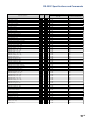
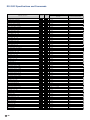
RS-232C Specifications and Commands
Commands
Example: When turning on the projector, make the following setting.
Computer
P
O
W
R
_
_
_
→
←
1
Projector
O
K
RETURN
CONTROL CONTENTS
COMMAND PARAMETER
Power ON
Power Off
Power On
Power Status
Projector Condition
P
P
P
T
O
O
O
A
W
W
W
B
R
R
R
N
_
_
?
_
_
_
?
_
_
_
?
_
0
1
?
1
OK or ERR
OK
1
0:Normal
1:Temp High
8:Lamp Life 5% or less
16:Lamp Burnt-out
32:Lamp Ignition Failure
Lamp Status
Lamp Power Status
Lamp Quantity
Lamp Usage Time (Hour)
Lamp Usage Time (Minute)
Lamp Life (Percentage)
Model Name Check
Model Name Check
Serial No. Check *1
Projector Name Setting 1 (First four characters) *2
Projector Name Setting 2 (Middle four characters) *2
Projector Name Setting 3 (Last four characters) *2
Projector Name Check
COMPUTER 1 (RGB1)
COMPUTER 2 (RGB2)
DVI (RGB3)
INPUT RGB Check
T
T
T
T
T
T
T
M
S
P
P
P
P
I
I
I
I
L
P
L
L
L
L
N
N
N
J
J
J
J
R
R
R
R
P
O
P
T
T
T
A
R
R
N
N
N
N
G
G
G
G
S
W
N
T
M
L
M
D
D
1
2
3
0
B
B
B
B
_
_
_
_
_
_
_
_
_
*
*
*
_
_
_
_
?
_
_
_
_
_
_
_
_
_
*
*
*
_
_
_
_
?
_
_
_
_
_
_
_
_
_
*
*
*
_
_
_
_
?
1
1
1
1
1
1
1
1
1
*
*
*
1
1
2
3
?
S-VIDEO (Video1)
VIDEO (Video2)
INPUT Video Check
INPUT Mode Check
INPUT Check
I
I
I
I
I
V
V
V
M
C
E
E
E
O
H
D
D
D
D
K
_
_
?
?
?
_
_
?
?
?
_
_
?
?
?
1
2
?
?
?
All Reset
Volume (0 - 60)
Volume up / down (– 10 - + 10)
Keystone (– 127 - + 127)
AV Mute Off
AV Mute On
Freeze Off
Freeze On
Eco+Quiet Mode : Off
Eco+Quiet Mode : On
Auto Sync Start
COMPUTER 1 Resize : Normal
COMPUTER 1 Resize : Stretch
COMPUTER 1 Resize : Dot By Dot
COMPUTER 1 Resize : Full
COMPUTER 1 Resize : Border
COMPUTER 2 Resize : Normal
COMPUTER 2 Resize : Stretch
COMPUTER 2 Resize : Dot By Dot
COMPUTER 2 Resize : Full
COMPUTER 2 Resize : Border
DVI Resize : Normal
DVI Resize : Stretch
DVI Resize : Dot By Dot
DVI Resize : Full
DVI Resize : Border
A
V
V
K
I
I
F
F
T
T
A
R
R
R
R
R
R
R
R
R
R
R
R
R
R
R
L
O
O
E
M
M
R
R
H
H
D
A
A
A
A
A
B
B
B
B
B
C
C
C
C
C
R
L
U
Y
B
B
E
E
M
M
J
S
S
S
S
S
S
S
S
S
S
S
S
S
S
S
E
A
D
S
K
K
Z
Z
D
D
S
R
R
R
R
R
R
R
R
R
R
R
R
R
R
R
_
_
_
_
_
_
_
_
_
_
_
_
_
_
_
_
_
_
_
_
_
_
_
_
_
_
_
_
*
*
_
_
_
_
_
_
_
_
_
_
_
_
_
_
_
_
_
_
_
_
_
_
_
*
*
*
_
_
_
_
_
_
_
_
_
_
_
_
_
_
_
_
_
_
_
_
_
_
1
*
*
*
0
1
0
1
0
1
1
1
2
3
5
6
1
2
3
5
6
1
2
3
5
6
0:Off, 1:On, 2:Retry, 3:Waiting, 4:Lamp Error
1:On, 2:Cooling
1
0 - 9999 (Integer)
0, 15, 30, 45
0% - 100% (Integer)
XGC465X / XGC435X
XG-C465X / XG-C435X
Serial No.
OK or ERR
OK or ERR
OK or ERR
Projector Name
OK or ERR
OK or ERR
OK or ERR
1:RGB1(COMPUTER1), 2:RGB2(COMPUTER2),
3:RGB3(DVI) or ERR
OK or ERR
OK or ERR
1:S-Video, 2:Video or ERR
1:RGB, 2:Video
1:COMPUTER1, 2:COMPUTER2, 3:DVI,
4:S-Video, 5:Video
OK or ERR
OK or ERR
OK or ERR
OK or ERR
OK or ERR
OK or ERR
OK or ERR
OK or ERR
OK or ERR
OK or ERR
OK or ERR
OK or ERR
OK or ERR
OK or ERR
OK or ERR
OK or ERR
OK or ERR
OK or ERR
OK or ERR
OK or ERR
OK or ERR
OK or ERR
OK or ERR
OK or ERR
OK or ERR
OK or ERR
-14
Standby mode
(or 40-second startup time)
OK
OK or ERR
0
0:Normal
1:Temp High
2:Fan Error
4:Cover Open
8:Lamp Life 5% or less
16:Lamp Burnt-out
32:Lamp Ignition Failure
64:Temp Abnormally High
0:Off, 4:Lamp Error
0:Standby
ERR
ERR
ERR
ERR
ERR
ERR
ERR
ERR
ERR
ERR
ERR
ERR
ERR
ERR
ERR
ERR
ERR
ERR
ERR
ERR
ERR
ERR
ERR
ERR
ERR
ERR
ERR
ERR
ERR
ERR
ERR
ERR
ERR
ERR
ERR
RS-232C Specifications and Commands
RETURN
CONTROL CONTENTS
S-Video Resize : Normal
S-Video Resize : Stretch
S-Video Resize : Border
S-Video Resize : Area Zoom
S-Video Resize : V-Stretch
Video Resize : Normal
Video Resize : Stretch
Video Resize : Border
Video Resize : Area Zoom
Video Resize : V-Stretch
COMPUTER 1 Adjustment Reset
COMPUTER 2 Adjustment Reset
DVI Adjustment Reset
S-VIDEO Adjustment Reset
VIDEO Adjustment Reset
COMPUTER 1 Picture Mode : Standard
COMPUTER 1 Picture Mode : Presentation
COMPUTER 1 Picture Mode : Movie
COMPUTER 1 Picture Mode : Game
COMPUTER 1 Picture Mode : sRGB
COMPUTER 1 Contrast (– 30 - + 30)
COMPUTER 1 Bright (– 30 - + 30)
COMPUTER 1 Color (– 30 - + 30)
COMPUTER 1 Tint (– 30 - + 30)
COMPUTER 1 Red (– 30 - 30)
COMPUTER 1 Blue (– 30 - + 30)
COMPUTER 1 Sharp (– 30 - + 30)
COMPUTER 1 CLR Temp *3
COMPUTER 1 Progressive : 2D
COMPUTER 1 Progressive : 3D
COMPUTER 1 Signal Type : Auto
COMPUTER 1 Signal Type : RGB
COMPUTER 1 Signal Type : Component
COMPUTER 2 Picture Mode : Standard
COMPUTER 2 Picture Mode : Presentation
COMPUTER 2 Picture Mode : Movie
COMPUTER 2 Picture Mode : Game
COMPUTER 2 Picture Mode : sRGB
COMPUTER 2 Contrast (– 30 - + 30)
COMPUTER 2 Bright (– 30 - + 30)
COMPUTER 2 Color (– 30 - + 30)
COMPUTER 2 Tint (– 30 - + 30)
COMPUTER 2 Red (– 30 - + 30)
COMPUTER 2 Blue (– 30 - + 30)
COMPUTER 2 Sharp (– 30 - + 30)
COMPUTER 2 CLR Temp *3
COMPUTER 2 Progressive : 2D
COMPUTER 2 Progressive : 3D
COMPUTER 2 Signal Type : Auto
COMPUTER 2 Signal Type : RGB
COMPUTER 2 Signal Type : Component
DVI Picture Mode : Standard
DVI Picture Mode : Presentation
DVI Picture Mode : Movie
DVI Picture Mode : Game
DVI Picture Mode : sRGB
DVI Contrast (– 30 - + 30)
DVI Bright (– 30 - + 30)
DVI Red (– 30 - + 30)
DVI Blue (– 30 - + 30)
DVI CLR Temp *3
COMMAND PARAMETER
R
R
R
R
R
R
R
R
R
R
R
R
R
V
V
R
R
R
R
R
R
R
R
R
R
R
R
R
R
R
I
I
I
R
R
R
R
R
R
R
R
R
R
R
R
R
R
R
I
I
I
R
R
R
R
R
R
R
R
R
R
A
A
A
A
A
B
B
B
B
B
A
B
C
A
B
A
A
A
A
A
A
A
A
A
A
A
A
A
A
A
A
A
A
B
B
B
B
B
B
B
B
B
B
B
B
B
B
B
B
B
B
C
C
C
C
C
C
C
C
C
C
S
S
S
S
S
S
S
S
S
S
R
R
R
R
R
P
P
P
P
P
P
B
C
T
R
B
S
C
I
I
S
S
S
P
P
P
P
P
P
B
C
T
R
B
S
C
I
I
S
S
S
P
P
P
P
P
P
B
R
B
C
V
V
V
V
V
V
V
V
V
V
E
E
E
E
E
S
S
S
S
S
I
R
O
I
D
E
H
T
P
P
I
I
I
S
S
S
S
S
I
R
O
I
D
E
H
T
P
P
I
I
I
S
S
S
S
S
I
R
D
E
T
_
_
_
_
_
_
_
_
_
_
_
_
_
_
_
_
_
_
_
_
_
_
_
_
_
_
_
_
_
_
_
_
_
_
_
_
_
_
_
_
_
_
_
_
_
_
_
_
_
_
_
_
_
_
_
_
_
_
_
_
_
_
_
_
_
_
_
_
_
_
_
_
_
_
_
_
_
_
_
_
_
*
*
*
*
*
*
*
*
_
_
_
_
_
_
_
_
_
_
*
*
*
*
*
*
*
*
_
_
_
_
_
_
_
_
_
_
*
*
*
*
*
_
_
_
1
1
_
_
_
1
1
_
_
_
_
_
1
1
1
1
1
*
*
*
*
*
*
*
*
_
_
_
_
_
1
1
1
1
1
*
*
*
*
*
*
*
*
_
_
_
_
_
1
1
1
1
1
*
*
*
*
*
1
2
3
0
1
1
2
3
0
1
1
1
1
1
1
0
1
2
3
4
*
*
*
*
*
*
*
*
0
1
0
1
2
0
1
2
3
4
*
*
*
*
*
*
*
*
0
1
0
1
2
0
1
2
3
4
*
*
*
*
*
Power ON
OK or ERR
OK or ERR
OK or ERR
OK or ERR
OK or ERR
OK or ERR
OK or ERR
OK or ERR
OK or ERR
OK or ERR
OK or ERR
OK or ERR
OK or ERR
OK or ERR
OK or ERR
OK or ERR
OK or ERR
OK or ERR
OK or ERR
OK or ERR
OK or ERR
OK or ERR
OK or ERR
OK or ERR
OK or ERR
OK or ERR
OK or ERR
OK or ERR
OK or ERR
OK or ERR
OK or ERR
OK or ERR
OK or ERR
OK or ERR
OK or ERR
OK or ERR
OK or ERR
OK or ERR
OK or ERR
OK or ERR
OK or ERR
OK or ERR
OK or ERR
OK or ERR
OK or ERR
OK or ERR
OK or ERR
OK or ERR
OK or ERR
OK or ERR
OK or ERR
OK or ERR
OK or ERR
OK or ERR
OK or ERR
OK or ERR
OK or ERR
OK or ERR
OK or ERR
OK or ERR
OK or ERR
Standby mode
(or 40-second startup time)
ERR
ERR
ERR
ERR
ERR
ERR
ERR
ERR
ERR
ERR
ERR
ERR
ERR
ERR
ERR
ERR
ERR
ERR
ERR
ERR
ERR
ERR
ERR
ERR
ERR
ERR
ERR
ERR
ERR
ERR
ERR
ERR
ERR
ERR
ERR
ERR
ERR
ERR
ERR
ERR
ERR
ERR
ERR
ERR
ERR
ERR
ERR
ERR
ERR
ERR
ERR
ERR
ERR
ERR
ERR
ERR
ERR
ERR
ERR
ERR
ERR
-15
RS-232C Specifications and Commands
RETURN
CONTROL CONTENTS
DVI Signal Type : D. PC RGB
DVI Signal Type : D. PC Comp.
DVI Signal Type : D. Video RGB
DVI Signal Type : D. Video Comp.
DVI Dynamic Range : Standard
DVI Dynamic Range : Enhanced
S-Video Picture Mode : Standard
S-Video Picture Mode : Presentation
S-Video Picture Mode : Movie
S-Video Picture Mode : Game
S-Video Contrast (– 30 - + 30)
S-Video Bright (– 30 - + 30)
S-Video Color (– 30 - + 30)
S-Video Tint (– 30 - + 30)
S-Video Red (– 30 - + 30)
S-Video Blue (– 30 - + 30)
S-Video Sharp (–30 - + 30)
S-Video CLR Temp *3
S-Video Progressive : 2D
S-Video Progressive : 3D
Video Picture Mode : Standard
Video Picture Mode : Presentation
Video Picture Mode : Movie
Video Picture Mode : Game
Video Contrast (– 30 - + 30)
Video Bright (– 30 - + 30)
Video Color (– 30 - + 30)
Video Tint (– 30 - + 30)
Video Red (– 30 - + 30)
Video Blue (– 30 - + 30)
Video Sharp (– 30 - + 30)
Video CLR Temp *3
Video Progressive : 2D
Video Progressive : 3D
Video System Selection : AUTO
Video System Selection : PAL
Video System Selection : SECAM
Video System Selection : NTSC4.43
Video System Selection : NTSC3.58
Video System Selection : PAL_M
Video System Selection : PAL_N
Video System Selection : PAL-60
Clock (– 30 - + 30)
Phase (– 15 - + 15)
H-Position (– 30 - + 30)
V-Position (– 30 - + 30) *4
Fine Sync Adjustment Reset
Auto Sync : Off
Auto Sync : On
RGB Horizontal Frequency Check
RGB Vertical Frequency Check
Image Shift (– 96 - + 96)
Auto Keystone : Off
Auto Keystone : On
OSD Display : Off
OSD Display : On
Background Selection : Logo
Background Selection : Blue
Background Selection : None
Auto Power Off : Off
Auto Power Off : On
System Sound : Off
System Sound : On
Auto Restart : Off
Auto Restart : On
-16
COMMAND PARAMETER
I
I
I
I
H
H
V
V
V
V
V
V
V
V
V
V
V
V
V
V
V
V
V
V
V
V
V
V
V
V
V
V
V
V
M
M
M
M
M
M
M
M
I
I
I
I
I
A
A
T
T
L
A
A
I
I
I
I
I
A
A
S
S
A
A
C
C
C
C
M
M
A
A
A
A
A
A
A
A
A
A
A
A
A
A
B
B
B
B
B
B
B
B
B
B
B
B
B
B
E
E
E
E
E
E
E
E
N
N
A
A
A
A
A
F
F
N
T
T
M
M
M
M
M
P
P
S
S
R
R
S
S
S
S
C
C
P
P
P
P
P
B
C
T
R
B
S
C
I
I
P
P
P
P
P
B
C
T
R
B
S
C
I
I
S
S
S
S
S
S
S
S
C
P
H
V
R
D
D
R
R
D
K
K
D
D
B
B
B
O
O
N
N
E
E
I
I
I
I
D
D
S
S
S
S
I
R
O
I
D
E
H
T
P
P
S
S
S
S
I
R
O
I
D
E
H
T
P
P
Y
Y
Y
Y
Y
Y
Y
Y
L
H
P
P
E
J
J
Q
Q
S
S
S
I
I
G
G
G
W
W
D
D
S
S
_
_
_
_
_
_
_
_
_
_
_
_
_
_
_
_
_
_
_
_
_
_
_
_
_
_
_
_
_
_
_
_
_
_
_
_
_
_
_
_
_
_
_
_
_
_
_
_
_
_
_
_
_
_
_
_
_
_
_
_
_
_
_
_
_
_
_
_
_
_
_
_
_
_
_
*
*
*
*
*
*
*
*
_
_
_
_
_
_
*
*
*
*
*
*
*
*
_
_
_
_
_
_
_
_
_
_
*
*
*
*
_
_
_
_
_
*
_
_
_
_
_
_
_
_
_
_
_
_
_
_
_
_
_
_
_
1
1
1
1
*
*
*
*
*
*
*
*
_
_
1
1
1
1
*
*
*
*
*
*
*
*
_
_
_
_
_
_
_
_
_
_
*
*
*
*
_
_
_
_
_
*
_
_
_
_
_
_
_
_
_
_
_
_
_
3
4
5
6
1
2
0
1
2
3
*
*
*
*
*
*
*
*
0
1
0
1
2
3
*
*
*
*
*
*
*
*
0
1
1
2
3
4
5
6
7
8
*
*
*
*
1
0
1
1
2
*
0
1
0
1
1
3
4
0
1
0
1
0
1
Power ON
OK or ERR
OK or ERR
OK or ERR
OK or ERR
OK or ERR
OK or ERR
OK or ERR
OK or ERR
OK or ERR
OK or ERR
OK or ERR
OK or ERR
OK or ERR
OK or ERR
OK or ERR
OK or ERR
OK or ERR
OK or ERR
OK or ERR
OK or ERR
OK or ERR
OK or ERR
OK or ERR
OK or ERR
OK or ERR
OK or ERR
OK or ERR
OK or ERR
OK or ERR
OK or ERR
OK or ERR
OK or ERR
OK or ERR
OK or ERR
OK or ERR
OK or ERR
OK or ERR
OK or ERR
OK or ERR
OK or ERR
OK or ERR
OK or ERR
OK or ERR
OK or ERR
OK or ERR
OK or ERR
OK or ERR
OK or ERR
OK or ERR
x10-1kHz (***.* or ERR)
Hz (*** or ERR)
OK or ERR
OK or ERR
OK or ERR
OK or ERR
OK or ERR
OK or ERR
OK or ERR
OK or ERR
OK or ERR
OK or ERR
OK or ERR
OK or ERR
OK or ERR
OK or ERR
Standby mode
(or 40-second startup time)
ERR
ERR
ERR
ERR
ERR
ERR
ERR
ERR
ERR
ERR
ERR
ERR
ERR
ERR
ERR
ERR
ERR
ERR
ERR
ERR
ERR
ERR
ERR
ERR
ERR
ERR
ERR
ERR
ERR
ERR
ERR
ERR
ERR
ERR
ERR
ERR
ERR
ERR
ERR
ERR
ERR
ERR
ERR
ERR
ERR
ERR
ERR
ERR
ERR
ERR
ERR
ERR
ERR
ERR
ERR
ERR
ERR
ERR
ERR
ERR
ERR
ERR
ERR
ERR
ERR
RS-232C Specifications and Commands
RETURN
CONTROL CONTENTS
Internal Speaker : Off
Internal Speaker : On
Audio Out : FAO
Audio Out : VAO
PRJ Mode : Reverse Off
PRJ Mode : Reverse On
PRJ Mode : Invert Off
PRJ Mode : Invert On
Fan Mode : Normal
Fan Mode : High
Monitor Out : Disable
Monitor Out : Enable
Language Selection : ENGLISH
Language Selection : DEUTSCH
Language Selection : ESPAÑOL
Language Selection : NEDERLANDS
Language Selection : FRANÇAIS
Language Selection : ITALIANO
Language Selection : SVENSKA
Language Selection :
Language Selection : PORTUGUÊS
Language Selection :
Language Selection :
Language Selection :
Language Selection :
Language Selection : polski
Language Selection : Türkçe
Lamp Timer Reset *5
COMMAND PARAMETER
A
A
A
A
I
I
I
I
H
H
M
M
M
M
M
M
M
M
M
M
M
M
M
M
M
M
M
L
S
S
O
O
M
M
M
M
L
L
O
O
E
E
E
E
E
E
E
E
E
E
E
E
E
E
E
P
P
P
U
U
R
R
I
I
M
M
U
U
L
L
L
L
L
L
L
L
L
L
L
L
L
L
L
R
K
K
T
T
E
E
N
N
D
D
T
T
A
A
A
A
A
A
A
A
A
A
A
A
A
A
A
E
_
_
_
_
_
_
_
_
_
_
_
_
_
_
_
_
_
_
_
_
_
_
_
_
_
_
_
0
_
_
_
_
_
_
_
_
_
_
_
_
_
_
_
_
_
_
_
_
_
_
_
_
_
_
_
0
_
_
_
_
_
_
_
_
_
_
_
_
_
_
_
_
_
_
_
_
_
1
1
1
1
1
1
0
0
1
1
2
0
1
0
1
0
1
0
1
1
2
3
4
5
6
7
8
9
0
1
2
3
4
5
1
Power ON
OK or ERR
OK or ERR
OK or ERR
OK or ERR
OK or ERR
OK or ERR
OK or ERR
OK or ERR
OK or ERR
OK or ERR
OK or ERR
OK or ERR
OK or ERR
OK or ERR
OK or ERR
OK or ERR
OK or ERR
OK or ERR
OK or ERR
OK or ERR
OK or ERR
OK or ERR
OK or ERR
OK or ERR
OK or ERR
OK or ERR
OK or ERR
ERR
Standby mode
(or 40-second startup time)
ERR
ERR
ERR
ERR
ERR
ERR
ERR
ERR
ERR
ERR
ERR
ERR
ERR
ERR
ERR
ERR
ERR
ERR
ERR
ERR
ERR
ERR
ERR
ERR
ERR
ERR
ERR
OK or ERR
*5 Lamp Timer Reset command is available only in standby mode.
PJLinkTM Compliant:
This product conforms with the PJLink standard Class 1 and all Class 1 commands are implemented.
This product confirms with the PJLink standard specification version 1.00.
For additional information, visit “http://pjlink.jbmia.or.jp/english/”.
-17
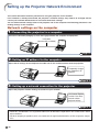
Setting up the Projector Network Environment
This section describes the basic procedure for using the projector via the network.
If the network is already constructed, the projector’s network settings may need to be changed. Please
consult your network administrator for assistance with these settings.
You can make network settings both on the projector and on the computer. The following procedure is for
making settings on the computer.
Network settings on the computer
1. Connecting the projector to a computer
Connect a LAN cable (Category 5, cross-over type) between the computer and projector.
LAN cable
(commercially available)
Page 19
2. Setting an IP address for the computer
Adjust the IP settings of the computer to enable one-to-one communications with the projector.
Temporarily change
the computer’s IP
address.
Pages 20, 21
3. Setting up a network connection for the projector
Adjust the projector network settings to conform to your network.
Use Internet Explorer
(version 5.0 or later)
to make various
projector settings.
Pages 22, 23
• Microsoft® and Windows® are registered trademarks of Microsoft Corporation in the United States and/or
other countries.
• All other company or product names are trademarks or registered trademarks of their respective companies.
-18
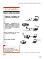
Setting up the Projector Network Environment
1. Connecting the Projector to a Computer
Establishing a one-to-one connection from the
projector to a computer. Using a LAN cable
(Category 5, cross-over type) you can configure the projector via the computer.
1
Disconnect the computer’s LAN
cable from the existing network.
A LAN cable being
connected to the network
2
Connect a LAN cable (a UTP
cable, Category 5, cross-over
type) to the projector’s LAN terminal and connect the other end
of the cable to the computer’s
LAN terminal.
LAN cable
(cross-over type, commercially available)
3
Plug the power cord into the AC
socket of the projector.
4
Turn on the computer.
ON
Info
Confirm that the LINK LED on the rear of the
projector illuminates. If the LINK LED does not
illuminate, check the following :
• The LAN cable is properly connected.
• The power switches of both the projector
and the computer are on.
This completes the connection. Now proceed to “2. Setting an IP Address for the Computer”.
-19
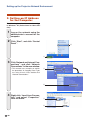
Setting up the Projector Network Environment
2. Setting an IP Address
for the Computer
The following describes how to make settings
in Windows® XP (Professional or Home Edition).
1
Log on the network using the
administrator’s account for the
computer.
2
Click “Start”, and click “Control
Panel”.
2
1
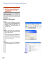
3
Click “Network and Internet Connections”, and click “Network
Connections” in the new window.
• This manual uses examples to explain
the operations in Category View. If you
are using Classic View, double-click
“Network Connections”.
1
2
4
Right-click “Local Area Connection” and select “Properties”
from the menu.
1
2
-20
Setting up the Projector Network Environment
5
Click “Internet Protocol (TCP/IP)”,
and click the “Properties” button.
1
2
6
Confirm or change an IP address
for the setup computer.
1 Confirm and note the current IP address, Subnet mask and Default
gateway.
Make sure to note the current IP address, Subnet mask and Default gateway as you will be required to reset
them later.
2 Set temporarily as follows :
IP address : 192.168.150.3
Subnet mask : 255.255.255.0
Default gateway : (Do not input any
values.)
Note
• The factory default settings for the projector
are as follows:
DHCP Client : Off
IP address : 192.168.150.2
Subnet mask : 255.255.255.0
Default gateway : 0.0.0.0
7
After setting, click the “OK” button, and then restart the computer.
After confirming or setting, proceed to “3. Setting up Network Connection for the Projector”.
-21
Setting up the Projector Network Environment
3. Setting up a Network
Connection for the
Projector
Settings for such items as the projector’s IP
address and subnet mask are compatible with
the existing network.
Set each item on the projector as follows. (See
page 53 of the projector’s operation manual
for setting.)
DHCP Client : Off
IP Address : 192.168.150.002
Subnet Mask : 255.255.255.000
1
Start Internet Explorer (version
5.0 or later) on the computer, and
enter “http://192.168.150.2/” in
“Address”, and then press the
“Enter” key.
2
If a user name and a password
have not yet been set, just click
the “OK” button.
• If a user name and a password have
been set, input the user name and the
password, and click the “OK” button.
• If the user name or password is entered
incorrectly three times, an error message will be displayed.
3
-22
When the screen as shown on
the right appears, click “TCP/IP”.
Setting up the Projector Network Environment
4
The TCP/IP setting screen appears, ready for network settings
for the projector.
Items
Setting example / Remarks
DHCP
Select “ON” or “OFF” to determine
Client
whether to use DHCP Client.
IP Address You can set this item when “DHCP
Client” is set to “OFF”.
Factory default setting: 192.168.150.2
Enter an IP address appropriate
for the network.
Subnet
You can set this item when “DHCP
Mask
Client” is set to “OFF”.
Factory default setting: 255.255.255.0
Set the subnet mask to the same
as that of the computer and
equipment on the network.
Default
You can set this item when “DHCP
Gateway
Client” is set to “OFF”.
Factory default setting: 0.0.0.0
* When not in use, set to “0.0.0.0”.
DNS
Factory default setting: 0.0.0.0
Server
* When not in use, set to “0.0.0.0”.
Note
• Confirm the existing network’s segment (IP
address group) to avoid setting an IP address that duplicates the IP addresses of
other network equipment or computers. If
“192.168.150.2” is not used in the network
having an IP address of “192.168.150.XXX”,
you don’t have to change the projector IP
address.
• For details about each setting, consult your
network administrator.
•
•
•
•
5
Click the “Apply” button.
6
The set values appear. Confirm
that the values are set properly,
and then click the “Confirm” button.
Close the browser.
This completes the network settings.
After setting items, wait for 10 seconds and then re-access.
Change the IP address of the setting computer back to its original address, which you have noted down in
Step 6-1 on page 21, and then connect the computer and the projector to the network.
-23
Controlling the Projector via LAN
After connecting the projector to your network, enter the projector IP address in “Address”
on Internet Explorer (version 5.0 or later) using a computer on the network to start a setup
screen that will enable control of the projector via the network.
Controlling the Projector
Using Internet Explorer
(Version 5.0 or later)
Complete connections to external equipment
before starting the operation. (See pages 2129 of the projector’s operation manual.)
Complete the AC cord connection. (See page
30 of the projector’s operation manual.)
Note
• When connecting the projector to the LAN, use
a LAN cable (Category 5). When connecting the
projector to a hub, use a straight-through cable.
1
Start Internet Explorer (version 5.0
or later) on the computer.
2
Enter “http://” followed by the
projector IP address set by the
procedure on page 23 followed
by “/” in “Address”, and then
press the “Enter” key.
• The factory default setting for the
projector : “DHCP Client” is “Off” and IP
address is “192.168.150.2”. If you did
not change the IP address in “3. Setting
up a Network Connection for the
Projector” (pages 22-23), enter “http://
192.168.150.2/”.
3
-24
A screen for controlling the projector appears, ready for performing various status conditions, control, and settings.
Controlling the Projector via LAN
Confirming the Projector
Status (Status)
Controlling the Projector
(Control)
On this screen, you can perform projector control. You can control the following items :
On this screen, you can confirm the projector
status. You can confirm the following items :
•
•
•
•
•
•
•
•
MAC Address
Power
Condition
Lamp Timer
Lamp Life
Input
Signal Info
Serial Number
Note
• If you click the “Refresh” button before the
screen is displayed completely, an error
message (“Server Busy Error”) will be displayed. Wait for a moment and then operate again.
• For details about each item, refer to the
projector’s operation manual.
•
•
•
•
Power
Input Select
Volume
AV Mute
Note
• If you click the “Refresh” button before the
screen is displayed completely, an error message (“Server Busy Error”) will be displayed.
Wait for a moment and then operate again.
• You cannot operate this page while the projector is warming up.
• While the projector is in standby mode, you
can only control “Power ON”.
• For details about each item, refer to the
projector’s operation manual.
-25
Controlling the Projector via LAN
Setting and Adjusting the
Projector (Settings & Adjustments)
Setting the Security
(Network – Security)
Example: “Picture” screen display for COMPUTER1
On these screens, you can make projector
settings or adjustments. You can set or adjust
the following items :
•
•
•
•
•
•
•
•
•
•
•
•
•
•
•
•
•
•
•
•
•
•
•
•
•
•
Picture Mode
CLR Temp
Progressive (Video)
Signal Type (Computer, DVI)
Dynamic Range (DVI)
Video System (Video)
Resolution Setting
Auto Sync
Resize
Auto Keystone
OSD Display
Background
Eco+Quiet Mode
Auto Power Off
System Sound
Menu Position
Auto Restart
Password
Internal Speaker
Audio Out
Projection Mode
Fan Mode
Monitor Out
RS-232C Speed
All Reset
Language
Note
• If you click the “Refresh” button before the
screen is displayed completely, an error message (“Server Busy Error”) will be displayed.
Wait for a moment and then operate again.
• You cannot operate this page while the projector is warming up.
• For details about each item, refer to the
projector’s operation manual.
-26
On this screen, you can make settings relating to security.
Items
Description
User Name Setting of user name for
security protection.
Password Setting of password for
security protection.
Accept IP It is possible to set up to three
Address
IP addresses allowing connection to the projector.
All IP
No limits are set to IP addresses
Addresses connecting to the projector.
From only For security improvement, only an
specific IP IP address set by “Address 1-3”
addresses can be connected to the projector.
Note
• User Name and Password can be up to 8
characters.
• You can input the characters below :
a-z, A-Z, 0-9, -, _
Controlling the Projector via LAN
Making General Settings
for the Network (Network -
Setting for Sending E-mail
when an Error Occurs
General)
(Mail – Originator Settings)
On this screen, you can make settings for
sending e-mail to report when the projector
has generated an error.
On this screen, you can make general settings
relating to the network.
Items
Projector
Name
Auto
Logout
Time
Data Port
Search
Port
Description
Setting the projector name.
Setting the time interval in
which the projector will be
automatically disconnected
from the network in units of a
minute (from 1 to 65535
minutes). If the set value is
made 0, the Auto Logout
function is disabled.
Setting the TCP port number
used when exchanging data
with the projector (from 1025 to
65535).
Setting the port number used
when searching for the
projector (from 1025 to 65535).
After clicking the “Apply” button, the set values appear. Confirm that the values are set
properly, and then click the “Confirm” button.
Note
• After setting items, wait for 10 seconds and
then re-access.
• Projector Name can be up to 12 characters.
• You can input the characters below :
A-Z, 0-9, -, _, (,), space
(When “a-z” are input, they are converted to
“A-Z” automatically.)
Items
SMTP
Server
Originator
E-mail
Address
Originator
Name
Setting example / Remarks
Setting an SMTP server
address for e-mail transmission.
e.g.1 : 192.168.150.253
e.g.2 : smtp123.sharp.co.jp
* When using a domain name,
make settings for the DNS
server.
Setting the projector’s e-mail
address. The e-mail address set
here becomes Originator E-mail
Address.
Setting the sender’s name.
The name set here appears in
the “Originator Name” column
of the body of the message.
Note
• SMTP Server, Originator E-mail Address and
Originator Name can be up to 64 characters.
• You can input the characters below:
SMTP Server and Originator E-mail Address :
a-z, A-Z, 0-9, !, #, $, %, &, *, +, -, /, =, ?, ^, {,
|, }, ~, _, ’, ., @, `
(You can input “@” only one time for “Originator E-mail Address”.)
Originator Name : a-z, A-Z, 0-9, -, _, (,), space
• If the settings of “3. Setting up a Network
Connection for the Projector” on pages 22
and 23 are incorrectly set, e-mail will not be
send.
-27
Controlling the Projector via LAN
Setting Error Items and
Destination Addresses to
which E-mail is to be Sent
when an Error Occurs
Setting Error Items and
the URL that are to be
Displayed when an Error
Occurs (Service & Support –
(Mail – Recipient Settings)
Access URL)
On this screen, you can input e-mail destinations to which error notification (error items)
e-mails are sent.
On this screen, you can make settings of the
URL and error items that are to be displayed
when the projector has generated an error.
Items
E-mail
Address
Description
Set addresses to which error
notification e-mail is sent. You
can set up to five addresses.
Error Mail Error e-mail is sent on the error
(Lamp, Temp, items checked in their check
Fan, Cover) boxes.
Test
Send test e-mail. This allows
you to confirm that the settings
for e-mail transmission are
properly set.
Note
• E-mail Address can be up to 64 characters.
• You can input the characters below :
a-z, A-Z, 0-9, !, #, $, %, &, *, +, -, /, =, ?, ^, {, |,
}, ~, _, ’, ., @, `
(You can input “@” only one time.)
• For details about error items, refer to the
projector’s operation manual.
-28
Items
Access
URL
Description
Set the URL that is to be
displayed when an error
occurs. You can set up to five
addresses.
Condition The URL is displayed when an
(Always, Lamp, error checked in their check
Temp, Fan, Cover) boxes occurs.
Test
The set URL site is testdisplayed. This allows you to
confirm that the URL site is
properly displayed.
Example of the display when an error occurs
Setting up the Projector Using RS-232C or Telnet
Connect the projector to a computer using RS-232C or Telnet, and open the SETUP MENU on
the computer to carry out various settings for the projector.
When Connecting Using
RS-232C
1
2
Launch general purpose terminal
emulator.
Input settings for the RS-232C port
of the terminal emulator as follows.
Baud Rate
Data Length
Parity Bit
Stop Bit
Flow Control
: 9600 bps*
: 8 bit
: None
: 1 bit
: None
* This is the factory default setting. If the value
of Baud Rate for the projector has been
changed, set Baud Rate here according to
the changed value on the projector.
3
Input “PJS11234” and press the “Enter” key.
4
“OK” is displayed. Input “PJS25678”
and press the “Enter” key within 10
seconds.
5
“User Name:” is displayed. Input the
user name and press the “Enter”
key.
7
Input “setup” and press the “Enter”
key.
• SETUP MENU will be displayed.
▼SETUP MENU
---------------------------------SETUP MENU-------------------------------[1]IP Address
[2]Subnet Mask
[3]Default Gateway
[4]User Name
[5]Password
[6]RS-232C Baud Rate [7]Projector Name [8]DHCP Client
[A]Advanced Setup
[D]Disconnect All
[V]View All Setting
[S]Save & Quit
[Q]Quit Unchanged
setup>
Note
• User name and password are not set in the factory default settings.
• If the user name or password is entered incorrectly three times, SETUP MENU will be quit.
• If a user name has not yet been set, just
press the “Enter” key.
6
“Password:” is displayed. Input the
password and press the “Enter” key.
• If a password has not yet been set, just press
the “Enter” key.
-29
Setting up the Projector Using RS-232C or Telnet
▼SETUP MENU
When Connecting Using
Telnet
1
Click “Start” from the Windows® desktop and select “Run”.
---------------------------------SETUP MENU-------------------------------[1]IP Address
[2]Subnet Mask
[3]Default Gateway
[4]User Name
[5]Password
[6]RS-232C Baud Rate [7]Projector Name [8]DHCP Client
[A]Advanced Setup
[D]Disconnect All
[V]View All Setting
[S]Save & Quit
[Q]Quit Unchanged
setup>
Note
2
Enter “telnet 192.168.150.2” in the text
box that opens up. (If the IP address
of the projector is 192.168.150.2.)
3
Click the “OK” button.
4
“User Name:” is displayed. Input the
user name and press the “Enter”
key.
• If a user name has not yet been set, just
press the “Enter” key.
5
“Password:” is displayed. Input the
password and press the “Enter” key.
• If a password has not yet been set, just press
the “Enter” key.
6
Input “setup” and press the “Enter”
key.
• SETUP MENU will be displayed.
-30
• If the IP address has been changed, be sure to
enter the new IP address in step 2.
• User name and password are not set in the factory default settings.
• If the user name or password is entered incorrectly three times in steps 4 or 5, SETUP MENU
will be quit.
Setting up the Projector Using RS-232C or Telnet
SETUP MENU
(Main Menu)
▼SETUP MENU
---------------------------------SETUP MENU-------------------------------[1]IP Address
[2]Subnet Mask
[3]Default Gateway
[4]User Name
[5]Password
[6]RS-232C Baud Rate [7]Projector Name [8]DHCP Client
[A]Advanced Setup
[D]Disconnect All
[V]View All Setting
[S]Save & Quit
[Q]Quit Unchanged
ADVANCED SETUP MENU
▼ADVANCED SETUP MENU
******************** ADVANCED SETUP MENU ***********************
[1]Auto Logout Time [2]Data Port
[5]Network Ping Test
[6]Accept IP Addr(1) [7]Accept IP Addr(2) [8]Accept IP Addr(3)
[9]Accept All IP Addr [0]Search Port
[!]Restore Default Setting
[Q]Return to Main Menu
setup>
[1]IP Address
IP address settings. (Page 34)
[2]Subnet Mask
Subnet mask settings. (Page 34)
[3]Default Gateway
Default gateway settings. (Page 34)
[4]User Name (Factory default setting : Not Required)
Setting of user name for security protection. (Page 34)
[5]Password (Factory default setting : Not Required)
Setting of password for security protection. (Page 35)
[6]RS-232C Baud Rate (Factory default setting :
9600 bps)
Baud rate settings for the RS-232C terminals. (Page
35)
[7]Projector Name
It is possible to assign a projector name. (Page 35)
[8]DHCP Client
DHCP Client settings. (Page 35)
[A]Advanced Setup
Enters ADVANCED SETUP MENU. (Page 36)
[D]Disconnect All
Disconnect all connections. (Page 36)
[V] View All Setting
Displays all setting values. (Page 32)
Can also be used with ADVANCED SETUP MENU.
[S] Save & Quit
Save set values and quit menu. (Page 33)
[Q]Quit Unchanged
Quit menu without saving setting values. (Page 33)
advanced>
[1]Auto Logout Time (Factory default setting : 5 minutes)
Setting of time until automatic disconnection of network connection. (Page 36)
[2]Data Port (Factory default setting : 10002)
Setting the TCP port number used when exchanging data. (Page 36)
[5]Network Ping Test
It is possible to confirm that a network connection
between the projector and a computer etc. is working normally. (Page 37)
[6]Accept IP Addr(1)
[7]Accept IP Addr(2)
[8]Accept IP Addr(3)
[9]Accept All IP Addr (Factory default setting : Accept All)
For improved security, it is possible to set up to three
IP addresses allowing connection to the projector.
Set IP addresses can be cancelled using [9] Accept
All IP Addr. (Page 37)
[0] Search Port (Factory default setting : 5006)
Setting the port number used when searching for
the projector. (Page 38)
[!] Restore Default Setting
Restores all setting values that can be set using the
menu to the default state. (Page 38)
[Q]Return to Main Menu
Return to the main SETUP MENU. (Page 38)
Note
• The factory default settings for the projector are
as follows:
DHCP Client : Off
IP address : 192.168.150.2
Subnet mask : 255.255.255.0
Default gateway : 0.0.0.0
-31
Setting up the Projector Using RS-232C or Telnet
Enter number or symbol of item to be selected on the SETUP MENU. When setting, input the
details to be set. Setting is carried out one item at a time, and saved at the end.
View Setting Detail List
Set Items
([V]View All Setting)
Example: When setting IP Address (change from
192.168.150.2 to 192.168.150.3)
▼SETUP MENU
▼SETUP MENU
---------------------------------SETUP MENU-------------------------------[1]IP Address
[2]Subnet Mask
[3]Default Gateway
[4]User Name
[5]Password
[6]RS-232C Baud Rate [7]Projector Name [8]DHCP Client
[A]Advanced Setup
[D]Disconnect All
[V]View All Setting
[S]Save & Quit
[Q]Quit Unchanged
setup>v
Model Name
: XX-XXXX
Projector Name
: XX-XXXX
MAC Address
: XX:XX:XX:XX:XX:XX
DHCP Client
: Disabled
IP Address
: 192.168.150.2
Subnet Mask
: 255.255.255.0
Default Gateway
: Not Used
RS-232 Baud Rate : 9600 bps
Password
: Not Required
**********(Advanced Status)**********
Data Port
: 10002
Accept IP Address : Accept All
Auto Logout Time : 5 minutes
Search Port
: 5006
1 Enter “v” and press the “Enter” key.
Display all setting values(*).
1
*
---------------------------------SETUP MENU-------------------------------[1]IP Address
[2]Subnet Mask
[3]Default Gateway
[4]User Name
[5]Password
[6]RS-232C Baud Rate [7]Projector Name [8]DHCP Client
[A]Advanced Setup
[D]Disconnect All
[V]View All Setting
[S]Save & Quit
[Q]Quit Unchanged
setup>1
IP Address
: 192.168.150.2
Please Enter
: 192.168.150.3
(change)
—> 192.168.150.3
---------------------------------SETUP MENU-------------------------------[1]IP Address
[2]Subnet Mask
[3]Default Gateway
[4]User Name
[5]Password
[6]RS-232C Baud Rate [7]Projector Name [8]DHCP Client
[A]Advanced Setup
[D]Disconnect All
[V]View All Setting
[S]Save & Quit
[Q]Quit Unchanged
1
*1
2
*2
setup>v
Model Name
: XX-XXXX
Projector Name
: XX-XXXX
MAC Address
: XX:XX:XX:XX:XX:XX
DHCP Client
: Disabled
IP Address
: 192.168.150.3
Subnet Mask
: 255.255.255.0
Default Gateway
: Not Used
RS-232C Baud Rate : 9600 bps
Password
: Not Required
**********(Advanced Status)**********
Data Port
: 10002
Accept IP Address : Accept All
Auto Logout Time : 5 minutes
Search Port
: 5006
3
*3
1 Enter “1” (number of item to be set), and press
the “Enter” key.
Display current IP address (*1).
2 Enter IP address to be set and press the “Enter” key.
Display IP address after change (*2).
3 Enter “v” and press the “Enter” key to verify
setting detail list.
IP address is being changed (*3).
Note
• Verification of setting detail list can be omitted.
• Setting details are not effective until they have
been saved. (Page 33)
• If an invalid number is entered, an error message
(“Parameter Error!”) will be displayed.
-32
Setting up the Projector Using RS-232C or Telnet
Save Settings and Quit
([S]Save & Quit)
Quit without Saving Settings ([Q]Quit Unchanged)
Save set values and quit menu.
Quit menu without saving setting values.
▼SETUP MENU
▼SETUP MENU
---------------------------------SETUP MENU-------------------------------[1]IP Address
[2]Subnet Mask
[3]Default Gateway
[4]User Name
[5]Password
[6]RS-232C Baud Rate [7]Projector Name [8]DHCP Client
[A]Advanced Setup
[D]Disconnect All
[V]View All Setting
[S]Save & Quit
[Q]Quit Unchanged
---------------------------------SETUP MENU-------------------------------[1]IP Address
[2]Subnet Mask [3]Default Gateway
[4]User Name
[5]Password
[6]RS-232C Baud Rate [7]Projector Name [8]DHCP Client
[A]Advanced Setup
[D]Disconnect All
[V]View All Setting
[S]Save & Quit
[Q]Quit Unchanged
setup>s
All Connection will be disconnect.
Continue(y/n)? y
Apply New setting...Done.
1 Enter “s” and press the “Enter” key.
2 Enter “y” and press the “Enter” key.
1
2
setup>q
Quit Without Saving(y/n)? y
Setting Unchanged.
1
2
1 Enter “q” and press the “Enter” key.
2 Enter “y” and press the “Enter” key.
-33
Setting up the Projector Using RS-232C or Telnet
The setting procedure for each item will be explained. For the basic procedure, please refer
to “Set Items” on page 32.
IP Address Setting
Default Gateway Setting
([1]IP Address)
([3]Default Gateway)
Setting of IP address.
Setting default gateway.
setup>1
IP Address
Please Enter
(change)
—>
1
:192.168.150.2
:192.168.150.3
192.168.150.3
2
*
1 Enter “1” and press the “Enter” key.
2 Enter numerical value to be set and press the
“Enter” key.
Display IP address after change (*).
1
2
*
1 Enter “3” and press the “Enter” key.
2 Enter numerical value to be set and press the
“Enter” key.
Display gateway address after change (*).
Note
Subnet Mask Setting
• If the values for IP Address, Subnet Mask or Gateway of the projector have been changed via Telnet,
the computer cannot be connected to the projector
depending on the computer’s network settings.
([2]Subnet Mask)
Setting subnet mask.
setup>2
Subnet Mask
Please Enter
(change)
—>
setup>3
note: “0.0.0.0” means “Using no default gateway.”
Gateway Address :0.0.0.0
Please Enter
:192.168.150.1
(change)
—> 192.168.150.1
1
:255.255.255.0
:255.0.0.0
255.0.0.0
2
*
1 Enter “2” and press the “Enter” key.
2 Enter numerical value to be set and press the
“Enter” key.
Display subnet mask after change (*).
User Name Setting
([4]User Name)
Carrying out security protection using user name.
setup>4
User Name
:
Please Enter
: XX-XXXX
(change)
—> XX-XXXX
1
2
*
1 Enter “4” and press the “Enter” key.
2 Enter user name and press the “Enter” key.
Display set user name (*).
Note
• User name can be up to 8 characters.
• You can input the characters below :
a-z, A-Z, 0-9, -, _
• In the default state, user name is not set.
-34
Setting up the Projector Using RS-232C or Telnet
Password Setting
Projector Name Setting
([5]Password)
([7]Projector Name)
Carrying out security protection using password.
It is possible to assign a projector name.
setup>5
Password
:
Please Enter
: sharppj
(change)
—> sharppj
1
2
*
1 Enter “5” and press the “Enter” key.
2 Enter password and press the “Enter” key.
Display set password (*).
2
*
Note
• Projector name can be up to 12 characters.
• You can input the characters below :
A-Z, 0-9, -, _, (,), space
(When “a-z” are input, they are converted to “A-Z”
automatically.)
• It is the same as the name which can be confirmed or set, using RS-232C commands “PJN0”,
“PJN1”, “PJN2” and “PJN3”.
• Password can be up to 8 characters.
• You can input the characters below :
a-z, A-Z, 0-9, -, _
• In the default state, the password is not set.
RS-232C Baud Rate Setting ([6]RS-232C Baud Rate)
DHCP Client Setting
Setting of baud rate for RS-232C terminals.
1
0 ... 9600 bps
1 ... 38400 bps
2 ... 115200 bps
Baud Rate Select[0-2] :2
RS-232C Baud Rate : 115200 bps
1
: XX-XXXX
: MY XX-XXXX
MY XX-XXXX
1 Enter “7” and press the “Enter” key.
2 Enter projector name.
Display set projector name (*).
Note
setup>6
setup>7
Projector Name
Please Enter
(change)
—>
([8]DHCP Client)
Setting DHCP Client to “Enable” or “Disable”.
2
*
1 Enter “6” and press the “Enter” key.
2 Select and enter the number 0, 1 or 2 and
press the “Enter” key.
Display set baud rate (*).
Note
• Set the projector’s baud rate to the same rate as
that used by the computer.
Example: When setting DHCP Client to “Enable”
setup>8
note: It sets DHCP Client.
0 ... Disable
1 ... Enable
DHCP Select[0-1] : 1
DHCP Client : Enabled
Success get data from DHCP server.
] : [XX:XX:XX:XX:XX:XX]
[MAC Address
] : [192.168.150.2]
[IP Address
] : [255.255.255.0]
[Subnet Mask
[Default Gateway ] : [0.0.0.0]
[DHCP IP Address] : [192.168.150.1]
1
2
*
1 Enter “8” and press the “Enter” key.
2 Enter “1” and press the “Enter” key.
Display the obtained values (*).
-35
Setting up the Projector Using RS-232C or Telnet
Disconnecting All Connections ([D]Disconnect All)
Setting Auto Logout Time
It is possible to disconnect all the TCP/IP connections currently recognized by the projector. Even if
the COM Redirect port is fixed in the Busy status
due to a problem, it is possible to force the Ready
status back by carrying out this disconnection.
If there is no input after a fixed time, the projector
automatically disconnects network connection using
the Auto Logout function. It is possible to set the time
until the projector is automatically disconnected in
units of a minute (from 1 to 65535 minutes).
setup>d
Disconnect All Connections(y/n)?y
Now Disconnecting...
1
2
1 Enter “d” and press the “Enter” key.
2 Enter “y” and press the “Enter” key.
(ADVANCED[1]Auto Logout Time)
advanced>1
Valid range
: 0 to 65535 (minute)
note: if you enter “0”, auto logout function will be disable.
Auto Logout Time : 5
Please Enter
:15
(change)
—> 15
1
2
*
1 Enter “1” and press the “Enter” key.
2 Enter numerical value and press the “Enter” key.
Display set numerical value (*).
Note
• If Disconnect All is performed, the connection to
the projector via network will be forcibly disconnected.
Note
• If the set value is made 0, the Auto Logout function is disabled.
• If an invalid number is entered, an error message
(“Parameter Error!”) will be displayed and the
screen returns to the ADVANCED SETUP MENU.
Entering ADVANCED
SETUP MENU
([A]Advanced Setup)
Data Port Setting
Enters ADVANCED SETUP MENU.
setup>a
******************** ADVANCED SETUP MENU ***********************
[1]Auto Logout Time [2]Data Port
[5]Network Ping Test
[6]Accept IP Addr(1) [7]Accept IP Addr(2) [8]Accept IP Addr(3)
[9]Accept All IP Addr [0]Search Port
[!]Restore Default Setting
[Q]Return to Main Menu
advanced>
1 Enter “a” and press the “Enter” key.
1
(ADVANCED[2]Data Port)
Setting of TCP port number. It is possible to set in
the range of 1025 to 65535.
advanced>2
Valid range
Data Port
Please Enter
(change)
1
:1025 to 65535
:10002
:10005
—> 10005
2
*
1 Enter “2” and press the “Enter” key.
2 Enter numerical value and press the “Enter” key.
Display set numerical value (*).
Note
• Set according to need. Normally, use with the factory default setting.
-36
Setting up the Projector Using RS-232C or Telnet
Carrying out Network Ping
Test
Setting of Accept IP Address (ADVANCED[6]Accept IP
(ADVANCED[5]Network Ping Test)
Addr(1) - [8]Accept IP Addr(3))
It is possible to confirm that a network connection
between the projector and a computer etc. is working normally.
It is possible to improve security of the projector by
allowing connection from only a prescribed IP address. It is possible to set up to three IP addresses
allowing connection to the projector.
advanced>5
Ping dest IP addr :192.168.150.1
Please Enter
:192.168.150.152
(change)
—> 192.168.150.152
32 bytes from 192.168.150.152: icmp_seq = 1, time = 0 ms
32 bytes from 192.168.150.152: icmp_seq = 2, time = 0 ms
32 bytes from 192.168.150.152: icmp_seq = 3, time = 0 ms
32 bytes from 192.168.150.152: icmp_seq = 4, time = 0 ms
1
2
*1
*2
1 Enter “5” and press the “Enter” key.
2 Enter IP address of device to be tested and
press the “Enter” key.
Display entered IP address (*1).
Display test result (*2).
Note
• If the “Enter” key is pressed without entering an
IP address, the Ping destination IP address used
previously is entered.
• If there is a fault with the connection, “Error: No
answer” is displayed after a 5 second retry. In this
case, please confirm the settings for the projector
and the computer, and contact your network administrator.
1
advanced>6
Accept IP Addr(1) : 0.0.0.0
Please Enter
: 192.168.150.152
(change)
—> 192.168.150.152
2
*
1 Enter “6”, “7” or “8” and press the “Enter” key.
2 Enter numerical value and press the “Enter” key.
Display set numerical value (*).
Note
• To invalidate the Accept IP Address being currently set, enter “0.0.0.0”.
• If there is one or more Accept IP Addr being set,
no connections are allowed from IP addresses
that are not yet set. They can be cancelled using
[9]Accept All IP Addr.
Accepting All IP Addresses
(ADVANCED[9]Accept All IP Addr)
Removes IP addresses set with “Accept IP Addr”.
advanced>9
Accept All IP Addresses(y/n)? y
1
2
1 Enter “9” and press the “Enter” key.
2 Enter “y” and press the “Enter” key.
Note
• At the point in time where “y” was entered, the
numerical values for Accept IP Addr(1)-(3) are
reset to “0.0.0.0”.
• If “n” is entered, setting is not altered.
-37
Setting up the Projector Using RS-232C or Telnet
Setting of Search Port
Return to Main Menu
(ADVANCED[0]Search Port)
(ADVANCED[Q]Return to Main Menu)
Sets the port number used when searching for the
projector from the network.
Returns to the main SETUP MENU.
1
advanced>0
Please Enter Port Number for Search from Computer.
Valid range
: 1025 to 65535
Search Port
: 5006
Please Enter
: 5004
(change)
—> 5004
2
*
advanced>q
---------------------------------SETUP MENU-------------------------------[1]IP Address
[2]Subnet Mask
[3]Default Gateway
[4]User Name
[5]Password
[6]RS-232C Baud Rate [7]Projector Name [8]DHCP Client
[A]Advanced Setup
[D]Disconnect All
[V]View All Setting
[S]Save & Quit
[Q]Quit Unchanged
setup>
1 Enter “0” and press the “Enter” key.
2 Enter numerical value and press the “Enter” key.
Display set numerical value (*).
Note
• Set according to need. Normally, use with the factory default setting.
Return to Default Settings
(ADVANCED[!]Restore Default
Setting)
Returns all menu setting values to the default state.
advanced>!
Restore All Setting to Default(y/n)? y
— User Setting Initialized —
1
2
1 Enter “!” and press the “Enter” key.
2 Enter “y” and press the “Enter” key.
Note
• If the values for IP Address, Subnet Mask or Gateway of the projector have been returned to the
default settings via Telnet, the computer cannot
be connected to the projector depending on the
computer’s network settings.
-38
1 Enter “q” and press the “Enter” key.
Returns to the SETUP MENU.
1
Resetting the Lamp Timer of the Projector via LAN
When the projector is connected to a network, you can use HyperTerminal or a similar communications program to send a command to reset the lamp timer. The example below uses
Windows® XP as the operating system.
1
Click “Start” – “All Programs” –
“Accessories” – “Communications” – “HyperTerminal”.
• If you do not have HyperTerminal installed, see the operation manual of your
computer.
• Depending on the settings of your computer, you may be required to enter your
area code and other details. Enter the
information as required.
2
Enter a name in the “Name” field,
and click “OK”.
3
If you are required to enter the
area code, enter it in the “Area
code” field. From the “Connect
using” drop-down menu, select
“TCP/IP (Winsock)”, and click
“OK”.
4
Select
“TCP/IP (Winsock)”
Enter the IP address of the projector in the “Host address” field
(see “TCP/IP” on the “Network”
menu of the projector), and enter the data port of the projector
in the “Port number” field
(“10002” is the factory default
setting), and click “OK”.
-39
Resetting the Lamp Timer of the Projector via LAN
5
Click “Properties” on the “File”
menu.
6
Click the “Settings” tab, and
then click “ASCII Setup”.
7
Select the check boxes next to
“Send line ends with line feeds”,
“Echo typed characters locally”,
and “Append line feeds to incoming line ends”, and click
“OK”.
• The LAMPRESET Properties window
appears, click “OK”.
8
If a user name and/or password
is set for the projector, enter the
user name and password.
9
Send the lamp reset command
“LPRE0001”.
• This command can only be sent when
the projector is in standby mode.
• When “OK” is received, this indicates
that the lamp was successfully reset.
10
-40
Close HyperTerminal.
Troubleshooting
Communication cannot be established with the projector
When connecting the projector using serial-connection
\ Check that the RS-232C terminal of the projector and a computer or the commercially
available controller are connected correctly.
\ Check that the RS-232C cable is a cross-over cable.
\ Check that the RS-232C port setting for the projector corresponds to the setting for the
computer or the commercially available controller.
When connecting the projector to a computer using network (LAN)connection
\ Check that the cable’s connector is firmly inserted in the LAN terminal of the projector.
\ Check that the cable is firmly inserted into a LAN port for a computer or a network device
such as a hub.
\ Check that the LAN cable is a Category 5 cable.
\ Check that the LAN cable is a cross-over cable when connecting the projector to a computer
directly.
\ Check that the LAN cable is a straight-through cable when connecting the projector with a
network device such as a hub.
\ Check that the power supply is turned on for the network device such as a hub between the
projector and a computer.
Check the network settings for the computer and the projector
\ Check the following network settings for the projector.
• IP Address
Check that the IP address for the projector is not duplicated on the network.
• Subnet Mask
When the gateway setting for the projector is “0.0.0.0” (Not Used), or the gateway setting for
the projector and the default gateway setting for the computer are the same:
• The subnet masks for the projector and the computer should be the same.
• The IP address parts shown by the subnet mask for the projector and the computer should
be the same.
(Example)
When the IP address is “192.168.150.2” and the subnet mask is “255.255.255.0” for the
projector, the IP address for the computer should be “192.168.150.X” (X=3-254) and the
subnet mask should be “255.255.255.0”.
• Gateway
When the gateway setting for the projector is “0.0.0.0” (Not Used), or the gateway setting for
the projector and the default gateway setting for the computer are the same:
• The subnets for the projector and the computer should be the same.
• The IP address parts shown by the subnet mask for the projector and the computer should
be the same.
(Example)
When the IP address is “192.168.150.2” and the subnet mask is “255.255.255.0” for the
projector, the IP address for the computer should be “192.168.150.X” (X=3-254) and the
subnet mask should be “255.255.255.0”.
Note
• The factory default settings for the projector are as follows:
DHCP Client : Off
IP address : 192.168.150.2
Subnet mask : 255.255.255.0
Gateway address : 0.0.0.0 (Not Used)
• For network settings for the projector, refer to page 22.
-41
Troubleshooting
\ Take the following steps for checking the network settings for the computer.
1. Open a command prompt (MS-DOS Prompt).
• In the case of Windows® 98 or 98SE: click “START” ➔ “Programs” ➔ “MS-DOS Prompt” in
order.
• In the case of Windows® Me: click “START” ➔ “Programs” ➔ “Accessories” ➔ “MS-DOS
Prompt” in order.
• In the case of Windows® 2000: click “START” ➔ “Programs” ➔ “Accessories” ➔ “Command
Prompt” in order.
• In the case of Windows® XP: click “START” ➔ “All Programs” ➔ “Accessories” ➔ “Command
Prompt” in order.
2. After launching the command prompt (MS-DOS Prompt), enter the command “ipconfig”,
and press the “Enter” key.
Note
• Communication may not be established even after carrying out the network settings
for the computer. In such cases, restart your computer.
C:\>ipconfig
Note
• Usage examples of ipconfig
C:\>ipconfig /? displays how to use “ipconfig.exe”.
C:\>ipconfig
displays the set IP address, subnet mask and default gateway.
C:\>ipconfig /all displays all the setting information related to TCP/IP.
3. To return to the Windows® screen, enter “exit” and press the “Enter” key.
-42
Troubleshooting
\ Check if the “TCP/IP” protocol is operating correctly using the “PING” command. Also, check
if an IP address is set.
1. Open a command prompt (MS-DOS Prompt).
• In the case of Windows® 98 or 98SE: click “START” ➔ “Programs” ➔ “MS-DOS Prompt” in
order.
• In the case of Windows® Me: click “START” ➔ “Programs” ➔ “Accessories” ➔ “MS-DOS
Prompt” in order.
• In the case of Windows® 2000: click “START” ➔ “Programs” ➔ “Accessories” ➔ “Command
Prompt” in order.
• In the case of Windows® XP: click “START” ➔ “All Programs” ➔ “Accessories” ➔ “Command
Prompt” in order.
2. After launching the command prompt (MS-DOS Prompt) enter a command “PING”.
Entry example C:\>Ping XXX.XXX.XXX.XXX
“XXX.XXX.XXX.XXX” should be entered with an IP address to be connected to, such as
the projector.
3. When connecting normally, the display will be as follows.
(The screen may be slightly different depending on the OS type).
<Example> when the IP address connected to is “192.168.150.2”
4. When a command cannot be sent, “Request time out” will be displayed.
Check the network setting again.
If communication can still not be established properly, contact your network administrator.
5. To return to the Windows® screen, enter “exit” and then press the “Enter” key.
A connection cannot be made because you have forgotten your user name or your password.
\ Initialize the settings. (See page 54 of the projector’s operation manual.)
\ After the initialization, carry out setting again.
-43
Dimensions
Units: inches (mm)
Side View
/4 (6)
Rear View
Side View
17
/64
(6.5)
11 1/64 (279.5)
1
Top View
12 27/32 (326)
31
3 /64 (76.5)
4 (101.5)
63
1
/64
(25)
Front View
1 /32
(50)
3 31/64 (88.5)
2 15/16
(74.5)
5 53/64 (148)
5 53/64 (148)
2 61/64
(75)
2 29/32
1 5/64
(27.25) (73.5)
-44
37
10 /64 (268.5)
9 /32 (235.5)
9
5 25/32 (146.5)
Bottom View
Dimensions
Projector and Lens Dimensions
[When AN-C12MZ is installed]
Unit : inches (mm)
107
15 21/64 - 15 13/32 (389 - 391)
[When AN-C18MZ is installed]
Unit : inches (mm)
67.5
12 3/32 - 12 11/64 (307 - 309)
[When AN-C27MZ is installed]
Unit : inches (mm)
80
13 7/16 - 13 5/8 (341 - 346)
[When AN-C41MZ is installed]
Unit : inches (mm)
80
13 19/32 - 13 3/4 (345 - 349)
-45