1
TIPS S.R.L.
MASTER-DESIGN VER. 17.11.00
USER MANUAL | MASTER-DESIGN VER. 17.11.00
USER MANUAL
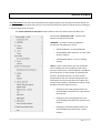
INTRODUCTION ................................................................................................................................................. 4
CREATES YOUR PROJECT USING TUTOR............................................................................................................ 5
PRICE LIST .......................................................................................................................................................... 8
MENU BAR....................................................................................................................................................... 12
SKIN AND MOUSE FUNCTIONS ........................................................................................................................ 19
WHAT IS TOOL-PAD ......................................................................................................................................... 37
ARTICLE MENU ................................................................................................................................................ 41
WALL SETTINGS WINDOW............................................................................................................................... 46
FINISHES WINDOW.......................................................................................................................................... 50
VARIANTS WINDOW........................................................................................................................................ 55
QUOTATION..................................................................................................................................................... 56
BASIC LIST WINDOW........................................................................................................................................ 69
VARIANTS......................................................................................................................................................... 80
EDIT ARTICLE PAGE.......................................................................................................................................... 82
VIRTUAL 3D.................................................................................................................................................... 106
TIPS-UPGRADE............................................................................................................................................... 116
CONCLUSION ................................................................................................................................................. 117
2|P age
3|P age
INTRODUCTION
Thank you for using Master-Design software.
This manual applies to modules:
•
Plan Lite/Pro (database personalizzato,progettazione, preventivazione, produzione, rendering,
virtual, CAD/CAM,…);
•
Art Lite/Pro (custom database, design, preventivation, rendering, virtual);
•
Art-Shop Lite/Std/Pro (generic database + custom, design, preventivation, rendering, virtual);
•
Art-Shop X-Lite (design with some limitations) FREEWARE.
This manual was written using Art-Shop PRO module. This module will be used in furniture stores or in
private sectors, it contains an archive of standard elements like:
Kitchens
Rooms
Bedrooms
Living rooms
Bathrooms
Modulars
Offices
Shops
Master-Design allow to realize the own furniture solution easily and in few time. The tutor integrated on
the program guides the user step by step in the creation of the own project and makes it simple to use.
There are a lot of new functions: new interface, Insertion of items by dragging, guide for the placement of
articles, new articles, integration with BLENDER, integration with GIMP.
There are different ways of viewing of the project (2D Front, 2D Plant, 2D front of all walls/projections, 3D
from any angle, Virtual 3D, etc..).
User also can choose the interface that prefer among the available “Skins” : Standard, Simple, CAD, Mini.
Master-Design
also
allow
the
importation
of
a
project
from
another
CAD
(DWG/DXF/EMF/WMF/BMP/JPG/GIF/VDF/WMF), importation of Master-Design Objects (objects from the
same family of products (for example Art distribuited by the manufacturer), or drawing directly in the
project. Master-Design also features the new module Master-Design CAD: CAD 2D/3D .
The free module Master-Design’s Art-Shop X-Lite has many limitations compared to the other paying
modules, but some features, like for example high resolution renderings, can be activated with a small
contribution following easy instructions that are shown selecting the same function at the apposite menu.
For example to do rendering is enough open Virtual 3D, using the menu and choose the rendering that the
user prefer .
To know all the features we recommend to go to the comparative table of features on the site www.tips.it.
If you need assistance and/or training you can contact our technician using the Skype phone service
www.skype.com calling the user www.master-design.it This service, provided for the users that aren’t
TIPS s.r.l. customers, has a cost per minut that will be request before starting advice. For this reason before
calling
is
recommended
to
control
to
have
credit
on
your
Skype
account.
4|P age
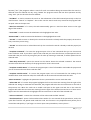
CREATES YOUR PROJECT USING TUTOR
- The Master-Design’s Tutor guide you through 10 easy
steps for the creation of your project. After the starting
of the program you can start to use
Master-Design clicking on “…start >>”.
- Then the tutor will show you all the possible choices;
the buttons where is highlighted the description of the
step are clickable, the other steps will be activated later
using the tutor. If the icon numbered on the left of the
choice is highlighted in blue means that the step is in
progress.
To start a new project, click on the button “New
project”, instead if you want to load an old project, click
on “Load project”
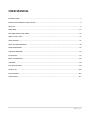
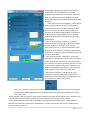
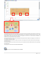
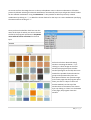
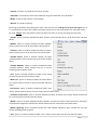
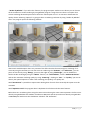
- After choosing “New project”, Master Design proposes
a choice window
about the creation of the
environment’s walls to furnish. As can be seen in the
picture below, the creation of the environment is fully
customizable and intuitive.
5|P age
- After the choice of the walls, the tutor asks to choose
the type of furniture to include in the project.
There are 6 types of furniture:
Kitchens
Brickwork Kitchens
Modulars (Rooms,Bedrooms,Living rooms)
Offices
Bathrooms
Shops
Then the tutor proposes finishes choice.
For each layer you can change the finish just clicking on its
name, on finish preview or on finish description.
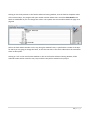
-After choosing the
finishes, the tutor
will activate the
other steps of its
own menu and will
also shows the price
list of the inserted
articles for the type
of furniture chosen.
6|P age
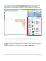
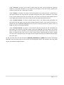
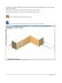
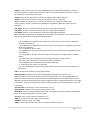
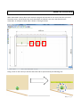
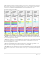
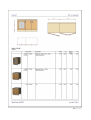
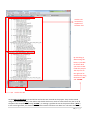
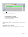
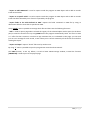
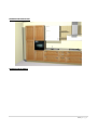
On the left we have the list of the articles divided in groups , instead on the right, once you have chosen
the group of articles, will appear the list of the inserted articles belonging to the group selected.
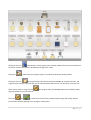
Clicking on the single article or dragging it on the work plan, it will be included as you can see in the next
picture:
You can insert other articles of other types of furniture clicking “Choose model”.
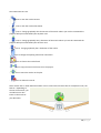
- Of each article in addition to the preview image there is also the code list, the description and the
measures in millimeters.
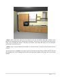
- Using the “Virtual 3D” icon you can view the project in 3D, moving on it and interacting with the articles
for example open/close doors. On Art-Shop X-Lite there is “mini Virtual 3D” (self limited in size and in other
functions).
- When you are satisfied of your own project, you can save it clicking on “Save project”.
7|P age
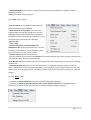
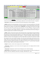
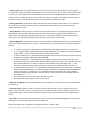
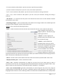
PRICE LIST
MASTER-DESIGN Price List
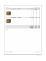
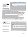
In the previous pages we have briefly summarized
the Master Design’s price list, now we are going to
handle the argument more in detail explaining all
the features that offers. Initially are displayed just
the available types of furnitures, that can vary list to
list. When you choose the type of furniture, the list
will activate all the tutor’s step and will display on
the left frame of the page the list of the articles
divided in group. (the exact function of the steps
will be explained on the next pages) After choosing
a group, on the right frame will appear all the list’s
articles for that types of furnitures; for each article
we have the preview image on size 100X100 pixel,
the code list and the description with the relative
sizes in millimeters. When the types of articles that
are in sequence are equal or they differ just in the
measures or in the code list, for a matter of order
and clarity, they are grouped under only an image
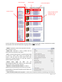
list for distinguished them. Using the page of “Edit Article” (it will be explained better later) you can
activate or disactivate this option based to the customer choice.
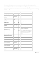
8|P age
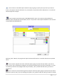
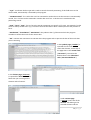
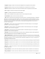
Article Image
Article Groups
Article Code
Article Description
Group of same article
typology under a
common image
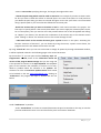
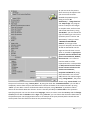
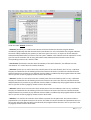
On the top of the price list (just above the tutor) there is “Tools” menù that contains commands to modify
the insertion of the articles. Below we are going to illustrate all commands :
-“UNDO” command, undo the last operation that was
done whatever it was.
-“Delete last” command is used to delete the last
article that was inserted in the project.
-“Find” is used to find characters in the description field
of each list’s article. After search, the program will
create a new list with all article which have been
marched. By double-clicking on a new list’s article, it
will be inserted in the project.
-“Attach
from
right
to
left”
can
be
attivated/disattivated and is used to insert articles from
right to left since the previous element.
-“Attach to a vertex the next element” is used to
disable the auto positioning of the article so you have
the possibility to choose by using the mouse where you
want to attach it.
- “Insert the next element in a free point” is used to have complete freedom of positioning of all elements.
9|P age
-“Edit not Insert” is used to edit the article without adding it in the project.
-“Reset the origin” , as the name suggests, it is used to reset the coordinates x,y,z and put the cursor on
the origin.
-“To the right of the wall” is used to put the coordinates and the cursor at the extreme right of the wall
that is used.
-“Disable Position Check” is used to disable Position Check. The Position Check controls where you put the
article and force the article to observe its size. With Position Check disabled, the elements can be put
everywhere inside the project and their size will not be respected.
- Using the menù “X”,”Y”,”Z” you can choose the coordinates of the respective and move the cursor on x,y
and z.
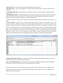
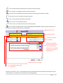
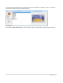
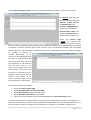
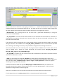
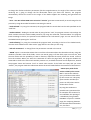
- “Classic insertion” is used to open a summary table where you can load the list’s elements. Also in this
case you can insert characters to search on the description field of each list’s article and at the last the
program will create a new list of all elements which have been marched. By clicking on an element of this
new list, it will be inserted on the summary table. If instead the article code is inserted directly on the field
“Cod.”, the article which has that code will be inserted on the list and all the fields of his row will be filled.
When all the articles that you need are on the list, clicking on “OK”, they will be loaded in the project.
Clicking on “Clean”, the list of the command “Classic insertion” will be cleaned and using the button
“Abort” the list will be closed. The list explained on “Classic insertion” is shown in the figure below.
-“Active Search Articles For Code” is used to activate the search (using the appropriate bar on the top of
the price list) of articles also by using the code list.
-When “No Group on price-list” is activated, all the price list articles will have the own preview image on
the price list so all the articles that were under an image will be divided.
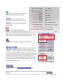
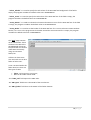
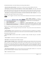
On our price list there is also a section where you can set the cursor coordinates (X,Y,Z) directly and by
using the respective icons you can: open and close the project menu, reset the cursor coordinates and
delete the last inserted article.
10 | P a g e
Cells to change the
coordinates
But to reset the
coordinates
Button to delete the last
inserted articles
Button to open and
close the project menu
Cell to search the
articles
When you use articles that belong to different types of
furniture, on the window like that in figure, the program will
create a list (Italian list) with all types of furniture used until
then.
11 | P a g e
MENU BAR
On the top of the Master Design window, there is the Menu Bar where all the operations and all commands
that the user can applies at the project are divided for categories.
Below there are all the functions provided by the program for each menu.
The possible operations by using “File” are:
- open a new project, save a project that you are using specifying a directory, or load an already started.
When you want to load a project already started you can choose to: load more projects, choose if the
loaded project must be added to the current project or must replace it, or if you want to do an Auto
BACKUP to reload a project if your PC has crashed (the software creates a temporary file to don’t lose the
job) . When you register a project, it will be registered under the specified directory with the formats: .sim,
.SCE e .EMF. When you want to load a project, the extension request is just .sim.
12 | P a g e
- use “Save a project for each environment” to save on a specify directory a general file (.sim, .EMF, and
.SCE formats) and many file as much as environments that are defined on the project (just in .sim and .EMF
formats) ;
- activate “Ownerships” to view in another window all the informations about Master-Design, keymachine,
activationkey etc...;
- “Clear the project” if you want to delete all the
articles inside the project;
- send project by mail with the relative function;
- activate print options: you can print the projection
that you are viewing watching the preview or not
and you can print for Plotter;
- export the project in DWG, DXF, VDF, EMF, WMF,
BMP and JPG formats;
- “Export Virtual 3D Viewer” to export the project in
V3D format that can be opened by MASTERDESIGN_V3D_Viewer (MASTER-DESIGN_V3D_Viewer
is a free 3D viewer like Virtual 3D);
- exit to Master-Design program.
By using “Tools” menu is possible (some of the discussed functions aren’t explained on this chapter but are
explained on their dedicated chapter):
- cancel the last performed operation;
- cancel the last inserted article;
- do a multi selection of elements or components;
- measure the distance between 2 points;
- choose the unit measurement;
- activate “Set Camera” to view in plant the camera icon and using set window that opens automatically
(image) to change the camera lens (by free free positioning or specifing the coordinates) and the amplitude
of the line of sight. Changing camera coordinates, the icon in the project will move automatically and that
makes easier under stand where it will point when you activate functions like Virtual 3D;
13 | P a g e
- use “Set lights” to open a
window with all light options; by
using this window, you can set
the intensity of the light, of the
environment or add other light
source just checking the number
and specifying the type. Other
possible operations are the
choise of position (by setting
coordinates or by freehand) and the power of the light expressed in Watt. Obviously depending on the
choice of the light, the effect inside Virtual 3D/rendering will be different;
- using “Photo Machine” to view the camera on the plant view;
- under “PROJECTIONS/WALLS” to open the wall menu (explained on “Wall Settings Window” chapter), or
set the complete view of walls on Virtual. Is also possible to move the considered wall’s articles to the ends
of the wall, to the center or to the ends minus an input value;
- using “Set Environment” I can define new
environments or activate/disactivate existing
environments by using a window like the one
shown
on
the left;
- open the price list;
- view the inserted elements basic list, to view the components of
the inserted articles. The view can be shown by a tree
representation or by a grid.
- open the furniture window;
- elaborate the inserted articles quotation;
-find articles by using the same search method of command “Find”
reported on the “Tools” menu;
14 | P a g e
- edit selected article;
- activate SNAP options menu;
- set Draw-Ref: Draw-Ref are automatic signs that are useful to mark the project elements and they are
reported on the project and on the quotation. This signs simplify the reading of the quotation and of the
project;
- open the Master-Design calculator which allow to do
basic mathematical operations just writing in the
function to calculate; is also possible by using MasterDesign calculator, writing in a value in millimetters, to
calculate automatically its value in centimeters and in
inches. On the left there are some examples of
operations by using our;
- copy the image of the project on the ClipBoard;
- use “List supplying” to open a page which contains a
list of all inserted articles and their suppliers, codes,
descriptions, prices and articles’ dimensions.
In “View” there are :
- the choice of the skins that are: Standard, Simple, Cad
e Mini (i twill be explained better on the chapter about skins);
- the possibility to hide the clone elements: the clone elements are the elements that are generated from a
father article and they inherit its all features. The clone elements are affected by father article changes,
whatever happens to the father, happens to the
clones;
- open the ruler with the possibilità to rotate it;
- redraw all article inserted in the project;
-choose the detail view. If is set to 1, the articles
datails will be displayed till their internal structure.
-set AutoZoom; setting autozoom the view will
place always automatically to frame all the inserted
articles.
Using “Draw” menu you can:
- activate all the functions about the importation and the modify of the pieces by using CAD program. In
the case of change and creation, the CAD program will be automatically open and in particular for the
modify, the project that you are using will be imported inside the CAD;
15 | P a g e
- activate all the functions about the importation and the modify of the pieces by using an external CAD
program. Activating this function, the program will open the CAD that is specified under the “?” menu
under the voice “Preferences”.
- choose if you want to draw directly inside the project or not; when this function is active you can draw all
the geometric drawings by freehand or directly inside the project. Instead if this function is off, for every
type of drawing will be opened a window where you have to specify the values of all features and positions.
- draw 2D objects: lines, polylines, arcs etc… (they will be illustrated more in detail in the skin paragraph).
With the insertion of a 2D
drawing, will be opened a
window where you can
choose the type of insertion
(absolute, relative, polar,
polar with relative angle or
specifying the direction) and
depending on the choice, in
addition to drawing by
freehand, will be requested
some parameters (that can also not be included) to be more accurate when you insert the figure;
- draw 3D objects: parallelepipeds, cylinders, spheres, etc... (they will be illustrated more in detail in the
skin paragraph). When you active the function to draw a 3D object, in addition to open the insertion
window as in the case of 2D objects, the program will open a window that request an obligatory input of
parameters and the choice of the layer of the object that you are going to draw. The input of parameters is
necessary to make accurate the representation of the drawing inside the project. To terminate the
insertion is necessary to push right button of mouse device;
- import and export Master-Design
objects: when you choose to import
objects the program will open a
window to choose the selection path
of the file to import that must be on
.MDOBJ extension. Instead when
you choose to export a MasterDesign object, you have to select in
the project the article that you want
to export; once you have finished, the program opens a new window (the picture above) to choose the
path where you want to save the film in .MDOBJ extension. Is necessary click on “?” and insert the name of
the exported object. Is also possible to insert another description and activate/disactivate specific check
box.
- Do various operations:
-import DWG/DXF/VDF objects specifying where is the file to import.
16 | P a g e
-create a trait marker specifying the origin, the length, the angle and the text.
- choose the path along which must be made an extrusion. For example if you want to draw a tube:
for first you have to draw the surface to extrude (that in the case of the tube is a circle) and then
you decide the path along you want to extrude the figure. At the last you’ll have a circle extruded
along a specific path so you see a tube that follows the extrusion path.
-decide the section that you want to visualize on 3D for each article inserted in the project. The
first step is to specify which is the section plane where you want to apply the selection (Plane YZ, XZ,
XY or incline plane), then you need to insert the positions where the cut will be applied and clicking
on “Applica” you obtain in the 3D view the visualization of the articles only in the choosen section
plane. Clicking on “Reset” the 3D view return to the normal settings of view.
- understand which is the extrude direction given 3 points chosen on the space. Activating the
function “Direction of extrusion”, you can choose by using the mouse, 3 points. Once chosen, the
program return the axis where the extrusion is made.
By using “Virtual 3D” menu you can start Virtual 3D or change all options by through a dedicated window;
it will be explained in detail in the following pages in the Virtual 3D section.
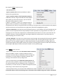
By the window “?” you can open the files summary, topic and
Programmer’s manual, know all the information about the
version of the program Master-Design that you are using and
is also possible to connect to the Tips’ HelpDesk. The HelpDesk
gives to the customers the possibility to contact us for every
doubt or problem about our software or for updates. The
customer can also use automatic update service which needs
to be booked on the site www.tipshelpdesk.com. Clicking on
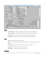
“Preferences” the program will open a window like the one
below:
Under “Preferences” is possible:
-under “Visualization” to choose to activate/deactivate the price list window on the top, to view the
price list window with tutor or not and choose the price list character dimension.
17 | P a g e
-under “Start-Up” to choose if you want to show during the start of the program the quotation
window or the project window or if you want to show (again at the start of the program) the
window of choice of user, of language or neither.
-under “Project” to choose if you want to use the autozoom every time you insert a new article, if
you want to activate the restore of the operations setting how many time can be done, if you want
to do an auto backup every time you chose and if you want to activate the Auto Redim Prj3D to
resize slightly the elements on 3D view to make clearer the separations between them.
-under “External CAD 2D” to choose: the path where there is the external CAD executable, the
description that will appear with the external CAD activation functions, the extension of the file to
import that can be DWG/DXF/WMF/EMF and if you want to wait till the exit from CAD to return to
PLAN or to work concurrently with both.
-under “External CAD 3D” tho choose as the external 2D CAD: the path for the executable, the
description, the extension of the file to import that can be DWG/DXF and if you want to wait till the
exit from CAD to return to PLAN or to work concurrently with both. More than “External CAD 2D”
there is a check box “Set Layer” that if is active causes that the imported article in CAD is divided
into layers and “Translation type” that allow that the reimported article into PLAN will automatically
put at the origin.
On the menu bar there are also the buttons [ALBUM], [PREVENTIVO] e [ICON] which features are already
deducible from the names and are used to open the photographic album, the quotation and using ICON
reduce all the Master-Design windows.
18 | P a g e
SKIN AND MOUSE FUNCTIONS
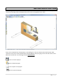
Mater-Design interface is extremely User Friendly thanks to the icons that are disposed horizontally and
vertically at the edge of the working window, this set of icons together form a “Skin”.
Every icon is associated to a functionality, so by clicking on it, the icon active a particular function. With
main icons on the skin is also possible open some dropdown menu just going over it with the mouse cursor.
Below are list the skin’s icon starting from the horizontal skin:
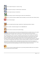
= Icon to save the project.
= Icon to load the project.
= Icon to open a new project.
= Icon to print the project.
19 | P a g e
= Icon to export the project in *.dxf and *.dwg.
=Icon to export the project to .3DS and open it with Blender.
= Icon to export the project in V3D format.
=Icon to import a project created using our software for Android devices.
= Icon to transfer the project to Blender with the possibility to set the render and resolution quality.
= Icon to close del program.
= Icon to set/modify walls (this page is explained on “Wall Settings Window” chapter).
= Icon to create a standard rectangular room of 6000X4000 mm.
= Icon to choose a room from the standard settings.
=Icon to the manual insert of the walls. By activating this function is possible to insert in the project
(by using the mouse) the walls of the size you want. To proceed with the insertion, the project
automatically goes on 2D plant view; once the project is on the right visual is possible to insert the first
wall: selecting with the cursor on a point, it becomes the starting point of the inserting and, moving the
mouse, the program shows a preview of the wall starting from that point. Choosing a next point on the
plan, the wall will be inserted from the starting point to the last chosen point (final point). Once the
insertion is ended, you have the possibility to continue to insert by using the same procedure or, using the
“Esc” button or the right button of the mouse, choose to end the insertion. To help the user to do the job
more precisely, is available a window, that appears with the activation of the function and gives the
opportunity to choose the type of insertion of the wall (absolute, relative, polar, polar with relative angle,
or choosing the direction) and, depending on the choice, the values to pass to the function.
= Icon to activate the Master-Wall function. By activating the Master-Wall function, the program
opens a window like in the picture below.
20 | P a g e
The possible operations by using this window are:
-activation of the check boxes for the guided
insertion of the walls (with the insertion of the new
walls, the program will delete the walls that were
inserted previously the activation of the Master-Wall
function):
-“Dim pareti successive ortogonali” permit you to
insert two perpendicular walls by specifying only
their dimensions. Once you have entered the first
two, or once inserted others walls by using other
functions of the Master-Wall window, is possible to
insert (using the same method) ,once at the time,
other walls always placed perpendicular to the last
inserted wall.
-“Dim. Pareti successive e angolo (in *)” inserts
automatically two walls going to specify the lengths
and the measure of the angle. Once you have
entered the first two, or once inserted others walls
by using other functions of the Master-Wall window,
is possible to insert (using the same method) ,once at
the time, other walls.
-“Dim. Pareti successive e diagonale” inserts two
walls going to specify their measure and the measure
of the diagonal that links their two extremity. Also in
this case once you have entered the first two, or once
inserted others walls by using other functions of the
Master-Wall window, is possible to insert (using the
same method) ,once at the time, other walls.
-“Dim. Pareti successive e 3 diagonali da punto
qualsiasi” inserts two walls going to specify their
dimensions and the dimensions of 3 diagonals d1,d2
and d3 like once shows in the picture:
Also in this case once you have entered the first two, or once inserted others walls by using other
functions of the Master-Wall window, is possible to insert (using the same method) ,once at the
time, other walls.
-Once is chosen a type of insertion of the walls according to the check boxes analyzed in the previous rows,
is also possible to choose the environment where you want to insert them and their height.
-To the guided insertion of the walls is possible to insert the measures also using the “LEICA Disto A6”
device and the check box “LEICA Disto A6 bluetooth” is used to activate the data transfer via Bluetooth
from the detector to the pc.
21 | P a g e
-Is possible to change or ridefine the previous walls inserted using Master-Wall window, choosing them by
using the special menu.
-Cancel the inserted walls by using Master-Wall clickin on “Nuovo” button.
-Exit from window and insert the chosen walls by using the button “Fine”.
= Icon to delete all the walls inserted in the plan.
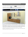
= Icon to activate the view of the furnitures in full color style. See next picture.
22 | P a g e
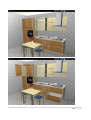
= Icon to activate the view of only the furnitures contours. See next picture.
23 | P a g e
= Icon to activate the view of the furnitures only in “iron wire” style; pratically are also displayed the
pieces inside the furnitures structure (for example shelves, back etc…), see next picture.
= Select Box for the choice of the wall where you can insert and move the articles.
= Icon to activate 2D plant view.
= Icon to activate 2D front view of the selected wall.
= Icon to activate 2D front view of all walls.
= Icon to activate 3D view.
= Icon that if is active, opens the fronts of the articles on plant view.
24 | P a g e
= Icon that if is active, close the fronts of the articles on plant view.
= Icon that if is active, shows the dimensions inside the project.
= Icon that if is active, hides the dimensions inside the project.
= Icon that if is active, shows the progressive dimensions inside the project.
= Icon that if is active, hides the progressive dimensions inside the project.
= Icon that if is active, shows the accessories inside the project.
= Icon that if is active, hide the accessories inside the project.
= Icon to show the entire page.
= Icon to zoom inside the project.
= Icon to zoom out inside the project.
= Icon to use zoom, by using mouse, just in the selected part. Once this function is active, the image
will be enlarged only within the margins of the window that will be created using mouse.
= Icon to active the function of displacement of the project view; when this function is active, the
cursor become an hand. By clicking on the project with the left button of the mouse and moving the hand,
you will move the view inside the project.
= Icon to draw a polyline by freehand everywhere inside the project.
= Icon to draw a point everywhere inside the project.
= Icon to draw a line everywhere inside the project.
25 | P a g e
= Icon to draw a polyline by freehand everywhere inside the project.
= Icon to draw a rectangle everywhere inside the project.
= Icon to draw a circle/ellipse everywhere inside the project going to define the radius.
= Icon to draw an arc everywhere inside the project.
= Icon to view a dimension between two points.
= Icon to insert a text inside the project.
= Icon to insert a text with indicator line inside the project
= Icon to import inside the project a file of DXF/DWG/VDF/EMF/WMF extension going to specify then
its features by using a window like the image below.
New object code
New object layer
New object rotation
coordinates
New object inserting
points coordinates. You
can also choice if the
dimensions must be the
orginal ones, in scale, or
defined by you
Description of the new object
Coordinates of the object
origin point
Clicking on the button “Adv.” is also possible to open the advanced features window of the object that you
want to import. An example of the window is on the image below:
26 | P a g e
To facilitate the under standing of the window and its use, below are reported the symbols with a shot
description:
-DIVFACE=[0,1,2,4,6,61..66] divide the parallelepiped into six faces constituents. You can see the
effect only on RealPhoto and serves to improve the distribution of finishes on the six faces of the
parallelepiped.
-SCX/SCY/SCZ=set the scale in x,y, and z of a 3D element, generally a DXF file.
-RTX/RTY/RTZ=rotation in degrees of a 3D element around the axis x/y/z.
-DIMX/DIMY/DIMZ=dimension in x/y/z.
-CAM90=[0|1|2|...] turns the object auomatically so that is always perpendicular to the photo
machine by using a different image in relation to the subdivision in degrees difined by the
parameter.
-NO3DRT=[0|1] If=1 disable the graphic element on the photographic studio for the rendering
“Real Time”.
-NO3DRP=[0|1] If=1 disable the graphic element on rendering "Real Photo".
-NO2DF=[0|1] If=1 disable the graphic element on 2D front view.
-NO2DP=[0|1] If=1 disable the graphic element on the 2D plant view.
27 | P a g e
-AIR3D =<size> set the air to set to the parallelepipeds on the Real Photo modality. Is used to
prevent that drawers, doors if are close they “stick” to each other. Typically the value is =4 and
corresponds to 2 mm of air on each side.
-EDGEX=<size> Set the dimension in mm for the edge to add on the X direction.
-EDGEY=<size> Set the dimension in mm for the edge to add on Y direction.
-MLT =<number of repeats in X>,< number of repeats in Y>,< number of repeats in Z>,
<stepx>,<stepy>,<stepZ>,<separate 0|1> Moltiplies the graphic symbol for n-repeat in the 3
directions.
-FIX_ORGX= Prevent, on the movements, that the X origin will be displaced.
-FIX_ORGY= Prevent, on the movements, that the Y origin will be displaced.
-FIX_ORGZ= Prevent, on the movements, that the Z origin will be displaced.
-TFC= Method to be used for the application of the texture on the element. If is set directly on the
element should be valorized after /FIN. Possible values:
• =0 the BMP map is applied on the elemtn as it is for once time, the contour is black (for
example classic doors);
• >0 the BMP map is applied on the element with the TILE effect, so is repeated till the total
filling of the element;
• =1 is repeated on all TILE sides;
• =3 is applied once on the center of the element on the 2 frontal faces and the black colour
is transparent;
• =4 is repeated on all sides; should be used if the object has an irregular shape instead of
value 1;
• =5 is like value 1 but is reported on the front/bottom top face and left face;
• =6 is like value 5 but with the surrounding space transparent;
• <0 the BMP map is considered like bump map (relief map)
• >-1;<0 indicate the intensity of the relief;
• <=-1 is considered for the decimal part the intensity of the relief and for the integer part
like colour.
-FIN=to set the finish directly on the graphic element.
-ROX/ROY/ROZ= calculates the ratio for the appropriates sizing of the finish in x/y/z.
-COL=flat colour to force on the graphic element. In the case you are using the RealRender this
parameter is determinant for the result of the final finishing because is used like diffuse colour in
combination with the possible texture causing a significant colour change and response to the light
in the object. In general is used like flat colour instead of texture on the view that doesn’t provide
in rendering.
-TSX/TSY/TSZ=<n.repetitions> scale of the texture in x/y/z.
-TRX/TRY/TRZ=<degrees> for rotation of the texture in x/y/z.
-MPX/MPY=<size> set the pixel dimension of map. If using TFC=1 must be set with rendering RealPhoto so that the repetition of the finish is right.
-TLX/TLY=<trasl. in mm> texture translation in x/y.
-FRM=[0|1] report or not the edge of a 3D element.
-FRMCOL=<colour> colour of the edge.
-CBAR=<code> indicates the code of the bar to be used for the AutoTop.
28 | P a g e
-CFIN=<code> indicates the finish code to be used in the place of the one contained in the
definition line of the finish. If isn’t set, is considered as code the name of the file texture without
extension.
-VFIN=<finish variantion > for the considered element; to the finish already given, is added the
<finish variantion>.
-ECOL=[0|1] the colour specified in COL is used to overlay the texture specified. In this way is
possible, starting from a single texture (possibly in shades of gray), to get all its colours variants by
varying the single COL parameter. By activating this function the program create automatically,
some files in the MAP directory. These files begin with TMP_RP_<col>_<finish file> and they must
be deleted if you make changes to the <finish file>.
-NRP=<,1,2,3,..A,B,..> it indicates which PRICE field it has to consider for this finish. The value can
be composed of many characters. The name of the field used for the price calculation is obtained
by adding the contents of NRP to the name of the PRICE field.
-FDIV=<num.> is an evolution of the DVY attribute and it is applicable only to Real Photo. FDIV is
useful for the doors (classic type) which change dimensions and that could be damaging if change
the dimension in X and Y. With this functionality the door finish is divided in different zones that
some of them, to the change of dimensions, will be stretched.
-TRS=<0.8 ...1> can be used also on the textures. In case of Real Photo if it’s used another texture,
it must be used always with the same level of transparency otherwise drives the first occurrence of
that finish. So if the same BMP is used for elements with different transparency (or without
transparency) the program will consider only the first value.
-FTBL=<table code> is similar to VFIN but the variantion is calculated in dynamic mode according
to a list where are established the intervals of the dimensions for X and Y separately. The resulting
VFIN takes into account the dimensions of the element where it will be applied and for each range
combination of Y-X returns its combination. The resulting variantion is obtained by the
combination of the calculated variantion Y and the calculated variantion X. The list of the
combinations is indicated on Database DESIGNER.INI file.
-FRL=<finish name1>;<finish name1> Set the finish name to be considered in the Real-Photo mode.
-LUC=[0|1|100...110] Indicate that the current finish is a polished finish. It applies only in RealPhoto.
-FFIX=[0,1] If is set to 1 aren’t impossible any finish changes.
There is also a box for entering the code of RGB colours and their preview.
=Icon to draw a parallelepiped inside the project going to specify the layer where you want to insert it
and, if you are drawing on 2D plant, the position and the dimension on y. If you are drawing on 2D front the
program will ask you instead y, the position on z and how many it has to extrude on z.
=Icon to draw a cylinder inside the project going to specify the layer where you want to insert it, the y
center on 2D plant, the z center on 2D front and the height.
=Icon to draw a sphere inside the project going to specify where you want to insert it, the y position on
2D plant, the z position on 2D front and the radius.
29 | P a g e
= Icon to draw an extruded trapeze inside the project going to specify the layer where you want to
insert it, the position and the dimension on y on 2D plant, the position and the dimension in z on 2D front
and the angle left and right.
= Icon to import inside the project a DXF/DWG/VDF file. Also in this case must be specified the
features inside a window like the one below, that it is very similar to the reported window for the insertion
of DXF/DWG/VDF/EMF/WMF file.
Still using “Adv.” Button, the program will open the advanced features in a window like the one reported
above.
= Icon to draw a polyline extrusion inside the project going to specify the layer where you want to
insert it and, if you are drawing on 2D plant, the y position and how many you have to extrude on y. If you
are drawing on 2D front the program will ask you instead y, the z position and how many you have to
extrude on z.
=Icon to draw an extrusion discharge from polyline inside the project going to specify the layer where
you want to insert it and, if you are drawing on 2D plant, the y position and how many you have to extrude
30 | P a g e
on y. If you are drawing on 2D front the program will ask you instead y, the z position and how many you
have to extrude on z.
=Icon to draw a polygon extrusion inside the project going to specify the layer where you want to insert
it and, if you are drawing on 2D plant, the y position and how many you have to extrude on y. If you are
drawing on 2D front the program will ask you instead y, the z position and how many you have to extrude
on z.
= Icon to draw a tube inside the project going to specify the y on 2D plant, the z on 2D front and the
radius.
= Icon to insert a light source inside the project going to specify the y on 2D plant, the z on 2D front, the
type of light expressed as a numeric value (0 - omnidirectional light, -1 - solar light, 1…180 - directional
light, spot light) and the Watt power.
= Icon to modify the project by using MD-CAD.
= Icon to create an element by using MD-CAD.
=Icon to activate the multi-select function of the elements on the project.
= Icon to select all the articles belonging to a wall.
= Icon to select all the project articles.
= Icon to select all the aesthetic accessories belonging to a wall.
= Icon to select all the designed directly by using the functions of drawings of the current wall .
= Icon to redraw all the project articles.
= Icon to regenerate all the project articles.
31 | P a g e
= Icon to view the mouse functionality in a
window like the one reported on right.
= Icon to active the function to
measure the distance between two points.
=Icon to active the vertical and the
horizontal ruler.
=Icon to activate the SNAP option
window. Is very important to configure properly
these options, because otherwise you may have
difficult to move the pieces which follow these rules for shifting
and hooking with other furnishings or with other walls.
=Icon to cancel the last article that was inserted.
= Icons to change the “Skin” to modality
“ADVANCED”, “SIMPLE”, “MINI” and “CAD”. The Advanced
modality is the most complete because provides all the functions
and icons; the Simple modality provides the essential icons so the
job is more intuitive and easier; the Mini modality is like Advanced
modality but the icons are smaller. The Cad modality is like
Advanced modality with the add of geometric drawing icons on
the vertical skin so is easier to find them because you don’t have
to search them on the menus.
=Link to http://www.masterdesign.it/ site.
Now that we have examinate all the horizontal Skins’ function, we can examinate the vertical Skins
functions:
32 | P a g e
= Icon to open the price list.
= Icon to open the finishes window.
=Icon to give the quotation.
=Icon to open Virtual 3D. Going to put the cursor above this icon the program will open a little
. The first icon on left allow to open the
menu like the one on right
camera set, the second one activate the function to open the light set and the third one opens the Blender
program. The explanation in detail of this functions will be done on the Virtual 3D chapter.
=Icon that allows to use of the mouse left button to open the article menu.
=Icon that allows to use the mouse left button to open article TOOL-PAD.
= Icon that allows to use the mouse left button to open the article finish window.
= Icon that allows to use the mouse left button to open the article finish window of a part of an
article.
= Icon that allows to use the mouse left button to delete an article.
= Icon that allows to use the mouse left button to move an article.
= Icon that allows to use the mouse left button to copy an article.
33 | P a g e
= Icon that allows to use the mouse left button to show the information tab of an article.
= Icon that allows, by clicking on the plan using the left button of the mouse, to activate the
multiple selection.
= Icon to activate the TOOL-PAD just moving your mouse over an article .
=Icon to activate the TOOL-PAD of all articles.
= Icon to disactivate TOOL-PAD of all articles.
= This icon if is activated, active the Mode Chain. When this function is On, the program
automatically goes on 2D front and on the base of each article will appear some commands as shown
below.
34 | P a g e
-By activating the green arrow on the right or on the left, the article according to the direction of the arrow
will change position with the article that stands beside its. For example if you select the left arrow, it will
change position with the article that stands on the right of its and so on. If the item isn’t attached to
another one, the command will not have effect.
-By using the brown arrow the article will separate from the one that stands on the right or on the left of it
of a certain value given in input.
-The double azure arrow serve sto add on the left or on the right of the article another item by choosing it
from the price list.
-By using the double curved arrow on the center you can replace the article whith another one by choosing
on the price list.
-By using the X on the center the article will be deleted.
=This icon if is active the Mode Chain is disabled.
35 | P a g e
= Icon to active the Position Check.
= Icon to disable the Position Check.
On the bottom of Master Design there is the view of the mouse position coordinates, so moving it on the
plan you will see update the values of x and y on 2D front, of x and z on 2D plant and of all 3 axes on 3D
view.
Still at the bottom there are 4 buttons that are set to ON or OFF as shown in figure.
Their functions are:
- “SNAP” to activate/deactivate the project grid;
- “GRID” to activate/deactivate the view of the project grid;
- “ORTHO” if is active, any graphic design you are moving, it will move only in parallel to the axes;
- “OSNAP” to activate/deactivate SNAP.
Near the OSNAP button there is a small window that shows the description of every active object or
function and also mouse features that are set.
36 | P a g e
WHAT IS TOOL-PAD
When TOOL-PAD is active, above each article the program will activate an icon. Every time that you move
the mouse over it, will be shown the article description and below a star menu that provide some
commands. An example of TOOL-PAD is shown on the figure below.
Doing a zoom to the article you will see that TOOL-PAD is represented by the following icon:
37 | P a g e
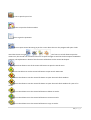
The TOOL-PAD icons are:
-
Icon to view the article variants.
-
Icon to view the article information.
Icon to change graphically the z dimension of the article. When you use this command the
program will open automatically the 2D plant view.
Icon to change graphically the y dimension of the article. When you use this command the
program will open automatically the 2D front view.
-
Icon to change graphically the x dimension of the article.
-
Icon to change the opening side of the article leafs.
-
Icon to choose the article finish.
-
Icon to copy the article and insert it on the project.
-
Icon to move the article on the plan.
-
Icon to delete the article.
Some articles has on TOOL-PAD also another icon to insert other elements like for example the sink, the
hob etc.. depending to
the use of the article, you
can add more or less
items on the article at
your discretion.
38 | P a g e
Also in this case (image on left) going over the icon to insert oter
items by using the mouse, the program will open a star menu with
the article description on the top and under of it the available
options arranged in a star. By clicking on the item image that you
want to insert (hood, oven etc..) the program automatically opens
the price list that contains all the available items for that kind of
element.
When TOOL-PAD is active and you select a wall, if you move the
mouse cursor of its ends, the program will open another star menu
with all the wall settings and on the top the wall description.
Here are illustrated the icons with their functions:
Icon to active the function to move the ending
point of the wall. By activating this function you can
move graphically the ending point of the wall;
Icon to active the function to move the
starting point of the wall. By activating this function
you can move graphically the starting point of the
wall;
Icon to set by an input value the width of the
selected wall.
Icon to active the wall edit going to open a
window with all the setting for the customizations. By
using wall edit you can change the wall description,
the position, the width, the angle, the wall ambient,
etc..
-
Icon to delete the wall.
Icon to join the selected wall with the following wall.
39 | P a g e
Icon to divide the selected wall in two walls. By activating this command, the program will open a
window that ask in input the x point of the wall and it will be the origin of the new wall.
-
Icon to add a new perpendicular wall to the selected one dividing it in two walls.
-
Icon to add a perpendicular wall to the selected one.
-
Icon to add a wall behind the selected one.
-
Icon to add walls to the end of the selected one..
Icon to move the articles from the selected wall to another one choosing it from a list of available
inserted walls.
Icon to active the moving function of the articles to the right of the wall. When this command is
active, the program will change the view automatically in 2D front of the selected wall. Then the program
will ask in input which is the distance from the extreme right of the wall where it have to put the articles.
Icon to active the moving function of the articles to the left of the wall. When this command is
active, the program will change the view automatically in 2D front of the selected wall. Then the program
will ask in input which is the distance from the extreme left of the wall where it have to put the articles.
40 | P a g e
ARTICLE MENU
The article menu is the menu that is opened by the program going to click using the left mouse button on
an article. Is possible to open this menu only if is active the function to open the article menu by clicking on
it. On the article menu there are:
-
The article code with its description: opens another menu to examine the article Basic Lists.
-
The function “Deactivate in 3D”: if is active the
article is invisible on Virtual 3D.
-
“MARKER”: are used to realize management
mechanism and volumetric control:
-
o
“Show all Marker” to show all Markers;
o
“Show Marker Work Surfaces” to show ‘work
surface’ markers;
o
“Show Marker Works” to show ‘working’
markers.
“Move”: opens a menu where you can choose the
move modality that can be applied to the article.
Once you have chosen a move modality is possible to
move the article. Is also possible, by activating the
function “Change Projection”, to open another
window where you can choose the projection (the
wall) where you want to put the article. When you
use the move modality “with Mouse ATTACH” is also
possible to activate other functions:
o
Clicking on ctrl+Q the program leaves the
move modality and actives the copy function
of the article
o
Clicking on ctrl+S the program leaves the
move modality and actives the relative move
function
o
Clicking on ctrl+M the program leaves the
move modality and actives copy n-times
function
41 | P a g e
-
“Rotation”: is used to open another menu where is possible to choose the type of rotation that you
want to apply to the article. Once you have chosen the type of rotation, is possible to rotate the
article depending on the choice made. By using this menu is also possible to active the “Reset”
button to cancel every done operation.
-
“Copy”: is used to copy the selected article and to choose, by using the menu that the program
opens, the position where you want to put it (like on “Move” menu). With the function “Multiply ntime” is required in input the number of time that you want to copy the article and the position
from the article to copy. Giving in input the value 5 on the choosing window of the number of copy
and the value X=200,Y=0,Z=0 on the relative position choice, the program will create other 5
articles like the copied one and it will place them to 200 mm of distance from each other. The
distance is 200 mm from the insertion point of the previous article. If the new articles can’t be
inserted at the specified location because is occupied, they will place automatically on the first free
position they find.
-
“Clone”: opens a menu equal to the one of the “Copy” function; by using “Clone” you can insert a
clone article from the selected one and you can choose the insert position. Is also possible, using
this function, to transform the selected article in a clone one (if it isn’t a clone), obviously you had
to define previously a “father” article. The difference between “Copy” function and “Clone”
function is that the clone takes the article definition from the “father” element, so it weight much
less than the copy element.
-
The “ONLY THIS” function: if is active, is used to make visible in the view which you are activating
this function only the selected article. Doing a redraw or changing the view, everything return
normal.
-
“Front only selection”: if is active you can view on 2D front only the selected article. Changing the
view, the program return to display also the other articles.
-
“Finish”: opens the finishes window, so you have the possibility to choose the finishes for the
selected article.
-
“Variants”: opens a window where are shown all the selected article variants and you have the
possibility to change their values (the windows will be illustrated in details on “Variants Window”
chapter).
-
“Graphic Transformation”: opens a menu where you can choose the graphic transformations to
apply at he article. The graphic transformations are:
o
“Rotation 3D”: is used to rotate the selected article as much as a value that you give in
input. You can also define the X,Y,Z object rotation points. Reloading the article, the
program cancel the rotation effects.
o
“Rotation 3D X axis“: is used to rotate the selected article around the X axis as much as a
value that you give in input. You can define also the object rotation points X,Y,Z. Reloading
the article, the program cancel the rotation effects.
42 | P a g e
o
“Rotation 3D Y axis“: is
used to rotate the
selected article around
the Y axis as much as a
value that you give in
input. You can define
also the object rotation
points X,Y,Z. Reloading
the article, the program
cancel the rotation
effects.
“Rotation 3D Z axis“:is
used to rotate the
selected article around
the Z axis as much as a
value that you give in
input. You can define also the object rotation points X,Y,Z. Reloading the article, the
program cancel the rotation effects.
o
o
“Scale”: is used to insert the object scale value.
o
“Pen Type”: is used to modify the article boundary depending on the value that you pass to
it:
0 - Solid
1 - Dash
2 - Dot
3 - Dash-Dot
4 - Dash-Dot-Dot
5 - Transparent
6 - Inside Solid
-
o
“Pen Width”: is used to modify the boundary pen thickness of the selected article.
o
“Pen Color”: is used to change the boundary pen colour of the selected article.
o
“Change Order” to change the order which the graphic element is drawn compared to the
other elements.
o
“Reset Transformations”: is used to reset all the graphic transformations effects.
“Build Element from Selection”: if is active, creates a new article from the selected one. About the
new article, you have to specify the registry and you can also personalize it by using some check
boxes:
o
“SetModel_Ele” is used to set directly on it the model;
43 | P a g e
o
“Set Variants” is used to set the variants;
o
Set levelDB” is used to add to each element the dynamic field /LvDB0 so you can force the
element to level 0 of the basic list;
o
”ELEMENTO come ElementoDB (/EleDB1)” is used to considerate the selected elements as
ElementiDB.
o
“Pos.rel. ...PosX,…PosY,…PosZ” is used to set the element position directly inside the
parameters (PosX, PosY and PosZ) instead on Elemento/ElementoDB;
o
“EXECUTE TAL: NEW_ART_<nome_par>.TAL“ when the program finds the parameter
<nome_par>, the program executes the indicated TAL.
o
“EXECUTE TAL: NEW_ART.TAL” is used to execute TAL before the initialization of the single
parameter.
o
“Global Variants” is used to set global variants to the new article;
o
“Insert Piano” is used to insert the layer of the new article.
o
“Insert “{Variant_ToVar}”” is used to make the article variants independents from the ones
of the other articles (to prevent that if the variants are the same for another inserted
article, they don’t influence with their values also the article that you are using)
o
“Insert “Redraw”” is used to make on the project a redraw in the actual view.
-
“Delete”: is used to delete the article from the project.
-
“Split”: on the 3D view, permits to reassembly graphically an article which was exploded by using
the “Explode” function.
-
“Explode”: on the 3D view, permits to explode graphically the selected article.
-
“Reload Element”: to reload the selected article.
-
“Reload Element variants”: to reload the variants of the selected article.
-
“Replace with…”: serves to replace the selected article with another one choosing it by using the
price list. If the replacement article doesn’t enter in the position of the article to replace, it will be
inserted by the program on the first free place in the plan.
-
“Replace with… variants”: serves to replace the selected article with another one choosing it by
using the price list and pass to the replacement article the variant values of the article to replace.
-
“List”: is used to open the Basic List window. (the Basic List window will explained on its chapter)
-
“Edit Fields”: is used to open in another window a part of the selected article’s registry with the
possibility to modify it, the price, etc… The changes done by using this page are temporary and not
permanent, reloading the article the program cancel the changes.
44 | P a g e
-
“Make Static”: is used to make the article from parametric to static, so to make it fixed to its
measures.
-
“Edit Article”: to open the Edit Article window. (the Edit Article window is shown in details on its
chapter)
-
“Export selected objects”: is used to export all the objects owned by the selected article in a
directory specified by user in .MDOBJ format. By using check boxes is possible to customize the
export based on what they indicate.
-
“Dim.X”: If is active you can choose graphically the new X dimension of the selected article.
-
“Dim.Y”: If is active you can choose graphically the new Y dimension of the selected article.
-
“Dim.Z”: If is active you can choose graphically the new Z dimension of the selected article.
-
“WIZARD Edit”: if is active, it actives WIZARD of the selected article.
-
“Exit”: to exit from the article menu.
45 | P a g e
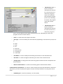
WALL SETTINGS WINDOW
Wall settings window is used, as suggest its name, to insert walls inside the environment or to change
them. This window is automatically opened by the program when you start the creation of a new
environment or can be opened using wall icon inside the program skin.
As we can see inside the image the possible operation are:
- Don’t insert any wall inside the project: in this case the environment will be empty and the articles can be
inserted inside the space without limitations.
- Insert standard walls: in this case you can choose standard walls by using an apposite list. As you can see
fro the image, the selected wall typology is shown thanks to a preview on the right side of the window;
inside this image are
identified the walls
by a letter and the
angles by Greek
alphabet letters. The
user can also modify
the environment
going to change the
numeric values
inside the boxes on
the left of the
preview image. By clicking on the coloured box on the left of the standard environment preview, the
program opens another window where you can choose the wall finishes; once you have chosen the box
takes the finish chosen colour Instead by selecting the boxes “FLOOR” and “CEILING” is possible to choose
(always by using a new window) the floor and ceiling finishes; also on this case the box takes the finish
chosen colour.
- Insert customized walls: user by activating the checkbox “Free” can creates freely the walls that he
prefers going to choose and define all parameters (dimensions, finishes, environments etc…). Although
previously inside the project were inserted standard walls or customized walls, however they appears
inside the page
“Free” so you can
modify and assign
them to an
environment. By
using this page is
possible to
customize also
floors and ceilings.
Clicking on icon
46 | P a g e
“free” is possible to insert walls by freehand inside the project. Once you active the function, the program
opens a window (like ones on the pictures below) to help the user to insert the walls. Every time that you
create a wall, it’s automatically added by the program inside the list of the checkbox “Free”.
The insertion modality by freehand are:
-“Absolute”: the coordinates X and Z inserted (that they determinates the final point of the new wall) take
into account as origin point the axis origin.
-“Relative”: the coordinates LX and LZ inserted (that they determinates the final point of the new wall) take
into account as origin point the final point of the last inserted wall or a point chosen by the user that
become the origin point of the new wall.
-“Polar”: the final point of the new wall is determined by inserting into “Ang” the angle and into “L” the
length of the new wall. The angle inserted by using checkbox “Polar” is absolute.
-“Polar Ang Rel”: like “Polar” the final point of the new wall is determined by inserting into “Ang” the angle
and into “L” the length of the new wall. In this case the inserted angle is relative to the previous wall (next
figure).
47 | P a g e
90°
270°
90°
45°
-“Direction”: the final point of the new wall is determined by inserting just the wall length. Once inserted
the dimension and pressed “Enter” button, the program creates a wall length like the inserted value and in
direction of the cursor inside the project.
By using the button “+”, that it’s always inside the insertion help window, you can
choose a point in the space and the program automatically takes its coordinates
and inserts them inside the help window.
Is also possible indifferently of any used function, to insert the walls easily giving in
input the length of the new wall nearby the row that indicates the wall direction.
By inserting the new wall length nearby the number “45” the program
automatically draws the new wall with chosen length with an absolute angle of
45°. “Sp” instead determines the thickness of the new wall.
Clicking on “End” the program exits from the insertion help window and returns to the wall settings
window under the checkbox “Free” and inserts inside the list all the new walls.
Instead pressing on the right button of mouse device during the insertion with help window, the program
sends to you a message to confirm the conclusion of the wall insertion. Clicking on “Si” the program ends
the insertion, close the help window and inserts the walls inside the list of the checkbox “Free” (like clicking
on “End”), otherwise stay open the help window.
48 | P a g e
Turning back to talk about the wall settings window, the last checkbox to examine is “Library” that allows
you to choose standard rooms by using out library.
The checkbox “Show only the line” is used to show the walls on 2D view like lines ignoring their thickness.
49 | P a g e
FINISHES WINDOW
Using the finishes window is possible to load the desired finish for each available layer on the furniture line
that you want to use. On the top of the window there is the name of the furniture line that the user chose,
lower there are the layers names with the finishes preview that the program applies on them. By clicking on
the finish preview, on the layer name on its preview image, the program opens another window where are
listed all the possible finishes for that layer divided in groups and represented by their own preview image;
by using this new window, you can change the finishes for the selected layer by clicking on finish
description or on its preview .
Chosen finish preview
Layer preview
Layer name
Chosen finish description
50 | P a g e
Clicking on the icon
(“Parameters”) the program opens another window where are listed all the line
furniture’s variants that with the possibility to change their values.
Clicking on
(“Advanced”) the program opens a new finishes advanced setting window.
Clicking on the icon
the program opens the finishes insertion WIZARD. By using this function, the
program opens step by step each layer for the selected model and the user can choose for each layer the
finish that he prefers. Using the icon
page and applies the chosen finishes.
the program exits from WIZARD,opens the standard finishes
The icons
and
are used to exit from finishes window without apply the modify and exit
from finishes window applying every change or modify done.
51 | P a g e
Next image shows the window opened by the program clicking on
.
List of the
finishes
combinations
previously
saved for each
layer
Previews of the
selected
finishes
Previews of the
selected finish
Model variants
Button to open
the window
where you can
choose the
finishes
Finishes list
Layers list
Model that you
are using
52 | P a g e
As we can see from the image there is on the top a dropdown menu to choose combinations of finishes
previously defined. Selecting the desired combination, automatically each layer will get the chosen finishes
for the selected combination. Using “Combinations” is also possible to delete a previously created
combination by clicking on “-“, or add all the chosen finishes for the layers to a new combination specifying
the name and then clicking on “+”.
Once you have checked the check box near the
name of the layer for which you want to choose
the finish, the program will activate a dropdown
menu with the choice of finishes for the that
layer.
Still on the finishes advanced setting
window: activating the button “!” (or
clicking on a finish image on the main
window) the program opens another
window (the figure on the left) where are
listed all the possible finishes divided on
groups and represented by their own
description and their own preview image.
(Is the same page that the program opens
when you click on a layer on the main
finishes window). On the top of the
window there is the name of the chosen
layer. By clicking on “abort” on the bottom
of the page, the program closes the
window.
53 | P a g e
Clicking on the finish preview on the finishes advanced setting window, near the finishes dropdown menu
of the selected layer, the program will open another window where there are all the finish details. The
fields are modifiable so you can change their values. The symbols are the same illustrated from page 27 to
page 29.
Still on the finish details window: on the top, along the window frame, is specified the number of the layer
for which you are going to change the finish, on the first line there is the finish code and on the second line
there its description.
Clicking on “Ok” on the main finishes window or also on the finishes advanced setting window, all the
selected finishes will be saved for every layer and then they will be viewed on the project.
54 | P a g e
VARIANTS WINDOW
On this short chapter we are going to examine the variants window. This window can be opened using the
Finishes Window or using Article Menu. Obviously depending on the article which is used to open the
variants window and depending
on the furniture line that you
are using, the program reports
the relative variants. As you can
see from the figure on the right,
the variants are disposed by
category and are all modifiable.
Once you modify a value, you
have to click on “Ok” to apply
the change. The window on
figure is the one which is
opened clicking on “Advanced”
on the finishes window; the
window opened from an article,
reports instead of the line of
furniture name, the price list
image of the selected article
and its features and below
there are the variants available
for the selected article.
55 | P a g e
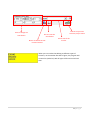
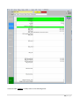
QUOTATION
Clicking on the quotation icon, the program will open in another window the quotation which contains all
the articles used inside the project. When you open it, the project goes on 2D front view and the price list is
replaced with a new page like the one below.
As you can see from the picture
on left, on the page that the
program opens instead of the
price list reports the date and the
time when the quotation is
elaborated, is specified the type of
furniture, all the articles that are
inserted with their codes,
descriptions and quotas and in the
bottom of all there is the total
price in Euro.
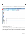
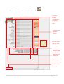
The quotation window id reported on the next page.
56 | P a g e
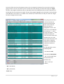
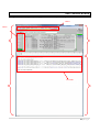
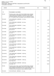
Article list (highlighted in red)
with basic lists
57 | P a g e
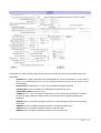
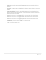
As shown on the image, the Master-Design quotation allows many operations, many are selectable by using
the menus on the top of the window. Below there are all quotation fields:
-on the “Code” field there is the quotation code;
-on the “Customer” field there is the customer number and near of it the program shows its name, the
address and the city;
-“Price List” is used to select the type of price list;
-near “Ordine” (Order), “Trasferimento” (Transfer) and “Carico” (Laden) you can insert the order date
(generally the program insert it automatically when you elaborate the quotation), transfer and load. You
have also the possibility to insert manually the date or automatically going to open the dropdown menu
under “Stato” (State). Selecting a voice (Ordine, Trasferimento, Carico) under “Stato”, the program inserts
automatically the date on the relative field;
- on “Tipo” (Type) field is specified the type of order, of transfer and of load;
- there’s also the possibility to insert the delivery dates on the relative field;
- on “NOTES” field you can insert all the notes about the quotation;
- on “Model” field there is the used type of furniture;
- “Variants” shows all used variants;
- “Notes x Prod.” Allows to insert production notes;
- “Reference”is used to insert the order reference;
- on the right side there are all the details about the articles cost in Euro with the possibility to modify and
insert any discount. Is also possible to specify the exchange with another foreign currency. If you do some
changes, the program automatically recalculate the total price;
- You can choose to activate/disactivate the elaboration of the images, of prices, of encoding and of the
other schemes by selecting/deselecting the relative fields.
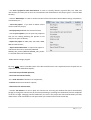
Now we examine the functions contained on the menu situated of the quotation window:
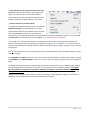
By using “File” menu you can:
- create a new order;
- load an existing order: the program opens a list where you can
do a quick search going to filter only the orders that have the
information specified by using specifying fields (for example the
customer description);
- save a new order;
- delete an existing order: in this case the program requires the
number of the order to delete;
- open the printer settings;
- import new projects: also in this case you can choose the
projects by using a list and to facilitate the search you can filter
the projects;
- by using “Reply” menu is possible to restore or check a new
order going to specify its number;
58 | P a g e
- change DataBase going to choose it by using a list of recently used DataBases or loading a new one
specifying the path;
- exit by the Master-Design program;
Using “Edit” menu you can:
- clear the detail: all the quotation fields about the
articles information will be deleted;
- show the article in the project: if is active, the
program goes on the project on 2D front view and
highlights the boundaries of the article selected on
the quotation (in the quotation just selecting a cell of
the article row to select the entire element);
- delete a row;
- insert a row;
- search starting from a selected column the
subsequent rows going to specify the text: it is used
to search some characters on the subsequent rows
from a selected one in the chosen column;
- continue the search that was carried out;
- open the window where there are the variants of the selected article (also in this case just selecting a cell
of the article row to select the entire element);
- hide the basic list: activating this function the program shows on the quotation only the articles exluding
the basic lists.
- elaborate the basic list: when is active, the quotation list is displayed as shown on page 51: with all
articles and basic lists. If the command is disabled, on the quotation list the program shows the main sale
articles. Every time that the function is enabled or disabled you have to rework the quotation to make the
change.
By using “Print” menu:
- is possible to print the quotation and view a preview image before printing;
- is possible to choose in detail the fields to insert on the quotation to print; the possible fields are
showed on the picture at the next page with an example of Master-Design quotation:
59 | P a g e
As you can see on the picture
there are many the options that
you can activate to make
detailed the quotation print.
Going to check “3D
Axonometry”, “Image head-on”
and “Map Image” the program
inserts on the print the images
on 2D plant view, 2D front view
and the 3D axonometry. Using
“3D Render” you can choose the
type of rendering to view on the
quotation print if is active “3D
Axonometry”. Going to active
“IMAGES ON SEPARATED
SHEETS”, the images of the
project on 2D plant, 2D front and
3D will be distributed ones for
pages and not all three in a one
sheet. Is possible to regroup the
quotation articles showed in the
print in: Environments, Models,
Structures etc.. so is easier to
read the table-list of the
reported articles. Is also possible
to add/remove from the article
list the columns relative to the
articles: Environments,
Projection and Model by using
their commands. You can also
add/remove: the articles images
using “Image Article”, the prices
details using “Prices details” and
the price of each article using “Unitary Price”. By using the check-box “Estimation details” you can add or
completely remove from the print the table which contains all details of the inserted articles. By using
“Total” you can add or remove all the details about total price, using “Discount” is possible to add or
remove all the details about the discount. There is also the possibility to enclose files to the quotation
specifying the path. You can also choose the language, choose to view or omit the currency and the foreign
currency and to add the header and the logo. Using “Dim Car” you can choose the characters dimension of
the quotation print. On the pages below there is an example of the print preview (with inserted two test
articles) with active the functions shows on the previous image.
60 | P a g e
61 | P a g e
62 | P a g e
63 | P a g e
By using the “Utility” menu you can:
- calc the total price;
- open a customers list with the possibility to make a
search of the specified text;
- open in another window a list of quotations projects
ordered by code. By using the window that the program
opens when you active this function, you can view the
quotations filtering them by “Stato”
(“Ordine”,”Trasferito”,”Carico”), by customers code, by
agentes code or by the date. Is also possible to change
the quotation list order by using check boxes. By clicking on a project field, it will be opened by the program
and the articles that on the quotation main page were yellow will be highlighted in green;
- delete a composition: using this function the program opens in a new window a list (less detailed than the
previous one) of compositions with the possibility to search quotations by using the date and “Stato”. On
this page you can choose the compositions to delete definitely from the list and, once you choose the one
to delete, clicking on “Eliminate Selected” the program deletes the selected ones. If you don’t want to
delete anything you can click on “Exit”;
- activate “MarkUp” if you want to increase the price in percentage. By activating this function the program
opens a page where is required a numeric input that represents the increasing percentage of the price.
Clicking on “Ok” the program suggests to rework the quotation to make effective the change. When you
rework the quotation, the program reminds you the price increasing with the red text “MK:*input value*%”
(for example: MK:10%) on the left of the word “EURO” on the quotation page.
Using “DBase” menu you can:
- open a new window with all the information about customers,
where is possible: to open a customer selecting it from a
customers list where they are divided by code, to change the
information, to create, delete or duplicate customers and
moving on the customers list by using arrows.
- open a window with all the information about articles and
also in this case is possible: to open an article selecting it from
an articles list where they are divided by code, to change the
information, to create new ones, to delete and duplicate articles
and moving on the articles list by using arrows.
- like the previous cases, you can open other windows that reads on DataBase and in particular about:
information about articles and articles groups, information about models and groups model, information
64 | P a g e
about the orders, information about the users, information about price lists and information about
finishes.
Below there is an example image of the function about the customers information.
Under the “Server” menu is possible to set the PC where you are working as Client for the PLAN-SERVER
management. With the PLAN-SERVER management is possible to dedicate a workstation for the automatic
management of the print activities and for others automatic activities to the condition change of the
composition. One or more web PCs can be set as SERVER and the other ones as CLIENT. The SERVER
setting occur using the command line instead the CLIENT settings through the SERVER menu on the
QUOTATION main page. For the CLIENT, on every PC restart, the program will set the last chosen modality.
The PLANs also if aren’t set like CLIENT, they can use the SERVER activities creating a record on the
SERVER_PLAN table. SERVER can be started on the same machine where you start the PLAN if the granted
license data allow it otherwise you must start PLAN on another PC.
65 | P a g e
The operations that SERVER must execute are reported on a dedicated table SERVER_PLAN that is
automatically valorised by PLAN in CLIENT modality. Alternatively you can also use the TAL to valorise the
table fields. In this last case is advisable to valorise the ACTIVITY field by using TAL istructions.
Before activating this functions is advisable to set on DATABASE the table SERVER_PLAN with the following
structure:
Table Name: SERVER_PLAN
Codice (Code)
Counter
Data_Richiesta (Date
Request)
Date/Time
Ora_Richiesta (Time
request)
Text
Utente (User)
Text
NCommessa (Order
Number)
Long Integer
8
50
Name of PC which made the
request
Reports the title of the section to
execute in STAMPE.INI.
Attivita (Activity)
Text
Descrizione_Attivita
(Description Activated)
Text
DaSvolgere (To Do)
Yes/No
Conclusa (Concluded)
Yes/No
Data_Conclusione
(Conclusion Date)
Date/Time
Ora_Conclusione
(Conclusion Time)
Text
Tempo_impiegato (Time
Used)
Long Integer
50 or + It can contains, alternatively, TAL
instructions that are recognized
because of the presence of
braces.
50 or +
8
66 | P a g e
Errore Errore (Error)
Text
50 or +
The “?” menu and the [ALBUM] and [ICON] functions are the same of the ones explained on the Menu Bar
chapter, instead the [PROJECT] function is used to go to the quotation page to the project page.
Under the quotation page menus, clicking on the function “ALLEGATI”, is possible to open a page (that it
will substitute the top of the quotation page) where you can insert, view and in case delete the annexes.
To return on the previous page you have to click on “MAIN”.
Using the side icons on the quotation page is possible (are listed the icon functions according to their
position from the top to bottom):
- save a compostion;
- load a composition;
- create a new composition;
- open the quotation preview and then print it.
67 | P a g e
68 | P a g e
BASIC LIST WINDOW
69 | P a g e
Artiche tree
list with the
explosion of
the basic lists
By activating or
deactivating this
boxes, is possible
to choose what
you want to view
inside the project.
The layer list on
the right can be
examined by using
the buttons “UP“
and “DOWN”
Articles for sale
On the Basic List Window are listed all the articles that are inserted on the project. They can be viewed
using a tree structure (“Tree”), that allows with double click on an article to view its basic list (the list of all
the pieces that compose the article)(“TreeDB”), or viewing a grid like the one in the picture below (“Grid”).
In the case of grid view, are shown for each row the articles and their own basic lists. The main articles are
70 | P a g e
the roots of the trees that the program create; you can change the selection from an article to another
going to select it on the tree view. If you are on the tree view, selecting an article and using the “Single”
function, the program considerate only its code with its basic lists hiding the other articles inside the tree.
On the grid view if you active the “Single” function the program highlights only the fields of the article that
was selected on tree view or in “TreeDB” view. Instead if you select a basic list and you active the “Single”
function the page become empty.
Using the grid view there
is for each article the
detail of the processed
rows. In this case the
father articles are
highlighted in azure. The
basic lists are preceded by
the character “_”; more
are the characters “_” that
precede the basic list
name and more mean that
the basic list is on a low
layer inside the article. The
layers level is based on
how much is nested the
method call inside the
program.
On the grid there are the
following fields:
- the element code;
- the element description;
- “Pr”: is the number that
corresponds to the
element wall;
- “Pn”: is the layer
number;
- “DF”: front detail;
- “DP”: plant detail;
- finish code;
71 | P a g e
- “Simbol”: are the instructions used on the code to create the element (on the grid, only the elements
that contain “REM_MARKER” inside the symbols are highlighted in green and they are the elements which
the TAL code pass parameters)
- the parameters passed to the commands;
- the X origin;
- the Y origin;
- the Z origin;
- the rotation;
- the rotation center on X (C.R.X);
- the rotation center on Y (C.R.Y);
- the commands elaboration (it is also in a column which is called “Simbol”);
- the parameters elaboration (it is also in a column which is called “Parameter”);
- the basic list level (L.DB);
- “IDunì”: is an unique ID field of the project row.
Now we are going to examine the menus situated on the top of the page.
Under “Options” there are two actively functions that allow you to choose to show only the elements of
the projection in use or to redraw automatically the elements for every change made by using basic list
page.
Using “Tools” menu you can:
- redraw all elements;
- select all elements: if is active, all the articles on the project will be selected and on the list of the grid
view all the rows will be highlighted;
- make operations on the selected rows like: insert the elements of the selected rows, deletion, setting
finishes from the model, setting finishes from generic;
- make operations on the element like: selection (if is active and you are selecting a row, the program
highlights all the line’s article elements), set finishes on from the model, set finishes from the generic ;
72 | P a g e
- make searches on the selected column and on the
next rows: activating this function the program will
request in input the text to search and it will be
searched only from the selected row onwards inside
the grid. This function doesn’t work on tree views;
- continue the search previously done;
- use different PLAN functionality like for example the
Clipboard passing of: all selected article TAL code,
code and description of the selected article, the rows
with the MERGEPOS function, all the codes and
descriptions of the selected article basic list and all the rows with the SETCODE instruction. Is also possible
to make static the selected article and also edit it. (EDIT ARTICOLO NON FUNZIONA).
- The symbol “<>” indicates that the basic lists window isn’t blocked so selecting another window, the
basic list window goes under the program. Clicking on the symbol “<>” it becomes “><” and on this case it
indicates that the basic list window is blocked and also selecting another window, it always stays in fornt of
the program.
The “?” menu allows to open the summary file and view the informations about the Master-Design version
that you have got.
The [ALBUM] and ICON functions are the same of the ones explained on the Menu Bar chapter, instead
the [PROJECT] and [QUOTATION] functions are used to open the project page and open the quotation
page.
By double clicking on any article inside the grid you have the opportunity to open another window with all
the information about the element of that row. The information can be changed by user but all changes
that are applied by using the list of elements window are temporary and not permanent (it isn’t
recorded on DataBase). Redrawing the articles you loose all the changes. Below there is an image of the
window that the program opens when you select an element in the grid double clicking on it and on the
following rows are explained the sections which divide the window.
73 | P a g e
The first page is about the
element registry (“Anagrafica”)
and there are: the article code
(“CodiceArticolo”), the
description (“Descrizione”), the
model (“Modello”) and the
IDunì.
In the page about the graphic
(“Grafica”) instead there are all
the information about the
graphic of the element: the
element wall (“Parete”), the
layer (“Piano”), the origins
(“OrigineX”,”OrigineY”,”Origi
neZ”), the rotation
(“CentroRotazioneX”,”
CentroRotazioneZ”,”Rotazio
ne”), plant view details
(”DettaglioPianta”), front
view details
(“DettaglioFrontale”), a
checkbox to decide if the element must be disabled from the photo studio (“DisattivaFotografico”),
“ParametriGraphTrans” which contains the graphic transformations that are applied to the element and
its ID.
Under “Box” there are all the fields
about the element size:
-“DimX”/ “DimY”/ “DimZ”: indicate
the volume size of the element. If
they aren’t valued or if they are
valued to 0, the program considers
the values of the fields: LENGTH,
WIDTH and THICKNESS of the article.
“PosX_Rel”/“PosY_Rel”/“PosZ_Rel”:
if they are set, they indicate the
relative positioning of the box
compared to the insertion point of the article. They can contain TAL instructions which results represents
the relative position to force.
74 | P a g e
-“ Type”: it indicates the box type and is used to control the article positioning. If this field exists on the
articles table, automatically is activated by the program.
-“ CanBeContained”: if it is 0 this box can’t be contained in another box so at the insertion is automatically
moved, if is 1 this box can be contained in another box and if it is -1 this box isn’t considered in the
positioning control.
-“PosX”/ “PosY”/ “PosZ”: if is set, force the article positioning at a specific x/y/z point. For example if =0 the
article is always moved to 0 in x/y/z. Can be used a TAL instruction which result represents the position to
force.
-“AttachDimX”/ “AttachDimY”/ “AttachDimZ”: they indicate the x/y/z distance which the program
considers to attach the article to the nearest box.
-“TAL”: contains TAL instructions to execute when the program ends to process the box of the article that
you are inserting.
In the symbols page (“Simboli”) is
reported the TAL code used to
create the element; on the top of
the page there is the normal code
(“Parametri”), instead on the
bottom there is the elaborated
code (“ParametriElaborati”).
In the finishes page (“Finitura”)
is reported the finish code of the
finish that you are using on the
element and its features.
Under variants page
(“Varianti”) there are all the
variants that belong to the
selected element and the
75 | P a g e
field “Varianti_Dettaglio_Esclusi“ is used to exclude from the article values of one or more variants.
On “Distinta” page there are
all the information about the
basic list: the basic list level
(“LivelloDistinta”), the
increases (“Maggiorazioni”)
(element price increases),
basic list notes (“Note”) and
the field “Nuova Distinta” to
force the element basic list.
Under the advices page
(“Avvisi”) are reported the
advices that, if they are active,
advice you when the program is processing a project (SIM file) realized using an old DataBase. An example
of situation is when a costumer (ART) sends a project to the manufacturer company that using PLAN
process that order. The manufacturer, elaborating the order, is advised that there are important changes
on DataBase. A change, for
example dimensional, of an
article must be highlighted using
an advice to make possible that
who process the order can have
the perception of the influence
that the error cause to the
project, like a change of price or
the deleting of an article from
the price list. The advices so are
generated only by PLAN and can
concern every aspect of an
article. “TempoID” field is an ID
field of the advice creation date.
To activate this option you need to:
1.
2.
3.
4.
5.
Create the Articoli_Avvisi table
Create Dettaglio Ordini_Articoli_Avvisi table
Add to Articoli table the TempoID field Str*16
Add to Dettaglio Ordini table the Avvisi field.
Activate the Avvisi modality on the INI file DESIGNER.INI on [Avvisi Elementi] section.
To use the functionality you need to valorise the Articoli_Avvisi table whenever there is a changing for an
article and consequently you have to keep updated the TempoID field of the Articoli table. Each article can
have more than one advice. The advices are cancelled for an article if it is reloaded starting from an
76 | P a g e
updated DataBase. They are generated on the elaboration moment of the quotation and consequently are
also noted on the SIM file on the next recording; are also showed one by one with the possibility to hide
the successes on the current elaboration.
Under Draw-Ref page (“Pallinatura”) there are all the information about Draw-Ref like:
- the type (“Tipo”): is composed by 6 numbers and the first 3 refer to the starting point (inside the
element) on the XYZ sequence. The next 3 numbers refers to destination point (where the program will
visualize the characters) on the XYZ sequence. Every number indicate a position relative to the element:
1=in the center, 2=in negative,
3=in positive. If the type of
Draw-Ref is set to 0, it indicate
that the draw-ref is disabled,
instead if the field is empty the
program considers the default
value set on DESIGNER.INI.
-“TipoDefault” field: default
value that is attributed to an
article in the insertion moment
in the absence of other
specifications. If is not
specified takes the value
123123.
-“Testo” field: contains the Draw-Ref text; if it’s empty is numbered gradually. If in the field there is a text
that contains “[+]” characters, this is substituted by a progressive number inside all the Draw-Refs that has
this same text. The “Testo” field can contain TAL instructions.
-“TestoDefault” field: default value that is attributed to an article in the insertion moment in the absence
of other specifications. If is not specified takes the characters “[+]”.
-the check-box “ElementoDB”: if is active, it activates the Draw-Ref also to the Basic List elements.
-“Distanza” field: indicates the text distance from the borders for the types of elements that provides the
indication out of the element. If “Distanza” field is empty the program considers the standard value in
DESIGNER.INI.
-“DaPosX”/ “DaPosY”/“DaPosZ”: indicates the position to point inside the element and it is relative to the
same element. If the field is empty, the program automatically calculates it according to Draw-Ref type.
-“APosX”/ “APosY”/ “APosZ”: it is the position where indicate the Draw-Ref text and it is relative to the
same element.. If the field is empty, the program automatically calculates it according to Draw-Ref type.
-“Colore_Linea”: it is used to specify the colour code of the Draw-Ref indication line. If the field is empty,
the program considers the default value set in DESIGNER.INI.
77 | P a g e
-“Colore_Sfondo”: it is used to specify the code colour of the Draw-Ref text background. If the field is
empty, the program considers the default value set in DESIGNER.INI.
-“Colore_Testo”: It is used to specify the code colour of the Draw-Ref text. If the field is empty, the
program considers the default value set in DESIGNER.INI.
-“Testo_DimCar”: it is used to indicate the characters dimensions to use for the Draw-Ref text. If the field
is empty, the program considers the default value set in DESIGNER.INI.
-“Testo_Bordo”: it is used to set the border of the Draw-Ref text. If it is set to 0 the text remains without
border, if it is set to 1 the program sets the border around the entire text and if it is empty the program
considers the default value set in DESIGNER.INI.
The “Unit” page contains
all the information about
the UNIT. The UNIT is the
parallelepiped volume on
the space that can contains
other UNITs recursively
using an interaction
father/son.
A father can have more
sons and each son can be a
father of other sons.
A son is inserted inside the
father basic list. There are
two types of UNIT:
•
•
father: can have one or more sons;
son: can be inside a father UNIT.
-The “UNIT_Cod” field reports the UNIT code.
-On “UNIT_Son” field there is the IDUNI’ of the son element.
-On “UNIT_father” field there is the IDUNI’ of the father element.
78 | P a g e
In the “Clone” page are
listed all the
information about the
clone elements of the
article.
79 | P a g e
VARIANTS
To begin to examine the “Edit Article” page , is better to introduce briefly the Variantion concept and
explain it:
there are a series of local variables in the single element and a series of global variables in the single model
and they are variants.
The Variants features are the follows:
•
•
•
•
•
•
•
•
•
•
•
•
They follow TAL variable syntax.
They can be manipulated using TAL functions.
They can be read so they can be used as normal TAL variables.
They can be defined and valorised inside the article and model registry using the syntax:
<name1>=<value1>;<name2>=<value2>;<name3>;<name4>; When an article is loaded, the variants
values equal to the model ones, gets automatically the value of the model ones.
Model variants are registered in the order header.
They are registered inside the single order row for each sale element.
They are defined on the tables: “Varianti” and “Varianti_Dettaglio”.
The element variants can be changed directly by the project using MOUSE-LEFT BUTTON/EDIT
FIELDS or just using MOUSE-RIGHT BUTTON.
The model variants can be changed by using the FINISHES icon.
The variants, inside an article or a model, can be specified individually or in a “Group”. In groups
case usually precede the group code the character “#”. For example:
TAN;#PENSILI;#CASSA;FAC=X01;
The article variants can be made obligatory giving them the value “=?”. To the user, during the
insertion, will be required the values of the obligatory variants. If after “=?” is indicated a value, it
will be proposed by the program. For example: HMOD=?1500.
The variants that are used inside the symbols by the instruction “Variant_ToVar” must be assigned
in the model/article level otherwise they won’t be set and they will maintain the value of the
previous allocation. This binding has been inserted since the 16.1.18 version to enable the variants
settings also for the basic list elements.
When you have inserted the tables: “Varianti”, “VARIANTI_Dettaglio” and “VARIANTI_Gruppi”, and
added the variants fields on the tables: tabelle”Articoli”, “Modelli”, “Ordini”, and “Dettaglio
Ordini”, you need to activate the variants on DESIGNER.INI using the parameter MODALITA
VARIANTI ANAGRAFICHE=1.
Using the parameter “VARIANTI ALIAS” the program gives to you the possibility to specify for a
variantion its alias instead to indicate all its possible values.
•
Is possible to define directly in the article registry certain variants values that must not be
considered for the article.
“Varianti_Dettaglio_Esclusi” field on the “Articoli” table indicates which variant values are excluded
for the article that you are using.
80 | P a g e
This field has the syntax:<CodVar>=<ValVarEscluso>;...
ATTENTION:
1. The obligatory variants mustn’t have exclusion with VARELE__
2. You must add the voice “Varianti_Dettaglio_Esclusi” on file “Designer.ini” in the voice
“Articoli_Campi_Select” on DATABASE section, to load the field at the opening of the
“Articoli” table.
•
Is possible to enable on the variants the control of validity conditions. Depending on the result of
this control the variants will be showed or not. You can specify a validity for the model variants and
one for the article variants. On the “Varianti” table the fields are “Validita_in_Finiture” and
“Validita_in_EditCampi”. This functionality is easier on the application than the use of TAL
instructions for the variants adding/removing. Using this modality, the variants that have an empty
value are automatically excluded. This involved that for the disappearing/appearing of a variantion,
you just have to valorise it to an empty string or nonempty.
81 | P a g e
EDIT ARTICLE PAGE
Editing an article, the program opens a page like the one in the previous page.
Menu
Labels
TAL Code
82 | P a g e
By using this page you can create/modify all the information about an article and by using this page you can
also create an article using the TAL code (Tips Advanced Language). Inside the edit article page there are all
the article measures and the article registry. It is divided in 2 pages (as is also shown in figure): the top
page where there are all labels and dropdown menus and the lower page where there is the TAL code.
Every time that you open a new label the program opens the label page on the top part of the “Edit Article”
Page.
We are going to examine the “Edit Article” Page starting from the top. On the top there is the article code
of the selected article inside a yellow cell; if you want to change or modify the article code, going to
registry, the changed code will not replace the article but will create a new one. If you want to apply some
changes to the article code, you have to create a new one and then editing the wrong article delete it going
under “Article”->”Delete” (on the top of the window). For the other changes, going to registry, the program
will overwrites the article normally. On the top-right of the page there are some voices that can be
checked: “Max” serves to extend to the all window the lower part of the “Edit Article” Page (the code part),
“SimbFast” and “AutoCanc” are used on the “Simboli Fast” modality where it’s present.
“TEST TB” tests the selected article and shows inside the program only its graphic representation.
“TEST SB” executes the article code directly also if it’s not registered. So if you want to do a modify and you
want to test it without save the article, you can do it by using “TEST SB” button.
Under the article code there is the article description that appears near the code article on the price list.
On the central part of the page there are some cells that, every time that you select a TAL instruction,
automatically they takes the content of the fields passed to the instruction, going to specify on the column
what they are. An example is shown on the picture below with the instruction to create a parallelepiped.
LABELS
Once you open the “Edit Article” page, the program automatically opens the label “CALLS” (like in the
picture shown at the beginning of the chapter); under this label there are all the TAL codes of the elements
that are inside the selected article. Under the column “Livello” (Level) there is a number followed by many
“_” as the value of the number. This number represent the level which contains the element. Higher is the
number and more the element is on a low level. The level of an element is determined by how much the
call of its method is nested inside the code. Under the column “Istruzione” (Instruction), as the name
suggest, there are the instructions names instead under the column “Codice/Nome File” (Code/File Name)
there is the effective instruction code. By clicking on “>>” the program opens below the entire instruction
code. Under the column “Descrizione” (Description) there are the descriptions of the elements that are
created by Tal codes.
Below there is the page opened by “CALLS” label.
83 | P a g e
If you select the label “Anagrafica” the program opens, on the higher part of the page, another section that
contains all the information about the article registry. Below there are the fields that contains “Anagrafica”:
-“Descrizione1” (Description1) for the insertion of the article description in another language.
-“Modello” (Model or furnishing typology) is used for the insertion of the article model name. If the model
that you insert there isn’t on the price list’s furnishing typologies, it will be automatically inserted by the
program when you register it by using the button “REG (LOCK)”. The program will create the new model
with inside the article which contains the new model name on the field “Modello”. Instead if the model
exists, the article (if it isn’t inside the model) will be moved on it. If you want to delete a model you have to
move all its element in other models and when it’s empty will be automatically removed. By clicking on a
model the program opens a list with all its articles groups.
-“Gruppo” (Group) is used for the insertion of the article group name. The procedure for the group deletion
and the moving of an article into another group are the same of the model procedures. When you change
the model for an article and the group inserted on it isn’t inside the new model, it will be created by the
program inside the new model and the article moved on it. Instead, if the group is inside the new model,
the article is moved on the existing group on the new model. When you create a new article with a model
and a group that don’t exist inside the program, they will be both automatically created and the article
moved. When you choose a model on the price list, the groups name are displayed on the left list. By
clicking on a group, the program will open on the right all the group’s articles. If you want to insert useful
groups but you don’t want to show them on the price list, you can put “!” character before the groups
name (for example “!Bases”) and the program will hide them.
-“Gruppo1” (Group1) is used to insert the group name in another language.
- “Sottogruppo” (Subgroup) is used to insert the article subgroup name. The subgroup allow to further
group the articles.
- “Sottogruppo1” (Subgroup1) is used to insert the subgroup name in another language.
-“NOrdinamento” (Ordering Number) is used to insert the ordering number for the price list ordering. The
price list’s articles are ordered from the lower to the higher “NOrdinamento”’s value.
84 | P a g e
-“NSeqGruppo” can be 0 or 1 and is used to choose if the article have to have a list image or it have to
attach itself to the preceding article on the price list. If “NSeqGruppo” is 0, the article will have its own list
image, if instead the field is 1 it won’t have its image and it will join together the preceding article whatever
it is. As is shown on the chapter about the price list, this function us useful when you want to group the
same articles typologies under one image.
-“Immagine” (Image) is the field that contains the name of the list image and its extension. The image
name that you insert in this field must has its corresponding file under the directory “Map” inside the
Master-Design main directory. If the program doesn’t find it on “Map” directory the article will be without
list image.
-“Tralascia la finitura” (Omit the finishes) if it is checked the program won’t consider the article finishes
inside the project.
-“Note_List” this field is used to add possible notes about the article and they are shown under the
description on the price list. This field can contains TAL instructions, HTML instructions and “@”
instructions like @VARArticoli.<nomecampo>@.
-“Note_List1” it is used to add article notes in another language.
-“Disattivato” (Disabled) can be 0 or 1 and if is set to 1 the article will be disabled by the program. If the
article is disabled and you want to insert it inside the project, the program sends you and error message.
Instead if the article was inside the project when you disabled it, when you reload it, the article disappears
and the program sends to you the following error message: “Error! Element’s Code: *Article Code* not
found!”.
“NO_Art” can be 0 or 1 and if it’s set to 1, the article is disabled on ART and Art-Shop Lite versions of the
product.
Below there is the “Anagrafica” page opened clicking on the label.
By selecting the label “Specifiche” (Specifics) the program opens the page about the article specifics which
contains the following fields:
85 | P a g e
-“Lunghezza” (length) is used to insert the article length which corresponds to the X measure.
-“Larghezza” (width) is used to insert the article width which corresponds to the Y measure.
-“Spessore” (thickness) is used to insert the article thickness which corresponds to the Z measure.
-“Peso” (weight) is used for the insertion of the article weight.
-“Volume” is used for the insertion of the article volume.
-“Colli”is used to establish how many pack you have to use to transport the article.
-“Unità di Misura” (Unit) is used to insert the article unit.
-“Tipo” (type) is used to insert the article type. An article can be: A –Accessorio (Accessory), E –Elemento
(Element), ED –Elemento Distinta Base (Basic List), EDI –Elemento Distinta Imballo (Packaging List), MA –
Materiale da Acquistare (Material for Sale) and S –Struttura Composta (Compound Structure). The article
can be also a TAL type and in this case the article is executed by the program like TAL code and isn’t
inserted inside the project.
-“BOX_DimX” is used to insert the X encumbrance measure. If this field is empty or is 0, the program
considers the value of the field “Lunghezza”.
-“BOX_DimY” is used to insert the Y encumbrance measure. If this field is empty or is 0, the program
considers the value of the field “Larghezza”.
-“BOX_DimZ” is used to insert the Z encumbrance measure. If this field is empty or is 0, the program
considers the value of the field “Spessore”.
-“BOX_Type” is used to insert the box type and can be used in combination with the values specified on
CODICE_NEUTRO (Neutral Code) like the SIMBOLI fields (Symbols).
- “BOX_CanBeContained” can be the 0,1 and -1 and is used to control if the box can be contained inside
another box. If is set to 0 this box can’t be contained in another box, so when you insert it is automatically
moved by the program. If is set to 1 this box can be contained in another box. If is set to -1 this box isn’t
considered for the position check.
-“BOX_PosX” is used for the box X position. If it is set, it force the article positioning at a specified X point.
-“BOX_PosY” is used for the box Y position. If it is set, it force the article positioning at a specified Y point.
-“BOX_PosZ” is used for the box Z position. If it is set, it force the article positioning at a specified Z point.
-“BOX_TAL” is used for the insertion of the TAL code to execute when the box of the article that you are
inserting is processed.
-“BOX_AttachDimX” is used to insert the X distance by which the article is attached to the nearest box.
-“BOX_AttachDimY” is used to insert the Y distance by which the article is attached to the nearest box.
86 | P a g e
-“BOX_AttachDimZ” is used to insert the Z distance by which the article is attached to the nearest box.
-“BOX_PosX_Rel” is used to insert the relative X box positioning vis-à-vis the article insertion point.
-“BOX_PosY_Rel” is used to insert the relative Y box positioning vis-à-vis the article insertion point.
-“BOX_PosZ_Rel” is used to insert the relative Z box positioning vis-à-vis the article insertion point.
-“Maggiorazione_Tipo” (price increasing type) (it is necessary if you active the variants modality) can be
0,1,2,3,4,5 and is used to establish that a variantion value (what is a variantion will be explained on the
variants chapter) expects the elaboration of price increasing. If it is set to 0 the article isn’t a price
increasing. If is set to 1 the price increasing is added as a percentage to the father row. If is set to 2 the
price increasing become constant and it is added to the father price. If is set to 3 the price increasing
become constant and will substitute the father price. If is set to 4 the price increasing is kept in an
additional row. If is set to 5 the price increasing is kept as percentage in an additional row.
-“Maggiorazione_EditCampi” (Price Increasing_EditFields) (this field is necessary if you active the variants
modality) it can be 0 or 1and it is used to consider the price increasings like generic price increasings and
they can be activated for all the articles by using the “Edit Campi” window. If this field is set to 0 the
program doesn’t show them on “Edit Campi”, if it is set to 1 yes.
On the next page there is the “Specifiche” page.
87 | P a g e
Under the label “Codifica” (codific) there are the following fields:
88 | P a g e
-“Codice_Listino” (price list code) this field is used to insert the article code that appear on the price list
near the article image. The difference between this code and the one on the top of the “Edit Articolo” page
is: this last one is the effective article identification code (also on the DataBase), the one inserted on the
“Codice_Listino” is used only for the price list but it may can’t correspond to the effective article code. So
the article can has a code and on the price list you can show for it another one code.
-“Codice_Sostitutivo” (substitutive code) is used to insert the substitutive article code. If it is inserted on
an article, when it is elaborated, this article is automatically substituted by the article indicated on
“Codice_Sostitutivo” field.
-“Codice_Neutro” (neutral code) it is used to insert the neutral code. If it’s inserted, the program starts to
elaborate the code inserted inside the lower part of the “Edit Articolo” page and then elaborates the
neutral code. Is possible by using special instructions, to interrupt the execution of the code inserted on
lower part of the “Edit Articolo” page and pass directly to execute the neutral code.
-“Articolo Magazzino” (warehouse article) is used for warehouse article code insertion (it’s also called final
code and In the quotation there is its column: “Codice Finale”). Inside the code you can use the following
symbols:
•
•
•
•
•
•
•
“!” when you record the composition it’s substituted by the program with the first finish letter.
“?” by using the option Elaborazione Fianchi (sides elaboration), this character is substituted by the
program with “I” for the internal side and “E” for the external side.
“^<layer number 00>” it’s substituted by the program with the chosen finish for that layer in all the
composition. example.: AB01^02 became AB01NN
“#<layer number 00>” it’s substituted by the program with the chosen finish for that layer. The
search of the layer finish starts before with the following elements and then with the previous ones
the row that elaborates the basic list. After the version 16.0.0 if the code begins with “=”, this
character is rejected by the program and for the next part isn’t considered the syntax with “#”.
“<variantion[:frompos[,len]]>” it’s substituted by the program with the variantion value considered
from the specified position for the indicated length. It works only if REGISTRY DISTINCT MODALITY
is active on ini file. If “:frompos,len” isn’t specified, the program considers the value inside the
variantion. Between the parameter frompos and len can be used one of the following character
like separator ",", ";", ":".
You can also use TAL instructions (only with PRO versions).
£ is substituted by the program with the character #.
-“Elemento di magazzino” (warehouse element) if it’s checked means that the article has a correspondent
at warehouse.
-“Codice per Input” (code for input) is used for the input code insertion and, if it’s indicated, it has the
priority over the article code. You can specify inputs and optional codes: the user chooses the code, the
program elaborates it and loads the final code. A typical case of using of this field is for the right and left
articles.
-“Unit_Cod” it’s used for the Unit code insertion. Unit is a volume shaped parallelepiped that can contains
other Units in recursive way with an interaction father/sun.
On the next page there is a preview of the page opened by “Codifica” label.
89 | P a g e
Under the label “Varianti” there are all the information about the variants used inside the article. For each
variantion is specified its name, the value assigned to it and its description. Below there is an example of
this page.
Under the label “Pallinatura” (Draw-Ref) instead there are all the information about the Draw-Ref. The
fields are:
-“Pallinatura_Tipo” (Draw-Ref type) it’s used fot the insertion of the Draw-Ref type and it is composed by 6
numbers: the first 3 refer to the start point (inside the element) on the XYZ order. The next 3 numbers refer
to the destination point (where you want to put the text) on the XYZ order. Each number indicates a
position from the element: 1=centre, 2=negative, 3=positive.
-“PALLINATURA_Testo” (Draw-Ref text) it is used for the insertion of the Draw-Ref text; if there is a text
that contains [+] this will be substituted with a progressive number inside all the Draw-Refs that have this
text. This field can contains TAL instructions If the field is empty the program considers the default value
set in Designer.ini.
-“PALLINATURA_ElementoDB” (basic list element Draw-Ref) If it is =1 the program actives the Draw-Ref
also for the basic list elements.
90 | P a g e
-“PALLINATURA_Distanza” (Draw-Ref distance) it is used for the insertion of the text distance from the
edges for the types that allows the indication out the element. If the field is empty the program considers
the standard value set in Designer.ini.
-“PALLINATURA_DaPosX” (Draw-Ref from PosX) it is used for the insertion of the X position within the
element to which point. The position is relative to the same element and if the field is empty is
automatically calculated based on the Draw-Ref type.
-“PALLINATURA_DaPosY” (Draw-Ref from PosY) it is used for the insertion of the Y position within the
element to which point. The position is relative to the same element and if the field is empty is
automatically calculated based on the Draw-Ref type.
-“PALLINATURA_DaPosZ” (Draw-Ref from PosZ) it is used for the insertion of the Z position within the
element to which point. The position is relative to the same element and if the field is empty is
automatically calculated based on the Draw-Ref type.
-“PALLINATURA_APosX” (Draw-Ref to PosX) it is used for the insertion of the X position where you want to
show the Draw-Ref text. Also in this case the position is relative to the same element and if the field is
empty , it is automatically calculated based on the Draw-Ref type.
-“PALLINATURA_APosY” (Draw-Ref to PosY) it is used for the insertion of the Y position where you want to
show the Draw-Ref text. Also in this case the position is relative to the same element and if the field is
empty , it is automatically calculated based on the Draw-Ref type.
-“PALLINATURA_APosX” (Draw-Ref to PosZ) it is used for the insertion of the Z position where you want to
show the Draw-Ref text. Also in this case the position is relative to the same element and if the field is
empty , it is automatically calculated based on the Draw-Ref type.
-“PALLINATURA_Colore_Linea” (Draw-Ref line colour) it is used for the insertion of the colour code of
Draw-Ref indication line. If the field is empty the program considers the default value set on Designer.ini.
-“PALLINATURA_Colore_Sfondo” (Draw-Ref background colour) it is used for the insertion of the
background colour of Draw-Ref text. If the field is empty the program considers the default value set on
Designer.ini.
-“PALLINATURA_Colore_Testo” (Draw-Ref text colour) it is used for the insertion of the Draw-Ref text
colour. If the field is empty the program considers the default value set on Designer.ini.
-“PALLINATURA_Testo_DimCar” (Draw-Ref text characters dimension) it is used for the insertion of the
character dimension to use for the Draw-Ref text. If the field is empty the program considers the default
value set on Designer.ini.
-“PALLINATURA_Testo_Bordo” (Draw-Ref text edge) it is used for the insertion of the Draw-Ref text edge
and can get the values 0 or 1. If it is set to 0 the program doesn’t consider the edge, if it is set 1 the
program considers the edge for all the text and if the field is empty the program considers the default value
set on Designer.ini.
Below there is a preview picture of the “Pallinatura” page.
91 | P a g e
Under the label “Simboli” there are:
-“Elementi”(elements) it is used for the insertion of the list of elements that the program doesn’t
considerate graphically and that characterize the article basic list. For each element the program indicates
the article code preceded by the quantity on the form <qnt>x<art.cod.>; to request an article code (for
example knob/handle code) you have to use the syntax “?KNOB:”. Each element mist be reported on a row;
(you can switch to another row by using the buttons CTRL+INVIO) and each element must has the
corresponding article on the “Articoli” table.
-“Ferramenta” (hardware) it has the same functionality of the field “Elementi”, the difference is that
“Ferramenta” it’s used to insert the article hardware.
-“AttaccaX” (attach X) it is used to insert the X attach point of the next element, that’s to say it indicates
the jump to considerate for the hooking of the next article on the X axis. This field can contains formulas
and parameters but you have to pay attention that this field is considered by the program before the other
ones so you don’t have to judge by variants used in other fields.
-“AttaccaY” (attach Y) it is used to insert the Y attach point of the next element, that’s to say it indicates
the jump to considerate for the hooking of the next article on the Y axis. This field can contains formulas
and parameters but you have to pay attention that this field is considered by the program before the other
ones so you don’t have to judge by variants used in other fields.
-“AttaccaZ” (attach Z) it is used to insert the Z attach point of the next element, that’s to say it indicates
the jump to considerate for the hooking of the next article on the Z axis. This field can contains formulas
and parameters but you have to pay attention that this field is considered by the program before the other
ones so you don’t have to judge by variants used in other fields.
-“DefaultY” it is used for the insertion of the default Y position for the plant view. The inserted value is
proposed like Y on the plant insertion of an article. This field can contain formulas and parameters but you
have to pay attention that this field is considered by the program before the other ones so you don’t have
to judge by variants used in other fields.
92 | P a g e
-“DefaultZ” it is used for the insertion of the default Z position for the plant view. The inserted value is
proposed like Z on the plant insertion of an article. This field can contain formulas and parameters but you
have to pay attention that this field is considered by the program before the other ones so you don’t have
to judge by variants used in other fields.
Below there is an image that shows “Simboli” label window.
Under the label “Prezzi” there are:
-“Prezzo” it is used for the insertion of the article price. The decimals to consider can be set on INI by using
the parameter “cifre decimali prezzo” (decimal numbers price) on the part “Preventivo” (quotation). Is also
possible to specify more than one price also by using the field “Prezzo1” (price1) (for example
Prezzo1,Prezzo_laccato,...) and use the inserted prices by judge by the choices that you do inside the
project by using dynamic fields and attributes.
-“Prezzo1” for the insertion of a second article price.
-“Costo” for the insertion of the article average price. It is used on the basic list analysis.
On the next page there is an example of the page opened by the “Prezzi” label.
93 | P a g e
Under the label “Agg.” that means updates, there are all about the last article updates. The fields are :
-“StatoVerifica” (verification state) it is used for the choice of the article verification state (by using a
dropdown menu) where are specified the following values:
-20. Inserita Anagrafica (registry inserted) [ComputerName];
-40. Inserita Grafica (graphic inserted) [ComputerName];
-50. Concluso con errori (concluded with errors) [ComputerName];
-60. Concluso (concluded) [ComputerName];
-70. Verificato con errori (verified with errors) [ComputerName];
-80. Verificato (verified) [ComputerName];
-“Upgrade” this field shows the date of the last article modify on the format YYYY-MM-DD_hh:mm:ss. This
field is used by the program TIPS-UPGRADE. (for information about TIPS-UPGRADE go to the specified
chapter)
-“TempoID” (ID Time) indicates the creation date or the last modify date of the article on format YYYY-MMDD/hh:mm. This field is necessary for “AVVISI” function.
-“Edit_Lock” can be 0 or 1 and if it’s 1, it doesn’t permit to modify the article by using “Edit Article” page.
The page opened by using the label “Agg.” is reported on the next page.
94 | P a g e
The last “Edit Article” label that we are going to examine is “…”. Under this label there are Master-Design
standard fields and also customized fields that are the fields that the user can add to make changes that
he prefers. Below we are going to explain the fields reported on the programmer manual:
-“NOrdListIndex” this a sorting field of the list index that is generated automatically by using the
instruction “NavBuildModel”.
-“TAL_INS_START” is used for the TAL code insertion. If TAL code that this field contains is valorised, it’s
elaborated by the program during the article insertion when the data are just loaded and before to start
the code article elaboration.
If this field isn’t empty, the program sets a string variable with the variants that will be used for the article
during the insertion. The variable name is TAL_INS_START _VARIANT that can be used inside the specified
TAL in writing or in reading. In this way is also possible to change the article during the insertion.
The same procedure is for the insertion point: the program makes available three variants which can be
used in reading and in writing to change dynamically the insertion point: TAL_INS_START_OrgX,
TAL_INS_START_OrgY and TAL_INS_START_OrgZ.
-“TAL_INS_END” is used for the TAL insertion which will be elaborated at the end of the article insertion
when all the elaboration is ended.
-“HREF” can be used by the command “NavBuild” to replace the price list HTML source that is set in
correspondence of the article. When this field is used in combination with NavBuild you have to add to the
query the field “HREF”. NavBuild<model>,<group>,<target>,<sql for generation> creates the page list
according to the specified SQL command.
If between the SELECT fields are specified NSeqGruppo and NOrdinamento fields, the elements are
grouped putting by the program a division before each record with NSeqGruppo=1. If this field aren’t
specified, the program won’t realize any group.
However in the SELECT must be reported the fields Codice (Code) and Descrizione (Description).
If in the SELECT there is the Codice_Listino field, it is showed instead of Codice (Code).
95 | P a g e
If in the SELECT there is the Immagine field (Image), NSeqGruppo and NOrdinamento, for each subgroup
the program inserts the image reported to the first subgroup element. The image field must reports the
image extension but not the directory (the images must be inside the IMM directory).
If in the SELECT there is HREF field and it’s valorised, it is put on TAG HREF instead of InsArt…
If in the SELECT there is the PREZZO field (Price), the program adds the price column. Since the 17.5.56
version you can specify also the fields PREZZO1,… which will be put in a column under PREZZO.
If on the SELECT there is the DOC field and it is valorised, the program add “!” nearby the article for the
visualization of the documentation.
If on the SELECT there is the field NOTE_LIST and it is valorised, the program adds a row under the article
with the notes. The notes can be on HTML format.
NavBuild1 instruction instead of NavBuild, always uses the lower box of the price list.
-“Note” (notes) it is used for the insertion of the article notes.
The label page “…” is reported on the next page. The fields inside the picture which we didn’t explained are
customized fields inserted by the user depending on his needs; the insertion of the customized fields can be
very useful because can make the insertion and the creation of an article simpler and faster for the user.
96 | P a g e
97 | P a g e
MENU
Also in this case on the higher part of the “Edit Article” window, there are dropdown menu which are
explained below.
“File” menu contains the functions:
-“New Window” is used for the opening of a new
empty “Edit Article” page.
-“Setup Printer” is used for the opening of the
printer settings page and to print the document.
-“Press Symbols” is used to print the symbols inside the “Edit Article” window.
-“Close All Windows Edit Articles” is used to close all the “Edit
Article” windows that are open.
-“Exit” is used to exit from the selected “Edit Article” page.
“Edit” menu contains:
-“Undo”: is used to cancel the last operation done inside the
window.
-“Disactive UNDO”: if is active disables the use of the command
“Undo”.
-“Select All”: selects all the article TAL code inside the lower part
of the “Edit Article” page.
-“Search”: opens a search window of an input file. By activating
this functions the program opens a window where you have to
specify the text to search inside the code (on the field “Find”). By
clicking on “Ok” the text will be searched from the select row and,
when the program finds the input value, highlights it and the
search ends. By clicking again on “Ok” the program searches the
next value. By using the button “UNDO” the program cancels the
last done operation, instead “Exit” close the function window.
-“Replace”: is like “Search” function, the difference is that the
value to search is substituted by another input value. By activating
this function the program opens a window where you have to
specify the text to find (on the field “Find”) and the text that you
want its to replace it (on field “Repl”). By selecting the command “Ok” the programs applies just one
substitution inside the code and so on for every time you click on “Ok”. Is important to specify that the
substitution starts from the selected row to the next ones. By using the button “ALL” the program
automatically replaces inside the code all the symbols that are equal to the input value. By using this
98 | P a g e
function (”ALL”) the programs makes a search for each row without being constrained that the search is
effected from the selected row. By using “UNDO” the program cancels the last done operation and by
using “Exit” you can close the function window.
-“Find Next”: is used to continue the search or the substitution of the field inserted previously on the last
used function: “Search” or “Replace”. Also in this case the search ends every time that the program finds
an equal value to the input one.
-“New line Automatic”: if is active, the code automatically goes to a new line when arrives to the right
edge of the window.
-“Insert TAB”: is used to insert the tabulation to the highlighted TAL code.
“Remove TAB”: is used to remove the tabulation to the highlighted TAL code.
-“Test 2D”: is used to insert or reload (in the case that the article is already inside the project) the article in
every view that you are using.
-“Test 3D” is used to insert or reload the article (in the case that the article is already inside the project) on
3D view.
-“Complete Command”: if is active the program opens a list of TAL commands that you can choose and
insert inside the code. If you select a part of TAL code and you active this function, will be opened a list of
commands that you can use by using that part of code. By choosing a command, it will be replaced to the
selected code.
-“Show Help Command”: opens the manual on the charter about the selected command. The manual
must be inside the main directory of the program and it mustn’t be on web.
-“Complete variable Name”: if is active the program opens a list of all variables used inside the project and
you can choose and insert them inside the code.
-“Complete variable Value”: if is active the program opens a list of commands for the reading of the
variable values used inside the code; this commands can be chosen ad inserted inside the code.
“Select Parameter”: highlights the parameter where is positioned the cursor inside the code.
-“Select ISTR Tal”: If is active the program highlights the first TAL instruction starting from the right of the
selected row. Going to reactivate the command, the program will select the next instruction on the left of
the previous one. When the code row is ended it will pass to the upper row and also in this case the
program will select the TAL instruction starting from the right of the selected row and so on. If there aren’t
upper rows the command ends to highlights the last instruction on the left of the selected row.
-“Colour Commands”: restores the coloration of the code inside the field “Simboli”.
-“Check Parenthesis”: opens a little window where inside of it are counted all the parenthesis, snails, the
cycles like If and the TAL_Blocks used inside the code. This function is very helpful because permit you to
control the code quickly if you forget to close or open some parenthesis, some cycle etc…
99 | P a g e
-“{“: inserts inside the code (where is put the cursor) an open brace parenthesis
-“}“ inserts inside the code (where is put the cursor) a close brace parenthesis
-“\’***”: inserts inside the code (where is put the cursor) the characters starting a comment.
-“\'*** ***'/“: inserts inside the code (where is put the cursor) the characters starting and ending a
comment.
-“TAL Execute” : if is active executes the piece of the selected TAL code and in an other window visualizes
the execution return value.
-“Chronology changes”: opens a window where are listed the last changes made to the edited object and
the name of who changed it with the date and the time.
“Articles” menu contains the following functions:
-“Load”: is used to load the article that has the code contained in the box “Cod” inside the Edit Article
page. Loading the new article, the
program opens its “Edit Article” page
replacing the old one.
-“Record”: is used to registry the
modifies made to the element inside
the “Edit Article” page.
-“Delete” is used to delete the
selected element. Once you active
this function the program asks you to
confirm the command. If you choose
“Yes” the article will be removed
from the DataBase. If the removed
article is inserted inside the plan
during the deleting, it remains inside
the project also after the activation of the function. When you reload the deleted article the program don’t
find it and remove it definitely also from the plan.
-“Search”: searches all the articles which code starts with the characters specified inside “Code” field.
-“Simplify in Simboli_Fast”: used on “Simboli Fast” field.
-“Imm. x List.”: generates automatically an image for the price list of the article going to make a
screenshot of it on 3D view. The image generated automatically will be saved by the program inside “map”
directory with the same name that it find inside the label “Anagrafica”->”Immagine”.
-“Imm. x List. Da Adraw.ADW” generates automatically an article image for the price list by using the
settings defined on Adraw.adw file. This file is contained inside the main directory of the program. The
image generated shows an article rendering made on Virtual 3D with standard finishes set, is also possible
100 | P a g e
to change this finishes and other parameters (like the image dimension, the angle of the camera to make
rendering etc...) going to change the file adraw.adw. When you active this function, the program
automatically reinsert the article at the origin of axis before applies the rendering and generates the
image.
-“Imm. x List. Da Adraw.ADW senza reinserire l’articolo” generates automatically an article image for the
price list by using adraw.adw file without reinserting the article.
-“Load Selected”: by using this command, the program loads the article that has the code specified on the
“Cod” box.
-“Load Precedent”: loading the article codes by using the box “Cod”, the program creates a chronologic list
which contains all article codes loaded previously. By using the command “Load Precedent” the program
loads according to this list, the previous article loaded on the “Edit Article” page. You can view the list of
the loaded article opening the “Cod” box.
-“Load Following”: by using this command the program loads, according to the list of the loaded article,
the next article loaded on the “Edit Article” page after the one that you are using.
-“Edit Call Parameters”: it change/force the parameters inserted in the article.
-“TDBIN” opens a new window where there are all the information about the selected article. By using this
window is possible: clean all the fields, save a new article going to fill the fields, open an article list, load
the next article with the possibility to view its features, duplicate the article, delete the article and exit
from the window. When you select the command for clean the page fields, the program disables the
commands to shift to the next article and the previous one, to delete the article and to duplicate it; instead
the program shows the function “Find” to search other articles. If the fields are empty and you active
“Search”, the program loads the information about the article loaded before the activation of the function.
-“CALLS Query with all the
articles called by the current
one” it actives the selection
query of all the articles called
by the current one. This query
opens another window (the
picture on left) where are list
all the select results.
By using this window are
possible many operations like
for example: the creation of a
new schedule, the opening of
a schedule by using another
DataBase or open it in another
page, the comparing between
the selected table and another
one, the filters
101 | P a g e
activation/deactivation, the record ordering, the inserting of SQL code etc…
-“CALLS List Calls Articles and Files”: shows the list of the elements and files called by the article.
-“CALLS Query con tutti gli articoli che chiamano il corrente. Mem. Clipboard” (calls query with all the
articles which call the current one) actives the selection query of all the articles that calls the current one.
This function opens another window (like ones in the previous picture) where are list all the select results.
-“CALLS Query con tutti gli articoli che chiamano il corrente direttamente. Mem. Clipboard”: calls query
with all the articles which call the current one directly.
“Debug” menu as suggests the name, contains all the control information of the code errors; the functions
are:
-“Active Debug Istructions”: it actives a
DEBUG line by line the commands contained
on “Simboli” field. (use TEST SB button)
-“Show variable values” opens a new page
where are list all the variables with nearby
their values. In this page there are functions
that you can active or deactivate by using a checkbox and are listed below:
-“STOP Error” if is active, the program interrupt the execution every time it find an error and shows a
warning window.
-“No File INI Buffer” disables the INI buffer and it is a useful function because, reloading files, is possible to
see inside the program the modify that you have done into the INI file immediately. Is possible to empty
the INI buffer using “INI” button.
-“No File TAL Buffer” disables the TAL buffer. Is possible to empty TAL buffer using the “TAL Buffer”
button.
-“Trace variable” controls all the variables used inside the articles.
-“Box Ins Ele” inserts elements boxes inside the project.
-“Rigenera sempre i file DIN” (always reloads DIN files) reloads always DIN extension files of the inserted
articles. DIN files are files generated automatically by the program when you open Virtual 3D and are
reused every time when the program has necessity. When you open the Virtual, the program elaborates
the faces of the inserted articles and then generates DIN files which contain the elaboration result; this
procedure is useful for the program because it hasn’t to elaborate the faces every time but it just reload
the DIN files.
-“Reset ad ogni inserimento” (reset for each insertion) resets everything (INI, variables, etc…) every time
you insert inside the project a new article. There are also two buttons:
-“INI” to reload INI files content.
102 | P a g e
-“Varianti” (variants) to reload all the variants content.
-“TAL Buffer” to reload TAL instructions loaded by using the command “File TAL Buffer”.
-“RESET” to zeroize the contains of all variables.
-“Refresh” to reload everything.
Returning to talk about the Dubug menu there is also the function “Debug Line for Line with Input” that if
it’s active allows to control the symbols execution line by line. For this functionality use “TEST SB” button.
By using “Tables” menu is possible to open the tables you want to view by activating this functions:
-“Articles” opens in another window the table “Articles” which contains the list of all the articles and their
detail.
-“Models” opens in another window the table “Models”
which contains the list of all the models and their detail.
-“Variants” opens in another window the table “Variants”
which contains the list of all the variants and their detail.
-“Variable Detail” opens in another window the table
“Variable Detail” which contains the list of all the variable
detail.
-“Variable GROUPs” opens in another window the table
“Variable GROUPs” which contains the list of all the
variable groups and their detail.
-“Lists” opens in another window the table “Lists” which
contains the list of all lists and their detail.
-“Menu List” opens in another window the table “Menu
List” which contains the list of all price list fields and their
detail.
-“Lists Article” opens in another window the table “Lists
Article” which contains the list of all the articles lists and their detail.
-“Increases from Articles” opens in another window the table “Increases from Article” which contains the
list of all the article increases and their detail.
-“Marker” opens in another window the table “Marker” (markers are used to realize punctures, volumetric
controls and management mechanisms) which contains the list of all markers and their detail.
-“Marker signalling” opens in another window the table “Marker signalling” which contains the list of all
marker signalling and their detail.
-“Unit” opens in another window the table “Unit” which contains the list of all Units and their detail.
103 | P a g e
-“Note Type” opens in another window the table “Note Type” which contains the list of all note types and
their detail.
-“Notices Articles” opens in another window the table “Notices Articles” which contains the list of all
articles notices and their detail.
-“Articoli with Upgrade from a Date” asks to insert a date on format year-month-day and creates a table
with all the updated or modified articles in that date.
-“Others…” opens another window where are listed all the tables that the user can open and use.
“Export” menu contains the following functions:
-“New MDB” is used to export a new DataBase.
-“Open MDB” is used to open a new DataBase.
-“ Export Article” is used to export the artiche that you are using.
-“Export UpGrade” exports the articles by date of last update.
You can choose to export the articles updated on the current
date or in a time range.
On “XML” menu there is:
-“Export the current element”
to export the current element
on XML format.
-“Export the current element
with all sub elements” to
export the current element on
XML format with its sub
elements.
-“Export the elements with
Upgrade from a date” to
export the elements on XML
format basing to update. In
this case the program requests
to insert a date and it exports
all files updated from that date onwards.
-“Auto BackUp when import” if it’s active, when you import an XML object, the program makes a backup
of all articles.
-“Import to the table defined on XML” is used to import inside the program an XML object and to import
its records on the table defined inside the XML.
104 | P a g e
-“Import to table ARTICOLI” is used to import inside the program an XML object and to add its records
inside Articoli table.
-“Import to a specific table” is used to import inside the program an XML object and to add its records
inside the table selected by user from a list opened by the program.
-“Import fields to the table defined on XML” imports the fields contained on XML file by using as
destination table the same that is specified on XML.
Using “Check” menu is possible to manage check files and there are the following functions:
-“Edit” is used to open a page where is listed the registry of the selected object with a space (on the lower
part) to insert the article errors. By using SEND button the program automatically sends the errors to TIPS
s.r.l. office for their correction. You have to pay attention that, as is indicated on the page, you can send
just an error message for each article, so we advise you to control attentively all the article errors before
sending the report.
-“Import and Open” imports “Check” files sent by another user.
By using “?” menu is possible to open the programmer manual and TAL manual.
The ICON function, as we say before, is used to lower Master-Design window, instead the function
[PROGETTO] is used to pass to the project page.
105 | P a g e
VIRTUAL 3D
As we see before, Virtual 3D can be opened by using “Virtual 3D” menu on the higher part of Master. When you active Virtual 3D the program automatically opens
Design window or clicking on this icon
a window which contains the 3D representation of the room with all the inserted articles:
Walls, floors and the ceiling gets the finishes chosen before by using the window “SETUP
PROJECTIONS/WALLS” and also the furniture takes the finishes chosen by using the finishes page. Inside
this virtual room that the program creates, you can move the camera and explore the environment by
using the rows and is also possible to interact with furniture going to open drawers and doors. By using
Virtual 3D the user can get a better idea of how the furniture that chose are in a real ambient.
Below there is a representation of the room that is inside the previous image with all the finishes inserted
and adorned by the insertion of aesthetic accessories;
106 | P a g e
107 | P a g e
Inside Virtual window is possibile to open a menu by clicking on the this icon
the window. By using this menu is possible to activate and use the following functions:
on the top left of
-“Move” contains a menu with all the possible movement that
you can do inside the Virtual room. Going to activate this
functions, the camera will move towards the direction that you
indicate.
-“Zoom+” allows to zooming in inside the room.
-“Zoom-“ allows to zooming out inside the room.
-“Fit” is used to bring automatically the camera in a position
where you can view completely the room.
-“Auto Fit”: unlike the function “Fit”, “Autofit” if is active move
automatically the camera as I active “Fit” each time you insert
elements inside the project.
-“Wire Frame” if is active allows to examine the furniture
internal structure as the wire view. To deactivate the function
you have just to click on it again.
-“Maximize/Normal”: is used to enlarge to full screen the
Virtual window or reduce it to normal size.
-“Square”: selecting “Square”, you will see the elements that
the program will render.
-“BackGround” is used to change the environment background
inside the Virtual window.
-“Redraw” if is active redraw all the inserted articles.
-“TopView” if is active, the program makes automatically a
rendering of the room on the top view and the generated image will be automatically opened inside
Master-Design photographic album.
-“Light+” is the function that allow to increase the environment light inside the room.
-“Light-” is the function that allow to reduce the environment light inside the room.
-“Set Lights” opens the light settings window where you can add, remove and change all the light sources
inside the room. This window is explained in detail on menu bar chapter.
-“Set Transparency for models….” If is active, makes transparent the article doors so you can see their
internal shelves. To deactivate the function you have to click on the function again.
-“Camera” when you click on this function the program opens another menu where you can:
108 | P a g e
-open the camera settings window where you can change the camera position on the room, its
rotation etc… the function is explained in detail on the chapter about bar menu.
-put the perspective if is disable.
-disable the perspective.
-move the camera on the left part, front left, front, plaint, front right and right part of the room.
-“Image to Clipboard” adds to clipboard an image of the room taken from the camera view while you
active the function.
-“Image to ALBUM” add to the photographic album the image displayed on Virtual 3D.
-“Image to Printer” prints the room image on Virtual 3D.
-“Render by RealPhoto” when you select this function, the program opens another menu with all the
information about rendering to low, medium or high resolution by using Real-Photo. This function also
allows to open in another window a panel with the all settings and advanced options to makes rendering
always by using Real-Photo.
Select render
quality
Saves the
changes
Cancel and exit
Select
resolution
Actives Dithering
technique to makes
the colors more
real
Definition of the
shadow shade
and its offset
Possibilità to save rendering directly inside a file
and to execute rendering in background (the
program is slower to makes rendering but takes
less resources to PC
Choice to show
the floor and the
reflections on it
Saves the settings and
makes rendering
109 | P a g e
-“Render by Blender” if you select this function, the program opens another menu where you can choose
all the resolution to make rendering by using Blender program. Using this menu there is an option that
actives rendering advanced option and a check-box “Show option on run” to activate or deactivate the
quality choose. Selecting “Options” or going to select a rendering resolution by using “Render by Blender”
menu the program opens the following window:
Above each available option there is a preview of the effect that the function brings on rendering if it is
active. By using this window you can also active on rendering: the “Shadows”, the “Reflection”, you can
point out the floor by using “Bumpy”, point out the edges by using “Black Edge”, you can disable the
finishes inside rendering by using the “White” function, set “Soft Shadows”, makes “Ambient Occlusion”
and set the maximum rendering quality by using “Scattering”. Clicking on “Fast…” or “Quality” you can set
directly the optimal options to make a fast rendering (less quality) or a quality one.
With “Box DivFace” is possible to exports PRLs dividing them for each face. Generally this option must be
activated.
With “Optimize Finish” the program doesn’t duplicates the finishes with the same features.
Below there are 2 rendering done using the same room and using the same camera position: the first one is
done by using RealPhoto with medium resolution at 600 pixel and the second one is done by using Blender
at 600x600 pixel with active the checkboxes “Shadow” and “Reflection”.
110 | P a g e
RENDERING BY REALPHOTO
RENDERING BY BLENDER
111 | P a g e
-“Export” opens a new menu where you can choose to: save the environment with .WRL extension, open
Blender by activating the function “Blender:Run and Import” and import on it the environment that you are
using, or by activating the function “Gimp:Run and Import” open Gimp and import on it an automatic
screen-shot of the environment.
-“Scenery” opens a new menu with the possibility to save the scenery on Virtual 3D and/or load a previous
scenery.
-By using the function “Options” the program opens Virtual 3D advanced settings window. Below is showed
this window and are also explained all functions and operations divided into groups like in this setting
window.
112 | P a g e
Window:
-“Start Pos X (pixel)”: is used to move inside the screen, along x axis, the Virtual window.
-“Start Pos Y (pixel)”: is used to move inside the screen, along y axis, the Virtual window.
-“Dim X (pixel)”: is used to enlarge o reduce the x dimension of the Virtual window.
-“Dim Y (pixel)”: is used to enlarge o reduce the y dimension of the Virtual window.
Viewer:
-“Max”: enlarge to full screen the Virtual window
-“Square”: if is actives shows the window like a square and it is the view by the program for the
rendering.
-“Touch Video”: functionality for using Virtual 3D in a Touch Screen monitor.
-“Dim X (pixel)”: X dimension of the Virtual 3D project view.
-“Dim Y (pixel)”: Y dimension of the Virtual 3D project view.
Head Tracker
113 | P a g e
-“InterTrax 2”: functionality that allows you to explore Virtual 3D by using 3D glasses.
-“Joystick”: this functionality allows you to explore Virtual 3D by using a Joystick.
-“None” is used to disable all functions inside “Head Tracker” group.
-“Treshold” the program considers the minimal variation.
V3D Render
-“Type” is used to choose by using a dropdown menu the type of engine to use to reproduce the
furniture inside Virtual 3D window. The engines are:
-“DirectX Renderer (fast)” the program use DirectX libraries to make a rendering on
V3D.
-“OpenGL Renderer (fast)” the program use OpenGL libraries to make a rendering
on V3D.
-“Software Renderer (slow)” the program use internal libraries to make a rendering
on V3D.
-“AntiAliasing” if is active it’s used to applies the Antialiasing technique at the articles reproduced
by Virtual.
-“Wall Autotransp.” Moving on Virtual 3D, the walls become transparent when is necessary.
-“Open/Close doors on mouse click” is used to activate or deactivate the interaction with
furniture by using mouse device.
-“Action Speed” is used to increase or reduce the speed action of the articles like for example the
opening and the close of the doors.
-“CPU loading” how many CPU elaboration capacity the user can use.
Walk Tracker (helmet to simulate the esploration of the virtual room)
-“Joystick”: this functionality allows you to explore Virtual 3D environment by using a Joystick.
-“None” is used to disable all “Walk Tracker” functions.
-“Icon”: is used to disable the Virtual 3D icons.
-“Show Pos” shows the actual position detected by the sensor.
Joystick optino
Under this charter there are all the joystick functionality.
114 | P a g e
Now that we finish to explain all the operations contained inside
continue to explain the other icons and their functions:
-
this icon is used to open the Virtual 3D advanced settings window.
-
this icon is used to open the Blender advanced settings window.
-
actives “Square” modality.
-
this icon is used to show the article internal structure.
icon on Virtual 3D window, we
this icon if is active, is used to move automatically the Virtual camera so that frames all the
inserted articles.
this icon represents the Virtual joystick available to facilitate the movement of the camera inside
the Virtual room. Going to point the mouse cursor over the central little blue ball, keeping pressed and
moving the cursor , the ball will follow your cursor movement and accordingly it will move also the camera
inside the environment. The view will move ahead and back, on right and on left according to the joystick
movement allowing an easier exploration of the Virtual room.
-
this icon is used to move the camera on right, on left, ahead or back according to the selected row.
this icon is used to move high or down the camera along y axis and like the previously case the
direction of the row establish the movement direction.
this icon move the camera view around a fix point. You can rotate the camera on right or on
left according to the row direction and around the point where is positioned the camera in that moment.
this icon move the camera view around a fix point. You can rotate the camera higher or lower
according to the row direction and around the point where is positioned the camera in that moment.
115 | P a g e
TIPS-UPGRADE
TIPS-UPGRADE is an optional program and it is used for the MASTER-DESIGN software/data automatic
update. The objective of this program/service is to update easily and quickly the producer’s MASTERDESIGN system and also his costumers.
The update can be:
1. From TIPS to producer;
2. From TIPS to producer’s costumers;
3. From producer to his costumers.
The upgrade from TIPS to producer is part of the updating/assistance contract stipulated or it’s included
during post-sell period.
The upgrade from TIPS to producer’s costumers is part of the assistance contract stipulated with the
producer.
The upgrade from producer to his costumers rise from TIPS service supplying.
To take advantage of this service is necessary an Internet connection.
116 | P a g e
CONCLUSION
This tutorial was created for give to reader a base knowledge of our program and a general vision of its
potentiality.
In case you don’t understand or you are not able too use our program, there is the possibility to consult the
support area for our costumers/users at the address: http://www.tips.it/hp/help-desk_home.asp
Thanks for your attention and your preference.
TIPS S.r.l.
Sede legale:
Frazione Piani, 84
64034 CASTIGLIONE M.R. (TE)
Italia
Sede operativa:
C.da Congiunti Z.I
65010 Collecorvino (PE)
Italia
Partita IVA 01319140420
Tel.: +39 085.44.72.025
Tel.: +39 085.44.70.982
Tel.: +39 085.79.96.788
Tel.: +39 085.79.96.789
Fax: +39 02.700517430
SkyPE:TIPSsrl
email: [email protected]
Web: www.tips-software.com, www.tips.it
117 | P a g e