1
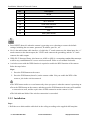
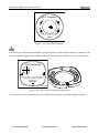
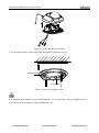
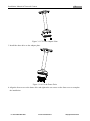
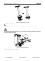
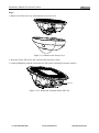
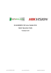
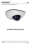
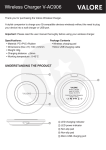
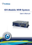
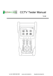
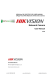
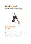
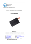
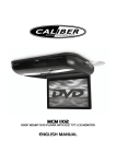
72 Installation Manual of Network Camera 3.9 Type IX Dome Camera 3.9.1 Camera Description 1 6 2 3 4 7 8 Figure 3-104 Overview (1) Figure 3-105 Overview (2) Table 3-11 Physical Description No. Description 1 Front Cover 2 Dome Drive 3 Micro SD Card Slot 4 Network Cable 5 Lens Lo-Call 1890 866 900 www.cctvireland.ie [email protected] 73 Installation Manual of Network Camera No. Description 6 7 8 9 IR LED Power Cable Audio/Alarm Cables Wi-Fi Antenna 10 Serial Port Interface 11 Hex Screw 12 MIC 13 RESET/WPS Button Press RESET about 10s when the camera is powering on or rebooting to restore the default settings, including the user name, password, IP address, port No., etc. No.8 is the audio/alarm cable interface, of which the “I” mark connects to the alarm input, the “o” mark connects to the alarm output, the “GND” mark connects the grounding, and the “A” mark connects the audio output. WPS (Wi-Fi Protected Setup, also known as AOSS or QSS) is a computing standard that attempts to allow easy establishment of a secure wireless network. Refer to user manual for details. A wireless router with the WPS function is required to enable the WPS function of the camera. Refer the steps below. Steps: 1. Press the WPS button on the router. 2. Press the WPS button (about 2s) on the camera within 120s you enable the WPS of the router to join in the wireless network. The WPS button works as a reset button only when you press it when the camera is powering on. Press the WPS button on the camera, and then press the WPS button on the router will establish a connection as well, and the expire time of WPS connection on the camera is 120s. The link indicator blinks if the wireless connection is succeeded. 3.9.2 Installation Steps: 1. Drill the screw holes and the cable hole in the ceiling according to the supplied drill template. Lo-Call 1890 866 900 www.cctvireland.ie [email protected] 74 Installation Manual of Network Camera Drill Template 1 1 1 1 Hole A:for cables routed through the ceiling Screw hole 1:for Mounting Base FRONT Figure 3-106 Type I Drill Template A different type of drill template might be provided because of the different batches of products. And also, the contained adapter plate matches with type II drill template differs as well. See figure below. Drill Template A 1 1 Hole A :for cables routed through the wall Screw hole1 :for Mounting Base FRONT Code:194101278 Figure 3-107 Type II Drill Template/Adapter Plate 2. Loosen the set screw on the front cover to disassemble the camera with the supplied Allen key. Lo-Call 1890 866 900 www.cctvireland.ie [email protected] 75 Installation Manual of Network Camera Figure 3-108 Disassemble the Camera 3. Fix the adapter plate to the ceiling with the supplied expansion screws. Adapter Plate Side Outlet Figure 3-109 Fix the Adapter Plate If the supplied drill template is type II drill template, you can skip step 3 and go straight to step 4. 4. Fix the dome drive with the supplied PM4x8 screws. Lo-Call 1890 866 900 www.cctvireland.ie [email protected] 76 Installation Manual of Network Camera Figure 3-110 Fix the Dome Drive 5. Connect the power cable, network cable, and the alarm/audio cable. Use a plier to remove the removable part and route the cables via side outlet (as shown in Figure 3-109) if no cable hole is drilled in step 1, and connect the corresponding cables. Figure 3-111 Remove the Removable Part 6. View the image via the web browser. 7. Slightly loosen the hex screw beside the WPS/RESET button to adjust the surveillance angle. 8. Use the supplied adjusting tool to adjust the pan [±30°], tilt [0~80°], and rotation direction [0~360°]. Lo-Call 1890 866 900 www.cctvireland.ie [email protected] 77 Installation Manual of Network Camera Pan Adjusting Tool Rotation Tilt Figure 3-112 3-axis Adjustment 9. Tighten the hex screw to fix the well-adjusted surveillance angle. 10. Align the front cover to the dome drive and tighten the set screws on the front cover to complete the installation. Figure 3-113 Install the Front Cover Ceiling Mounting with a Gang Box Steps: 1. Fix the adapter plate to the gang box with the supplied PM4x8 screws. Figure 3-114 Fix the Adapter Plate Lo-Call 1890 866 900 www.cctvireland.ie [email protected] 78 Installation Manual of Network Camera 2. Fix the dome drive to the adapter plate with the supplied PM4x8 screws. Figure 3-115 Fix the Dome Drive 3. Connect the power cable, network cable, and the alarm/audio cables. 4. Align the front cover to the dome drive and tighten the set screws on the front cover to complete the installation. Figure 3-116 Install the Front Cover Ceiling Bracket Mounting Steps: 1. Install the bracket to the ceiling with the supplied screws in the ceiling bracket package. The matched ceiling bracket model is DS-1271ZJ-120, and you need to purchases it separately if ceiling bracket mounting is adopted. 2. Fix the adapter plate to the ceiling bracket with the supplied PM4x8 screws. Lo-Call 1890 866 900 www.cctvireland.ie [email protected] 79 Installation Manual of Network Camera Figure 3-117 Fix the Adapter Plate 3. Install the dome drive to the adapter plate. Figure 3-118 Fix the Dome Drive 4. Align the front cover to the dome drive and tighten the set screws on the front cover to complete the installation. Lo-Call 1890 866 900 www.cctvireland.ie [email protected] 80 Installation Manual of Network Camera Figure 3-119 Install the Front Cover Wall Bracket Mounting Steps: 1. Install the wall bracket to the wall with the supplied screws in the wall bracket package. The matched ceiling bracket model is DS-1272ZJ-120B, and you need to purchases it separately if wall bracket mounting is adopted. Figure 3-120 Install Wall Bracket 2. Fix the adapter plate to the wall bracket. Lo-Call 1890 866 900 www.cctvireland.ie [email protected] 81 Installation Manual of Network Camera Figure 3-121 Fix the Adapter Plate 3. Fix the dome drive to the wall bracket with the supplied screws. Figure 3-122 Fix the Camera 4. Align the front cover to the dome drive and tighten the set screws on the front cover to complete the installation. Figure 3-123 Install the Front Cover Install the Micro SD Card This series of camera supports local storage, please refer to the following steps to install the micro SD card. Lo-Call 1890 866 900 www.cctvireland.ie [email protected] 82 Installation Manual of Network Camera Steps: 1. Remove the front cover by loosening the set screws on it. Figure 3-124 Remove the Front Cover 2. Insert the micro SD card to the card slot until you hear a click. 3. (Optional)Slightly push the inserted micro SD card to uninstall it from the camera. Mirco SD Card Figure 3-125 Install and Uninstall Micro SD Card Lo-Call 1890 866 900 www.cctvireland.ie [email protected]