1
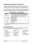
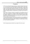
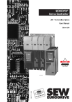
DeviceNet
Communication Manual
Soft-Starter
Series: SSW-07/SSW-08
Language: English
Document: 10000046963 / 00
03/2008
Summary
ABOUT THIS MANUAL ................................................................................................................................................ 5
ABBREVIATIONS AND DEFINITIONS .............................................................................................................................. 5
NUMERICAL REPRESENTATION ...................................................................................................................................... 5
DOCUMENTS ................................................................................................................................................................... 5
1
INTRODUCTION TO THE DEVICENET COMMUNICATION ....................................................................... 6
1.1
CAN ................................................................................................................................................................... 6
Data Frame............................................................................................................................................. 6
Remote Frame ....................................................................................................................................... 6
Access to the Network ........................................................................................................................ 6
Error Control .......................................................................................................................................... 6
CAN and DeviceNet ............................................................................................................................. 6
1.2 DEVICENET ......................................................................................................................................................... 7
1.2.1 Introduction ............................................................................................................................................ 7
1.2.2 Physical Layer ........................................................................................................................................ 7
1.2.3 Data Link Layer..................................................................................................................................... 8
1.2.4 Network and Transport Layer ......................................................................................................... 8
1.2.5 Application Layer – CIP Protocol ..................................................................................................... 8
1.2.6 Configuration File................................................................................................................................. 9
1.2.7 Communication Modes ....................................................................................................................... 9
1.2.8 Set of Predefined Master/Slave Connections ........................................................................... 10
1.1.1
1.1.2
1.1.3
1.1.4
1.1.5
2
ACCESSORY KIT ................................................................................................................................................... 11
2.1
CAN INTERFACE ............................................................................................................................................... 11
KFB-DN SSW-07/SSW-08 Drive Access Kit ................................................................................ 11
Connector Pinout ................................................................................................................................ 11
Power Supply ....................................................................................................................................... 11
CONNECTION WITH THE NETWORK ................................................................................................................. 11
STATUS INDICATION ........................................................................................................................................ 12
MODULE CONFIGURATION .............................................................................................................................. 12
ACCESS TO THE PARAMETERS ........................................................................................................................... 13
2.1.1
2.1.2
2.1.3
2.2
2.3
2.4
2.5
3
SOFT-STARTER PARAMETERIZATION ........................................................................................................... 14
3.1 SYMBOLS FOR PROPERTY DESCRIPTION .......................................................................................................... 14
P090 – CAN CONTROLLER STATUS ........................................................................................................................... 14
P091 – DEVICENET NETWORK STATUS ...................................................................................................................... 14
P092 – DEVICENET MASTER STATUS ......................................................................................................................... 15
P093 – RECEIVED CAN TELEGRAM COUNTER ........................................................................................................... 15
P094 – TRANSMITTED CAN TELEGRAM COUNTER .................................................................................................... 15
P095 – BUS OFF ERROR COUNTER ............................................................................................................................ 15
P096 – LOST CAN MESSAGE COUNTER .................................................................................................................... 15
P220 – LOCAL/REMOTE SELECTION SOURCE ........................................................................................................ 15
P229 – LOCAL COMMAND SELECTION ....................................................................................................................... 15
P230 – REMOTE COMMAND SELECTION .................................................................................................................... 15
P331 – CAN ADDRESS ............................................................................................................................................... 16
P332 – CAN BAUD RATE ........................................................................................................................................... 16
P333 – BUS OFF RESET............................................................................................................................................... 16
P335 – DEVICENET I/O INSTANCES .......................................................................................................................... 16
P348 – FIELDBUS COMMUNICATION ERROR ACTION ............................................................................................... 19
P336 – DEVICENET READING WORD #2 .................................................................................................................. 20
P337 – DEVICENET READING WORD #3 .................................................................................................................. 20
P338 – DEVICENET READING WORD #4 .................................................................................................................. 20
P339 – DEVICENET READING WORD #5 .................................................................................................................. 20
P340 – DEVICENET READING WORD #6 .................................................................................................................. 20
P341 – DEVICENET READING WORD #7 .................................................................................................................. 20
P342 – DEVICENET WRITING WORD #2 .................................................................................................................. 20
P343 – DEVICENET WRITING WORD #3 .................................................................................................................. 20
2
P344 – DEVICENET WRITING WORD #4 .................................................................................................................. 20
P345 – DEVICENET WRITING WORD #5 .................................................................................................................. 20
P346 – DEVICENET WRITING WORD #6 .................................................................................................................. 20
P347 – DEVICENET WRITING WORD #7 .................................................................................................................. 20
4
ERRORS RELATED TO THE DEVICENET COMMUNICATION................................................................... 21
E33 – CAN INTERFACE WITHOUT POWER SUPPLY .................................................................................................... 21
E34 – BUS OFF ............................................................................................................................................................ 21
E36 – IDLE MASTER ..................................................................................................................................................... 21
E37 – DEVICENET CONNECTION TIMEOUT ................................................................................................................ 22
3
About this Manual
About this Manual
This manual provides the necessary information for the operation of the SSW-07/SSW-08 Soft-Starter using the
DeviceNet protocol. This manual must be used together with the SSW-07/SSW-08 user manual.
Abbreviations and Definitions
ASCII
CAN
CIP
PLC
HMI
ODVA
American Standard Code for Information Interchange
Controller Area Network
Common Industrial Protocol
Programmable Logic Controller
Human-Machine Interface
Open DeviceNet Vendor Association
Numerical Representation
Decimal numbers are represented by means of digits without suffix. Hexadecimal numbers are represented with the
letter ‘h’ after the number.
Documents
The DeviceNet Protocol for the SSW-07/SSW-08 has been developed based on the following specifications and
documents:
Document
CAN Specification
Volume One
Common Industrial Protocol (CIP) Specification
Volume Three
DeviceNet Adaptation of CIP
Version Source
2.0
CiA
3.2
ODVA
1.4
ODVA
In order to obtain this documentation, consult ODVA, which is nowadays the organization that keeps, publishes and
updates the information related to the DeviceNet network.
5
1 Introduction to the DeviceNet Communication
In order to operate the SSW-07/SSW-08 Soft-Starter in a DeviceNet network, it is necessary to know the manner the
communication is performed. Therefore, this section brings a general description of the DeviceNet protocol
operation, containing the functions used by the SSW-07/SSW-08. Refer to the DeviceNet documentation indicated
above for a detailed description of the protocol.
1.1 CAN
DeviceNet is a network based on CAN, i.e., it uses CAN telegrams for exchanging data in the network.
The CAN protocol is a serial communication protocol that describes the services of layer 2 of the ISO/OSI model
(data link layer)1. This layer defines the different types of telegrams (frames), the error detection method, the
validation and arbitration of messages.
1.1.1 Data Frame
CAN network data is transmitted by means of a data frame. This frame type is composed mainly by an 11 bit2
identifier (arbitration field), and by a data field that may contain up to 8 data bytes.
Identifier
11 bits
byte 0
byte 1
byte 2
8 data bytes
byte 3 byte 4
byte 5
byte 6
byte 7
1.1.2 Remote Frame
Besides the data frame, there is also the remote frame (RTR frame). This type of frame does not have a data field,
but only the identifier. It works as a request, so that another network device transmits the desired data frame.
1.1.3 Access to the Network
Any device in a CAN network can make an attempt to transmit a frame to the network in a certain moment. If two
devices try to access the network simultaneously, the one that sends the message with the highest priority will be
able to transmit. The message priority is defined by the CAN frame identifier, the smaller the value of this identifier,
the higher the message priority. The telegram with the identifier 0 (zero) is the one with the highest priority.
1.1.4 Error Control
The CAN specification defines several error control mechanisms, which makes the network very reliable and with a
very low undetected transmission error rate. Every network device must be able to identify the occurrence of these
errors, and to inform the other elements that an error has been detected.
A CAN network device has internal counters that are incremented every time a transmission or reception error is
detected, and are decremented when a telegram is successfully transmitted or received. If a considerable amount of
errors occurs, the device can be led to the following states:
; Warning: when the counter exceeds a defined limit, the device enters the warning state, meaning the
occurrence of a high error rate.
; Error Passive: when this value exceeds a higher limit, the device enters the error passive state, and it stops
acting in the network when detecting that another device sent a telegram with an error.
; Bus Off: finally, we have the buss off state, in which the device will not send or receive telegrams any more.
1.1.5 CAN and DeviceNet
Only the definition of how to detect errors, create and transmit a frame, are not enough to define a meaning for the
data transmitted via the network. It is necessary to have a specification that indicates how the identifier and the data
must be assembled and how the information must be exchanged. Thus, the network elements can interpret the
transmitted data correctly. In that sense, the DeviceNet specification defines exactly how to exchange data among
the devices and how every one must interpret these data.
1
In the CAN protocol specification, the ISO11898 standard is referenced as the definition of the layer 1 of this model (physical layer).
The CAN 2.0 specification defines two data frame types, standard (11 bit) and extended (29 bit). For the SSW-07/08 DeviceNet protocol, only
the standard frames are accepted.
2
6
There are several other protocols based on CAN, as CANopen, J1939, etc., which do also use CAN frames for the
communication. However, those protocols cannot be used together in the same network.
1.2 DeviceNet
The next sections present, in a succinct form, the DeviceNet protocol.
1.2.1 Introduction
Introduced in 1994, DeviceNet is an implementation of the Common Industrial Protocol (CIP) for industrial
communication networks. Developed originally by Allen-Bradley, it had its technology transferred to the ODVA that,
since then, keeps, publishes and promotes DeviceNet and other networks based on the CIP3 protocol. Furthermore,
it uses the Controller Area Network (CAN) protocol for the data link and access to the medium, layers 2 and 1 of
the OSI/ISO model, respectively.
Used mainly for the connection of industrial controllers and I/O devices, the protocol follows the model producerconsumer, supports multiple communication modes and has priority between messages.
It is a system that can be configured to operate in master-slave architecture as well as in a distributed point-to-point
architecture. Besides, it defines two kinds of messages, I/O (process data) and explicit (configuration and parameter
setting). It also has mechanisms to detect duplicated addresses and for node isolation in case of critical faults.
A DeviceNet network can have up to 64 devices, addressed from 0 to 63. Any of them can be used. There is no
restriction, although the 63 should be avoided because it is usually used for commissioning purposes.
1.2.2 Physical Layer
DeviceNet uses a network topology of the trunk/derivation type that allows the signal wiring as well as the power
wiring to be present in the same cable. This power is supplied by a power supply connected directly to the network,
which feeds the CAN transceivers of the nodes, and has the following characteristics:
; 24Vdc;
; DC output isolated from the AC input;
; Current capacity compatible with the installed equipment.
The used Baud rate depends on the size (cable length) of the network, as showed in the table below.
Baud Rate
125kbps
250kbps
500kbps
Network
Size
500m
250m
100m
Derivation
Maximum
Total
156m
6m
78m
39m
Table 1.1 - Network size x Baud rate
In order to avoid reflections in the line, it is recommended the installation of termination resistors at the line
extremes, because the absence of them may cause intermittent errors. This resistor must have the following
characteristics, according to the protocol specification:
; 121Ω;
; 0,25W;
; 1% tolerance.
For DeviceNet, several types of connectors can be used, sealed ones as well as open ones. The definition of the
type to be used depends on the application and on the equipment operation environment. The SSW-07/SSW-08
uses a 5 wire plug-in connector, and its pinout is showed in the section 2. For a complete description of the
connectors used with DeviceNet, consult the protocol specification.
3 CIP actually represents a family of networks. DeviceNet, EtherNet/IP and ControlNet use CIP in the application layer. The difference among
them is primordially in the data link and physical layers.
7
1.2.3 Data Link Layer
The DeviceNet data link layer is defined by the CAN specification, which defines two possible states; dominant
(logic level 0) and recessive (logic level 1). A node can bring the network to the dominant state if it transmits any
information. Thus, the bus will only be in the recessive state if there where no transmitting nodes in the dominant
state.
CAN uses the CSMA/NBA to access the physical medium. This means that a node, before transmitting, must verify if
the bus is free. In case it is, then the node can initiate the transmission of its telegram. In case it is not, then the
node must await. If more than one node access the network simultaneously, a priority mechanism takes action to
decide which one will have priority over the others. This mechanism is not destructive, i.e., the message is preserved
even if there is a collision between two or more telegrams.
CAN defines four types of telegrams (data, remote, overload and error). Among them, DeviceNet uses only the
data frame and the error frame.
Data is moved using the data frame. This frame structure is showed in the
Figure 1.1.
Errors, however, are indicated by means of the error frames. CAN has a very robust error verification and
confinement. This assures that a node with problems does not impair the communication in the network.
1 bit
ACK Delimiter
7 bits
≥ 3 bits
Interframe Space
1 bit
End of Frame
1 bit
ACK Slot
15 bits
CRC Sequence
0-8 bytes
Data Field
6 bits
Control Field
1 bit
RTR bit
11 bits
Identifier
1 bit
Start of Frame
Interframe
Space
CRC Delimiter
For a complete description of the errors, consult the CAN specification.
Figure 1.1 – CAN data frame
1.2.4 Network and Transport Layer
DeviceNet requires that a connection be established before data exchange with the device takes place. In order to
establish this connection each DeviceNet node must implement the Unconnected Message Manager (UCMM) or
the Group 2 Unconnected Port. These two allocation mechanisms use messages of the explicit type to establish a
connection, which will then be used for process data exchange between one node and the other. This data
exchange uses messages of the I/O type (refer to item 1.2.7).
The DeviceNet telegrams are classified in groups, which define specific functions and priorities. Those telegrams use
the identifier field (11 bits) of the CAN data frame to uniquely identify each one of the messages, thus assuring the
CAN priority mechanism.
A DeviceNet node can be a client, a server or both. Furthermore, clients and servers can be producers and/or
consumers of messages. In a typical client node, for instance, its connection will produce requests and will consume
answers. Other client or server connections will only consume messages. In other words, the protocol allows several
connection possibilities among the devices.
The protocol also has a resource for detection of nodes with duplicated addresses (Mac ID). Avoiding that
duplicated addresses occur is, in general, more efficient than trying to locate them later.
1.2.5 Application Layer – CIP Protocol
In the application layer, DeviceNet uses the Common Industrial Protocol (CIP). It is a protocol strictly orientated to
objects, used also by ControlNet and EtherNet/IP. In other words, it is independent from the physical medium and
from the data link layer. The Figure 1.2 presents the structure of this protocol.
The CIP has two main purposes:
; Transport of I/O devices control data.
; Transport of configuration and diagnosis information of the system being controlled.
8
A DeviceNet node (master or slave) is then molded by a set of CIP objects, which encapsulate data and services,
thus determining its behavior.
There are obligatory objects (each device must have) and optional objects. Optional objects are those that mold the
device according to the category (called profile) to which they belong, as: AC/DC drive, bar code reader or
pneumatic valve. For being different, each one of these will contain a group of also different objects.
For more information refer to the DeviceNet specification. It presents the complete list of devices already
standardized by the ODVA, as well as the objects that compose them.
1.2.6 Configuration File
Every DeviceNet node has a configuration file associated4 . This file contains important information about the
device operation and must be registered in the network configuration software.
Figure 1.2 - CIP protocol structure in layers
1.2.7 Communication Modes
The DeviceNet protocol presents two basic types of messages, I/O and explicit. Each one of them is adequate to a
specific kind of data, as described below:
; I/O: It is a kind of synchronous telegram dedicated to the movement of priority data between one producer
and one or more consumers. They are divided according to the data exchange method. The main types are:
-
Polled: It is a communication method where the master sends one telegram to each of the slaves of its
list (scan list). As soon as receiving the request, the slave responds promptly to the request from the
master. This process is repeated until all be consulted, restarting the cycle.
-
Bit-strobe: It is a communication method where the master sends to the network a telegram containing
8 data bytes. Each bit from those 8 bytes represents a slave that, if addressed, responds according to
the programmed.
4 Known as EDS file.
9
-
Change of State: It is a communication method where the data exchange between master and slave
occurs only when changes in the monitored/controlled values happened, until a certain time limit.
When this limit is reached, the transmission and reception will occur even if there were no changes.
The configuration of this time variable is done in the network configuration program.
-
Cyclic: It is another communication method very similar to the previous one. The only difference stays
in the production and consume of messages. In this type, every data exchange occurs in regular time
intervals, whether or not they had been changed. This time period is also adjusted in the network
configuration software.
; Explicit: It is a kind of general purpose telegram and without priority. It is mainly used for asynchronous tasks
like the parameter settings and the configuration of the equipment.
1.2.8 Set of Predefined Master/Slave Connections
DeviceNet uses fundamentally a point-to-point message model. However, it is quite common to use a predefined
communication model based on the master/slave mechanism.
This model uses a simplified message movement of the I/O type, very common in control applications. An
advantage of this method is that the necessary requests to run it are generally less than for the UCMM. Even simple
devices with limited resources (memory, 8 bit processor) are capable of executing the protocol.
10
2 Accessory Kit
In order to make the DeviceNet communication possible with the SSW-07/SSW-08 Soft-Starter, it is necessary to
use the CAN communication kit described next. Information on the installation of this module in the Soft-Starter can
be obtained in the guide that comes with the kit.
2.1 CAN Interface
2.1.1 KFB-DN SSW-07/SSW-08 Drive Access Kit
; WEG part number: 10561140.
; Composed by the CAN communication module (drawing at the
left) and a mounting guide.
; The interface is electrically isolated and with differential signal,
which grants more robustness against electromagnetic
interference.
; External 24V supply via the DeviceNet network cable.
; Remote HMI connection possibility (XC40 connector).
2.1.2 Connector Pinout
The CAN communication module has a 5-wire plug-in connector with the following pinout:
Pin
1
2
3
4
5
Name
VCAN_L
Shield
CAN_H
V+
Function
Power supply negative pole
CAN_L communication signal
Cable shield
CAN_H communication signal
Power supply positive pole
Table 2.1 – CAN interface XC5 connector pinout
2.1.3 Power Supply
The SSW-07/SSW-08 CAN interface needs an external power supply between the pins 1 and 5 of the network
connector. In order to avoid problems of potential difference among the network devices, it is recommended that
the network be supplied at only one point, and that the power supply be taken to all of the devices trough the
cable. If more than one power supply is necessary, they must be referenced to the same point. The individual
consumption and input voltage data are presented in the next table.
Power Supply (Vdc)
Maximum
Recommended
30
24
Current (mA)
Average
Maximum
30
60
Minimum
11
Table 2.2 – CAN/DeviceNet interface power supply characteristics
2.2 Connection with the Network
For the connection of the Soft-Starter using the active DeviceNet interface the following points must be observed:
; The use of cables specific for CAN/DeviceNet networks is recommended.
; Grounding of the cable shield at only one point, thus avoiding current loops. This point is usually at the power
supply. If there is more than one power supply, only one of them must be connected to the protective earth.
; The termination resistors must be installed only at the extremes of the main bus, even if there are derivations.
11
; The network power supply must be able to deliver enough current to feed all the equipment transceivers. The
SSW-07/SSW-08 DeviceNet module consumes approximately 30mA.
2.3 Status Indication
Status/error identification of the equipment in the DeviceNet network is done through messages on the display and
bicolored MS (Module Status) and NS (Network Status) LEDs located in the product’s HMI.
The bicolored MS LED indicates the status of the device itself:
Status
Off
Solid Green
Intermittent Red/Green
Description
No supply
Operational and in normal conditions
Running the auto-test during start
However, the bicolored NS LED indicates the status of the DeviceNet network:
Status
Off-line
Intermittent Green
Solid Green
Intermittent Red
Solid Red
Intermittent Red/Green
Description
Device without power supply or not on-line.
Communication cannot be established.
Device online but not connected. The slave
has successfully completed the MacID
verification procedure. This means that the
configured baud rate is correct (or it has been
detected correctly in case of autobaud) and
that there are no other network nodes with the
same address. However, there is still no
communication with the master in this stage.
The device is operational and in normal
conditions. The master has allocated a set of
I/O type connections with the slave. In this
stage, the effective exchange of data by
means of I/O type connections occurs.
One or more I/O type connections have
expired.
It indicates that the slave was not able to enter
the network due to addressing problems or
due to the occurrence of bus off. Make sure
the configured address is not already being
used by another device and verify if the
chosen baud rate is correct.
The equipment is running the auto-test. This
occurs during the start.
2.4 Module Configuration
In order to configure the DeviceNet module follow the steps indicated below:
With the Soft-Starter powered off install the DeviceNet module at the equipment front cover.
Make sure it is fitted in properly.
Power up the Soft-Starter.
Adjust the Soft-Starter network address through the parameter P331.
- Valid values: 0 to 63.
; Set the baud rate in P332. Valid values:
- 0 = 125kbps
- 1 = 250kbps
- 2 = 500kbps
- 3 = Autobaud
; Configure the most suitable I/O instance for the application at the parameter P335 (this choice will impact the
number of words exchanged with the network master). The very same number of words must be adjusted at the
network master. Finally, program a value different from 0 in the parameters P336 to P347 (refer to the section
3).
;
;
;
;
12
- Valid values: 0 to 7.
Cycle the power of the SSW-07/SSW-08, so that the changes become effective.
Connect the network cable to the module.
Register the configuration file (EDS file) in the network configuration software.
Add the SSW-07/SSW-08 to the scan list of the master.
In the network configuration software, choose a method of data exchange with the master, i.e., polled, change
of state or cyclic. The SSW-07/SSW-08 DeviceNet module supports all these I/O data types, besides the
explicit (acyclic data).
; If everything is configured correctly the parameter P091 will indicate the “Online Not Connected” or “Online
Connected” state. Observe also the parameter that indicates the network master status, P092. There will only
be effective data exchange when the master status is Run.
;
;
;
;
;
Refer to the section 3 for more information on the parameters mentioned above.
2.5 Access to the Parameters
After the EDS file registration in the network configuration software, the user will get access to the equipment
complete parameter list, which can be accessed via explicit messages.
This means that it is possible to perform the drive parameterization and configuration through the network
configuration software.
In order to get details on the application of this resource, refer to the network master programming documentation
(PLC, PC, etc.).
13
3 Soft-Starter Parameterization
Next, only the SSW-07/SSW-08 Soft-Starter parameters related to the DeviceNet communication will be presented.
3.1 Symbols for Property Description
RO
CFG
Read-only parameter
Parameter that can be changed only with a stopped motor
P090 – CAN Controller Status
Adjustable
Range:
0 = Inactive
1 = Autobaud
2 = Active CAN interface
3 = Warning
4 = Error Passive
5 = Bus Off
6 = No Bus Power
Factory
Setting:
Properties: RO
Description:
It allows identifying if the CAN interface board is properly installed and if the communication presents errors.
Options
0 = Inactive
1 = Autobaud
2 = Active CAN
interface
3 = Warning
4 = Error Passive
5 = Bus Off
6 = No Bus Power
Description
Inactive CAN interface. It occurs when the Soft-Starter
does not have the CAN interface installed.
The CAN interface is executing Autobaud routines.
CAN interface is active and without errors.
The CAN controller has reached the warning state.
The CAN controller has reached the error passive state.
The CAN controller has reached the bus off state.
The CAN interface does not have power supply between
the pins 1 and 5 of the connector.
Table 3.1 – Values for the parameter P090
P091 – DeviceNet Network Status
Adjustable
Range:
0 = Offline
1 = Online, Not Connected
2 = Online, Connected
3 = Timed-out Connection
4 = Connection Failure
5 = Auto-baud
Factory
Setting:
-
Properties: RO
Description:
It indicates the status of the DeviceNet network. The next table presents a brief description of those states.
Status
Description
Offline
Device without power supply or not online. Communication cannot be established.
Online, Not Connected
Device online, but not connected. The slave has successfully completed the MacID
verification procedure. This means that the configured baud rate is correct (or it has been
detected correctly in case of autobaud) and that there are no other network nodes with the
same address. However, there is no communication with the master yet in this stage.
The device is operational and in normal conditions. The master has allocated a set of I/O
type connections with the slave. In this stage the effective exchange of data by means of I/O
type connections occurs.
One or more I/O type connections have expired.
Online, Connected
Timed-out Connection
Connection Failure
Autobaud
It indicates that the slave was not able to enter the network due to addressing problems or
due to the occurrence of bus off. Make sure the configured address is not used by another
device, verify if the chosen baud rate is correct and make sure there are no installation
problems.
The equipment is executing the autobaud mechanism routine.
Table 3.2 – Values for the parameter P091
14
P092 – DeviceNet Master Status
Adjustable
Range:
0 = Run
1 = Idle (Prog)
Factory
Setting:
-
Properties: RO
Description:
It indicates the DeviceNet network master status. It may be in operation mode (Run) or in configuration mode
(Prog).
When in Run, reading and writing telegrams are normally processed and updated by the master. When in Prog,
only the reading telegrams from the slaves are updated by the master. Writing, in this case, remains disabled.
P093 – Received CAN Telegram Counter
Adjustable
Range:
0 to 9999
Factory
Setting:
-
Properties: RO
Description:
This parameter works as a cyclic counter that is incremented every time a CAN telegram is received. It gives a
feedback to the operator if the device is able to communicate with the network. This counter is reset every time the
Soft-Starter is switched off, a reset is performed or when the maximum limit of the parameter is reached.
P094 – Transmitted CAN Telegram Counter
Adjustable
Range:
0 to 9999
Factory
Setting:
-
Properties: RO
Description:
This parameter works as a cyclic counter that is incremented every time a CAN telegram is transmitted. It gives a
feedback to the operator if the device is able to communicate with the network. This counter is reset every time the
Soft-Starter is switched off, a reset is performed or when the maximum limit of the parameter is reached.
P095 – Bus Off Error Counter
Adjustable
Range:
0 to 9999
Factory
Setting:
-
Properties: RO
Description:
It is a cyclic counter that indicates the number of times the Soft-Starter entered the bus off state in the CAN network.
This counter is reset every time the Soft-Starter is switched off, a reset is performed or when the maximum limit of the
parameter is reached.
P096 – Lost CAN Message Counter
Adjustable
Range:
0 to 9999
Factory
Setting:
-
Properties: RO
Description:
It is a cyclic counter that indicates the number of messages received by the CAN interface that could not be
processed by the Soft-Starter. In case that the number of lost messages is frequently incremented, it is recommended
to reduce the baud rate used in the CAN network. This counter is reset every time the Soft-Starter is switched off, a
reset is performed or when the maximum limit of the parameter is reached.
P220 – LOCAL/REMOTE Selection Source
P229 – Local Command Selection
P230 – Remote Command Selection
These parameters are used in the configuration of the command source for SSW-07/SSW-08 local and remote
modes. In order that the Soft-Starter be controlled through the DeviceNet interface, the options “Fieldbus” available
in these parameters must be selected.
15
The detailed description of these parameters is found in the SSW-07/SSW-08 Programming Manual.
P331 – CAN Address
Adjustable
Range:
0 to 63
Factory 63
Setting:
Description:
It allows programming the address used for the Soft-Starter CAN communication. It is necessary that each device in
the network has an address different from the others.
If this parameter is changed, it becomes valid only after cycling the power of the Soft-Starter.
P332 – CAN Baud Rate
Adjustable
Range:
0 = 125 kbps
1 = 250 kbps
2 = 500 Kbps
3 = Autobaud
Factory 3
Setting:
Description:
It allows programming the desired value for the CAN interface baud rate, in bits per second. This rate must be the
same for all the devices connected to the network. When the option “Autobaud” is selected, the SSW-07/SSW-08
will adjust itself automatically to the actual network baud rate.
In order that this mechanism works it is mandatory that two or more devices be actively communicating in the
network.
After a successful detection, the baud rate parameter (P332) changes automatically to the detected rate. In order to
execute the autobaud function again, it is necessary to change the parameter P332 to the “Autobaud” option.
If this parameter is changed, it becomes valid only after cycling the power of the Soft-Starter.
P333 – Bus Off Reset
Adjustable
Range:
0 = Manual
1 = Automatic
Factory 1
Setting:
Description:
It allows programming the Soft-Starter behavior when detecting a bus off error in the CAN interface:
Options
0 = Manual Reset
1= Automatic Reset
Description
If bus off occurs, the E33 error will be indicated on the HMI, the action
programmed in parameter P348 will be executed and the communication
will be disabled. In order that the Soft-Starter communicates again through
the CAN interface, it will be necessary to cycle the power supply.
If bus off occurs, the communication will be reinitiated automatically and
the error will be ignored. In this case the error will not be indicated on the
HMI and the Soft-Starter will not execute the action programmed in P348.
Table 3.2 – Values for the parameter P333
P335 – DeviceNet I/O Instances
Adjustable
Range:
0 = ODVA (1 byte)
1 = WEG Specific 1W (1 word)
2 = WEG Specific 2W (2 words)
3 = WEG Specific 3W (3 words)
4 = WEG Specific 4W (4 words)
5 = WEG Specific 5W (5 words)
6 = WEG Specific 6W (6 words)
7 = WEG Specific 7W (7 words)
Factory 0
Setting:
Description:
It allows selecting the Assembly class instance for the I/O type communication. These instances represent the user
interface with the SSW-07/SSW-08 Soft-Starter. Each one presents the control and monitoring data in one manner.
It is up to the user to choose which option is the best for the application.
16
The SSW-07/SSW-08 Soft-Starter has eight setting options. The first of them follow the ODVA Soft-Starter Starter
Device profile. The other seven represent specific WEG words.
The tables presented next describe each of these control and monitoring words.
If this parameter is changed, it becomes valid only after cycling the power of the Soft-Starter.
0 = Data format for the ODVA instances (1 byte):
These instances represent the simplest operation interface of a device according to the ODVA Soft-Starter Starter
Device profile. The data mapping is showed below.
Monitoring (Input)
Bit
7
Bit
6
Bit
5
Bit
4
Bit
3
Bit
7
Bit
6
Bit
5
Bit
4
Bit
3
Bit
2
Bit
1
60
Bit
0
Faulted
Running1
Instance
Control (Output)
Bit
2
Bit
1
3
Bit
0
Run1
Fault Reset
Instance
1 = Data Format for the WEG Specific 1W (1 word) instances:
Called WEG Specific 1W, these instances present the simplest equipment operation interface according to the WEG
profile. The data mapping is showed below.
7
In DC Braking
In Remote Mode
In Deceleration
6
5
4
3
2
1
0
Motor Running
8
General Enabling
9
In Acceleration
10
At Current Limit
11
At Full Voltage
12
Reverting Speed
Direction
13
Reverse Direction
14
With Closed
By-pass
Function
15
Power Section
Supply
Bits
With Error
Monitoring (Input)
17
Bits (Byte 0 and 1)
Bit 0
Motor Running
Bit 1
General Enabling
Bit 2
Values
0: The motor is stopped
1: The motor is running
0: The Soft-Starter is not enabled
1: The Soft-Starter is enabled and ready to run the motor
Bit 3
In Acceleration
Bit 4
At Current Limit
Bit 5
At Full Voltage
Bit 6
0: It is not accelerating
1:During the entire acceleration
0: It is not at current limit
1: At current limit
0: Motor without full voltage
1: With the motor at full voltage
Bit 7
In Deceleration
Bit 8
In Remote Mode
Bit 9
In DC Braking
Bit 10
Reverting Speed Direction
Bit 11
Speed Direction
Bit 12
With Closed By-pass
Bit 13
0: It is not decelerating
1: During the entire deceleration
0: Local
1: Remote
0: It is not in DC Braking
1: During the DC Braking
0: It is not reverting the speed direction
1: During the speed direction reversion
0: Forward
1: Reverse
0: The by-pass is open
1: With closed by-pass
Bit 14
Power Section Supply
Bit 15
With Error
0: Without supply at the power section
1: With supply at the power section
0: Without error
1: With error
Reserved
Reserved
Reserved
13
12
11
10
9
8
7
6
Function
5
4
3
Bits (Bytes 0 and 1)
Bit 0
Start/Stop
Bit 1
General Enabling
Bit 2
Values
0: It stops the motor with the deceleration ramp
1: It starts the motor with the acceleration ramp
0: General disabling
1: General enabling
Bit 3
Speed Direction
Bits 4,5 and 6
0: Forward
1: Reverse
Bit 7
Reset
Bits 8 to 15
0: No function
0 ->1: If in a fault condition, then it executes the fault reset
2
1
0
General
Enabling
Start by
Acceleration
Ramp
14
Speed Direction
15
Error Reset
Bits
Goes to Remote
Mode
Control (Output)
Reserved
Reserved
Reserved
2 = Data Format for the WEG Specific 2W (2 words) instances:
3 = Data Format for the WEG Specific 3W (3 words) instances:
4 = Data Format for the WEG Specific 4W (4 words) instances:
5 = Data Format for the WEG Specific 5W (5 words) instances:
5 = Data Format for the WEG Specific 6W (6 words) instances:
5 = Data Format for the WEG Specific 7W (7 words) instances:
These instances have the same data format as the WEG Specific 1W. Besides the command and monitoring words
showed above, they make it possible to program up to 6 parameters of the equipment for reading and/or writing
via network.
18
Monitoring (Input)
Instance
150
16 Bit Words
Function
1
Monitoring
2
Contents of the parameter P336
3
Contents of the parameter P337
4
Contents of the parameter P338
5
Contents of the parameter P339
6
Contents of the parameter P340
7
Contents of the parameter P341
16 Bit Words
Function
1
Control
2
Contents of the parameter P342
3
Contents of the parameter P343
4
Contents of the parameter P344
5
Contents of the parameter P345
6
Contents of the parameter P346
7
Contents of the parameter P347
P335 Options
1
2
3
4
5
6
7
Control (Output)
Instance
100
P335 Options
1
2
3
4
5
6
7
P348 – Fieldbus Communication Error Action
Adjustable
Range:
0 = Error indication only
1 = Stop via Ramp
2 = General Disable
3 = Change to Local
Factory
1
Setting:
Description:
This parameter allows selecting which action must be executed by the Soft-Starter in case that a fieldbus
communication error is detected.
Options
0 = Error indication only
1 = Stop via Ramp
2 = General Disable
3 = Change to Local
Description
No action, besides the error indication, is taken and the
Soft-Starter remains in the existing status
A stop command with deceleration ramp is executed and
the motor stops according to the programmed
deceleration ramp
The Soft-Starter is disabled by removing the General
Enabling and the motor coasts to stop
The Soft-Starter commands change to the local mode
Table 3.3 – Values for the parameter P348
For the CAN interface used with the DeviceNet protocol, the following events are considered communication errors:
;
;
;
;
E33 error: CAN interface without power supply.
E34 error: bus off.
E36 error: Idle network master.
E37 error: timeout in one or more I/O connections has occurred.
The description of these errors is presented in the section 4.
19
In order that the executed action be effective, it is necessary that the Soft-Starter be programmed to be controlled
via the fieldbus interface. This programming is done by means of the parameters P220, P229 and P230.
P336
P337
P338
P339
P340
P341
–
–
–
–
–
–
DeviceNet
DeviceNet
DeviceNet
DeviceNet
DeviceNet
DeviceNet
Adjustable
Range:
Reading
Reading
Reading
Reading
Reading
Reading
Word
Word
Word
Word
Word
Word
#2
#3
#4
#5
#6
#7
0 to 999
Factory 0
Setting:
Properties: CFG
Description:
These parameters allow the user to program the reading of any other equipment parameter via the network. I.e.,
they contain the number of another parameter.
For instance, P336 = 5. In this case the content of P005 (line frequency) will be sent via network. In this manner, in
the network master memory position corresponding to the second reading word, the supply line frequency will be
read.
P342
P343
P344
P345
P346
P347
–
–
–
–
–
–
DeviceNet
DeviceNet
DeviceNet
DeviceNet
DeviceNet
DeviceNet
Adjustable
Range:
Properties:
Writing
Writing
Writing
Writing
Writing
Writing
0 to 999
Word
Word
Word
Word
Word
Word
#2
#3
#4
#5
#6
#7
Factory
0
Setting:
CFG
Description:
These parameters allow the user to program the writing of any other equipment parameter via the network. I.e.,
they contain the number of another parameter.
For instance, P342 = 102. In this case the content to be written in P0102 will be sent via network. In this manner,
the network master memory position corresponding to the second writing word must contain the value for P0102.
20
4 Errors Related to the DeviceNet Communication
E33 – CAN Interface Without Power Supply
Description:
It indicates that the CAN interface does not have power supply between connector pins 1 and 5.
Actuation:
In order that it be possible to send and receive telegrams through the CAN interface, it is necessary to supply
external power to the interface circuit.
If the absence of power supply at the CAN interface is detected, the communication will be disabled, the Soft-Starter
HMI will show E33 and the action programmed in P348 will be executed. If the power supply to the circuit is
reestablished, the error indication will be removed from the HMI and the CAN communication will be reinitiated.
Possible Causes/Correction:
; Measure if there is voltage between the pins 1 and 5 of the CAN interface connector.
; Verify if the power supply cables have not been changed or inverted.
; Make sure there is no contact problem in the cable or in the CAN interface connector.
E34 – Bus Off
Description:
The bus off error in the CAN interface has been detected.
Actuation:
If the number of reception or transmission errors detected by the CAN interface is too high, the CAN controller can
be taken to the bus off state, where it interrupts the communication and disables the CAN interface.
If the bus off error occurs, the CAN communication will be disabled, the error E34 will appear on the Soft-Starter
HMI and the action programmed in P348 will be executed. In order that the communication be reestablished, it will
be necessary to cycle the Soft-Starter power or remove the power supply from the CAN interface and apply it again,
so that the communication be reinitiated.
Possible Causes/Correction:
; Make sure there is no short-circuit in CAN circuit transmission cables.
; Verify if the cables have not been changed or inverted.
; Make sure that termination resistors with the correct value have been installed only at the extremes of the main
bus.
; Verify if the installation of the CAN network was done in an adequate manner.
E36 – Idle Master
Description:
It is the alarm that indicates that the DeviceNet network master is in the Idle mode.
Actuation:
It acts when the SSW-07/SSW-08 detects that the network master went to the Idle mode. In this mode, only the
variables read from the slave continue being updated in the memory of the master. None of the commands sent to
the slave is processed.
In this case E36 will be shown on the Soft-Starter HMI. It is necessary to get the master in the Run mode again
(normal equipment operation state) so that the communication be reestablished and the alarm be erased from the
HMI.
Possible Causes/Correction:
; Adjust the switch that commands the master operation mode for execution (Run) or set the correspondent bit in
the configuring word of the master software. In case of uncertainty, refer to the used master documentation.
21
E37 – DeviceNet Connection Timeout
Description:
It is the alarm that indicates that one or more DeviceNet I/O connections have expired.
Actuation:
It occurs when for any reason the master is not able to access information from the slave.
In this case E37 will be shown on the Soft-Starter HMI.
Possible Causes/Correction:
; Verify if the master is present in the network and if it is in the Run mode.
22