1
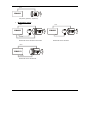
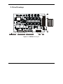
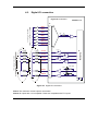
ISM4803 / ISM4803-CAN Version 1.2 Intelligent Servo Drive for Step, DC, Brushless DC and AC Motors Intelligent Servo Drive Technical Reference © Technosoft 2009 TECHNOSOFT ISM4803 / ISM4803-CAN Technical Reference P091.030.UM.1109 Technosoft S.A. Buchaux 38 CH-2022 Bevaix, NE Switzerland Tel.: +41 (0) 32 732 5500 Fax: +41 (0) 32 732 5504 e-mail: [email protected] http://www.technosoftmotion.com/ Read This First About This Manual This book is a technical reference manual for the ISM4803 intelligent servo drives. It describes the ISM4803 operation and provides basic information needed by the user to program the ISM4803 in the Technosoft Motion Language (TML) environment. Notational Conventions This document uses the following conventions: • • The Technosoft Motion Language will be referred to as TML TML variables, parameters or instructions are shown in special italic typeface. Here is a sample: SETIO#4 IN; UPD; Information about Cautions This book may contain cautions. CAUTION! THIS IS AN EXAMPLE OF A CAUTION STATEMENT. A CAUTION STATEMENT DESCRIBES A SITUATION THAT COULD POTENTIALLY CAUSE HARM TO YOU, OR TO THE ISM4803 INTELLIGENT SERVO DRIVE UNIT Related Documentation from Technosoft MotionChip™ II TML Programming (part no. P091.055.MCII.TML.UM.xxxx) describes in detail TML basic concepts, motion programming, functional description of TML instructions for high level or low level motion programming, communication channels and protocols. Also give a detailed description of each TML instruction including syntax, binary code and examples. MotionChip II Configuration Setup (part no. P091.055.MCII.STP.UM.xxxx) describes the MotionChip II operation and how to setup its registers and parameters starting from the user application data. This is a technical reference manual for all the MotionChip II registers, parameters and variables. © Technosoft 2009 III ISM4803 / ISM4803-CAN Technical Reference Help of the EasyMotion Studio software platform – describes how to use the EasyMotion Studio – the complete development platform for ISM4803 which support all new features added to revision H of firmware. It includes: motion system setup & tuning wizard, motion sequence programming wizard, testing and debugging tools like: data logging, watch, control panels, on-line viewers of TML registers, parameters and variables, etc. Help of the IPM Motion Studio software platform – describes how to use the IPM Motion Studio – the complete development platform for ISM4803. It includes: motion system setup & tuning wizard, motion sequence programming wizard, testing and debugging tools like: data logging, watch, control panels, on-line viewers of TML registries, parameters and variables, etc. If you Need Assistance … If you want to … Contact Technosoft at … Visit Technosoft online World Wide Web: http://www.technosoftmotion.com/ Receive general information or assistance (see Note) World Wide Web: http://www.technosoftmotion.com/ Email: [email protected] Ask questions about product operation or report suspected problems (see Note) Fax: (41) 32 732 55 04 Email: [email protected] Make suggestions about, or report errors in documentation (see Note) Mail: Technosoft SA Buchaux 38 CH-2022 Bevaix, NE Switzerland Note: You need to register your ISM4803 system, in order to get free assistance and support. Use the License No. on your Registration Card for IPM Motion Studio. © Technosoft 2009 IV ISM4803 / ISM4803-CAN Technical Reference Contents 1. Key Features 3 2. Supported Motor-Sensor Configurations 4 3. Drive Drawings 6 4. Connectors and Connection Diagrams 7 4.1. Connectors pinout 7 4.1.1. J1 Connector pinout 7 4.1.2. J2 Connector pinout 7 4.1.3. J3 Connector pinout 8 4.1.4. J7 Connector pinout 9 4.1.5. J9 Connector pinout 9 4.1.6. J10 Connector pinout 10 4.2. Digital I/O connection 11 4.3. Pulse & Direction inputs connections 12 4.4. Analog inputs connection 14 4.5. Brushless Motor connection 15 4.6. 2-phases Step Motor connection 16 4.7. 3-phases Step Motor connection 18 4.8. DC Motor connection 19 4.9. Single-ended encoder connection 20 4.10. Differential encoder connection 21 4.11. Hall connection 22 4.12. Linear Hall connection 23 4.13. Linear Hall Auto-Setup connection 24 4.14. Recommendations for feedback wiring 24 4.15. Supply connection 25 4.16. Serial RS-232 connection 26 4.17. CAN connection (only for ISM4803-CAN drive) 27 4.18. Master - Slave encoder connection 29 © Technosoft 2009 V ISM4803 / ISM4803-CAN Technical Reference 4.19. Jumpers and solder-joints 30 5. Electrical Specifications 33 6. ISM4803 LEDs 37 7. ISM4803 Dimensions 37 8. Connector Type and Mating Connectors 38 9. Scaling factors 39 9.1. Supply / DC-bus Voltage Measurement Scaling 39 9.2. Motor Currents Scaling 39 9.3. Motor Speed Scaling 40 9.4. Motor Position Scaling 40 10. Available Memory Areas © Technosoft 2009 41 VI ISM4803 / ISM4803-CAN Technical Reference 1. Key Features • • • • • • • • • • • • • • • • • • • • Continuous drive power: 150 W (48V, 3A) Logic supply: 5VDC; 600 mA Motor supply: 12-48V; 3A; 6A PEAK Motor output: 3 A RMS continuous (BLDC); 6A PEAK Digital Hall sensor interface (single-ended and open collector) Encoder interface (single-ended, open collector and differential) Linear Hall interface 4 general-purpose digital inputs 4 general-purpose digital outputs 6 dedicated digital inputs (Enable, Pulse, Dir, LSN, LSP, Auto) 2 dedicated digital outputs (Ready, Error) 2 analog inputs (REF, FDBK) RS-232 serial interface CAN-bus 2.0B interface 1.5K ´ 16 internal SRAM memory 8K ´ 16 E2ROM to store TML programs and data On-board thermal sensor HW / SW AxisID selection Operating ambient temperature: 0-40°C Hardware Protections: o Short-circuit on motor phases and short-circuit to ground o All I/Os are ESD protected © Technosoft 2009 3 ISM4803 / ISM4803-CAN Technical Reference 2. Supported Motor-Sensor Configurations ISM4803 supports the following configurations: • Brushless motor Motor Motor ISM4803 ISM4803 Encoder Encoder Hall Brushless motor with encoder and Hall Brushless motor with encoder Motor Motor ISM4803 ISM4803 Hall Linear Hall Brushless motor with Hall • Brushless motor with Linear Hall sensor Step motor Motor Motor ISM4803 ISM4803 Encoder Step motor (2phases) – Open loop © Technosoft 2009 Step motor (2phases) – Closed loop (with encoder on motor, or on load) 4 ISM4803 / ISM4803-CAN Technical Reference Motor ISM4803 Step motor (3phases) – Open loop • Brushed DC motor Motor ISM4803 Motor ISM4803 TG Tacho TG Tacho Encoder Brushed DC motor with tacho and encoder Brushed DC motor with tacho Motor ISM4803 Encoder Brushed DC motor with encoder © Technosoft 2009 5 ISM4803 / ISM4803-CAN Technical Reference 3. Drive Drawings J1 J3 J7 4x 3.2mm J9 (not mounted) J6 (not mounted) J2 J10 Figure 3.1. ISM4803 v1.2 layout © Technosoft 2009 6 ISM4803 / ISM4803-CAN Technical Reference 4. Connectors and Connection Diagrams CAUTION! 4.1. BEFORE THE CONNECTING / DISCONNECTING ANY OF THE SIGNALS PLEASE TURN OFF ALL POWER SUPPLIES. ELSE SEVER DAMAGE MAY OCCUR. Connectors pinout 4.1.1. J1 Connector pinout Pin Pin name Type Function/Alternate function/ Comments 1 +VMOT I Positive terminal of the 12–48VDC external power supply for motor 2 GND - Ground 3 +5VDC I Positive terminal of the +5VDC external power supply for logic 4.1.2. J2 Connector pinout Pin Pin name Type Function/Alternate function/ Comments 1 TXD O RS232 Data Transmission 2 GND - Ground 3 RXD I RS232 Data Reception © Technosoft 2009 7 ISM4803 / ISM4803-CAN Technical Reference 4.1.3. J3 Connector pinout Pin Pin name TML name Type Function/Alternate function/ Comments • Not used; Brushless motor 1 B- - O • Phase B-; 2-phases Step motor • Not used; 3-phases Step motor • Not used; DC Brushed motor • Phase A; Brushless motor 2 A/A+ - O • Phase A+; 2-phases Step motor • Phase A; 3-phases Step motor • Motor +; DC Brushed motor • Phase B; Brushless motor 3 B/A- - O • Phase A-; 2-phases Step motor • Phase B; 3-phases Step motor • Motor -; DC Brushed motor • Phase C; Brushless motor 4 C/B+ - O • Phase B+; 2-phases Step motor • Phase C; 3-phases Step motor • Not used; DC Brushed motor 5 +5VDC - O +5VDC output voltage (from J1 connector) 6 H1 - I Hall 1 (digital) 7 H2 - I Hall 2 (digital) 8 H3 - I Hall 3 (digital) 9 GND - - Ground 10 GND - - Ground © Technosoft 2009 8 ISM4803 / ISM4803-CAN Technical Reference 4.1.4. J7 Connector pinout Pin Pin name TML name Type Function/Alternate function/ Comments 1 GND - - Ground 2 +5VDC - O +5VDC output voltage (from J1 connector) 3 GND* - - Ground (if SJ6 is strapped) 4 +5VDC - O +5VDC output voltage (from J1 connector) • Not used; Single-ended encoder 5 ENCA- / LH1 - I • Encoder A-; Differential encoder • Linear Hall 1 (analog) 6 - ENCA+ I • Not used; Single-ended encoder • Encoder A+; Differential encoder • Not used; Single-ended encoder 7 ENCB- / LH2 - I • Encoder B-; Differential encoder • Linear Hall 2 (analog) 8 ENCB+ - I 9 LH3 - I 10 ENCZ+ - I • Not used; Single-ended encoder • Encoder B+; Differential encoder • Linear Hall 3 (analog) • Not used; Single-ended encoder • Encoder Z+; Differential encoder 4.1.5. J9 Connector pinout Pin 1 2 Pin name TML name Type Function/Alternate function/ Comments OUT#12 O General-purpose output; 3.3V compatible IN#28 I General-purpose input; 5V compatible 3 OUT#13 O General-purpose output; 3.3V compatible 4 IN#29 I General-purpose input; 5V compatible 5 OUT#14 O General-purpose output; 3.3V compatible 6 IN#30 I General-purpose input; 5V compatible 7 OUT#15 O General-purpose output; 3.3V compatible 8 IN#31 I General-purpose input; 5V compatible 9 LH3 I Linear Hall 3 (analog) © Technosoft 2009 9 ISM4803 / ISM4803-CAN Technical Reference 10 +5VDC 11 REF AD5 12 FDBK AD2 13 GND 14 READY O Ready output; 3.3V compatible 15 GND - Ground 16 AUTORUN I Autorun input; The TML program is automatically executed at power-on; 3.3V compatible 17 IN#2/LSP I Limit Switch – Positive; 5V compatible 18 IN#24/LSN I Limit Switch – Negative; 5V compatible 19 ERROR O Error output; 3.3V compatible 20 Enable I Enable input; Connect to GND to disable PWM outputs; 5V compatible 21 22 23 24 O +5VDC output voltage (from J1 connector) I ±10V analog input. May be used as analog position, speed or torque reference I ±10V analog input. May be used as tacho feedback - Ground I PLS/A2- I DIR/B2- I PLS/A2+ I DIR/B2+ • Pulse input in Pulse & Direction motion mode; Differential input – negative terminal • 2nd encoder input; A channel; Differential input – negative terminal • Direction input in Pulse & Direction motion mode; Differential input – negative terminal • 2nd encoder input; B channel; Differential input – negative terminal • Pulse input in Pulse & Direction motion mode; Differential input – positive terminal • 2nd encoder input; A channel; Differential input – positive terminal • Direction input in Pulse & Direction motion mode; Differential input – positive terminal • 2nd encoder input; B channel; Differential input – positive terminal 4.1.6. J10 Connector pinout Pin Pin name Type Function/Alternate function/ Comments 1 CAN_H I/O Can-bus positive line (positive during dominant bit) 2 CAN_L I/O Can-bus negative line (negative during dominant bit) 3 GND © Technosoft 2009 - Ground 10 ISM4803 / ISM4803-CAN Technical Reference 4.2. Digital I/O connection Digital I/O Connection ISM4803 v1.2 J9 IN#28 5V Inputs (TTL compatible) IN#29 IN#30 IN#31 Enable IN#2/LSP IN#24/LSN 4 6 +5V 1K 8 20 17 18 max. 24mA LOAD OUT#12 max. 24mA 3.3V Outputs (TTL compatible) OUT#13 OUT#14 OUT#15 1 TM +3.3V LOAD +3.3V 3 +3.3V 5 +3.3V 7 +3.3V READY Green LED 14 +3.3V ERROR MotionChip +5V 2 Red LED 19 +3.3V Figure 4.1. Digital I/O connection Note1: The maximum current output is 24mA each. Note2: All outputs are 3.3V compatible. These are compatible with TTL inputs. © Technosoft 2009 11 ISM4803 / ISM4803-CAN Technical Reference 4.3. Pulse & Direction inputs connections ISM4803 v1.2 Pulse & Direction connection - single ended - PLS/A2+ 47K 470R +5V J9 23 21 MotionChip TM 47K Incr. DIR/B2+ Decr. DIRECTION Switch 47K 470R +5V 24 22 47K 15 +3.3V Figure 4.2. Pulse & Direction inputs connection – single-ended © Technosoft 2009 12 ISM4803 / ISM4803-CAN Technical Reference Pulse & Direction connection ISM4803 v1.2 - differential - PLS/A2+ PLS/A2- 47K +5V 470R J9 23 21 MotionChip TM 47K 470R DIR/B2+ DIR/B2- 47K +5V DIRECTION Selector 24 22 47K 15 +3.3V Figure 4.3. Pulse & Direction inputs connection – differential © Technosoft 2009 13 ISM4803 / ISM4803-CAN Technical Reference 4.4. Analog inputs connection Analog Inputs Connection ISM4803 v1.2 +3.3V J9 1...10K 11 30K +/-10V (0÷5V optional) Low-pass filter 700Hz TM 15K - + 10V REF +3.3V 10K MotionChip - + 10V GND 13 +3.3V 10K FDBK 12 30K +/-10V (0÷5V optional) +3.3V Low-pass filter 700Hz 15K TG GND 15 +3.3V Figure 4.4. Analog inputs connection Note 1: Default input range for analog inputs is +/-10 V. For a 0÷5 V range, please contact Technosoft. © Technosoft 2009 14 ISM4803 / ISM4803-CAN Technical Reference 4.5. Brushless Motor connection Brushless motor connection ISM4803 v1.2 J3 GND MotionChipTM Figure 4.5. Brushless Motor connection CAUTION! © Technosoft 2009 BEFORE CONNECTING THE MOTOR, BE SURE YOU HAVE THE RIGHT APPLICATION PROGRAMMED TO E2ROM, ELSE YOU CAN DAMAGE THE MOTOR AND DRIVE. AT POWER-ON, THE TML APPLICATION IS AUTOMATICALLY EXECUTED. SEE SECTION 4.16. SPECIAL CONNECTION ON HOW TO DISABLE THIS FEATURE. 15 ISM4803 / ISM4803-CAN Technical Reference 4.6. 2-phases Step Motor connection 2-phases step motor connection ISM4803 v1.2 J3 GND 1 coil per phase MotionChipTM Figure 4.6. Step Motor connection CAUTION! © Technosoft 2009 BEFORE CONNECTING THE MOTOR, BE SURE YOU HAVE THE RIGHT APPLICATION PROGRAMMED TO E2ROM, ELSE YOU CAN DAMAGE THE MOTOR AND DRIVE. AT POWER-ON, THE TML APPLICATION IS AUTOMATICALLY EXECUTED. SEE SECTION 4.16. SPECIAL CONNECTION ON HOW TO DISABLE THIS FEATURE. 16 ISM4803 / ISM4803-CAN Technical Reference A1+ A2+ J3 J3 2 B1+ B2+ 3 A1A2- 4 A1+ A / A+ 2 A / A+ A1A2+ B / A- B1+ A2- C / B+ 3 4 B / AC / B+ B1B2+ B1B2- 1 B2- B- 1 B- 2 coils per phase in series connection 2 coils per phase in parallel connection Figure 4.7. Step Motor connection CAUTION! © Technosoft 2009 BEFORE CONNECTING THE MOTOR, BE SURE YOU HAVE THE RIGHT APPLICATION PROGRAMMED TO E2ROM, ELSE YOU CAN DAMAGE THE MOTOR AND DRIVE. AT POWER-ON, THE TML APPLICATION IS AUTOMATICALLY EXECUTED. SEE SECTION 4.16. SPECIAL CONNECTION ON HOW TO DISABLE THIS FEATURE. 17 ISM4803 / ISM4803-CAN Technical Reference 4.7. 3-phases Step Motor connection 3-phases step motor connection ISM4803 v1.2 J3 GND 1 coil per phase MotionChipTM Figure 4.8. Step Motor connection CAUTION! © Technosoft 2009 BEFORE CONNECTING THE MOTOR, BE SURE YOU HAVE THE RIGHT APPLICATION PROGRAMMED TO E2ROM, ELSE YOU CAN DAMAGE THE MOTOR AND DRIVE. AT POWER-ON, THE TML APPLICATION IS AUTOMATICALLY EXECUTED. SEE SECTION 4.16. SPECIAL CONNECTION ON HOW TO DISABLE THIS FEATURE. 18 ISM4803 / ISM4803-CAN Technical Reference 4.8. DC Motor connection ISM4803 v1.2 DC motor connection J3 GND MotionChipTM Figure 4.9. DC Motor connection CAUTION! © Technosoft 2009 BEFORE CONNECTING THE MOTOR, BE SURE YOU HAVE THE RIGHT APPLICATION PROGRAMMED TO E2ROM, ELSE YOU CAN DAMAGE THE MOTOR AND DRIVE. AT POWER-ON, THE TML APPLICATION IS AUTOMATICALLY EXECUTED. SEE SECTION 4.16. SPECIAL CONNECTION ON HOW TO DISABLE THIS FEATURE. 19 ISM4803 / ISM4803-CAN Technical Reference 4.9. Single-ended encoder connection Single-ended encoder connection ISM4803 v1.2 J7 SJ6 Shield GND +5V +5VDC 470R 1K 47K ENCB+ +5V 470R +2V +5V 1K 47K ENCZ+ 470R +2V +5V MotionChipTM ENCA+ 1K 47K +2V +3.3V Figure 4.10. Single-ended encoder connection © Technosoft 2009 20 ISM4803 / ISM4803-CAN Technical Reference 4.10. Differential encoder connection Differential encoder connection ISM4803 v1.2 J7 SJ6 Shield GND +5V +5VDC 470R ENCA+ +5V 1K ENCA-/LH1 470R ENCB+ +2V +5V 1K ENCB-/LH2 47K 120R terminator 470R ENCZ+ +2V +5V MotionChipTM 47K 120R terminator 1K LH3 47K 120R terminator +2V +3.3V Figure 4.11. Differential encoder connection Note 1: 120-Ω (0.25-W) terminators are required for long encoder cables, or noisy environments. © Technosoft 2009 21 ISM4803 / ISM4803-CAN Technical Reference 4.11. Hall connection ISM4803 v1.2 Hall connection J3 H1 5 3 x 1K 6 H2 7 H3 GND MotionChipTM +5VDC +5V +5V 9 +3.3V Figure 4.12. Hall connection © Technosoft 2009 22 ISM4803 / ISM4803-CAN Technical Reference 4.12. Linear Hall connection Linear Hall connection 3 x 47K J7 ENCA- / LH1 ENCB- / LH2 LH3 +5V 1 5 MotionChipTM GND ISM4803 v1.2 7 9 3 x 10K +5VDC +5V J9 3 x 20K 3 x 22nF +3.3V Figure 4.13. Linear Hall connection © Technosoft 2009 23 ISM4803 / ISM4803-CAN Technical Reference 4.13. Linear Hall Auto-Setup connection Figure 4.14. Linear Hall Auto-Setup connection Note 1: Linear Hall auto-setup connection requires a valid TML application (configured for linear Hall sensors) to be previously downloaded 4.14. Recommendations for feedback wiring a) Always connect both positive and negative signals when the encoder or the Hall sensors are differential and provides them. Use one twisted pair for each differential group of signals as follows: Enc A+ with A-/LH1, Enc B+ with B-/LH2. Use another twisted pair for the 5V supply and GND. b) Always use shielded cables to avoid capacitive-coupled noise when using single-ended encoders or Hall sensors with cable lengths over 1 meter. Connect the cable shield to the GND, at only one end. This point could be either the ISM4803 (using the GND pin) or the encoder / motor. Do not connect the shield at both ends. c) If the ISM4803 5V supply output is used by another device (like for example an encoder) and the connection cable is longer than 5 meters, add a decoupling capacitor near the supplied device, between the +5V and GND lines. The capacitor value can be 1...10 μF, rated at 6.3V. © Technosoft 2009 24 ISM4803 / ISM4803-CAN Technical Reference 4.15. Supply connection Power supply connection ISM4803 v1.2 J3, J7, J9 +5VDC Output 5V +3.3V +5V +5VDC DC + 12...48V + DC GND GND +VMOT MotionChipTM J1 VMOT To motor Figure 4.15. Supply connection © Technosoft 2009 25 ISM4803 / ISM4803-CAN Technical Reference 4.16. Serial RS-232 connection RS-232 connection ISM4803 v1.2 GND RXD 1 2 3 MotionChip TXD TM J2 RS-232 Transceiver 5 4 3 2 1 9 8 7 6 RS-232 +3.3V Figure 4.16 Serial RS-232 connection © Technosoft 2009 26 ISM4803 / ISM4803-CAN Technical Reference 4 4.17. CAN connection (only for ISM4803-CAN drive) CAN connection ISM4803 v1.2 To Previous Node J10 CAN_H CAN_L MotionChip TM +5V 1 2 GND CAN transceiver +3.3V To Next Node Figure 4.17. CAN connection Note1: The CAN network requires a 120-Ohm terminator. This is not included on the board. See Figure 4.18. Note2: CAN signals are not insulated from other ISM4803 circuits. © Technosoft 2009 27 ISM4803 / ISM4803-CAN Technical Reference CAN_H ISM4803-CAN AXISID = 1 Node A CAN_L CAN_GND 120R 5%, 0.25W CAN_H Node B ISM4803-CAN AXISID = 3 Node C CAN_L CAN_GND L < Lmax ISM4803-CAN AXISID = 2 CAN_H CAN_L CAN_GND PC Host Address = 255 RS-232 120R 5%, 0.25W CAN_H ISM4803-CAN AXISID = 255 CAN_L Node Z CAN_GND Figure 4.18. Multiple-Axis CAN network (only for ISM4803-CAN) Note1: The AxisID must be set by software or by hardware from J6/solder-joints. © Technosoft 2009 28 ISM4803 / ISM4803-CAN Technical Reference 4.18. Master - Slave encoder connection ISM4803 v1.2 Master Motor phases Master J7 Shield +5VDC GND ENCA+ ENCB+ ISM4803 v1.2 Slave J9 PLS/A2+ 470R +5V 1K 470R TM +1.65V +5V MotionChip DIR/B2+ 1K Slave +1.65V GND 15 +3.3V Encoder Motor phases Figure 4.19. Master – Slave encoder connection using second encoder input © Technosoft 2009 29 ISM4803 / ISM4803-CAN Technical Reference 4.19. Jumpers and solder-joints JP2 (not mounted) JP1 (not mounted) SJ10, SJ11, SJ12, SJ13, SJ14, SJ15 SJ5 J6 (not mounted) Figure 4.20. Jumpers and solder-joints o o o JP1 jumper or SJ5 solder-joint: Auto / Ext • SHORT: ISM4803 in Autorun (stand-alone) mode. After reset, automatically executes a program from the internal E2ROM. • OPEN: ISM4803 in External (slave) mode. After reset, waits for commands from an external device. JP2 jumper: Reset • SHORT: Keep the drive in Reset state • OPEN: Leave the drive to run the firmware SJ1 solder-joint: FU / Norm © Technosoft 2009 • SHORT: Enable firmware update • OPEN: Normal operation 30 ISM4803 / ISM4803-CAN Technical Reference o J6 jumpers connector / SJ10, SJ11, SJ12, SJ13, SJ14, SJ15 solder-joints These jumpers are sampled during power-up, and the Axis ID is configured accordingly. See Table 5.2. When the software development and tests are finished, solder joints can be used instead of jumpers. See the following table. Table 5.1 Correspondence between jumpers and solder joints Jumper J6 position 1-2 J6 position 3-4 J6 position 5-6 J6 position 7-8 J6 position 9-10 J6 position 11-12 © Technosoft 2009 Equivalent solder-joint SJ10 SJ11 SJ12 SJ13 SJ14 SJ15 31 Function ID-Bit0 ID-Bit1 ID-Bit2 ID-Bit3 ID-Bit4 reserved ISM4803 / ISM4803-CAN Technical Reference Table 5.2. Axis ID configuration 9-10 ID – Bit4 OPEN OPEN OPEN OPEN OPEN OPEN OPEN OPEN OPEN OPEN OPEN OPEN OPEN OPEN OPEN OPEN SHORT SHORT SHORT SHORT SHORT SHORT SHORT SHORT SHORT SHORT SHORT SHORT SHORT SHORT SHORT SHORT 7-8 ID – Bit3 OPEN OPEN OPEN OPEN OPEN OPEN OPEN OPEN SHORT SHORT SHORT SHORT SHORT SHORT SHORT SHORT OPEN OPEN OPEN OPEN OPEN OPEN OPEN OPEN SHORT SHORT SHORT SHORT SHORT SHORT SHORT SHORT JP6 position 5-6 ID – Bit2 OPEN OPEN OPEN OPEN SHORT SHORT SHORT SHORT OPEN OPEN OPEN OPEN SHORT SHORT SHORT SHORT OPEN OPEN OPEN OPEN SHORT SHORT SHORT SHORT OPEN OPEN OPEN OPEN SHORT SHORT SHORT SHORT 3-4 ID – Bit1 OPEN OPEN SHORT SHORT OPEN OPEN SHORT SHORT OPEN OPEN SHORT SHORT OPEN OPEN SHORT SHORT OPEN OPEN SHORT SHORT OPEN OPEN SHORT SHORT OPEN OPEN SHORT SHORT OPEN OPEN SHORT SHORT 1-2 ID – Bit0 OPEN SHORT OPEN SHORT OPEN SHORT OPEN SHORT OPEN SHORT OPEN SHORT OPEN SHORT OPEN SHORT OPEN SHORT OPEN SHORT OPEN SHORT OPEN SHORT OPEN SHORT OPEN SHORT OPEN SHORT OPEN SHORT Axis ID 255 1 2 3 4 5 6 7 8 9 10 11 12 13 14 15 16 17 18 19 20 21 22 23 24 25 26 27 28 29 30 31 Note1: Other Axis ID values (32 - 255) can be set by software. © Technosoft 2009 32 ISM4803 / ISM4803-CAN Technical Reference 5. Electrical Specifications Electrical characteristics: All parameters are measured under the following conditions (unless otherwise noted): Tamb = 25°C, logic supply (VLOG) = 5 VDC, motor supply (VMOT) = 48VDC; Supplies start-up / shutdown sequence: -any- ; Load current 4ARMS. Logic Supply Input Supply voltage Measured between +5VDC terminal and GND. Min. Typ. Max. Nominal values 4.75 5 Absolute maximum values, continuous Absolute maximum values, surge (duration ≤ 10mS) Supply current † Units 5.25 VDC 0 5.5 VDC -0.5 6.8 VDC 400 600 mA Typ. Max. Units Normal operation Motor Supply Input Measured between +VMOT and GND. Supply voltage 12 48 VDC Absolute maximum values, continuous 0 50 VDC -0.5 52 V 3 5 mA A Absolute maximum values, surge (duration ≤ 10mS) Supply current Min. Nominal values † Idle Operating -6.1 ±4 +6.1 All voltages referenced to GND. Min. Typ. Max. Motor Outputs Motor output current Continuous operation, BLDC -3 Motor output current, peak +3 ARMS +6.1 A ±8.5 ±12 ±21 APEAK Short-circuit protection delay Short-circuit protection is effective for all short-circuits except Phase2 (“B” or “A-“) to +VMOT , and Phase4 (“BR” or “B-“) to +VMOT 3 7 10 μS Motor output current accuracy Tamb = 0 to +40°C -15 ±4 +5 %FS FPWM = 20kHz, +VMOT = 12V 50 100 FPWM = 20kHz, +VMOT = 48V 200 400 Short-circuit protection threshold Motor inductance © Technosoft 2009 -6.1 Units 33 1 μH ISM4803 / ISM4803-CAN Technical Reference 5 V Digital Inputs (except Encoder, Pulse, Dir inputs) Input voltage All voltages referenced to GND. Min. Typ. Max. Logic “LOW” -0.5 0 0.8 Logic “HIGH” 2.0 5 5.5 Absolute maximum values, surge (duration ≤ 10mS) Input current -1 † V +7 Logic “HIGH”; Internal pull-up to +5V 0 0 0 Logic “LOW” 4 5 6 Input frequency Units 0 200 mA KHz Pulse width “0” → “1” → “0” , “1” → “0” → “1” 2 μS ESD protection Human body model (100pF, 1.5KΩ) ±2 KV 3.3V Digital Outputs All voltages referenced to GND. Output voltage, logic “LOW” Output voltage, logic “HIGH” Output voltage Output current 12mA Min. Typ. Max. 0 0.2 0.4 Output current 24mA 0.55 Output current 12mA 2.4 Output current 24mA 2.2 Absolute maximum, surge (duration ≤ 10mS) 3.0 3.3 -1 † +7 Normal operation V V V ±24 Output current Absolute maximum, continuous ESD protection Units † ±50 Human body model (100pF, 1.5KΩ) ±4 mA KV Encoder, PLS, DIR Inputs Single-ended operation (ENCA-, ENCB-, PLS-, DIR- not connected) Min. Typ. Max. Input voltage, logic “LOW” threshold 1.2 1.4 1.6 Input voltage, logic “HIGH” threshold 1.7 1.9 2.1 Input current, logic “LOW” 9 11 13 Input current, logic “HIGH”; Internal pull-up to +5V 0 0 0 0.1 0.2 0.5 V 6 8 10 KΩ 8 MHz Input frequency 250 Input voltage hysteresis Differential operation (RS-422) Input impedance, differential Fail-safe state Units V mA KHz Logic “HIGH” Input frequency Normal operation -0.5 Input voltage Absolute maximum, continuous † -25 0…5 +7 +25 V Pulse width “0” → “1” → “0” , “1” → “0” → “1” 0.3 μS ESD protection Human body model (100pF, 1.5KΩ) ±2 KV © Technosoft 2009 34 ISM4803 / ISM4803-CAN Technical Reference Analogue Inputs (REF, FDBK) Referenced to GND. Min. Max. ±10 Voltage range Input impedance Units V 15 KΩ Resolution Differential linearity Typ. 10 bits Guaranteed 10-bits no-missing-codes 0.09 % FS 1 Offset error ±0.5 ±3 % FS 1 Gain error ±1 ±4 % FS 1 Bandwidth (-3dB) 700 ESD protection Human body model (100pF, 1.5KΩ) Hz ±4 KV Linear Hall Inputs (LH1, LH2, LH3) Referenced to GND. Voltage range Min. Maximum range Operating range Max. Units 5 V +0.5 mA Programmable Input current -0.5 Bandwidth (-3dB) ESD protection Typ. 0 1 Human body model (100pF, 1.5KΩ) KHz ±1 KV RS-232 Min. Standards compliance Bit rate Typ. Max. Units TIA/EIA-232-C Depending on software settings ESD Protection Human Body Model (100pF, 1.5 KΩ) Input voltage RX232 input Output short-circuit withstand TX232 output to GND 9600 -25 115200 Baud ±15 KV +25 V Guaranteed CAN (only for ISM4803-CAN) Min. Standards compliance Transmission line impedance Recommended; Measured at 1MHz 90 Bit rate Depending on software settings 125 Number of network nodes Depending on SW settings ESD Protection Human Body Model © Technosoft 2009 Typ. Max. Units CAN-Bus 2.0B error active; ISO 11898-2 35 120 150 Ω 1000 Kbps 64 - ±15 KV ISM4803 / ISM4803-CAN Technical Reference Others Min. Operating temperature Typ. 0 Weight Max. +40 50 Storage temperature Not powered Humidity Non-condensing Units °C g -40 85 °C 0 90 %RH 1 “FS” stands for “Full Scale” † Stresses beyond those listed under “absolute maximum ratings” may cause permanent damage to the device. Exposure to absolute-maximum-rated conditions for extended periods may affect device reliability. T.B.D. = To be determined © Technosoft 2009 36 ISM4803 / ISM4803-CAN Technical Reference 6. ISM4803 LEDs LED Function LED1 - Green Turned on when OUT#25 output is set low. Default state: turned on LED2 - Red Turned on when the power stage error signal is generated or when OUT#39 is set low Default state: turned off 7. ISM4803 Dimensions 4x 3.2mm Figure 7.1. ISM4803 dimensions © Technosoft 2009 37 ISM4803 / ISM4803-CAN Technical Reference 8. Connector Type and Mating Connectors Reference 1 2 Producer Board connector Mating Connector J1 Phoenix Contact MPT 0,5/3-2,54 - J2 Phoenix Contact MPT 0,5/3-2,54 - J3 Wago 733-370 733-110 J7 FCI 76383-305 65239-005 1, 2 J10 Phoenix Contact MPT 0,5/3-2,54 - Mating connectors not included The J7 mating connector requires crimp terminals: FCI 76357-303, for wire AWG22...AWG30 © Technosoft 2009 38 ISM4803 / ISM4803-CAN Technical Reference 9. Scaling factors 9.1. Supply / DC-bus Voltage Measurement Scaling ISM4803 include a supply / DC-bus voltage feedback. In the TML environment, the A/D converted value of the supply / DC-bus voltage feedback can be read as TML variable AD4. The scaling factor for the DC-bus voltage measurement is: DC-bus [V] = Vmm [V ] × AD4 [bits] 65472[bits ] where: Vmm is the maximum measurable DC-bus voltage; this value is 52.8V 65472 is the AD4 value for DC-bus voltage = Vmm Remark: The AD4 value is the result of a 10-bit A/D conversion, left-shifted by 6. The 6 LSB of AD6 are always 0. If the A/D conversion result varies by 1 LSB, this translates into a variation of the AD4 value by 26 = 64. 9.2. Motor Currents Scaling ISM4803 measure motor currents through shunts placed in the lower legs of the inverter. Only currents measured on phases A and B are connected to 2 A/D inputs with a current gain factor of 0.1V/A. The shunt on phase C is only used to sense a short-circuit. In applications with 3-phase AC motors, TML variables IA and IB provide the motor currents in phases A and B. In applications with DC or brushless DC motors, the TML variable IQ gives the motor current. The scaling factor for the motor currents is: 1.65[V ] × TML current [bits], or 32704[bits ] × 0.27[V / A] Motor current [A] = 6.11[ A] × TML current [bits] 32704[bits] Motor current [A] = Remark: The A/D conversion result has a 10-bit resolution and is used left-shifted by 6. The 6 LSB of TML currents are always 0. If the A/D conversion result varies by 1 LSB, this translates into a variation of the TML current value by 26 = 64. © Technosoft 2009 39 ISM4803 / ISM4803-CAN Technical Reference 9.3. Motor Speed Scaling The TML variable ASPD gives the motor speed. The scaling factor depends on the speed sensor. When the motor has a position sensor like an encoder, the speed can be estimated as position increment per speed-loop sampling period (set by default to 1 ms). In this case, the scaling factor is Motor speed [rpm] = 60 × ASPD [bits] 4 × N [lines] × T[s] where N is the number of encoder lines T is the speed-loop sampling period [in seconds] 4 is the multiplication ratio of the position resolution done in the encoder interface Example: If T = 1ms, and N = 500 lines, motor speed [rpm] = 30 × ASPD [bits] If the speed feedback is provided by a tachometer connected to the ISM4803 analog input FDBK, the scaling factor is (for unipolar operation, i.e. 0…+ max.speed): Motor speed [rpm] = 3.3[V ] × ASPD [bits] 1024[bits ] × 0.66[V / V ] × K T [V / rpm] where KT is the tachometer constant 0.66 [V/V] is the ISM4803 feedback gain factor Remark: In speed control motion modes, the speed reference should be provided in the same units as ASPD, i.e. based on the same scaling as for the speed measurement. 9.4. Motor Position Scaling The TML variable APOS gives the motor position. When encoder feedback is used, APOS is measured in encoder counts (1 encoder count = 1 bit). The scaling factor is: Motor position [revolutions] = 1 × APOS [bits] 4 × N [lines] where N is the number of encoder lines 4 is the multiplication ratio of the position resolution done in the encoder interface. © Technosoft 2009 40 ISM4803 / ISM4803-CAN Technical Reference 10. Available Memory Areas The drive has 2 types of memory: a 1.5K×16 SRAM (internal) memory and an 8K×16 serial E2ROM (external) memory. The SRAM memory is mapped both in the program space (from 8200h to 87FFh) and in the data space (from A00h to FFFh). The data memory can be used for real-time data acquisition and to temporarily save variables during a TML program execution. The program space can be used to download and execute TML programs. It is the user’s choice to decide how to split the 1.5-K SRAM into data and program memory. The E2ROM is seen as 8K×16 program memory mapped in the address range 4000h to 5FBEh. It offers the possibility to keep TML programs in a Non-volatile memory. Read and write accesses to the E2ROM locations, as well as TML programs downloading and execution, are done from the user’s point of view similarly to those in the SRAM program memory. The E2ROM SPI serial access is completely transparent to the user. Physical memory 4000h 2 E ROM (SPI) Memory 5FBEh Internal SRAM Memory Program Memory (PM) Data Memory (DM) 8300h A00h Program Memory for TML programs Not used as Data Memory Not used as Program Memory Data Memory for data acquisition 87FFh FFFh Figure 8.1. ISM4803 / ISM4803-CAN Memory Map © Technosoft 2009 41 ISM4803 / ISM4803-CAN Technical Reference This page is empty © Technosoft 2009 42 ISM4803 / ISM4803-CAN Technical Reference