1
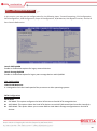
Network Security System
NSP-2C20
Always at the forefront of innovation
User Manual
1
Copyright
This publication contains information that is protected by copyright. No part of it may be reproduced in any
form or by any means or used to make any transformation adaptation without the prior written permission
from the copyright holders.
This publication is provided for informational purposes only. The manufacturer makes no representations or
warranties with respect to the contents or use of this manual and specifically disclaims any express or implied
warranties of merchantability or fitness for any particular purpose. The user will assume the entire risk of the
use or the results of the use of this document. Further, the manufacturer reserves the right to revise this
publication and make changes to its contents at any time, without obligation to notify any person or entity of
such revisions or changes.
© 2011. All Rights Reserved.
Trademarks
All trademarks and registered trademarks of products appearing in this manual are the properties of their
respective holders.
FCC and DOC Statement on Class A
This equipment has been tested and found to comply with the limits for a Class A digital device, pursuant to
Part 15 of the FCC rules. These limits are designed to provide reasonable protection against harmful
interference when the equipment is operated in a residential installation. This equipment generates, uses,
and can radiate radio frequency energy and, if not installed and used in accordance with the instruction
manual, may cause harmful interference to radio communications. However, there is no guarantee that
interference will not occur in a particular installation. If this equipment does cause harmful interference to
radio or television reception, which can be determined by turning the equipment off and on, the user is
encouraged to try to correct the interference by one or more of the following measures:
Reorient or relocate the receiving antenna.
Increase the separation between the equipment and the receiver.
Connect the equipment into an outlet on a circuit different from that to which the receiver is connected.
Consult the dealer or an experienced radio TV technician for help.
Notice:
1. The changes or modifications not expressly approved by the party responsible for compliance could void
the user’s authority to operate the equipment.
2. Shielded interface cables must be used in order to comply with the emission limits.
2
Warranty
1. Warranty does not cover damages or failures that are raised from misuse of the product, inability to use
the product, unauthorized replacement or alteration of components and product specifications.
2. The warranty is void if the product has been subject to physical abuse, improper installation, modification,
accidents or unauthorized repair of the product.
3. Unless otherwise instructed in this user’s manual, the user may not, under any circumstances, attempt to
perform service, adjustments or repairs on the product, whether in or out of warranty. It must be
returned to the purchase point, factory or authorized service agency for all such work.
4. We will not be liable for any indirect, special, incidental or consequential damages to the product that has
been modified or altered.
Static Electricity Precautions
It is quite easy to inadvertently damage your PC, system board, components or devices even before installing
them in your system unit. Static electrical discharge can damage computer components without causing any
signs of physical damage. You must take extra care in handling them to ensure against electrostatic build-up.
1. To prevent electrostatic build-up, leave the system board in its anti-static bag until you are ready to install
it.
2. Wear an antistatic wrist strap.
3. Do all preparation work on a static-free surface.
4. Hold the device only by its edges. Be careful not to touch any of the components, contacts or connections.
5. Avoid touching the pins or contacts on all modules and connectors. Hold modules or connectors by their
ends.
Important:
Electrostatic discharge (ESD) can damage your processor, disk drive and other
components. Perform the upgrade instruction procedures described at an ESD
workstation only. If such a station is not available, you can provide some ESD
protection by wearing an antistatic wrist strap and attaching it to a metal part of the
system chassis. If a wrist strap is unavailable, establish and maintain contact with the
system chassis throughout any procedures requiring ESD protection.
3
Safety Measures
To avoid damage to the system:
• Use the correct AC input voltage range.
To reduce the risk of electric shock:
• Unplug the power cord before removing the system chassis cover for installation or servicing. After
installation or servicing, cover the system chassis before plugging the power cord.
Battery:
• Danger of explosion if battery incorrectly replaced.
• Replace only with the same or equivalent type recommend by the manufacturer.
• Dispose of used batteries according to local ordinance.
Before Using the System
Before using the system, prepare basic system components.
If the system comes as a barebone; that is, none of the key components, including processor, memory, and
hard drive has been pre-installed as part of your purchase, you will need to at least ensure a compatible
counterpart is located and installed.
You will also need a few external system peripherals intended for the use of the system, a common pool with
at least a keyboard, a mouse, and a monitor is thus suggested.
4
Table of Content
Copyright .................................................................................................................................................................... 2
Trademarks .................................................................................................................................................................... 2
FCC and DOC Statement On Class A.............................................................................................................................. 2
Warranty ........................................................................................................................................................................ 3
Static Electricity Precautions ......................................................................................................................................... 3
Safety Measures ............................................................................................................................................................ 4
Before Using the System Board ..................................................................................................................................... 4
Table of Content ............................................................................................................................................................ 5
Chapter 1 General Information
1.1 Main Feature ........................................................................................................................................................... 7
1.2 Specifications ....................................................................................................................................................... 8
1.3 Optional LAN Module ....................................................................................................................................... 9
1.4 System Layout ................................................................................................................................................. 10
1.5 Indicators and Features .................................................................................................................................. 11
Chapter 2 Preparation
2.1 Before You Begin ...................................................................................................................................... 14
2.2 Precautions......................................................................................................................................................... 14
2.3 Open Up Top Cover............................................................................................................................................. 15
2.4 Accessing Processor & Memory .......................................................................................................................... 16
2.5 Adding 2.5”/3.5” SATA Hard Drive..................................................................................................................... 17
2.6 Accessing CompactFlash Card ........................................................................................................................ 18
Chapter 3 Operation
3.1 Turning On The System .................................................................................................................................... 20
3.2 Installing Operating System & Drivers ........................................................................................................ 22
3.3 Understanding LED Indicators ........................................................................................................................ 23
Chapter 4 BIOS Setup
4.1 Entering Setup ................................................................................................................................................ 26
4.2 Getting Help .................................................................................................................................................... 26
4.3 Control Keys .................................................................................................................................................... 26
4.4 The Main Menu ............................................................................................................................................... 27
4.5 The Advanced Menu........................................................................................................................................ 28
4.6 The Chipset Menu..................................................................................................................................................... 31
4.7 The Boot Menu................................................................................................................................................ 32
4.8 The Security Menu .......................................................................................................................................... 33
4.9 The Save & Exit Menu ..................................................................................................................................... 34
4.10 Event Logs ..................................................................................................................................................... 36
Chapter 5 Programming Guide
5.1 LAN Status Sample Code ................................................................................................................................ 38
5.2 LAN Switch Sample Code ................................................................................................................................ 43
5.3 WDT Sample Code .......................................................................................................................................... 52
Chapter 6 Q&A ................................................................................................................... 58
5
Chapter 1
General Information
6
1.1 Main Feature
Processor Performance
NSP-2C20 is a 2U Rack Mount Network Security System that, pre-installed with BNX-C206 security board,
featuring on Intel® C206 chipset, supports Intel® LGA1155 E3-1200 Xeon processor, and Gen-2/3 desktop
Celeron®, Pentium®, Core®-i3/i5/i7 processors that carry the built-in Intel® HD Graphic engine. Below is a
brief list of available processors as a quick reference:
Celeron® Processor: G540/G1620
Pentium® Processor: G850/G2120
Core®-i3 Processor: i3-2120/i3-3220
Core®-i5 Processor: i5-2400/i5-3550S
Core®-i7 Processor: i7-2600/i7-3770
E3-1200 Xeon Processor: E3-1225/E31275, E3-1225 V2/E3-1275 V2
8GB Memory for 64bit OS
The four Dual Channel DDR3 DIMM slots are designed to carry up to 32GB DDR3 1066/1333/1600MHz
SDRAM with Non-ECC support, ideally facilitating applications that demand total memory capacity for the
use of 64bit OS, beyond the 4GB barrier inherent in the 32bit OS.
Gigabit/10G LAN Ports on Expansion Module
NSP-2C20 comes with one default IO2 module that offers not only the basic system indication, USB port,
and console port, but also three RJ45 Gigabit LAN ports on Intel® 82574L and two SFP Gigabit LAN ports
on Intel® 82576EB. In additional to the five Gigabit LAN ports on IO2 module, two expansion slots are
designed for up to two extra LAN modules. Users are encouraged to explore the different deployments
using these LAN modules to achieve their demand of network port arrangement. Below is a list of all
available LAN modules:
4-Port RJ45 Gigabit LAN Module on Intel® 82580EB
4-Port SFP Gigabit LAN Module on Intel® 82580EB
2-Port SFP+ 10G LAN Module on Intel® 82599ES
List of Key Features
Intel® C206 Chipset
Intel® LGA1155 Xeon E3-1200 & E3-1200 V2 Processor
Intel® LGA1155 Gen-2/3 Desktop Celeron®, Pentium®, Core®-i3/i5/i7 Processor
Four DDR3 RAM Slots up to 32GB
Two internal 3.5” SATA Drive
One CompactFlash Socket
One SATADOM Port
One DB15 VGA at rear side
Two USB 2.0 Ports at front
One RJ45 Console Port at front
Default Three RJ45 and Two SFP Intel® Gigabit LAN Ports at front
Two Expansion Slots for each up to additional 4-Port Gigabit or 2-Port 10G LAN Ports
2U 1+1 300W Redundant Power Supply
2U Rack Mount of 430mm Depth
7
1.2 Specifications
Core Engine
Chipset
Intel® C206 PCH
Processor
Support Single Intel® E3-1200/1200 V2 Processor, Intel® Gen-2/3 Core i3, i5, i7 Processor
Memory
4x DDR3 1066/1333 DIMM Slots, up to 32GB
Display
CPU Integrated
Controller
Onboard 3x Intel® 82574L + 2x Intel® 82576EB GbE Controllers
LAN Module
Support 2x PCIe X8 Slots for LAN Module
SATA
2x internal 3.5” SATA3 Drive Bays or 4x 2.5” SATA Drive Bays
SATADOM
1x SATADOM Socket
CF
1x CompactFlash Socket
Indication
1x Power LED, 1x HDD LED, 1x Status LED
LAN
3x RJ45 1G Ports, 2x SFP 1G Ports
Console
1x RJ45 Type Console Port
USB
2x USB 2.0 Ports
Switch
1x Rock Type Power Switch
VGA
1x Optional DB15 VGA Port
Expansion
PCI
1x miniPCI Slot
Power
Type
2U 1+1 300W Redundant Power Supply, 100-240Vac, 47-63Hz
Cooling
CPU Fan
1x CPU Cooler Fan
System Fan
2x 80mm System Fans at rear side
H/W Monitoring
Monitor temperature, voltage, and fan speed, auto-throttling control at CPU overheat
Operating Temp.
0oC ~ 40oC
Storage Temp.
-20oC ~ 70oC
Humidity
10% ~ 90% (Non-Condensing)
Dimension
430mm (W) x 430mm (D) x 88mm (H)
Ethernet
Storage
Front I/O
Rear I/O
Other
Environment
Mechanical
8
1.3 Optional LAN Modules
BEM-C600-580-C4
BEM-C600-580-F4
BEM-C600-599-F2
Type
LAN Module
Chipset
Intel® 82580EB
Interface
PCIe X4
Network Port
Four RJ45 Gigabit
Bypass
1-Pair
Type
LAN Module
Chipset
Intel® 82580EB
Interface
PCIe X4
Network Port
Four SFP Fiber Gigabit
Type
LAN Module
Chipset
Intel® 82599ES
Interface
PCIe X8
Network Port
Two SFP+ 10G
9
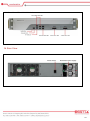
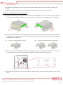
1.4 System Layout
Figure 1.1: System Layout of NSP-2C20
10
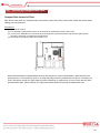
1.5 Indicators & Features
►Front View
With Two 4-Port RJ45 GbE LAN Modules
With Two 4-Port SFP GbE LAN Modules
11
With Two 2-Port SFP+ 10G LAN Modules
► Rear View
12
Chapter 2
Preparation
13
2.1 Before You Begin
A stable and clean working environment are essential. Dust and dirt can get into components and cause a
malfunction. Use containers to keep small components separated.
Adequate lighting and proper tools can prevent you from accidentally damaging the internal components. Most
of the procedures that follow require only a few simple tools, including the following:
A Philips screwdriver
A flat-tipped screwdriver
A set of jewelers Screwdrivers
A grounding strap
An anti-static pad
Using your fingers can disconnect most of the connections. It is recommended that you do not use
needle-nosed pliers to disconnect connections as these can damage the soft metal or plastic parts of the
connectors.
Before working on internal components, make sure that the power is off. Ground yourself before touching any
internal components, by touching a metal object. Static electricity can damage many of the electronic
components. Humid environment tend to have less static electricity than dry environments. A grounding strap is
warranted whenever danger of static electricity exists.
2.2 Precautions
Computer components and electronic circuit boards can be damaged by discharges of static electricity. Working
on the computers that are still connected to a power supply can be extremely dangerous. Follow the guidelines
below to avoid damage to your computer or yourself:
Always disconnect the unit from the power outlet whenever you are working inside the case.
If possible, wear a grounded wrist strap when you are working inside the computer case. Alternatively,
discharge any static electricity by touching the bare metal chassis of the unit case, or the bare metal body
of any other grounded appliance.
Hold electronic circuit boards by the edges only. Never touch the components on the board unless it is
necessary to do so. Do not flex or stress the circuit board.
Leave all components inside the static-proof packaging that they shipped with until they are ready for
installation.
Use correct screws and do not over tighten screws.
14
2.3 Open Up Top Cover
This is the first step of all to proceed with, if you are to install (or change) a processor (hard drive or memory
module).
Please remove the 6 screws on both sides indicated in the places below, prior to any moving of the top cover.
It is recommended to push the top cover backwards so as to detach the cover tongue out of the snatch-up at
front side, before the lift-up or removal of the top cover.
Securing the screws is essential for they would be re-used for the restoration of the top cover, after all
preparation procedures are completed.
15
2.4 Accessing Processor & Memory
Please refer to the Manual of BNX-C206 motherboard for substantial details as to adding processor, cooler,
and memory.
2.5 Adding 2.5”/3.5” SATA Hard Drive
Procedures to add up to two 3.5” Hard Drives:
(1) Turn off the system and open up the top cover.
(2) Acquire the HDD bracket from the top drive bay, attach this bracket onto your 3.5” Hard Drive as indicated
below so that the two furthest screw holes (from Hard Drive I/O) can be used to add screws. Please manage to
add another identical bracket on the other side of your 3.5” Hard Drive, symmetrically.
(3) Place the finished 3.5” Hard Drive subset onto the top drive bay, as indicated below (pick any drive bay from the
two), so that the Hard Drive I/O is facing CPU cooler (inwardly). Add four screws to secure this subset firmly.
16
(4) Add SATA signal cable along to the motherboard, and SATA power cable from power supply to finish up the
work.
(5) Please proceed to add the second 3.5” Hard Drive, if necessary, on the other available drive bay.
Procedures to add up to four 2.5” Hard Drives:
(1) Turn off the system and open up the top cover.
(2) As illustrated below, please have your first 2.5” Hard Drive assembled with the 2.5” Hard Drive holder. Add two
screws on one side, and another two screws on the other side, to firmly secure this Hard Drive with the holder.
(3) In case a second Hard Drive is to be added, you have choices to add this second Hard Drive at the bottom of the
first Hard Drive, or simply grab another set of Hard Drive holder and create another identical subset, ready to be
attached to the top drive bay.
Choice one: two drives within one holder
Choice two: two drives within separate holders
(4) Place the finished 2.5” Hard Drive subsets onto the top drive bay, as indicated below (if using two), so that the
Hard Drive I/O is facing CPU cooler (inwardly). Add eight screws to secure both subsets firmly.
(5) Add SATA signal cable along to the motherboard, and SATA power cable from power supply to finish up the
work.
17
2.6 Accessing CompactFlash Card
CompactFlash instead of CFast
NSP-2C20 comes with one CompactFlash card socket, rather than CFast card socket. Please be careful when
adding your flash devices.
Procedures:
(1) Turn off the system.
(2) The onboard CompactFlash socket can be located on motherboard (as the red circle).
(3) In case some difficulties are encountered at this approach, please detach the top drive bay plate before
inserting, removing, or swapping a CompactFlash.
(4) Restore the top drive bay plate if removed at (3).
Please be advised that CompactFlash card on IDE interface is never to be added or removed when the
system power is still turned on; that is, no plug-and-play scheme is enabled for this device. Disrespect of
such a limitation would very likely lead to system instability or malfunction, or even to the worst a fatal
system catastrophe. Please always turn off system power before accessing CompactFlash card.
18
Chapter 3
Operation
19
3.1 Turning On The System
Add your cables, such as USB keyboard, USB mouse, and DB15 VGA Cable as the merest devices to control the
system.
Access VGA Port
Please be noted that one DB15 VGA port is available internally on the motherboard and, however obscured by
the top cover, can be accessed by opening up the top cover. Please refer to the literature of BNX-C206
Security Board for details of the VGA location. However, if user is fully geared with convenient terminal access,
such a visual confirmation can be properly retrieved at console port.
Watch Input AC Power Range
Please leave the two AC power cords as the last cable to be added, right on the AC Inlet as indicated below
with blue circle. The AC input range of the built-in Power Supply is 100-240Vac. If your AC input is not within
this range, though rarely possible in fact, it is not compliant with the system and you should not plug in the AC
power cord.
System Is Up On AC Power
In some cases, depending on whether a BIOS setting has been configured to allow immediate power-on upon
the delivery of AC power, system might come right up unexpectedly for no particular reason. Please refer to
BIOS section for details with “Restore AC Power Loss”. Have you wish to bring it down, simply press once on
the power switch (located next to power supply with yellow circle), or press and hold for 4 seconds, to reach
that goal. However, in most occasions, without such abrupt event as stated above, simply press once on the
Power Switch to turn on the system.
Redundant Power Alarm
To start up, please make sure both power modules are firmly pushed into their positions. No alert signal
should be triggered with good and healthy power modules. In case one of the power modules is not in place,
out of order, or is not plugged with AC power cord, a loud alert signal (generated by power supply) will be
triggered. Under such a circumstance, please press once on the “alert disable button” (located next to the
power supply with red circle) to disable the annoying alert prior to any further debugging action. However, if
user decides not to press this button, and would prefer proceeding with the debugging actions, such as
pushing the module into position, swapping power module, or add AC power cord, the alert signal would be
automatically disabled upon these action.
20
Power LED
The power LED can be found at front panel and shall come lit constant ON at system start.
HDD LED
The HDD LED can also be found at front panel and shall blink in the wake of storage activity, such as SATA drive
or CompactFlash.
First screen & Optimal BIOS Setting
Once the system successfully boots up, it shall activate display signal on monitor, disclosing some system
information as checkpoints for debugging, thereafter users are encouraged to bring up BIOS setup menu to at
least load the optimal BIOS setting, as the first thing to do at power on. Please refer to the BIOS section for
substantial details.
21
3.2 Installing Operating System & Drivers
Confirm the Hard Drive List
The system is designed to allow booting from a variety of internal devices, including USB pen drive, SATA drive,
and CompactFlash drive, etc. Given the tiny footprint and slow performance of USB pen drive, SATA drive and
CompactFlash are more likely the devices to carry operating system and can be found in the detected drive list,
in the section of SATA Configuration.
In the event that a particular SATA device is not detected and prompted in the device list, hardly would the
system boot from it. Please turn off the system, check or re-apply the SATA cable and SATA power cable, or
re-insert CompactFlash card to ensure an appropriate connection.
Always Mind the SATA Mode
SATA controller is embedded in the Intel® C206 chipset, and shall run only in one single SATA mode at a time.
Three different modes are available: IDE, AHCI, and RAID. Please ensure that a SATA mode has been selected
for the installation, and always use this particular mode to boot the operating system installed on that SATA
mode. Failed to boot the operating system with the correct SATA mode would very probably run into system
collapse. While thus disaster occurs, please re-select a SATA mode to try again the advisability of such change,
so as to recollect the mode being used at the installation phase.
Procedures to load operating system:
(1)
(2)
(3)
(4)
(5)
(6)
(7)
(8)
(9)
Please attach USB CD-ROM or DVD-ROM drive.
Start or restart the system.
Press “del” to go to BIOS setup menu.
Choose to confirm SATA Controller status. If it is enabled, select a SATA mode and go to (6).
If SATA Controller is disabled, bring it up and reboot to allow a re-detection of Hard Drives.
Confirm if the Hard Drive has been detected by the prompt of it on the drive list.
Scroll and choose to boot from optical device (CD-ROM or DVD-ROM).
Save and reboot the system to activate the change and start the installation.
Upon reception of messages or instruction from Operating System CD or DVD, please proceed with the rest of
the work as installer instructs.
Loading Extra Driver Files
Some challenges might occur during the installation, such as “no Hard Drive detected”, where extra driver files
are needed. This is mostly found, when AHCI or RAID mode are selected, in operating systems such as
Windows-XP, where a USB floppy drive loaded with SATA driver should be prepared and attached on USB port
and, at the prompt of such a message, please press “F6” key while being asked to do so, to allow the installer
integrate the driver file from floppy drive. Windows-7 or above apparently do not seem to come with such an
issue against the onboard Intel® C206 SATA Controller, and hence no extra driver should be needed.
On completion of the installation of operating system such as Microsoft Windows, please find the driver CD in
the enclosed accessory bag and proceed with driver files installation in the sequence as: INF (Chipset), VGA,
and LAN. If some driver updates are available by Windows Update, please accept the updates when prompted.
22
3.3 Understanding LAN Indicators
Activity LED
The left LED is LAN Port Activity LED, with three different indication status:
(1) Constant Yellow: Network is connected.
(2) Blinking Yellow: Network activity is on-going.
(3) Off: Network is not connected.
LAN Speed LED
The right LED is LAN Port Speed LED, with three different speeds:
(1) Amber: 1000 Speed
(2) Green: 100 Speed
(3) Off: 10 Speed.
Summary Table
LED
RJ45 NIC Linkage
(Left Side)
RJ45 NIC Mode
(Right Side)
Color
Yellow
Yellow
Off
Amber
Green
Off
State
On
Blinking
Off
On
On
Off
Description
LAN linked
LAN accessing
No LAN linked
Gigabit mode
100M mode
10M mode
23
Chapter 4
BIOS Setup
24
About the BIOS
The BIOS (Basic Input and Output System) Setup program is a menu driven utility that enables you to make changes to
the system configuration and tailor your system to suit your individual work needs. It is a ROM-based configuration
utility that displays the system’s configuration status and provides you with a tool to set system parameters. These
parameters are stored in non-volatile battery-backed-up CMOS RAM that saves this information even when the
power is turned off. When the system is turned back on, the system is configured with the values stored in CMOS.
With easy-to-use pull down menus, you can configure such items as:
Hard drives, diskette drives, and peripherals
Video display type and display options
Password protection from unauthorized use
Power management features
When to Run BIOS
This program should be executed under the following conditions:
When changing the system configurations.
When a configuration error is detected by the system and you are prompted to make changes to the Setup
program.
When resetting the system clock.
When setting the CPU clock speed so that it automatically runs either fast or slow.
When redefining the communication ports to prevent any conflicts.
When making changes to the Power Management configuration.
When changing the password or making other changes to the security setup.
Normally, CMOS setup is needed when the system hardware is not consistent with the information contained in the
CMOS RAM, whenever the CMOS RAM loses power, or when the system features need to be changed.
When to Update BIOS
In the event that new features are released and a BIOS update is required, you will need to update your BIOS on
your own, with the help of an appropriate guide, a reference tool, and some command files for the job.
Please seek for help from your local dealer, or send your request to our technical support department.
25
4.1 Entering Setup
When the system is powered on, the BIOS will initiate the Power-On-Self-Test (POST) routines. These routines
perform various diagnostic checks. If an error is encountered, the error will be reported in one of two different ways:
If the error occurs before the display device is initialized, a series of beeps will be transmitted.
If the error occurs after the display device is initialized, the screen will display the error message.
Powering on the computer and immediately pressing <Del> allows you to enter Setup. Another way to enter Setup is
to power on the computer and wait for the following message during the POST:
TO ENTER SETUP BEFORE BOOT
PRESS <CTRL-ALT-ESC> OR <DEL> KEY
Press the <Del> key or press the <Ctrl>, <Alt>, and <Esc> keys to enter Setup.
4.2 Getting Help
The online description of the highlighted setup item is displayed at the right pane of the menu at all time.
Press F1 to pop up a small help window that lists all the function keys and its use.
To exit the Help Window, press <F1> or <Esc>.
4.3 Control Keys
The table below lists all the function keys for the navigation in the BIOS setup menu.
Function Key
Description
Up/Down Arrow Key
Move Up/Down
Left/Right Arrow Key
Move Left/Right
Enter Key
Select
+/- Key
Change value
ESC
Exit
Tab
Select a Field
F1
General Help
F4
Save & Exit
To exit the Help Window, press <F1> or <Esc>.
26
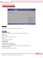
4.4 The Main Menu
Figure 4-1: BIOS Setup Utility Main Menu
The menu bar on the top of the first screen has the following submenus:
Main: Basic system configuration.
Advanced: Advanced system settings.
Chipset: Other functions.
Boot: System boot configuration.
Security: Configure Supervisor and User Password
Save & Exit: Exit options as well as loading optimal defaults
Event & Logs: Store system events, such as chassis intrusion and power loss, etc.
System Time [xx:xx:xx]: Set the system time.
System Date [Day xx/xx/xxxx]: Set the system date.
27
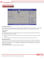
4.5 The Advanced Menu
In this section, you may set the configurations for the following items: Trusted Computing, CPU Configuration,
SATA Configuration, USB Configuration, Super IO Configuration, H/W Monitor, LAN Bypass Function, and Serial
Port Console Redirection.
Launch PXE OpROM
Enable or disable boot options for legacy network devices.
Launch Storage OpROM
Enable or disable boot option for legacy mass storage devices with OpROM
CPU Configuration
Limit CPUID Maximum
It is designed to limit the listed speed of the processor to older operating systems.
SATA Configuration
SATA Mode
IDE Mode: This option configures the Serial ATA drives as Parallel ATA storage devices.
AHCI Mode: This option allows the Serial ATA devices to use AHCI (Advanced Host Controller Interface).
RAID Mode: This option allows you to create RAID or Intel Matrix Storage configuration on Serial ATA
devices.
28
Serial ATA Controller 0-1
This option allows you to Enable/Disabled Serial ATA Controller 0-1.
If AHCI or RAID mode is selected, all detected SATA Hard Drives will be prompted on the list.
USB Configuration
Legacy USB Support
Enabled: Enables legacy USB.
Auto: Disables support for legacy when no USB devices are connected.
Disabled: Keep USB devices available only for EFI applications.
EHCI Hand-off
This is a workaround for OSes that does not support EHCI hand-off. The EHCI ownership change should be
claimed by the EHCI driver.
Port 60/64 Emulation
Enables I/O port 60h/64h emulation support. This should be enabled for the complete USB keyboard legacy
support for non-USB aware OSes.
Super IO Configuration
Restore AC Power Loss
Off: When power returns after an AC power failure, the system’s power is off. You must press the Power
button to power-on the system.
On: When power returns after an AC power failure, the system will automatically power-on.
Last State: When power returns after an AC power failure, the system will return to the state where you
left off before power failure occurs. If the system’s power is off when AC power failure occurs, it will
remain off when power returns. If the system’s power is on when AC power failure occurs, the system
will power-on when power returns.
WatchDog Timer
This is used to select the time interval of the Watchdog timer. If the system hangs or fails to function, it will
reset at the set time interval so that your system will continue to operate.
Serial Port 0/1 Configuration
Serial Port
Enables or disables the serial port.
Change Settings
Selects the IO/IRQ setting of the I/O device.
29
Parallel Port Configuration
Parallel Port
Enables or disables the Parallel port.
Change Settings
Selects the IO/IRQ setting of the I/O device.
Device Mode
Change the printer port mode.
LAN Bypass Function
LAN Group1 Power ON and LAN Group2 Power ON
The options are Pass Through and Bypass.
LAN Group1 Power OFF and LAN Group2 Power OFF
The options are Pass Through and Bypass.
WDT
This is used to enable or disable the Watchdog Timer function.
Serial Port Console Redirection
Console Redirection
Enables or disables Console Redirection function of each Serial Port.
30
4.6 The Chipset Menu
North Bridge
IGD Memory
Selects the internal graphics device’s shared memory size.
South Bridge
Wake on LAN from S5
When enabled, it allows the system to wake from S5 via the network port.
After G3
Power Off / WOL
Power-on the system via WOL after G3.
Power On
Power-on the system after G3.
USB Configuration
All USB Devices
Enables or disables all USB devices.
EHCI Controller 1 and EHCI Controller 2
These are used to enable or disable Enhanced Host Controller Interface (USB 2.0).
USB Port 0 to USB Port 5
Enables or disables the selected USB port.
31
4.7 The Boot Menu
Bootup NumLock State
This setting is to set the Num Lock status when the system is powered on. Setting to [On] will turn on the Num
Lock key when the system is powered on. Setting to [Off] will allow users to use the arrow keys on the
numeric keypad.
Quiet Boot
This BIOS feature determines if the BIOS should hide the normal POST messages with the motherboard or
system manufacturer’s full-screen logo.
When it is enabled, the BIOS will display the full-screen logo during the boot-up sequence, hiding normal POST
messages.
When it is disabled, the BIOS will display the normal POST messages, instead of the full-screen logo.
Boot Option Priorities
The items allow you to set the sequence of boot devices where BIOS attempts to load the disk operating
system. First press <Enter> to enter the sub-menu. Then you may use the arrow keys ( ↑↓ ) to select the
desired device, then press <+>, <-> or <PageUp>, <PageDown> key to move it up/down in the priority list.
Hard Drive BBS Priorities
This setting allows users to set the Hard Drive boot sequence.
32
4.8 The Security Menu
Administrator Password
Administrator Password controls access to the BIOS Setup utility. Users will be prompted for Administrator
password only when they enter BIOS Setup.
User Password
User Password controls access to the system at boot and access to the BIOS Setup utility. Users will be
prompted for User password when they power on the system or enter BIOS Setup. In BIOS Setup, users will
have Administrator rights.
33
4.9 The Save & Exit Menu
Discard Changes and Exit
To exit the Setup utility without saving the changes, select this field then press <Enter>. You may be prompted
to confirm again before exiting.
You can also press <ESC> to exit without saving the changes.
Save Changes and Reset
To save the changes, select this field and then press <Enter>. A dialog box will appear. Select Yes to reset the
system after saving all changes made.
Discard Changes and Reset
To discard the changes, select this field and then press <Enter>. A dialog box will appear. Select Yes to reset
the system setup without saving any changes.
Save Changes
Save changes done so far to any of the setup options.
Dischard Changes
To discard the changes, select this field then press <Enter>. A dialog box will appear. Confirm by selecting Yes
to discard all changes made and restore the previously saved settings.
You can also press <F7> to discard the changes.
Restore Defaults
To restore and load the optimized default values, select this field and then press <Enter>. A dialog box will
appear. Select Yes to restore the default values of all the setup options.
34
Save as User Defaults
To save changes done so far as user default, select this field and then press <Enter>. A dialog box will appear.
Select Yes to save values as user default.
Restore User Defaults
To restore user default to all the setup options, select this field and then press <Enter>. A dialog box will
appear. Select Yes to restore user default.
35
4.10 Event Logs
View Smbios Event Log
To view Smbios event log.
View System Event Log
To view system event log.
Change Smbios Event Log Settings
Erase Event Log
Choose options for erasing Smbios event log. Erasing is done prior to any logging activation during reset.
When Log is Full
Choose options for reactions to a full Smbios event log.
MECI
Multi Event Count Increment: The number of occurrences of a duplicate event that must pass before the
multiple-event counter associated with the log entry is updated, specified as a numeric value in the range of 1
to 255.
METW
Multi Event Time Window: The number of minutes which must pass between duplicate log entries which
utilize a multiple-event counter. The value ranges from 0 to 99.
Log OEM Codes
Enable or disable the logging of EFI Status codes as OEM codes (if not already converted to legacy)
Convert OEM Codes
Enable or disable the converting of EFI Status Codes to Standard Smbios Types (Not all may be translated).
36
Chapter 5
Programming Guide
37
5.1 LAN Status Sample Code
#include <stdio.h>
//-----------------------------------------------------------------------//CMOS Port Address
#define CMOS_INDX_PORT
#define CMOS_DATA_PORT
//LAN Status Flag Address
#define LAN_STATUS_FLAG1
#define LAN_STATUS_FLAG2
0x70
0x71
Ox55
Ox56
//LAN Status Flag Definition
#define LAN1_PWRON_FLAG
0x00
#define LAN1_PWROFF_FLAG
0x01
#define LAN2_PWRON_FLAG
0x02
#define LAN2_PWROFF_FLAG
0x03
#define LAN_WDT_FLAG
0x04
#define LAN3_PWRON_FLAG
0x05
#define LAN3_PWROFF_FLAG
0x06
#define LAN4_PWRON_FLAG
0x00
#define LAN4_PWROFF_FLAG
0x01
//-----------------------------------------------------------------------void GpioInit(void);
void GpioOut(char, char);
void SetBit(char*, char);
void ClrBit(char*, char);
char GetBit(char Data, char Bit);
//-----------------------------------------------------------------------main(void)
{
char data1, data2;
char *BP = “ByPass”;
char *PT = “PassThrough”;
char *RST = “Reset”;
38
char LAN1PowerON[15], LAN1PowerOFF[15], LAN2PowerON[15], LAN2PowerOFF[15];
char LAN3PowerON[15], LAN3PowerOFF[15], LAN4PowerON[15], LAN4PowerOFF[15];
char WDT[15];
outportb(CMOS_INDX_PORT, LAN_STATUS_FLAG1);
data1 = inportb(CMOS_DATA_PORT);
outportb(CMOS_INDX_PORT, LAN_STATUS_FLAG2);
data2 = inportb(CMOS_DATA_PORT);
if(GetBit(data1, LAN1_PWRON_FLAG))
strcpy(Lan1PowerON, BP);
else
strcpy(Lan1PowerON, PT);
if(GetBit(data1, LAN1_PWROFF_FLAG))
strcpy(Lan1PowerOFF, BP);
else
strcpy(Lan1PowerOFF, PT);
if(GetBit(data1, LAN2_PWRON_FLAG))
strcpy(Lan2PowerON, BP);
else
strcpy(Lan2PowerON, PT);
if(GetBit(data1, LAN2_PWROFF_FLAG))
strcpy(Lan2PowerOFF, BP);
else
strcpy(Lan2PowerOFF, PT);
if(GetBit(data1, LAN_WDT_FLAG))
strcpy(WDT, BP);
else
strcpy(WDT, Rst);
if(GetBit(data1, LAN3_PWRON_FLAG))
strcpy(Lan3PowerON, BP);
else
if(GetBit(data1, LAN3_PWROFF_FLAG))
else
if(GetBit(data2, LAN4_PWRON_FLAG))
else
if(GetBit(data2, LAN4_PWROFF_FLAG))
else
strcpy(Lan3PowerON, PT);
strcpy(Lan3PowerOFF, BP);
strcpy(Lan3PowerOFF, PT);
strcpy(Lan4PowerON, BP);
strcpy(Lan4PowerON, PT);
strcpy(Lan4PowerOFF, BP);
strcpy(Lan4PowerOFF, PT);
printf(“[LAN 1]\n”)
printf(“POWER ON:%s\n”, LAN1PowerON);
printf(“POWER OFF:%s\n”, LAN1PowerOFF);
printf(“[LAN 2]\n”)
printf(“POWER ON:%s\n”, LAN2PowerON);
printf(“POWER OFF:%s\n”, LAN2PowerOFF);
printf(“[LAN 3]\n”)
printf(“POWER ON:%s\n”, LAN3PowerON);
printf(“POWER OFF:%s\n”, LAN3PowerOFF);
printf(“[LAN 4]\n”)
printf(“POWER ON:%s\n”, LAN4PowerON);
39
printf(“POWER OFF:%s\n”, LAN4PowerOFF);
printf(“[WDT]\n”)
printf(“WDT Event:%s\n”, WDT);
return;
}
//-----------------------------------------------------------------------void SetBit(char *Data, char Bit)
{
switch(Bit)
{
switch(Bit)
{
case 0:
*Data |= 0x01;
break;
case 1:
*Data |= 0x02;
break;
case 2:
*Data |= 0x04;
break;
case 3:
*Data |= 0x08;
break;
case 4:
*Data |= 0x10;
break;
case 5:
*Data |= 0x20;
break;
case 6:
*Data |= 0x40;
break;
case 7:
*Data |= 0x80;
break;
}
}
40
void ClrBit(char *Data, char Bit)
{
switch(Bit)
{
case 0:
*Data &= 0xFE;
break;
case 1:
*Data &= 0xFD;
break;
case 2:
*Data &= 0xFB;
break;
case 3:
*Data &= 0xF7;
break;
case 4:
*Data &= 0xEF;
break;
case 5:
*Data &= 0xDF;
break;
case 6:
*Data &= 0xBF;
break;
case 7:
*Data &= 0x7F;
break;
}
}
//-----------------------------------------------------------------------char GetBit(char Data, char Bit)
{
switch(Bit)
{
41
case 0:
*Data &= 0x01;
break;
case 1:
*Data &= 0x02;
break;
case 2:
*Data &= 0x04;
break;
case 3:
*Data &= 0x08;
break;
case 4:
*Data &= 0x10;
break;
case 5:
*Data &= 0x20;
break;
case 6:
*Data &= 0x40;
break;
case 7:
*Data &= 0x80;
break;
}
if (data == 0)
else
return 0;
return 1;
}
//------------------------------------------------------------------------
42
5.2 LAN Switch Sample Code
#include <stdio.h>
//-----------------------------------------------------------------------//LPC Port Address
#define ADDR_PORT
#define DATA_PORT
0x2E
0x2F
//GPIO Pin Definition
#define LAN_LOCK
#define LAN_COMMAND
#define LAN_PWRON
#define LAN_PWROFF
#define LAN_WDT
0x04
0x07
0x01
0x05
0x06
//CMOS Port Address
#define CMOS_INDX_PORT
0x70
#define CMOS_DATA_PORT
0x71
//LAN Status Flag Address
#define LAN_STATUS_FLAG1 0x55
#define LAN_STATUS_FLAG2 0x56
//LAN Status Flag Definition
#define LAN1_PWRON_FLAG
0x00
#define LAN1_PWROFF_FLAG 0x01
#define LAN2_PWRON_FLAG
0x02
#define LAN2_PWROFF_FLAG 0x03
#define LAN_WDT_FLAG
0x04
#define LAN3_PWRON_FLAG
0x055
#define LAN3_PWROFF_FLAG 0x06
#define LAN4_PWRON_FLAG
0x00
#define LAN4_PWROFF_FLAG 0x01
//-----------------------------------------------------------------------void GpioInit(void);
void GpioOut(char, char);
43
void SetBit(char*, char);
void ClrBit(char*, char);
void SetStatusFlag(char, char, char, char);
//-----------------------------------------------------------------------main(int argc, char *argv[])
{
int PairSel, PowerOn, PowerOff, WDT;
if(argc == 5)
{
PairSel
= strtol(argv[1], NULL,
PowerOn
= strtol(argv[2], NULL,
PowerOff = strtol(argv[3], NULL,
WDT
= strtol(argv[4], NULL,
}
else
{
printf(“Command Error!!\n”);
return;
}
16);
16);
16);
16);
//Init GPIO
GpioInit();
GpioOut(LAN_LOCK, 0);
GpioOut(LAN_COMMAND, 0);
//Command Start: Set LAN_LOCK pin to high level
GpioOut(LAN_LOCK, 1);
delay(1);
//ByPass/PassThough Setting
//Set High/Low level to corresponding pins
// High => Bypass
// Low => PassThrough
GpioOut(LAN_PWRON, PowerOn);
GpioOut(LAN_PWROFF, PowerOff);
GpioOut(LAN_WDT, WDT);
//LAN Pair Selection
//Generate N pulses to select the Nth LAN pair
44
switch(PairSel)
{
case 1: GpioOut(LAN_COMMAND, 1);//
delay(1);//
break;
case 2:
case 3:
__|1ms|__
GpioOut(LAN_COMMAND, 1);
delay(1);
GpioOut(LAN_COMMAND, 0);
delay(1);
GpioOut(LAN_COMMAND, 1);//
delay(1);//
break;
____
___
__|1ms|__|1ms|__
GpioOut(LAN_COMMAND, 1);
delay(1);
GpioOut(LAN_COMMAND, 0);
delay(1);
GpioOut(LAN_COMMAND, 1);
delay(1);
GpioOut(LAN_COMMAND, 0);
delay(1);
GpioOut(LAN_COMMAND, 1);//
delay(1);//
break;
case 4:
____
GpioOut(LAN_COMMAND,
delay(1);
GpioOut(LAN_COMMAND,
delay(1);
GpioOut(LAN_COMMAND,
delay(1);
GpioOut(LAN_COMMAND,
delay(1);
____
___
____
__|1ms|__|1ms|__|1ms|__
1);
0);
1);
0);
GpioOut(LAN_COMMAND, 1);
delay(1);
GpioOut(LAN_COMMAND, 0);
delay(1);
45
GpioOut(LAN_COMMAND, 1);//
delay(1);//
break;
____
___
____
____
__|1ms|__|1ms|__|1ms|__|1ms|__
}
//Command End: Set LAN_COMMAND and LAN_LOCK to low level
GpioOut(LAN_COMMAND, 0);
GpioOut(LAN_LOCK, 0);
//Save LAN Status to CMOS
SetStatusFlag(PairSel, PowerOn, PowerOff, WDT);
Return;
}
//-----------------------------------------------------------------------void GpioInit(void)
{
char data;
outportb(ADDR_PORT, 0x87);
outportb(ADDR_PORT, 0x87);
//Select logical device 9
outportb(ADDR_PORT, 0x07);
outportb(DATA_PORT, 0x09);
//Enable GPIO_3 (Set bit 1=1)
outportb(ADDR_PORT, 0x30);
data = inportb(DATA_Port);
data = data | 0x02;
outportb(DATA_PORT, DATA);
//Disable SDA input, Disable SCL input (GP32.33.34) (Set bit1=0, bit2=1, bit3=1)
outportb(ADDR_PORT, 0x2A);
data = inportb(DATA_Port);
data = data & 0xFD;
data = data | 0x0C;
outportb(DATA_PORT, DATA);
46
//Enable GPIO_3 (GP32.33.34) (Set bit5.6.7=0)
outportb(ADDR_PORT, 0x2C);
data = inportb(DATA_Port);
data = data & 0x1F;
outportb(DATA_PORT, DATA);
//Initial GP0, GP1, GP4, GP5, GP6, GP7 pin status
outportb(ADDR_PORT, 0xF1);
data = inportb(DATA_Port);
data = data & 0x0C;
outportb(DATA_PORT, DATA);
//Set GP0, GP1, GP4, GP5, GP6, GP7 as output mode
outportb(ADDR_PORT, 0xF0);
data = inportb(DATA_Port);
data = data & 0x0C;
outportb(DATA_PORT, DATA);
outportb(ADDR_PORT, 0xAA);
}
//-----------------------------------------------------------------------void GpioOut(char bit, char level)
{
Char data;
outportb(ADDR_PORT, 0x87);
outportb(ADDR_PORT, 0x87);
outportb(ADDR_PORT, 0xF1);
data = inportb(DATA_PORT);
if(Level == 1){
SetBit(&data,Bit);
}
else {
ClrBit(&data,Bit);
}
outportb(DATA_PORT, DATA);
47
outportb(ADDR_PORT, 0xAA);
}
//-----------------------------------------------------------------------void SetStatusFlag(char LANPair, char PowerON, char PowerOFF, char WDT)
{
char data;
switch(LANPair)
{
case 1:
outportb(CMOS_INDX_PORT, LAN_STATUS_FLAG1);
data = inportb(CMOS_DATA_PORT);
if(PowerON) SetBit(&data, LAN1_PWRON_FLAG);
else ClrBit (&data, LAN1_PWRON_FLAG);
if(PowerOFF) SetBit(&data, LAN1_PWROFF_FLAG);
else ClrBit (&data, LAN1_PWROFF_FLAG);
if(WDT) SetBit(&data, LAN_WDT_FLAG);
else ClrBit (&data, LAN_WDT_FLAG);
outportb(CMOS_INDX_PORT, LAN_STATUS_FLAG1);
outportb(CMOS_DATA_PORT, data);
break;
case 2:
outportb(CMOS_INDX_PORT, LAN_STATUS_FLAG1);
data = inportb(CMOS_DATA_PORT);
if(PowerON) SetBit(&data, LAN2_PWRON_FLAG);
else ClrBit (&data, LAN2_PWRON_FLAG);
if(PowerOFF) SetBit(&data, LAN2_PWROFF_FLAG);
else ClrBit (&data, LAN2_PWROFF_FLAG);
if(WDT) SetBit(&data, LAN_WDT_FLAG);
else ClrBit (&data, LAN_WDT_FLAG);
outportb(CMOS_INDX_PORT, LAN_STATUS_FLAG1);
outportb(CMOS_DATA_PORT, data);
break;
case 3:
outportb(CMOS_INDX_PORT, LAN_STATUS_FLAG1);
data = inportb(CMOS_DATA_PORT);
if(PowerON) SetBit(&data, LAN3_PWRON_FLAG);
else
ClrBit (&data, LAN3_PWRON_FLAG);
if(PowerOFF) SetBit(&data, LAN3_PWROFF_FLAG);
48
else
ClrBit (&data, LAN3_PWROFF_FLAG);
if(WDT) SetBit(&data, LAN_WDT_FLAG);
else ClrBit (&data, LAN_WDT_FLAG);
outportb(CMOS_INDX_PORT, LAN_STATUS_FLAG1);
outportb(CMOS_DATA_PORT, data);
break;
case 4:
outportb(CMOS_INDX_PORT, LAN_STATUS_FLAG2);
data = inportb(CMOS_DATA_PORT);
if(PowerON) SetBit(&data, LAN4_PWRON_FLAG);
else ClrBit (&data, LAN4_PWRON_FLAG);
if(PowerOFF) SetBit(&data, LAN4_PWROFF_FLAG);
else ClrBit (&data, LAN4_PWROFF_FLAG);
if(WDT) SetBit(&data, LAN_WDT_FLAG);
else ClrBit (&data, LAN_WDT_FLAG);
outportb(CMOS_INDX_PORT, LAN_STATUS_FLAG2);
outportb(CMOS_DATA_PORT, data);
break;
}
}
//-----------------------------------------------------------------------void SetBit (char *Data, char Bit)
{
switch(Bit);
{
case 0:
*Data |= 0x01;
break;
case 1:
*Data |= 0x02;
break;
case 2:
*Data |= 0x04;
break;
case 3:
*Data |= 0x08;
break;
case 4:
*Data |= 0x10;
49
break;
case 5:
*Data |= 0x20;
break;
case 6:
*Data |= 0x40;
break;
case 7:
*Data |= 0x80;
break;
}
}
//-----------------------------------------------------------------------void ClrBit (char *Data, char Bit)
{
switch(Bit);
{
case 0:
*Data &= 0xFE;
break;
case 1:
*Data &= 0xFD;
break;
case 2:
*Data &= 0xFB;
break;
case 3:
*Data &= 0xF7;
break;
case 4:
*Data &= 0xEF;
break;
case 5:
*Data &= 0xDF;
break;
case 6:
*Data &= 0xBF;
break;
case 7:
50
*Data &= 0x7F;
break;
}
}
51
5.3 WDT Sample Code
//-----------------------------------------------------------------------#include <stdio.h>
//-----------------------------------------------------------------------#define ADDR_PORT 0x2E
#define DATA_PORT 0x2F
//-----------------------------------------------------------------------void WdtInit(void);
void SetWdtTime(char);
char GetWdtTime(void);
void SetBit(char*, char);
void ClrBit(char*, char);
//-----------------------------------------------------------------------main(int argc, char *argv[])
{
int PairSel, PowerOn, PowerOff, WDT;
char count, data;
if(argc==2)
{
count = strtol(argv[1], NULL, 10);
}
else
{
printf(“Command Error!!\n”);
return;
}
WdtInit();
SetWdtTime(count);
while(1)
{
Data = GetWdtTime();
52
delay(100);
printf(“\r Time Remaining: %d”, data);
if(data==1) break;
}
delay(1000);
printf(“\r Time Remaing: 0”);
printf(“\n Time Up!!\n”);
WdtInit();
SetWdtTime(0);
return;
}
//-----------------------------------------------------------------------void WdtInit(void)
{
char data;
outportb(ADDR_PORT, 0x87);
outportb(ADDR_PORT, 0x87);
//Set WDT Pin77 as WDTO#
outportb(ADDR_PORT, 0x2D);
data = inportb(DATA_PORT);
ClrBit(&data, 0);
outportb(DATA_PORT, data);
//Select LDN 8
outportb(ADDR_PORT, 0x07);
outportb(DATA_PORT, 0x08);
//Clear WDTO# Status bit
outportb(ADDR_PORT, 0xF7);
data = inportb(DATA_PORT);
ClrBit(&data, 4);
outportb(DATA_PORT, data);
//Enable Watch Dog Timer
outportb(ADDR_PORT, 0x30);
data = inportb(DATA_PORT);
53
SetBit(&data, 0);
outportb(DATA_PORT, data);
//Select Second Mode
outportb(ADDR_PORT, 0xF5);
data = inportb(DATA_PORT);
ClrBit(&data, 3);
outportb(DATA_PORT, data);
outportb(ADDR_PORT, 0xAA);
}
//-----------------------------------------------------------------------void SetWdtTime(char count)
{
outportb(ADDR_PORT, 0x87);
outportb(ADDR_PORT, 0x87);
//Select LDN 8
outportb(ADDR_PORT, 0x07);
outportb(DATA_PORT, 0x08);
//Set Count
outportb(ADDR_PORT, 0xF6);
outportb(DATA_PORT, count);
outportb(ADDR_PORT, 0xAA);
}
//-----------------------------------------------------------------------char GetWdtTime(void)
{
char data;
outportb(ADDR_PORT, 0x87);
outportb(ADDR_PORT, 0x87);
//Select LDN 8
outportb(ADDR_PORT, 0x07);
outportb(DATA_PORT, 0x08);
54
//Get Remaining Count
outportb(ADDR_PORT, 0xF6);
data = inportb(DATA_PORT);
outportb(ADDR_PORT, 0xAA);
return data;
}
//-----------------------------------------------------------------------void SetBit(char *Data, char Bit)
{
switch(Bit)
{
case 0:
*Data |= 0x01;
break;
case 1:
*Data |= 0x02;
break;
case 2:
*Data |= 0x04;
break;
case 3:
*Data |= 0x08;
break;
case 4:
*Data |= 0x10;
break;
case 5:
*Data |= 0x20;
break;
case 6:
*Data |= 0x40;
break;
case 7:
*Data |= 0x80;
break;
}
}
55
//-----------------------------------------------------------------------void ClrBit(char *Data, char Bit)
{
switch(Bit)
{
case 0:
*Data |= 0xFE;
break;
case 1:
*Data |= 0xFD;
break;
case 2:
*Data |= 0xFB;
break;
case 3:
*Data |= 0xF7;
break;
case 4:
*Data |= 0xEF;
break;
case 5:
*Data |= 0xDF;
break;
case 6:
*Data |= 0xBF;
break;
case 7:
*Data |= 0x7F;
break;
}
}
//------------------------------------------------------------------------
56
Chapter 6
Q&A
57
Q: The power switch is pressed, but nothing happens.
A: Please check the following before you call out for help:
(1) Loose AC Power Cord => Push again.
(2) Loose power cable (both 24-pin and 4-pin) => Push again.
(3) A bad or loose power switch => Reseat the power switch on the header again.
Q: I can turn on the power, but the motherboard does not boot.
A: Please check the following before you call out for help:
(1)
(2)
(3)
(4)
(5)
(6)
Unevenly populated memory modules on the slots => Re-populate the memory module again.
Unevenly seated CPU on the socket => Reseat the CPU again.
CMOS checksum error => Clear CMOS or reseat the CMOS battery again.
Bad Hard Drive => Remove SATA signal cable or CompactFlash card and boot again.
Bad PCI card or riser card => Remove PCI card and/or PCI riser card and boot again.
Bad external devices => Detach RS-232 cable, LAN cable, and USB cable, and boot again.
Q: BIOS POST prompts but gets stuck.
A: Please check the following before you call out for help:
(1) CMOS checksum error due to Clear CMOS approach => Press F1 to bring up BIOS setup menu and load optimal
setting.
(2) Bad Hard Drive => Remove SATA signal cable or CompactFlash card and boot again.
(3) Bad external devices => Detach RS-232 cable, LAN cable, and USB cable, and boot again.
Q: Power LED on power switch is not lit on
A: Please reseat the power switch and try again.
Q: HDD LED does not blink
A: Please reseat the HDD LED and try again.
Q: USB Keyboard does not work at DOS mode.
A: Please check the following before you call out for help:
(1) Check if USB keyboard is well plugged on USB port.
(2) Go to BIOS setup menu, Advanced/USB Configuration, and make sure Legacy USB Support is enabled.
58
Q: System does not boot from USB CD-ROM/DVD-ROM
A: Please check the following before you call out for help:
(1)
(2)
(3)
(4)
USB CD-ROM/DVD-ROM is not plugged on USB port.
Check in the BIOS that CD-ROM/DVD-ROM has not been detected.
Check in the BIOS that CD-ROM/DVD-ROM has not been selected as the first boot device.
Unadvised misuse: Some OS installation CD/DVDs, such as Microsoft Windows, have a few seconds waiting time for
a keyboard press which triggers the system to boot from the CD-ROM/DVD-ROM. Otherwise, system would boot
from internal Hard Drive.
Q: System does not boot from USB Pen Drive
A: Please check the following before you call out for help:
(1)
(2)
(3)
(4)
USB Pen Drive is not well plugged on USB port.
Check in the BIOS that USB Pen Drive has not been detected.
Check in the BIOS that USB Pen Drive has not been selected as the first boot device.
Make sure your USB Pen Drive comes with a firmware designed for booting.
Q: Windows-XP installer does not find any Hard Drive
A: Please check the following before you call out for help:
(1) Check in the BIOS that SATA Hard Drive or CompactFlash has been detected.
(2) Check in the BIOS for correct SATA mode. If AHCI or RAID mode is selected, please refer to Chapter 3 to load extra
driver files.
Q: Windows does not boot straight forward, and keep rebooting itself or ends at a blue screen
A: Please check the following before you call out for help:
(1) Incorrect SATA mode => Change mode and boot again. In the case that you need to use a particular SATA mode
which was not used for the installation, you need to reinstall your Windows.
(2) A wrong image file has been used for cloning.
Q: Windows boots, but shuts down prior to showing graphic mode
A: Please check the following before you call out for help:
(1) Power switch stays at a pressed-down position => bring it up or move it off the header.
(2) CPU cooler is not evenly placed on the top of CPU. Overheat issue => Reseat the cooler.
(3) No sufficient thermal grease is applied. Overheat issue => Add some more thermal paste.
59
Q: My Windows does not shuts down. It reboots in a few seconds after power off.
A: Please check the following before you call out for help:
(1) Press and hold the power switch for 4 seconds to see if your system shuts down permanently.
(2) Clear CMOS and try again.
Q: The display resolution is not right
A: Please change the resolution as follows (for Windows)
(1) Window-XP: Right-Click on the desktop and select Property for the configuration panel.
(2) Windows-7: Right-Click on the desktop and select Resolution for the configuration panel.
Q: I cannot connect my network with internet
A: Please consult your system administrator to confirm if a static network environment with security port
designation has been deployed. Otherwise, mostly, reassuring to have Windows acquiring IP address
automatically would be suggested and should resolve the situation. Please be referred to your system
administrator for any further network configuration setting. Please also manage to confirm that Bypass function
of the port (only applied to 4-Port RJ45 LAN module) in question is not enabled as this will interrupt the connector
between RJ45 port and network chip.
Q: Can I enable Bypass function at Power Off mode?
A: Yes, you certainly can. NSP-2C20 comes with dual-latch relay that will work at both power on and power off
mode. Please bring up the BIOS setup menu to for Bypass configuration.
Q: Can I use Console Port at BIOS mode?
A: Yes, you certainly can. NSP-2C20 comes with one console port as RJ45 at front side. Please manage to find the
console cable in the accessory bag, add the RJ45 end to console port, and the other end to the DB9 RS-232 port of
a Windows PC (for example, Windows-XP) that comes with terminal software (for example, Hyper Terminal). To
start console function, please make sure console function is enabled, and a proper baud rate is selected. Also of
great importance on the terminal software at Windows-PC, a correct serial port has been selected, and a baud
rate at which NSP-2C20 has been configured is selected. Upon power on and bringing up BIOS menu, similar
message will be popping on terminal pane.
Please be noted that no console message will be available on terminal pane out of BIOS (i.e., at run-time), unless
user has managed to send console message over the console port by programming.
Q: My Windows does not see more than 4GB RAM
A: A 32-bit operating system captures only 4GB memory.
60
Q: 4GB RAM is installed, but Windows only sees around 3.0GB capacity.
A: Some portion of the system memory will be allocated for system devices, especially the onboard video device.
Q: Some onboard devices are not detected in Windows
A: Please check the following before you call out for help:
(1) Please go to Device Manager to rescan these devices if necessary.
(2) If any of the LAN port is not detected (4 of them should be all detected), please go to BIOS setup menu,
Advanced/PCIE Ports Configuration, to see if any of them has been disabled.
Q: RS-232 Ports do not work
A: Please check the following before you call out for help:
(1) Please go to Device Manager to see if COM1/COM2 are correctly prompted.
(2) Please go to BIOS setup menu, Advanced/Super IO Configuration, to make sure RS-232 port(s) has(have) been
enabled.
(3) Please double check your RS-232 cable for correct pin definition.
61