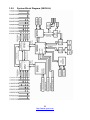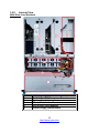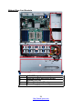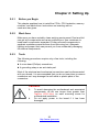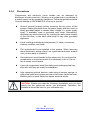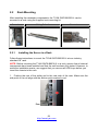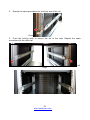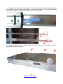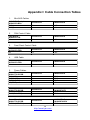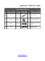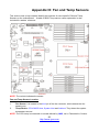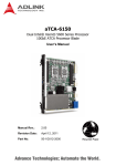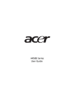
1
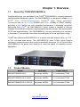
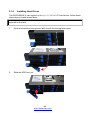
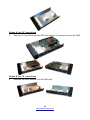
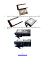
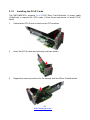
Welcome to the Iceberg Altus 2850GTi Manual GN70-B8236-IL Service Engineer’s Manual 1 http://www.tyan.com 2 http://www.tyan.com PREFACE Copyright This publication, including all photographs, illustrations, and software, is protected under international copyright laws, with all rights reserved. Neither this manual, nor any material contained herein, may be reproduced without written consent of manufacturer. ® Copyright 2011 MiTAC International Corporation. All rights reserved. TYAN is a registered trademark of MiTAC International Corporation. Version 1.0 Disclaimer Information contained in this document is furnished by MiTAC International Corporation and has been reviewed for accuracy and reliability prior to printing. MiTAC assumes no liability whatsoever, and disclaims any express or implied ® warranty, relating to sale and/or use of TYAN products including liability or warranties relating to fitness for a particular purpose or merchantability. MiTAC retains the right to make changes to produce descriptions and/or specifications at any time, without notice. In no event will MiTAC be held liable for any direct or indirect, incidental or consequential damage, loss of use, loss of data or other malady resulting from errors or inaccuracies of information contained in this document. Trademark Recognition All registered and unregistered trademarks and company names contained in this manual are property of their respective owners including, but not limited to the following. TYAN® is a trademark of MiTAC International Corporation. Intel® is a trademark of Intel® Corporation. ® ® AMI , AMIBIOS and combinations thereof are trademarks of AMI Technologies. Microsoft®, Windows® are trademarks of Microsoft Corporation. IBM®, PC®, AT® and PS/2® are trademarks of IBM Corporation. ® Winbond is a trademark of Winbond Electronics Corporation. 3 http://www.tyan.com FCC Declaration Notice for the USA Compliance Information Statement (Declaration of Conformity Procedure) DoC FCC Part 15: This device complies with part 15 of the FCC Rules This device complies with Part 15 of the FCC Rules. Operation is subject to the following conditions: This device must not cause harmful interference. This device must accept any interference received, including interference that may cause undesirable operation. This equipment has been tested and found to comply with the limits for a Class A digital device, pursuant to Part 15 of the FCC Rules. These limits are designed to provide reasonable protection against harmful interference when the equipment is operated in a commercial environment. This equipment generates, uses, and can radiate radio frequency energy and, if not installed and used in accordance with the instruction manual, may cause harmful interference to radio communications. Operation of this equipment in a residential area is likely to cause harmful interference in which case the user will be required to correct the interference at his own expense. Notice for Canada This Class A digital apparatus complies with Canadian ICES-003. Cet appareil numérique de la Classe A est conforme à la norme NMB-003 du Canada. Notice for Europe (CE Mark) This product is in conformity with the Council Directive 2004/108/EC. CAUTION: Lithium battery included with this board. Do not puncture, mutilate, or dispose of battery in fire. There will be danger of explosion if battery is incorrectly replaced. Replace only with the same or equivalent type recommended by manufacturer. Dispose of used battery according to manufacturer instructions and in accordance with your local regulations. 4 http://www.tyan.com About this Manual This manual provides you with instructions on installing your TYAN GN70-B8236-IL. This Manual is intended for experienced users and integrators with hardware knowledge of personal computers. This manual consists of the following parts: Chapter1: Provides an introduction to the TYAN GN70-B8236-IL barebones, standard parts list, describes the external components, gives a table of key components, and provides block diagram of the system. Chapter2: Covers procedures on installing the CPU, memory modules and hard drives. Chapter3: Covers removal and replacement pre-installed components. Appendix: List the cable connection and FRU part tables for reference of system setup, and technical support in case a problem arises with your system. 5 http://www.tyan.com procedures for Safety and Compliance Information Before installing and using TYAN GN70-B8236-IL, take note of the following precautions: ·Read all instructions carefully. ·Do not place the unit on an unstable surface, cart, or stand. ·Do not block the slots and opening on the unit, which are provided for ventilation. ·Only use the power source indicated on the marking label. If you are not sure, contact the power company. ·The unit uses a three-wire ground cable, which is equipped with a third pin to ground the unit and prevent electric shock. Do not defeat the purpose of this pin. If your outlet does not support this kind of plug, contact your electrician to replace your obsolete outlet. ·Do not place anything on the power cord. Place the power cord where it will not be in the way of foot traffic. ·Follow all warnings and cautions in this manual and on the unit case. ·Do not push objects in the ventilation slots as they may touch high voltage components and result in shock and damage to the components. · When replacing parts, ensure that you use parts specified by the manufacturer. ·When service or repairs have been done, perform routine safety checks to verify that the system is operating correctly. ·Avoid using the system near water, in direct sunlight, or near a heating device. ·Cover the unit when not in use. 6 http://www.tyan.com Safety Information Retain and follow all product safety and operating instructions provided with your equipment. In the event of a conflict between the instructions in this guide and the instructions in equipment documentation, follow the guidelines in the equipment documentation. Observe all warnings on the product and in the operating instructions. To reduce the risk of bodily injury, electric shock, fire and damage to the equipment, observe all precautions included in this guide. You must become familiar with the safety information in this guide before you install, operate, or service TYAN products. Symbols on Equipment Caution. This symbol indicates a potential hazard. The potential for injury exists if cautions are not observed. Consult equipment documentation for specific details. Warning. This symbol indicates the presence of hazardous energy circuits or electric shock hazards. Refer all servicing to qualified personnel. Warning. This symbol indicates the presence of a hot surface or hot component. If this surface is contacted, the potential for injury exists. To reduce risk of injury from a hot component, allow the surface to cool before touching. General Precautions · Follow all caution and warning instructions marked on the equipment and explained in the accompanying equipment documentation. Machine Room Environment · Make sure that the area in which you install the system is properly ventilated and climate-controlled. 7 http://www.tyan.com · Ensure that the voltage and frequency of your power source match the voltage and frequency inscribed on the electrical rating label of the equipment. · Do not install the system in or near a plenum, air duct, radiator, or heat register. · Never use the product in a wet location. Equipment Chassis · Do not block or cover the openings to the system. · Never push objects of any kind through openings in the equipment. Dangerous voltages might be present. · Conductive foreign objects can produce a short circuit and cause fire, electric shock, or damage to your equipment. · Lift equipment using both hands and with your knees bent. Equipment Racks To avoid injury or damage to the equipment: · Observe local occupational health and safety requirements and guidelines for manual materials handling. · Do not attempt to move a rack by yourself; a minimum of two people are needed to move a rack. · Do not attempt to move a fully loaded rack. Remove equipment from the rack before moving it. · Do not attempt to move a rack on an incline that is greater than 10 degrees from the horizontal. · Make sure the rack is properly secured to the floor or ceiling. · Make sure the stabilizing feet are attached to the rack if it is a single-rack installation. · Make sure racks are coupled together if it is a multiple-rack installation. · Make sure the rack is level and stable before installing an appliance in the rack. · Make sure the leveling jacks are extended to the floor. 8 http://www.tyan.com · Make sure the full weight of the rack rests on the leveling jacks. · Always load the rack from the bottom up. Load the heaviest component in the rack first. · Make sure the rack is level and stable before pulling a component out of the rack. · Make sure only one component is extended at a time. A rack might become unstable if more than one component is extended. To avoid damage to the equipment: · The rack width and depth must allow for proper serviceability and cable management. · Ensure that there is adequate airflow in the rack. Improper installation or restricted airflow can damage the equipment. · The rack cannot have solid or restricted airflow doors. You must use a mesh door on the front and back of the rack or remove the doors to ensure adequate air flow to the system. · If you install the Model in a rack, do not place equipment on top of the unit. It will cause restricted airflow and might cause damage to the equipment. · Make sure the product is properly matted with the rails. Products that are improperly matted with the rails might be unstable. · Verify that the AC power supply branch circuit that provides power to the rack is not overloaded. This will reduce the risk of personal injury, fire, or damage to the equipment. The total rack load should not exceed 80 percent of the branch circuit rating. Consult the electrical authority having jurisdiction over your facility wiring and installation requirements. Equipment Power Cords · Use only the power cords and power supply units provided with your system. The system might have one or more power cords. · Plug the power cord into a grounded (earthed) electrical outlet that is easily accessible at all times. · In all European electrical environments, you must ground the Green/Yellow tab on the power cord. If you do not ground the Green/Yellow tab, it can cause an electrical shock due to high leakage currents. · Do not place objects on AC power cords or cables. Arrange them so that no 9 http://www.tyan.com one might accidentally step on or trip over them. · Do not pull on a cord or cable. When unplugging from the electrical outlet, grasp the cord by the plug. · To reduce the risk of electrical shock, disconnect all power cords before servicing the appliance. Equipment Batteries · The system battery contains lithium manganese dioxide. If the battery pack is not handled properly, there is risk of fire and burns. · Do not disassemble, crush, puncture, short external contacts, or dispose of the battery in fire or water. · Do not expose the battery to temperatures higher than 60°C (140°F). · The system battery is not replaceable. If the battery is replaced by an incorrect type, there is danger of explosion. Replace the battery only with a spare designated for your product. · Do not attempt to recharge the battery. · Dispose of used batteries according to the instructions of the manufacturer. Do not dispose of batteries with the general household waste. To forward them to recycling or proper disposal, use the public collection system or return them to TYAN, your authorized TYAN partner, or their agents. Equipment Modifications · Do not make mechanical modifications to the system. TYAN is not responsible for the regulatory compliance of TYAN equipment that has been modified. Equipment Repairs and Servicing · The installation of internal options and routine maintenance and service of this product should be performed by individuals who are knowledgeable about the procedures, precautions, and hazards associated with equipment containing hazardous energy levels. · Do not exceed the level of repair specified in the procedures in the product documentation. Improper repairs can create a safety hazard. 10 http://www.tyan.com · Allow the product to cool before removing covers and touching internal components. · Remove all watches, rings, or loose jewelry when working before removing covers and touching internal components. · Do not use conductive tools that could bridge live parts. · Use gloves when you remove or replace system components; they can become hot to the touch. · If the product sustains damage requiring service, disconnect the product from the AC electrical outlet and refer servicing to an authorized service provider. Examples of damage requiring service include: – The power cord, extension cord, or plug has been damaged. – Liquid has been spilled on the product or an object has fallen into the product. – The product has been exposed to rain or water. – The product has been dropped or damaged. – The product does not operate normally when you follow the operating instructions. 11 http://www.tyan.com 12 http://www.tyan.com Table of Contents Chapter 1: Overview....................................................................... 15 1.1 About the TYAN GN70-B8236-IL ........................................... 15 1.2 Product Models....................................................................... 15 1.3 Features ............................................................................ 16 1.4 Standard Parts List ................................................................. 23 1.4.1 Box Contents ................................................................... 23 1.4.2 Accessories ..................................................................... 24 1.5 About the Product................................................................... 26 1.5.1 System Front View .......................................................... 26 1.5.2 System Rear View ........................................................... 29 1.5.3 Motherboard (S8236-IL) Layout ...................................... 30 1.5.4 Jumpers & Connectors .................................................... 31 1.5.5 System Block Diagram (S8236-IL) .................................. 32 1.5.6 Internal View.................................................................... 33 Chapter 2: Setting Up..................................................................... 35 2.0.1 Before you Begin ............................................................. 35 2.0.2 Work Area........................................................................ 35 2.0.3 Tools ................................................................................ 35 2.0.4 Precautions...................................................................... 36 2.1 Installing Motherboard Components ...................................... 37 2.1.1 Removing the Chassis Cover.......................................... 37 2.1.2 Removing the Riser Card Brackets ................................. 39 2.1.3 Installing the CPU and Heatsink...................................... 40 2.1.4 Installing the Memory ...................................................... 43 2.1.4 Installing Hard Drives ...................................................... 48 2.1.5 Installing the PCI-E Cards ............................................... 51 2.2 Rack Mounting........................................................................ 52 2.2.1 Installing the Server in a Rack......................................... 52 2.2.2 Removing the Server from a Rack ............................... 56 Chapter 3: Replacing Pre-Installed Components ........................ 57 3.1 Introduction............................................................................. 57 3.2 Disassembly Flowchart........................................................... 57 3.3 Removing the Cover............................................................... 58 3.4 Replacing Motherboard Components..................................... 58 3.4.1 Replacing PCI-E Riser Card Cards ................................. 58 3.4.2 Disconnecting All Motherboard Cables ........................... 60 3.4.3 Removing the Motherboard ............................................. 61 3.5 Replacing the Power Distribution Board................................. 62 3.6 Replacing the Front Panel Board ........................................... 63 13 http://www.tyan.com 3.6.1 Front Panel Board Specifications .................................... 65 3.6.2 FPB LED and Connector Pin Definition........................... 66 3.7 Replacing the System Fan ..................................................... 68 3.8 Replacing the Fan Backplane Board...................................... 70 3.8.1 Fan BP Board Specifications........................................... 73 3.8.2 Fan BP Board LED Definitions ........................................ 73 3.9 Replacing the HDD Backplane Board .................................... 74 3.9.1 HDD BP Board Specifications ......................................... 75 3.9.2 HDD BP Board LED Definitions ...................................... 76 Appendix I: Cable Connection Tables .......................................... 79 Appendix II: FRU Parts Table ........................................................ 81 Appendix III: Fan and Temp Sensors ........................................... 83 Appendix IV: Technical Support ................................................... 87 14 http://www.tyan.com Chapter 1: Overview 1.1 About the TYAN GN70-B8236-IL ® Congratulations on your purchase of the TYAN GN70-B8236-IL, a highly optimized rack-mountable barebone system. The GN70-B8236-IL is designed to support dual ® AMD 32nm 8-Core/12-Core/16-Core OpteronTM 6200 Series (Interlagos) Processors and up to 256GB RDIMM and 64GB UDIMM of DDR3 memory, providing a rich feature set and incredible performance. Leveraging advanced ® technology from AMD , the GN70-B8236-IL server system is capable of offering scalable 32 and 64-bit computing, high bandwidth memory design, and lightning-fast PCI-E bus implementation. The GN70-B8236-IL not only empowers your company in nowadays IT demand but also offers a smooth path for future application usage. ® TYAN also offers the GN70-B8236-IL in a version that can support up to eight 3.5” or 2.5” hot-swap hard drives. The GN70-B8236-IL uses TYAN’s latest chassis featuring a robust structure and a solid mechanical enclosure. All of this provides GN70-B8236-IL the power and flexibility to meet the needs of nowadays server application. 1.2 Product Models Model HDD Bays Power supply B8236G70W8HR-HE-IL Hot-swap, 8HDDs (1+1) redundant 770W B8236G70W8HR-HE-IL-N229 Hot-swap, 8HDDs (1+1) redundant 770W B8236G70W8HR-HE-IL-N2275 Hot-swap, 8HDDs (1+1) redundant 770W 15 http://www.tyan.com 1.3 Features TYAN GN70B8236-IL (B8236G70W8HR-HE-IL) System Front Panel External Drive Bay Form Factor Gross Weight Chassis Model Dimension (D x W x H) Motherboard Board Dimension Buttons LEDs I/O Ports Type / Q'ty Supported HDD Interface System Cooling FAN Configuration Type Efficiency Redundancy Power Supply Input Range Frequency Output Watts Processor Chipset Memory 2U Rackmount 25 kg GN70 27.56" x 17.72" x 3.43" (700 x 450 x 87mm) S8236WGM3NR-HE-IL EEB, 12"x13" (305x330mm) (1) RST / (1) ID / (1) PWR w/ LED (1) PWR / (1) ID / (1) Warning / (3) LAN (2) USB ports 2.5" or 3.5" Hot-Swap / (8) SATA-II 3.0Gb/s / SAS 6.0Gb/s (8) 6cm fans RPS1U PFC / 80 plus gold 1+1 Full-range AC(100-240V) 60 Hertz 770 Watts AMD 45nm 8-Core/12-Core Opteron 6100 Series Supported CPU Processors (Magny-Cours), AMD 32nm 8-Core Series /12-Core/16-Core Opteron 6200 Series Processors (Interlagos) Socket Type / Q'ty G34 / (2) Thermal Design 115W Power (TDP) System Bus Up to 6.4 GT/s Hyper-Transport link support Chipset AMD SR5690 + SR5650 + SP5100 Super I/O Winbond W83627DHG-P Supported DIMM (16) DIMM slots Qty U/RDDR3, LV and ULV DDR3, LRDIMM modules / DIMM Type / Design spec compliant with 1866/ 1600/ 1333/ 1066/ Speed 800 MHz Capacity Up to 256GB RDIMM/ 64GB UDIMM Memory channel 4 Channels per CPU Memory voltage 1.5V/1.35V/1.25V 16 http://www.tyan.com PCI-E Max. HBA Expansion Slots Dimension (H x L) Pre-install TYAN Riser Card Port Q'ty LAN Controller Connector type Graphic Resolution Chipset USB COM I/O Ports VGA RJ-45 Chipset System Monitoring Server Management BIOS Operating System Regulation Operating Environment RoHS (3) PCI-E Gen.2 x16 slots (6) 111.15mm x 312.00mm (FH/FL) M2201-L16-2F, PCI-E x16 2U riser card (left) / (2) M2202-R16-2F, PCI-E x16 2U riser card (right) (3) Intel 82574L / Intel 82576EB D-Sub 15-pin Up to 1600x1200@60Hz Aspeed AST2050 (4) ports (2 at front, 2 at rear) (1) DB-9 COM port (1) D-Sub 15-pin port (3) ports Winbond W83795G Monitors voltage for CPU, memory, chipset & power Voltage supply Temperature Monitors temperature for CPU & system environment Over temperature warning indicator / Fan & PSU fail LED LED indicator Others Chassis intrusion detection / Watchdog timer support Onboard Chipset Onboard Aspeed AST2050 IPMI 2.0 compliant baseboard management controller AST2050 IPMI (BMC) / Supports storage over IP and remote Feature platform-flash / BIOS update AST2050 iKVM 24-bit high quality video compression / Dual 10/100 Feature Mb/s MAC interfaces Brand / ROM size AMI / 4MB Plug and Play (PnP) /PCI2.3 /WfM2.0 /SMBIOS2.3 /PXE boot / ACPI 2.0 power management /Power on Feature mode after power recovery / User-configurable H/W monitoring / Auto-configurable of hard disk types OS supported list Please visit our Web site for the latest update. FCC (DoC) CE (DoC) Operating Temp. Non-operating Temp. In/Non-operating Humidity RoHS 6/6 Compliant Class A Yes 10° C ~ 35° C (50° F~ 95° F) - 40° C ~ 70° C (-40° F ~ 158° F) 90%, non-condensing at 35° C Yes 17 http://www.tyan.com Package Contains Barebone Heatsink / Cooler Rail kit Mounting Ear Manual Installation CD Power Cable Cord (1) GN70B8236-IL Barebone (2) G34 CPU heatsinks (1) CRAL-0031, sliding rail kit for KGT24/ KGT62 (1) mounting ear kit (1) MB User's manual + (1) BB User's manual (1) TYAN installation CD (2) CCBL-0310, US type power cord / (2) CCBL-0300, EU type power cord Optional accessories Peripheral (1) CSTK-0080, Slim type DVD kit w/cables TYAN GN70B8236-IL (B8236G70W8HR-HE-IL-N229) System Front Panel External Drive Bay Form Factor Gross Weight Chassis Model Dimension (D x W x H) Motherboard Board Dimension Buttons LEDs I/O Ports Type / Q'ty Supported HDD Interface System Cooling FAN Configuration Type Efficiency Redundancy Power Supply Input Range Frequency Output Watts Processor 2U Rackmount 25 kg GN70 27.56" x 17.72" x 3.43" (700 x 450 x 87mm) S8236WGM3NR-HE-IL EEB, 12"x13" (305x330mm) (1) RST / (1) ID / (1) PWR w/ LED (1) PWR / (1) ID / (1) Warning / (3) LAN (2) USB ports 2.5" or 3.5" Hot-Swap / (8) SATA-II 3.0Gb/s / SAS 6.0Gb/s (8) 6cm fans EPS1U PFC / 80 plus gold 1+1 Full-range AC(100-240V) 60 Hertz 770 Watts AMD 45nm 8-Core/12-Core Opteron 6100 Series Supported CPU Processors (Magny-Cours), AMD 32nm 8-Core Series /12-Core/16-Core Opteron 6200 Series Processors (Interlagos) Socket Type / Q'ty G34 / (2) Thermal Design 115W Power (TDP) System Bus Up to 6.4 GT/s Hyper-Transport link support 18 http://www.tyan.com Chipset Memory Chipset Super I/O Supported DIMM Qty DIMM Type / Speed Capacity Memory channel Memory voltage PCI-E Max. HBA Expansion Slots Dimension (H x L) Pre-install TYAN Riser Card Port Q'ty LAN Controller Connector type Graphic Resolution Chipset USB COM I/O Ports VGA RJ-45 Chipset System Monitoring Server Management BIOS Operating System AMD SR5690 + SR5650 + SP5100 Winbond W83627DHG-P (16) DIMM slots U/RDDR3, LV and ULV DDR3, LRDIMM modules / Design spec compliant with 1866/ 1600/ 1333/ 1066/ 800 MHz Up to 256GB RDIMM/ 64GB UDIMM 4 Channels per CPU 1.5V/1.35V/1.25V (3) PCI-E Gen.2 x16 slots (6) 111.15mm x 312.00mm (FH/FL) M2201-L16-2F, PCI-E x16 2U riser card (left) / (2) M2202-R16-2F, PCI-E x16 2U riser card (right) (3) Intel 82574L / Intel 82576EB D-Sub 15-pin Up to 1600x1200@60Hz Aspeed AST2050 (4) ports (2 at front, 2 at rear) (1) DB-9 COM port (1) D-Sub 15-pin port (3) ports Winbond W83795G Monitors voltage for CPU, memory, chipset & power Voltage supply Temperature Monitors temperature for CPU & system environment Over temperature warning indicator / Fan & PSU fail LED LED indicator Others Chassis intrusion detection / Watchdog timer support Onboard Chipset Onboard Aspeed AST2050 IPMI 2.0 compliant baseboard management controller AST2050 IPMI (BMC) / Supports storage over IP and remote Feature platform-flash / BIOS update AST2050 iKVM 24-bit high quality video compression / Dual 10/100 Feature Mb/s MAC interfaces Brand / ROM size AMI / 4MB Plug and Play (PnP) /PCI2.3 /WfM2.0 /SMBIOS2.3 /PXE boot / ACPI 2.0 power management /Power on Feature mode after power recovery / User-configurable H/W monitoring / Auto-configurable of hard disk types OS supported list Please visit our Web site for the latest update. 19 http://www.tyan.com Regulation Operating Environment RoHS Package Contains Optional accessories FCC (DoC) CE (DoC) Operating Temp. Non-operating Temp. In/Non-operating Humidity RoHS 6/6 Compliant Barebone Heatsink / Cooler Rail kit Mounting Ear Manual Installation CD Power Cable Cord Class A Yes 10° C ~ 35° C (50° F~ 95° F) Peripheral (1) CSTK-0080, Slim type DVD kit w/cables - 40° C ~ 70° C (-40° F ~ 158° F) 90%, non-condensing at 35° C Yes (1) GN70B8236-IL Barebone w/(2) NV M2090 cards (2) G34 CPU heatsinks (1) CRAL-0031, sliding rail kit for KGT24/ KGT62 (1) mounting ear kit (1) MB User's manual + (1) BB User's manual (1) TYAN installation CD (2) CCBL-0310, US type power cord / (2) CCBL-0300, EU type power cord TYAN GN70B8236-IL (B8236G70W8HR-HE-IL-N2275) System Front Panel External Drive Bay Form Factor Gross Weight Chassis Model Dimension (D x W x H) Motherboard Board Dimension Buttons LEDs I/O Ports Type / Q'ty Supported HDD Interface System Cooling FAN Configuration Type Efficiency Redundancy Power Supply Input Range Frequency Output Watts 2U Rackmount 25 kg GN70 27.56" x 17.72" x 3.43" (700 x 450 x 87mm) S8236WGM3NR-HE-IL EEB, 12"x13" (305x330mm) (1) RST / (1) ID / (1) PWR w/ LED (1) PWR / (1) ID / (1) Warning / (3) LAN (2) USB ports 2.5" or 3.5" Hot-Swap / (8) SATA-II 3.0Gb/s / SAS 6.0Gb/s (8) 6cm fans EPS1U PFC / 80 plus gold 1+1 Full-range AC(100-240V) 60 Hertz 770 Watts 20 http://www.tyan.com Supported CPU Series Processor Chipset Memory Socket Type / Q'ty Thermal Design Power (TDP) System Bus Chipset Super I/O Supported DIMM Qty Pre-install TYAN Riser Card Graphic I/O Ports Port Q'ty Controller Connector type Resolution Chipset USB COM VGA RJ-45 Chipset Voltage System Monitoring Temperature G34 / (2) 115W Up to 6.4 GT/s Hyper-Transport link support AMD SR5690 + SR5650 + SP5100 Winbond W83627DHG-P (16) DIMM slots U/RDDR3, LV and ULV DDR3, LRDIMM modules / Design spec compliant with 1866/ 1600/ 1333/ 1066/ 800 MHz DIMM Type / Speed Capacity Memory channel Memory voltage PCI-E Max. HBA Expansion Slots Dimension (H x L) LAN AMD 45nm 8-Core/12-Core Opteron 6100 Series Processors (Magny-Cours), AMD 32nm 8-Core /12-Core/16-Core Opteron 6200 Series Processors (Interlagos) Up to 256GB RDIMM/ 64GB UDIMM 4 Channels per CPU 1.5V/1.35V/1.25V (3) PCI-E Gen.2 x16 slots (6) 111.15mm x 312.00mm (FH/FL) M2201-L16-2F, PCI-E x16 2U riser card (left) / (2) M2202-R16-2F, PCI-E x16 2U riser card (right) (3) Intel 82574L / Intel 82576EB D-Sub 15-pin Up to 1600x1200@60Hz Aspeed AST2050 (4) ports (2 at front, 2 at rear) (1) DB-9 COM port (1) D-Sub 15-pin port (3) ports Winbond W83795G Monitors voltage for CPU, memory, chipset & power supply LED Monitors temperature for CPU & system environment Over temperature warning indicator / Fan & PSU fail LED indicator Others Chassis intrusion detection / Watchdog timer support 21 http://www.tyan.com Onboard Chipset Server Management BIOS Operating System Regulation Operating Environment RoHS Package Contains Optional accessories Onboard Aspeed AST2050 IPMI 2.0 compliant baseboard management controller AST2050 IPMI (BMC) / Supports storage over IP and remote Feature platform-flash / BIOS update AST2050 iKVM 24-bit high quality video compression / Dual 10/100 Feature Mb/s MAC interfaces Brand / ROM size AMI / 4MB Plug and Play (PnP) /PCI2.3 /WfM2.0 /SMBIOS2.3 /PXE boot / ACPI 2.0 power management /Power on Feature mode after power recovery / User-configurable H/W monitoring / Auto-configurable of hard disk types OS supported list Please visit our Web site for the latest update. FCC (DoC) CE (DoC) Operating Temp. Non-operating Temp. In/Non-operating Humidity RoHS 6/6 Compliant Barebone Heatsink / Cooler Rail kit Mounting Ear Manual Installation CD Power Cable Cord Class A Yes 10° C ~ 35° C (50° F~ 95° F) Peripheral (1) CSTK-0080, Slim type DVD kit w/cables - 40° C ~ 70° C (-40° F ~ 158° F) 90%, non-condensing at 35° C Yes (1) GN70B8236-IL Barebone w/(2) NV M2075 cards (2) G34 CPU heatsinks (1) CRAL-0031, sliding rail kit for KGT24/ KGT62 (1) mounting ear kit (1) MB User's manual + (1) BB User's manual (1) TYAN installation CD (2) CCBL-0310, US type power cord / (2) CCBL-0300, EU type power cord 22 http://www.tyan.com 1.4 Standard Parts List This section describes GN70-B8236-IL package contents and accessories. Open the box carefully and ensure that all components are present and undamaged. The product should arrive packaged as illustrated below. 1.4.1 Box Contents Component Description 2U chassis, (8) hot swap HDD bays ® TYAN S8236-IL system board (pre-installed) (1+1) ERP1U hot-swap 770W RPSU (Delta) (8) System fan M1601T70-D-PDB Power Distribution Board (pre-installed) M1245G70-BP6-STD SATA/SAS HDD Backplane Board (pre-installed) M1709G70-FPB (pre-installed) M2201-L16-2F riser card (pre-installed) M2202-R8-2F riser card (pre-installed) 23 http://www.tyan.com 1.4.2 Accessories If any items are missing or appear damaged, contact your retailer or browse to TYAN®’s website for service: http://www.tyan.com ® The web site also provides information of other TYAN products, as well as FAQs, compatibility lists, BIOS settings, etc. ® TYAN Motherboard Drive CD Heatsink x 2 HDD Screw Pack (12 pcs) Rail x 2 DVD Bracket Kit DVD Cable Kit Ventilation Bracket GPU Cable 24 http://www.tyan.com SGCC Bracket_L SGCC Bracket_R AC Power Cord 125V (US) AC Power Cord 250V (Europe) Barebone Manual Mainboard Manual Addendum for China Use Only 25 http://www.tyan.com 1.5 About the Product The following views show you the product. 1.5.1 System Front View 1 2 3 Ears 3.5” HDD bays USB Ports 4 5 6 7 8 9 10 11 ID Button NMI Button RESET Button NIC1/NIC2/NIC3 ID LED Warning LED BMC LED (reserved) Power On/OFF Button with LED 26 http://www.tyan.com LED Definitions LED Power LED NIC1 NIC2 NIC3 Warning LED ID LED State Color Description On Green System is turned on Blinking Off Blinking On off Blinking On off Blinking On off Green Off Green Green off Green Green off Green Green off On Red Off On Off Off Blue Off System is under S1 or S3 state Power off LAN active LAN linked LAN not linked LAN active LAN linked LAN not linked LAN active LAN linked LAN not linked Fan fail /Over temperature /Over voltage No failure System identified System not identified 27 http://www.tyan.com HDD LED HDD Status No Driver Present or power disconnected Driver Present No Activity Access Activity HDD Fail Identify (Locate the HDD) SAS/SATA RAID Rebuilding Status LED Color: Amber OFF OFF OFF Solid ON Blinking @1Hz Blinking @4Hz 28 http://www.tyan.com Activity LED Color: Green OFF Solid ON Blinking OFF OFF OFF 1.5.2 System Rear View 1 2 3 4 5 6 7 Power Supply LAN3 (shared with IPMI) + 2 USB COM Port LAN1 + LAN2 ID LED VGA Port PCI-E Slots LAN LED LED RJ-45 Activity(left) State On Green Blinking Green On Flash Green Amber On Green Disabled RJ-45 Linkage(Right) Color Description 10Mb/100Mb/1000Mb linked 10Mb/100Mb/1000Mb activity No LAN linked 1000Mb linked 100Mb linked 10Mb mode or No LAN Disabled Off linked NOTE: “Left” and “Right” are viewed from the rear panel. ID LED LED ID LED State On Off Color Blue Off Description System identified System not identified 29 http://www.tyan.com 1.5.3 Motherboard (S8236-IL) Layout The diagram is representative of the latest board revision available at the time of publishing. The board you receive may not look exactly like the above diagram. 30 http://www.tyan.com 1.5.4 Jumpers & Connectors Jumper/Connector J4 J5/J12/J30/J34/J54/J55/J56 J23 J24 J25 J28 J29/J33 J31 J32 J53 J59 JP1/JP2 JP3 JP6 JP7 LED1 LED2 LED3 LED4 LED5 LED6 LED7 LED8 Function COM2 Header 4-pin Fan Connectors Front Panel Header Reset Switch Power Switch Fan TACH Connector USB Front Panel Header PSMI Connector LAN3 Active LED Header HDD Fault Header IPMB Header COM2 Function Select Jumper Clear CMOS Jumper Front Panel ID LED Button Chassis Intrusion Header ID LED SAS Flash Ready (Amber) SAS HD Fault LED (Amber) Power On LED (Green) Standby LED (Green) SAS Error LED (Amber) SAS Heart Beat LED (Green) BMC Heart Beat LED (Green) Jumper Legend OPEN - Jumper OFF Without jumper cover CLOSED - Jumper ON With jumper cover 31 http://www.tyan.com 1.5.5 System Block Diagram (S8236-IL) 32 http://www.tyan.com 1.5.6 Internal View With Riser Card Brackets 1 2 3 4 5 6 3.5” HDD cage (underneath) SAS/SATA HDD Backplane Board System Fan Unit Power Distribution Board PCI-E Riser Card Bracket Power Supply (underneath) 33 http://www.tyan.com Without Riser Card Brackets 1 2 3 4 5 3.5” HDD cage (underneath) SAS/SATA HDD Backplane Board System Fan Unit Power Distribution Board Power Supply (underneath) 34 http://www.tyan.com Chapter 2: Setting Up 2.0.1 Before you Begin This chapter explains how to install the CPUs, CPU heatsinks, memory modules, and hard drives. Instructions on inserting add on cards are also given. 2.0.2 Work Area Make sure you have a stable, clean working environment. Dust and dirt can get into components and cause malfunctions. Use containers to keep small components separated. Putting all small components in separate containers prevents them from becoming lost. Adequate lighting and proper tools can prevent you from accidentally damaging the internal components. 2.0.3 Tools The following procedures require only a few tools, including the following: A cross head (Phillips) screwdriver A grounding strap or an anti-static pad Most of the electrical and mechanical connections can be disconnected with your hands. It is recommended that you do not use pliers to remove connectors as it may damage the soft metal or plastic parts of the connectors. Caution! 1. 2. To avoid damaging the motherboard and associated components, do not use torque force greater than 7kgf/cm (6.09 lb/in) on each mounting screw for motherboard installation. Do not apply power to the board if it has been damaged. 35 http://www.tyan.com 2.0.4 Precautions Components and electronic circuit boards can be damaged by discharges of static electricity. Working on a system that is connected to a power supply can be extremely dangerous. Follow the guidelines below to avoid damage to GN70-B8236-IL or injury to yourself. Ground yourself properly before removing the top cover of the system. Unplug the power from the power supply and then touch a safely grounded object to release static charge (i.e. power supply case). If available, wear a grounded wrist strap. Alternatively, discharge any static electricity by touching the bare metal chassis of the unit case, or the bare metal body of any other grounded appliance. Avoid touching motherboard components, IC chips, connectors, memory modules, and leads. The motherboard is pre-installed in the system. When removing the motherboard, always place it on a grounded anti-static surface until you are ready to reinstall it. Hold electronic circuit boards by the edges only. Do not touch the components on the board unless it is necessary to do so. Do not flex or stress circuit boards. Leave all components inside the static-proof packaging that they ship with until they are ready for installation. After replacing optional devices, make sure all screws, springs, or other small parts are in place and are not left loose inside the case. Metallic parts or metal flakes can cause electrical shorts. CAUTION: Please note that the following illustrations may not look exactly like the rackmount server you purchased. Therefore, the illustrations should be held for your reference only. 36 http://www.tyan.com 2.1 Installing Motherboard Components This section describes how to install components on to the motherboard, including CPUs, memory modules, HDD and PCI-E cards. 2.1.1 Removing the Chassis Cover Follow these instructions to remove the GN70-B8236-IL chassis cover. 1 Unscrew the rear top cover on the back side. 2 Unscrew the front top cover and pull the latches aside to lift up the top cover. 37 http://www.tyan.com 3 Slide the rear top cover out. 38 http://www.tyan.com 2.1.2 Removing the Riser Card Brackets Follow these instructions to remove the PCI-E Riser Card Brackets. 1 Loose four thumb screws to release the PCI-E Riser Card Brackets. 2 Lift up the Riser Card Brackets. 39 http://www.tyan.com 2.1.3 Installing the CPU and Heatsink Follow the steps below on installing CPUs and CPU heatsinks. 1. Locate the CPU sockets. 2. Pull the lever slightly away from the socket and then push it to a fully open position. 3. Push the CPU socket cover to a fully open position. 40 http://www.tyan.com 4. Take out the protection cap. 5. Place the CPU into the socket and make sure that the gold arrow is located in the right direction. 6. CPU. Close the CPU socket cover and press the lever down to secure the 41 http://www.tyan.com 7. Position the heatsink on top of the CPU and secure it with 2 screws. 8. heatsink. Repeat the procedures mentioned earlier to install the second CPU and 42 http://www.tyan.com 2.1.4 Installing the Memory Follow these instructions to install the memory modules onto the motherboard. 1. Locate the memory slots on the motherboard. 2. Press the memory slot locking levers in the direction of the arrows as shown in the following illustration. 3. Align the memory module with the slot. When inserted properly, the memory slot locking levers lock automatically onto the indentations at the ends of the module. Follow the recommended memory population table to install the other memory modules. 43 http://www.tyan.com Memory Population Option Table The following pictures show common types of DDR3 memory modules. 44 http://www.tyan.com Recommended Memory Population Table Single CPU Installed (CPU0 only) Quantity of memory installed 1 2 3 4 Dual CPU installed (CPU0 and CPU1) 6 CPU0_DIMM(1)D0 2 3 4 5 6 7 8 10 √ CPU0_DIMM(2)D1 √ √ CPU0_DIMM(3)C0 √ √ √ √ √ CPU0_DIMM(4)C1 √ √ CPU0_DIMM(5)B0 CPU0_DIMM(6)B1 √ √ √ CPU0_DIMM(7)A0 CPU0_DIMM(8)A1 8 √ √ √ √ √ √ √ √ √ √ √ √ √ √ √ √ √ √ √ √ √ √ √ √ √ √ √ √ √ √ 12 14 16 √ √ √ √ √ √ √ √ √ √ √ √ √ √ √ √ √ √ √ √ √ √ √ √ √ √ √ √ √ √ √ √ √ √ √ √ √ √ √ √ √ √ √ √ CPU1_DIMM(9)D0 √ CPU1_DIMM(10)D1 CPU1_DIMM(11)C0 √ √ CPU1_DIMM(12)C1 √ √ √ √ √ CPU1_DIMM(13)B0 CPU1_DIMM(14)B1 √ √ √ √ √ √ √ √ √ √ √ √ √ √ CPU1_DIMM(15)A0 CPU1_DIMM(16)A1 √ √ NOTE: 1. √ indicates a populated DIMM slot. 2. Paired memory installation for Max performance. 3. Populate the same DIMM type in each channel, specifically - Use the same DIMM size - Use the same # of ranks per DIMM 4. Dual-rank DIMMs are recommended over single-rank DIMMs 5. Un-buffered DIMM can offer slightly better performance than registerd DIMM if populating only a single DIMM per channel 6. We don't suggest other memory installation. 7. AMD 6100/6200 series CPU doesn't support Quad-ranks U-DIMM 45 http://www.tyan.com U-DIMM Module Support DDR3 Speed/Voltage NOTE: DDR3 Rank Configuration 1.25v 1.35v 1.5v DIMM1 (A1, B1, C1, D1) DIMM0 (A0, B0, C0, D0) 800MHz 800MHz 800MHz SR and DR n/a 800MHz 800MHz 800MHz SR and DR SR and DR 1066MHz 1066MHz 1066MHz SR and DR n/a 1066MHz 1066MHz 1066MHz SR and DR SR and DR 1333MHz n/a n/a SR and DR n/a 1333MHz n/a n/a SR SR n/a 1333MHz 1333MHz SR and DR n/a n/a 1333MHz 1333MHz SR and DR SR and DR n/a n/a 1600MHz SR and DR n/a n/a n/a 1600MHz SR SR U-DIMM can support up to 4GB sized DIMM’s Maximum of 8GB per channel SR and DR UDDR3 module support only x8 DRAM module support only SR and DR 1.25v Memory MAX speed of 1333MHz in a dual channel configuration SR and DR 1.35v Memory MAX speed of 1333MHz in a dual channel configuration SR and DR 1.5v Memory MAX speed of 1600MHz in a dual channel configuration 46 http://www.tyan.com R-DIMM Module Support DDR3 Speed/Voltage NOTE: DDR3 Rank Configuration 1.25v 1.35v 1.5v DIMM1 (A1, B1, C1, D1) DIMM0 (A0, B0, C0, D0) 800MHz 800MHz 800MHz SR,DR and QR n/a 800MHz 800MHz 800MHz SR,DR and QR SR,DR and QR 1066MHz 1066MHz n/a SR,DR and QR n/a 1066MHz 1066MHz n/a SR and DR SR and DR n/a n/a 1066MHz SR,DR and QR n/a n/a n/a 1066MHz SR,DR and QR SR,DR and QR 1333MHz n/a n/a SR and DR n/a 1333MHz n/a n/a SR SR n/a 1333MHz n/a SR and DR n/a n/a 1333MHz n/a SR and DR SR and DR n/a n/a 1333MHz SR,DR and QR n/a n/a n/a 1333MHz SR and DR SR and DR n/a n/a 1600MHz SR and DR n/a n/a n/a 1600MHz SR SR RDIMM can support up to 16GB sized DIMM’s SR and DR Memory has a MAX amount of 16GB per channel SR and DR 1.25v Memory MAX speed of 1333MHz in a dual channel configuration SR and DR 1.35v Memory MAX speed of 1333MHz in a dual channel configuration SR and DR 1.5v Memory MAX speed of 1600MHz in a dual channel configuration QR Memory has a MAX amount of 32GB per channel QR 1.25v Memory MAX speed of 1066MHz in a dual channel configuration QR 1.35v Memory MAX speed of 1066MHz in a dual channel configuration QR 1.5v Memory MAX speed of 1333MHz in a dual channel configuration 47 http://www.tyan.com 2.1.4 Installing Hard Drives The GN70-B8236-IL can support up to eight (8) 3.5” or 2.5” hard drives. Follow these instructions to install a hard drive. Warning!!! Always install the hard disk drive to the chassis after the chassis is secured on the rack. 1 Press and hold the locking lever latch to pull the locking lever open. 2 Slide the HDD tray out. 48 http://www.tyan.com Option A: for 2.5” hard drives 3 Place a 2.5” hard drive into the HDD tray and use 4 screws to secure the HDD. Option B: for 3.5” hard drives 4 Unscrew the drive bracket from the HDD tray. 49 http://www.tyan.com 5 Place a 3.5” hard drive into the drive tray and use 6 screws to secure the HDD. 6 Reinsert the HDD tray into the chassis and press the locking lever to secure the tray. 50 http://www.tyan.com 2.1.5 Installing the PCI-E Cards The GN70-B8236-IL supports three PCI-E Riser Card Brackets. A power cable (2x3p/2x4p) is required for GPU cards. Follow these instructions to install PCI-E cards. 1 Unscrew the PCI-E slots to take out the PCI brackets. 2 Insert the PCI-E cards and securely screw as shown. 3 Repeat the same procedures for the second and third Riser Card Brackets. 51 http://www.tyan.com 2.2 Rack Mounting After installing the necessary components, the TYAN GN70-B8236-IL can be mounted in a rack using the supplied rack mounting kit. Rear view 2.2.1 Sliding Rail x 2 Front view Installing the Server in a Rack Follow these instructions to mount the TYAN GN70-B8236-IL into an industry standard 19” rack. NOTE: Before mounting the TYAN GN70-B8236-IL in a rack, ensure that all internal components have been installed and that the unit has been fully tested. However, to make the installation easier, we suggest that you remove all HDD trays before you insert the chassis to the rack. 1. Position the rear of the sliding rail to the rear side of the rack. Make sure the mid-point of the rail align with the anchor point marked in red. Rear 52 http://www.tyan.com 2. Repeat the same procedures for the front end of the rail. Front 3. Push the locking latch to secure the rail to the rack. Repeat the same procedures for the other rail. Left Right 53 http://www.tyan.com 4. Slide the inner rail to its full length. Note that to slide to its full length, push the locking tab of the rail upward and then the rail can slide freely. There are three holes on each rail which are used to hook and secure the chassis. 5. Align the studs on the chassis with the holes on the rails and make sure the chassis is securely hooked. 54 http://www.tyan.com 6. Push the chassis back into the rack. 7. The installation is now complete. 55 http://www.tyan.com 2.2.2 Removing the Server from a Rack Follow these instructions to remove the TYAN GN70-B8236-IL from an industry standard 19” rack. 1. Push the ears to pull the chassis forward. 2. Push forward the locking tabs on both rails to unhook the chassis from the rails. 3. Follow the steps described earlier in reverse to remove the chassis from the rack. NOTE: To avoid injury, it is strongly recommended that at least two people lift the TYAN GN70-B8236-IL to hook on or unhook from the rails. 56 http://www.tyan.com Chapter 3: Replacing Pre-Installed Components 3.1 Introduction This chapter explains how to replace the pre-installed components, including the S8236-IL Motherboard, M1709G70-FPB Front Panel Board, PCI-E Riser Card, M1245G70-BP6-8 SATA/SAS HDD Board, System Fan and Power Supply Unit etc. 3.2 Disassembly Flowchart The following flowchart outlines the disassembly procedure. 57 http://www.tyan.com 3.3 Removing the Cover Before replacing any parts you must remove the chassis cover. Follow Section 2.1.1 Removing the Chassis Cover (page 37) to remove the cover of the GN70-B8236-IL. 3.4 Replacing Motherboard Components Follow these instructions to replace motherboard components, including the motherboard. 3.4.1 Replacing PCI-E Riser Card Cards The GN70-B8236-IL has three pre-installed PCI-E×16 riser cards. Follow the instructions below to disassemble the M2201-L16-2F and M2202-F16-2F PCI-E riser cards. 1 Unscrew to take out the PCI-E cards. 2 Unscrew the M2201-L16-2F riser card to replace a new one if necessary. 58 http://www.tyan.com 3 Repeat the same procedures for the second and third Riser Card Brackets. 4 Unscrew the M2202-F16-2F riser card to replace a new one if necessary. 59 http://www.tyan.com 3.4.2 Disconnecting All Motherboard Cables Before replacing the motherboard or certain components, remove cables connected to the motherboard. Follow these instructions to remove all cables. 1 Disconnect the power and PSMI cables. 2 Disconnect the Mini SAS, USB, fan control and front panel cables. 3 Disconnect the power cable. 60 http://www.tyan.com 3.4.3 Removing the Motherboard After removing all of the aforementioned cables, follow the instructions below to remove the motherboard from the chassis. 1 2 Remove the heatsinks and processors if installed. Remove the nine screws securing the motherboard to the chassis. 3 Carefully lift the motherboard from the chassis. 61 http://www.tyan.com 3.5 Replacing the Power Distribution Board Follow these instructions to replace the M1601T70-D-PDB power distribution board. 1 Disconnect all cables. 2 Unscrew to replace a new power distribution board. 62 http://www.tyan.com 3.6 Replacing the Front Panel Board Follow these instructions to replace the M1709G70-FPB Front Panel Board. 1 Unscrew to release the Front Panel Board Module. 2 Push the Front Panel Board Module forward. 3 Disconnect the Front Panel Control and USB cables. 4 Unscrew the Front Panel Board to replace a new one. 63 http://www.tyan.com 5 Follow the steps described earlier in reverse to reinstall the Front Panel Board. 64 http://www.tyan.com 3.6.1 Front Panel Board Specifications Form Factor Connectors LEDs Push buttons 18.5MMx44.2MM, 4-Layer PCB One 2x15 pin header for front panel connector of motherboard and HDD backplane board Power On/Off LED Color: Green (after power on) ID LED Color: Blue Warning (IPMI) LED Dual Color: Yellow (Warning) / Green(Normal) RESET button ID button Power On/Off button with Power On/Off LED 65 http://www.tyan.com 3.6.2 FPB LED and Connector Pin Definition LED Power On/Off LED Warning (IPMI) LED ID LED State Color Description On Green System is turned on Blinking Off Green Off On Orange On Green On Blue Off Off System is under S1 or S3 state Power off Fan fail / Over temperature / Over Voltage / PSU fail No failure System identified remotely on the server, by clicking the Chassis Locate LED key.* System not identified *: For more information on the Chassis Locate LED, please visit our Web site for the latest Pilot II Software Configuration Guide. Front Panel Connector (J3) Definition PW_LED+ Key PW_LEDHD/LAN3_LED+ HD/LAN3_LEDPWR_SW+ PWR_SWRESET+ RESETID_SW+ Temp_sensor EXT_INT Pin 1 3 5 7 9 11 13 15 17 19 21 23 Pin 2 4 6 8 10 12 14 16 18 20 22 24 Definition VCC ID_LED+ ID_LEDSYS_FAULT1SYS_FAULT2LAN1_LED+ LAN1_LEDICH_SMBDAT ICH_SMBCLK INTRU# LAN2_LED+ LAN2_LED- 66 http://www.tyan.com USB Connector (J1) Definition VCC USB1USB1+ GND KEY Pin 1 3 5 7 9 Pin 2 4 6 8 10 Definition VCC USB2USB2+ GND GND 67 http://www.tyan.com 3.7 Replacing the System Fan Follow these instructions to replace the system fan. 1 Press the latch in the direction as shown to lift up the fan from cage. 2 Take out the fan unit. 3 Loose the screws on both sides. 4 Push the latch in the direction as the arrow shown to release the fan from the iron holder. 68 http://www.tyan.com 5 Remove the iron holder to replace a new fan. 6 After replacing a new one, put the fan unit back into the cage. 69 http://www.tyan.com 3.8 Replacing the Fan Backplane Board Follow these instructions to replace the Fan Backplane Board in your system. 1 Press the latch in the direction as shown to lift up the fan from cage. 2 Remove all eight fans from the chassis. 70 http://www.tyan.com 3 Disconnect all cables attached to the Fan Backplane Board. 4 Use a screw driver to unscrew the Fan Module. 5 Disconnect the power and fan cables. 6 Lift up the Fan Module. 71 http://www.tyan.com 7 Release the 14 screws on the Fan Backplane Board to replace a new one. 8 Follow the steps described in reverse order to reinstall the fan cage. 72 http://www.tyan.com 3.8.1 Fan BP Board Specifications Form Factor Integrated I/O 3.8.2 254 mm x 82 mm, 4-layer PCB (2) 1x4pin R/A Power Connector (8) 2x2pin Fan Connectors (1) 2 x10pin Barebone Fan Connector (1) 2x2pin Connector for S7015 Fan BP Board LED Definitions FAN Status Green LED Red LED With Fan On Off Without Fan Off On 73 http://www.tyan.com 3.9 Replacing the HDD Backplane Board Follow these instructions to replace the SATA/SAS HDD Backplane Board. 1 Refer to Section 3.8 Replacing the Fan Backplane Board for how to remove the Fan Module. Disconnect the power cables attached to the HDD BP Board. 2 Unscrew the HDD BP Board. Remove the HDD BP Board from the hook. 3 Replace a new HDD BP Board and reinstall it into the chassis following the steps in reverse. 74 http://www.tyan.com 3.9.1 HDD BP Board Specifications Front View Rear View (with mylar) Form Factor Integrated I/O LEDs 81.8 x 436 mm, 4-layer PCB 8 SAS HDD Connectors 2 Mini SAS Connectors to MB and RAID Card 1 2 x 4-pin Power Connector 8 HDD active LEDs 8 HDD fault LEDs PW3 Pin definition Definition GND GND GND GND Pin 1 2 3 4 Pin 5 6 7 8 75 http://www.tyan.com Definition +12V +12V +12V +12V 3.9.2 HDD BP Board LED Definitions HDD Status Status LED Activity LED Color: Amber Color: Green No Driver Present or power disconnected OFF OFF Driver Present No Activity OFF ON Access Activity OFF Blinking HDD Fail On Solid OFF Identify (Locate the HDD) Blinking(4Hz) x SAS/SATA RAID Rebuilding Blinking(1Hz) x NOTE: If the LSI 9280-l6i4e or 9260-l6i storage cards is installed, the LED status will change as below: Identify (Locate the HDD) Blinking(4Hz) ON SAS/SATA RAID Rebuilding Blinking Blinking 76 http://www.tyan.com 3.10 Replacing the Power Supply 1 Press and hold the latch to pull the power supply out. 2 After replacing a new power supply, press and hold the latch to push the power supply back into the chassis. 77 http://www.tyan.com NOTE 78 http://www.tyan.com Appendix I: Cable Connection Tables 1. Mini-SAS Cables SAS/SATA Backplane M1245G70-BP6 SAS_1 SAS_2 2. Connects to Motherboard J28 Connects to Motherboard J23 USB Cable Front Panel Board M1709G70-FPB J1 5. J17 J11 Front Panel Control Cable Front Panel Board M1709G70-FPB J3 4. Motherboard FAN Control Cable FAN Board M1806G70-FB J8 3. Connects to Connects to Motherboard J33 Connects to Motherboard PW1 PW2 PW3 J31 Power Cables Power Board M1601T70-D-PDB PW1 (MB) PATX1 (MB1) PATX2 (MB2) J7 (PSMI) Power Board M1601T70-D-PDB PW4 (FAN BD1) PW5 (FAN BD2) Power Board M1601T70-D-PDB PATX8 (HDD BP3) Connects to Connects to 79 http://www.tyan.com FAN Board M1806G70-FB PW2 PW1 SAS/SATA Backplane M1245G70-BP6 PW1 80 http://www.tyan.com Appendix II: FRU Parts Table KGN70 Chassis Kit FRU Parts Item Model Number Part Number Picture Power Supply CPSU-0470 471015200243 2 DELTA, DPS-770CB,1U FAN CFAN-0330 336252012309 8 12000RPM,60*60*38MM,4PIN Cable CCBL-0300 332810000281 1 A/C POWER CORD, L=1830MM, EU TYPE Cable CCBL-0317 332810000397 1 PWR CORD; US, 125V, 18AWGX3C, L:1800MM 81 http://www.tyan.com Quantity Description NOTE 82 http://www.tyan.com Appendix III: Fan and Temp Sensors This section aims to help readers identify the locations of some specific FAN and Temp Sensors on the motherboard. A table of BIOS Temp sensor name explanation is also included for readers’ reference. NOTE: The red dot indicates the sensor. Fan and Temp Sensor Location: 1. Fan Sensor: It is located in the third pin of the fan connector, which detects the fan 2. Temp Sensor: CPU0 MOS Area, System Inlet and Ambient. They detect the system speed (rpm). temperature around. NOTE: The CPU temp is measured on a scale defined by AMD, not in Fahrenheit or Celsius. 83 http://www.tyan.com BIOS Temp Sensor Name Explanation: 84 http://www.tyan.com BIOS Temp Sensor Name Explanation CPU0 Temp Temperature of CPU0 CPU1 Temp Temperature of CPU1 CPU0 MOS Area Temperature of the CPU0 MOS Area SR5690 Case Temperature of the SR5690 Chipset SR5650 Case Temperature of the SR5650 Chipset SAS Case Temperature of the SAS Chipset System Inlet Temperature of the System Air Inlet Area Ambient Temperature of the sensor built in the Front Panel Connector (It displays the system temp only when the FP cable is connected.) MB: the sensor reads “N/A” 0 BB: the sensor reads the system temperature around ( C) NOTE: If the GPU Card is not installed, the temp sensor will read “N/A”. GPU Card 1 Temp Temperature of GPU Card 1 GPU Card 2 Temp Temperature of GPU Card 2 NOTE: If the DIMM slot is not populated, the temp sensor will read “N/A”. CPU0 DIMM A0 Temperature of CPU0 DIMM A0 Slot 85 http://www.tyan.com CPU0 DIMM A1 Temperature of CPU0 DIMM A1 Slot CPU0 DIMM B0 Temperature of CPU0 DIMM B0 Slot CPU0 DIMM B1 Temperature of CPU0 DIMM B1 Slot CPU0 DIMM C0 Temperature of CPU0 DIMM C0 Slot CPU0 DIMM C1 Temperature of CPU0 DIMM C1 Slot CPU0 DIMM D0 Temperature of CPU0 DIMM D0 Slot CPU0 DIMM D1 Temperature of CPU0 DIMM D1 Slot CPU1 DIMM A0 Temperature of CPU1 DIMM A0 Slot CPU1 DIMM A1 Temperature of CPU1 DIMM A1 Slot CPU1 DIMM B0 Temperature of CPU1 DIMM B0 Slot CPU1 DIMM B1 Temperature of CPU1 DIMM B1 Slot CPU1 DIMM C0 Temperature of CPU1 DIMM C0 Slot CPU1 DIMM C1 Temperature of CPU1 DIMM C1 Slot CPU1 DIMM D0 Temperature of CPU1 DIMM D0 Slot CPU1 DIMM D1 Temperature of CPU1 DIMM D1 Slot PSU1 Temp Temperature of Power Supply #1 (PSU1) PSU2 Temp Temperature of Power Supply #2 (PSU2) 86 http://www.tyan.com Appendix IV: Technical Support If a problem arises with your system, you should first turn to your dealer for direct support. Your system has most likely been configured or designed by them and they should have the best idea of what hardware and software your system contains. Hence, they should be of the most assistance for you. Furthermore, if you purchased your system from a dealer near you, take the system to them directly to have it serviced instead of attempting to do so yourself (which can have expensive consequence). If these options are not available for you then MiTAC International Corporation can help. Besides designing innovative and quality products for over a decade, MiTAC has continuously offered customers service beyond their expectations. TYAN’s website (http://www.tyan.com) provides easy-to-access resources such as in-depth Linux Online Support sections with downloadable Linux drivers and comprehensive compatibility reports for chassis, memory and much more. With all these convenient resources just a few keystrokes away, users can easily find their latest software and operating system components to keep their systems running as powerful and productive as possible. MiTAC also ranks high for its commitment to fast and friendly customer support through email. By offering plenty of options for users, MiTAC serves multiple market segments with the industry’s most competitive services to support them. Please feel free to contact us directly for this service at [email protected] Help Resources: 1. See the beep codes section of this manual. 2. See the TYAN’s website for FAQ’s, bulletins, driver updates, and other information: http://www.tyan.com 3. Contact your dealer for help before calling TYAN. 4. Check the TYAN user group: alt.comp.periphs.mainboard.TYAN 87 http://www.tyan.com Returning Merchandise for Service During the warranty period, contact your distributor or system vendor FIRST for any product problems. This warranty only covers normal customer use and does not cover damages incurred during shipping or failure due to the alteration, misuse, abuse, or improper maintenance of products. NOTE: A receipt or copy of your invoice marked with the date of purchase is required before any warranty service can be rendered. You may obtain service by calling the manufacturer for a Return Merchandise Authorization (RMA) number. The RMA number should be prominently displayed on the outside of the shipping carton and the package should be mailed prepaid. TYAN will pay to have the board shipped back to you. TYAN® GN70-B8236-IL Service Engineer’s Manual V1.00 Document No.: D2153-100 88 http://www.tyan.com