1
Application Note
Data Transfer between Serial Link and TCP/IP
Link Using eZ80F91 MCU
AN021904–0808
Abstract
This application note describes Zilog’s eZ80 ®based Serial-to-TCP and TCP-to-Serial communicator that transfers data between a serial RS-232
link and a TCP/IP link. The communicator application, powered by eZ80F91 MCU and running
the Zilog TCP/IP (ZTP) Software Suite, accepts
incoming data from the Internet (or LAN), and
sends it to a serial port. This communicator application is also capable of uploading serial data to
the Internet (or LAN).
Notes: 1. The source code file associated
w it h t h i s a p p l i c a ti o n n o t e ,
AN0219-SC01.zip, is available for download at
www.zilog.com.
2. The source code associated with
this document is intended for use
with Zilog TCP/IP Software Suite
version 2.1 (ZTP v2.1) and Zilog
Developer Studio II–IDE for
eZ80Acclaim!® version 4.11
(ZDS II v4.11).
Zilog® Product Overview
This section provides a brief overview of Zilog
products used in this application note, which
includes the eZ80AcclaimPlus!™ microcontrollers
and the full-feature ZTP software suite.
eZ80F91, eZ80F92, and eZ80F93, are an exceptional value for customers designing high performance embedded applications. With speeds up to
50 MHz and an on-chip Ethernet MAC (eZ80F91
only), you have the performance necessary to
execute complex applications supporting networking functions quickly and efficiently. Combining
on-chip Flash and SRAM, eZ80AcclaimPlus!
devices provide the memory required to implement communication protocol stacks and achieve
flexibility when performing in-system updates of
application firmware.
Zilog also offers two eZ80® devices without Flash
memory: eZ80L92 and eZ80190 microprocessors.
ZTP Overview
ZTP integrates a rich set of networking services
with an efficient real-time operating system
(RTOS). The operating system is a compact preemptive multitasking, multi threaded kernel with
inter-process communications (IPC) support and
soft real-time attributes.
Table 1 lists the standard network protocols
implemented as part of the embedded TCP/IP
protocol stack in ZTP.
Table 1. Standard Network Protocols in ZTP
HTTP
TFTP
SMTP
DHCP
DNS
ICMP
IGMP
Telnet
IP
PPP
TIMEP SNMP
TCP
UDP
ARP
FTP
SNTP
RARP
eZ80AcclaimPlus! MCU Family
Overview
SSL
The eZ80AcclaimPlus! family of microcontrollers
includes Flash and non-Flash products. The Flashbased eZ80AcclaimPlus! MCUs, device numbers
Many TCP/IP application protocols are designed
using the client-server model. The final stack size
Copyright ©2008 by Zilog®, Inc. All rights reserved.
www.zilog.com
Data Transfer between Serial Link and TCP/IP Link Using eZ80F91 MCU
ets offering greater reliability in terms of communication. However, a remote device featuring a
UART communications port can contain information that can be processed by another external processing device, such as a CPU.
is link-time configurable and determined by the
protocols included in the build.
Discussion
The Serial-to-TCP and TCP-to-Serial communicator application provides an excellent interface for
controlling web-enabled devices. Web-enabling a
device that serves as a source of data to an external
processing device is convenient via the internet.
This method of communication provides a connectivity between serial devices and the Internet.
Often, web-enabled devices output data through a
serial UART-compatible channel. This data output
can be a continuous stream, or series of data pack-
Sending information to this external processing
device can be accomplished by using a
web-enabling device such as a Serial-to-TCP
interface. This method of information transfer
results in a throughput performance that offers a
significant improvement over current communication methods, such as modems or low-end ISDN.
(Integrated Services Digital Network)
RS-232
HyperTerminal
UART
Driver
HTML Page
TCP/IP
CGI Function
Kernel
TCP/IP
Kernel (RZK)
TCP Connection
PC
eZ80F91 Mini E-NET Module (eZ80F915005MODG)
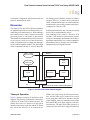
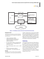
Figure 1. Serial-to-TCP Interface Block Diagram
Theory of Operation
Figure 1 displays a Serial-to-TCP interface block
diagram. This Serial-to-TCP interface functions as
a Serial-to-TCP and TCP-to-Serial converter. The
eZ80® device acts as a webserver to provide an
interface between the serial link and the TCP link.
One end of the eZ80 device is connected to a
AN021904–0808
HTML (web) page using the CGI function interface, and the other end is connected to a serial
device using the UART driver interface. One end
of the eZ80F91 webserver transmits/receives data
from the HTML (web) page using the CGI function interface. The other end of this webserver is
connected to the serial device (HyperTerminal) to
Page 2 of 9
Data Transfer between Serial Link and TCP/IP Link Using eZ80F91 MCU
transmit and receive data from this end, using the
UART driver interface.
Developing the Communicator
Application
This section discusses the software implementation for the Serial-to-TCP and TCP-to-Serial
communicator application.
Software Implementation
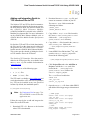
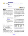
Figure 2 displays a software flow control diagram
illustrating the main function block for the Serialto-TCP interface. The Serial-to-TCP and TCP-toSerial communicator application is implemented
in two software modules: Serial Interface Module
and TCP Interface Module.
Serial Interface Module
The serial interface module uses the HyperTerminal application as a serial input/output device.
Whenever you press a key, the Serial Read thread
continuously reads the data from the UART driver
and stores this data in the Current buffer. If the
Current buffer is full or if you hit the Enter key,
this data is transferred from the Current buffer to
the TCP buffer. The TCP window reads the data
from the TCP buffer and updates the Serial Read
window. The data-upload CGI function uploads
the data to the HTML page after receiving
repeated requests from the browser.
TCP Interface Module
The TCP interface module uses the TCP window
(HTML web page) which contains two separate
windows for writing and reading data. After you
click the Submit button, the TCP Write window
transfers the data to the buffer using the CGI function interface. The TCP Read window is updated
automatically and continuously.
The TCP-to-serial CGI function interface reads
the data from the HTML page on receiving a
request from the browser. This browser request is
generated after you click the Submit button at the
TCP Write window. The browser request updates
the serial buffer with the current received data,
and uploads the data to the serial driver for transmission over the serial link (HyperTerminal in this
case).
HTML
HyperTerminal Window
Write
Window
Read
Window
UART Driver Interface
(UART0)
Buffer Management
Current
Buffer
Old
Buffer
CGI Functions
Input
CGI
Output
CGI
TCP/IP Stack Running the eZ80 Web Server
Figure 2. Software Flow Control Diagram
AN021904–0808
Page 3 of 9
Data Transfer between Serial Link and TCP/IP Link Using eZ80F91 MCU
Adding and Integrating Serial-toTCP Interface Files to ZTP
The Serial-to-TCP and TCP-to-Serial communicator application described in this document requires
the ZTP Software Suite, the interface board, and
the eZ80F91 Mini Ethernet Module
(eZ80F915005MOD) included in the eZ80F91
Modular Development Kit. For more information
on the eZ80F91 Mini Ethernet Module, refer to
eZ80F91 Mini Enet Module Product Specification
(PS0236).
For Serial-to-TCP and TCP-to-Serial functionality,
the files specific to the demo must be added and
integrated to the ZTP stack before it is downloaded onto the eZ80F91 Mini Ethernet Module.
This section provides details of adding the Serialto-TCP interface files to the ZTP stack.
The Serial-to-TCP interface files that must be
added to the ZTP project files are available in the
AN0219-SC01.zip file available for download at
www.zilog.com.
The demo files are of the following types:
•
C (*.c) files
•
HTML (*.htm) files
The ZTP stack is available at www.zilog.com and
can be downloaded to a PC with a user registration
key. ZTP can be installed in any user-specified
location. By default, the installation path is:
C:\Program Files\Zilog
Note: See Equipment Used on page 7 for
ZTP and ZDS II version used in this
application note.
Follow the steps below to add and integrate the
Demo files to the ZTP stack:
1. Download ZTP v2.1. Browse to the location
where ZTP is downloaded.
AN021904–0808
2. Download the AN0219-SC01.zip file, and
extract its contents to a folder on your PC.
The AN0219-SC01 folder contains the
following two folders:
\S2TCP_Demo
\S2TCP_Website.Mini
3. Copy all the *.htm/*.html files located in
the \AN0219-SC01\S2TCP_Website.Mini
folder to the ..\ZTP\SamplePrograms\website.Mini directory.
4. Copy all the *.c files located in the \AN0219SC01\S2TCP_Demo folder to the
...\ZTP\SamplePrograms\ZTPDemo
directory.
5. Launch ZDS II for eZ80Acclaim!®4.11, and
open the website.zdsproj project file
located in the following path:
..\ZTP\SamplePrograms\website.Mini
6. Click Project Files and select Add Files to
Project to add all the *.htm (web) files
located in the ..\ZTP\SamplePrograms\website.Mini folder to the
website.zdsproj project.
The *.htm files to be added are:
S2TCP.htm
call_cgi.htm
serial_to_tcp.htm
7. Open the website.c file from within ZDS II,
and add the following prototype declarations to
it:
// HTML pages
extern const struct staticpage
call_cgi_htm;
extern const struct staticpage
serial_to_tcp_htm;
extern const struct staticpage
S2TCP_htm;
// CGIs
extern INT16 S2TCP_cgi(struct
http_request *request);
Page 4 of 9
Data Transfer between Serial Link and TCP/IP Link Using eZ80F91 MCU
available in the following path:
extern INT16 SerialRead_cgi(struct
http_request *request);
8. The Webpage website[] array that contains
information about HTML pages is located in
the website.c file. Replace the last line of
this array, {0, NULL, NULL, NULL} with
the following code snippet:
{HTTP_PAGE_STATIC, "/S2TCP.htm",
"text/html", &S2TCP_htm },
{HTTP_PAGE_STATIC, "/
serial_to_tcp.htm", "text/html",
&serial_to_tcp_htm },
{HTTP_PAGE_DYNAMIC, "/cgi-bin/
serial_to_tcp", "text/html", (struct
staticpage*)S2TCP_cgi },
{HTTP_PAGE_STATIC, "/call_cgi.htm",
"text/html", &call_cgi_htm },
{HTTP_PAGE_DYNAMIC, "/cgi-bin/
call_cgi", "text/html",
(struct staticpage *) SerialRead_cgi
},
{0, NULL, NULL, NULL }
9. From within ZDS II, open the main.htm file
located in the \Web Files. folder. Search for
second </table> in the main.htm file. To
create a link from the default eZ80Acclaim!®
web page to the Serial-to-TCP demo, add the
following code snippet above </table>:
S2TCP<br>
<a href="S2TCP.htm"
target="_top">TCP To Serial &
Serial To TCP</a><br>
10. Build the website.zdsproj project to obtain
the new library file:
Mini_Website.lib
11. Close the website.zdsproj project. Copy
the Mini_Website.lib file from
...\ZTP\SamplePrograms\website.Mini to the
...\ZTP\Lib folder.
12. In ZDS II, open the
ZTPDemo_F91_Mini.zdsproj project
AN021904–0808
..\ZTP\SamplePrograms\ZTPDemo
13. Click Project and Add Files to
Project to add the S2TCP_CGI.c file located
in the ...\ZTP\SamplePrograms\ZTPDemo
folder to the ZTPDemo_F91_Mini.zdsproj
project.
14. Open the ZTPConfig_mini.c file. For this
application, DHCP is disabled; therefore,
ensure the following:
UINT8 b_use_dhcp = FALSE
15. In the ZTPConfig_mini.c file, locate the following BootInfo structure definition:
struct commonServers csTbl=
{
"172.16.6.38",/*Default Timer
server.*/
"",
/*Default Network Timer
Server (NTP) */
"",
/*Default rfs server*/
"",
/*Default File Server Not currently used*/
"172.16.6.194",/*Default Name
Server*/
};
struct If ifTbl[MAX_NO_IF]= {
/* Interface 0 -> Ethernet Configuration*/
{
&usrDevBlk[0], /*Control block for
this device.*/
ETH,
/* Interface type.*/
ETH_MTU,
/* MTU.*/
ETH_100,
/* Speed ETH_100,
ETH_10, ETH_AUTOSENCE.*/
"172.16.6.209",/* Default IP address*/
"172.16.6.1", /* Default Gateway.*/
0xffffff00UL /* Default Subnet Mask.*/
}
};
The Bootrecord variable contains the network parameters and settings (in the four-octet
Page 5 of 9
Data Transfer between Serial Link and TCP/IP Link Using eZ80F91 MCU
dotted decimal format) that are specific to the
local area network at Zilog® by default.
ment located at the end of the ZTPAppEntry
() function;
Modify the above structure definition with
appropriate IP addresses within your local area
network.
/********Serial-to-TCP demo********/
printf("\nSerial To TCP Ready" );
printf("\n>" ) ;
g_hthd1 = RZKCreateThread
((RZK_NAME_t *)"Thread1",
(RZK_PTR_t)SerialReadThread,
NULL,
(CADDR_t)( g_thd1stack + STACK_SIZE
),
PRIORITY,
RR_TICK,
16. Open the emac_conf.c file, and change the
default MAC address (provided by ZTP) such
that each eZ80AcclaimPlus!™ Development
Board on the LAN contains a unique MAC
address. For example:
INT8
f91_mac_addr[ETHPKT_ALEN]={0x00,0x
90,0x23,
0x00,0x04,0x04};
In the six byte MAC address listed above, the
first three bytes must not be modified, and the
last three bytes can be used to assign a unique
MAC address to the eZ80AcclaimPlus!
Development Board.
17. Open the main.Mini.c file located in the
ZTPDemo_F91_Mini.zdsproj project, and
add the following include file:
// Macros for threads.
#define PRIORITY 20 // Thread priority.
#define STACK_SIZE 512 // Stack size for
the thread.
#define RR_TICK 5 // Round robin tick
// for the schedular.
extern void SerialReadThread();
// Global variables.
// Thread handles to store.
RZK_THREADHANDLE_t g_hthd1;
// Stack for the thread.
char g_thd1stack [ STACK_SIZE ];
18. In the main.Mini.c file, comment out the
following code snippet located at the end of the
ZTPAppEntry() function:
/* if (OpenSerialPort (&TTYDevID)
== SYSERR)
return SYSERR;*/
RZK_THREAD_PREEMPTION |
RZK_THREAD_ROUNDROBIN, 0 ) ;
if( g_hthd1 == NULL )
{
printf("\nUnable to create the thread
#1, error description is");
RZKFormatError(RZKGetErrorNum()) ;
return -1;
}
RZKResumeThread(g_hthd1);
20. Save the files, build the project.
Testing
This section discusses the basic setup and the
equipment used to test the Serial-to-TCP and TCPto-Serial communicator application.
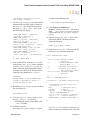
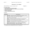
Setup
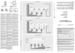
Figure 3 displays the basic setup for testing the
Serial-to-TCP and TCP-to-Serial communicator
application. The communicator application
emphasizes the on-chip peripherals such as UART
and MAC for the eZ80AcclaimPlus!™ MCU and
ZTP. This setup displays the connection diagram
between a PC, LAN/WAN, and the eZ80F91 Modular Development Kit (eZ80F910100KIT)
//shell_init(TTYDevID);
19. In the main.Mini.c file, add the following
code snippet above the return(OK); state-
AN021904–0808
Page 6 of 9
Data Transfer between Serial Link and TCP/IP Link Using eZ80F91 MCU
COM2
RS-232 Cable
P2
Ethernet/USB
COM1
Smart Cable
Interface Board
J5 ZDI
PC
Ethernet
eZ80F91 Mini
E-NET Module
eZ80F915005MODG
4 Port HUB
P1 Ethernet
Ethernet
LAN/WAN
Figure 3. Test Setup for Serial-to-TCP and TCP-to-Serial Communicator
Equipment Used
The hardware and software used in the Serial-toTCP and TCP-to-Serial communicator application
are listed below:
•
eZ80F91 Mini Ethernet Module
(eZ80F915005MODG) included in the
eZ80F91 Modular Development Kit
(eZ80F910100KITG)
•
PC with an Internet Browser, and HyperTerminal application set to 57.6 Kbps Baud, 8-N-1,
with no flow control.
•
Zilog TCP/IP Software Suite version 2.1 (ZTP
v2.1)
•
Zilog Developer Studio II–IDE for
eZ80Acclaim!® v4.11 (ZDS II–IDE v4.11)
Results
obtained. Transmission of data from the HTML
page to the HyperTerminal application is successful, thereby demonstrating the TCP-to-Serial data
transfer mechanism. Similarly, the transmission of
data from the HyperTerminal application to the
HTML page is successful, thereby demonstrating
the Serial-to-TCP data transfer mechanism.
Summary
This application note discusses the functionality of
the eZ80F91 MCU as an efficient embedded
Serial-to-TCP and TCP-to-Serial communicator.
The communicator application described in this
document demonstrates both Serial-to-TCP and
TCP-to-Serial communication. The eZ80F91
MCU as a Serial-to-TCP and TCP-to-Serial
communicator facilitates the transfer of information from the Internet to a serial device located
anywhere and vice versa.
The Serial-to-TCP and TCP-to-Serial communicator application is tested and expected results are
AN021904–0808
Page 7 of 9
Data Transfer between Serial Link and TCP/IP Link Using eZ80F91 MCU
References
The documents associated with the eZ80F91 family of microcontrollers, eZ80®, and ZDS II available on www.zilog.com are provided below:
•
eZ80® CPU User Manual (UM0077)
•
eZ80F91 Mini Enet Module Product
Specification (PS0236)
•
eZ80F91 Modular Development Kit
User Manual (UM0170)
•
eZ80F91 Modular Development Kit
Quick Start Guide (QS0046)
•
Zilog TCP/IP Stack API Reference
Manual (RM0040)Zilog TCP/IP Stack API
•
Zilog TCP/IP Software Suite
Programmers Guide (RM0041)
•
Zilog TCP/IP Software Suite
Quick Start Guide (QS0049)
•
Zilog Developer Studio II —
eZ80Acclaim!® User Manual (UM0144)
AN021904–0808
Page 8 of 9
Data Transfer between Serial Link and TCP/IP Link Using eZ80F91 MCU
Warning: DO NOT USE IN LIFE SUPPORT
LIFE SUPPORT POLICY
ZILOG'S PRODUCTS ARE NOT AUTHORIZED FOR USE AS CRITICAL COMPONENTS IN LIFE
SUPPORT DEVICES OR SYSTEMS WITHOUT THE EXPRESS PRIOR WRITTEN APPROVAL OF
THE PRESIDENT AND GENERAL COUNSEL OF ZILOG CORPORATION.
As used herein
Life support devices or systems are devices which (a) are intended for surgical implant into the body, or (b)
support or sustain life and whose failure to perform when properly used in accordance with instructions for
use provided in the labeling can be reasonably expected to result in a significant injury to the user. A
critical component is any component in a life support device or system whose failure to perform can be
reasonably expected to cause the failure of the life support device or system or to affect its safety or
effectiveness.
Document Disclaimer
©2008 by Zilog, Inc. All rights reserved. Information in this publication concerning the devices,
applications, or technology described is intended to suggest possible uses and may be superseded. ZILOG,
INC. DOES NOT ASSUME LIABILITY FOR OR PROVIDE A REPRESENTATION OF ACCURACY
OF THE INFORMATION, DEVICES, OR TECHNOLOGY DESCRIBED IN THIS DOCUMENT.
Z I L O G A L S O D O E S N O T A S S U M E L I A B I L I T Y F O R I N T E L L E C T U A L P R O P E RT Y
INFRINGEMENT RELATED IN ANY MANNER TO USE OF INFORMATION, DEVICES, OR
TECHNOLOGY DESCRIBED HEREIN OR OTHERWISE. The information contained within this
document has been verified according to the general principles of electrical and mechanical engineering.
eZ80AcclaimPlus! is a trademark of Zilog, Inc. eZ80Acclaim! and eZ80 are registered trademarks of
Zilog, Inc. All other product or service names are the property of their respective owners.
AN021904–0808
Page 9 of 9