1
Collect
™
Data Acquisition & Integration Control Software
User Manual
Connect and control - RS232,
RS422 - RS485 - TCP/IP Ethernet communications...
...directly with existing
spreadsheets, databases, files or
any program in Windows®
Collect 6.1 User Manual
Copyright Labtronics Inc. 2008
Printed in Canada.
Windows ® is a trademark of Microsoft® Corporation.
Publication History
FIRST EDITION January 2008
Customer Support:
Phone: (519) 767-1061
Fax: (519) 836-4431
E-mail: [email protected]
License and Warranty Agreement
Carefully read the following license and warranty information.
Copyright
Collect and this manual are copyright protected by Labtronics Inc. with all
rights reserved. No part of this software or manual may be copied, in whole
or in part without written consent from Labtronics Inc. except to make a
backup copy for normal use.
Windows® is a registered trademark of Microsoft® Corporation.
EULA (End User License Agreement)
Labtronics Inc. grants you a non-exclusive license to use Collect from a
single machine with each license purchased and to copy it for a backup in
support of your use of the program.
The Collect software (‘Software’) is defined as the Collect installed
program and all its system files And, Or any utility or service program or tool
included with the Collect Installation media. The ‘Software’ is licensed for use
On single machine installation.
Each machine, including thin clients, that will run the ‘Software’ represents a
single license of the ‘Software’.
Single machine installation definition: A single machine installation is
defined as any computer or electronic device that has the ‘Software’ installed
locally or is used to access the ‘Software’ through a remote terminal client.
Warranty
Labtronics Inc. warrants this product against defects in material and
workmanship for a period of 90 days from the original date of purchase. In
the event that this product shall prove defective in workmanship or materials,
your sole remedy shall be the replacement of this product.
The above is the only warranty of any kind, expressed or implied, including
but not limited to the implied warranties of merchantability and fitness for a
particular purpose that is made by Labtronics Inc. on this product.
Under no circumstances shall Labtronics Inc. nor its agents be liable for any
loss or damage, direct or indirect, incidental or consequential, arising out of
the use of, or inability to use, this product, nor shall Labtronics Inc. be liable
for costs incurred through third party claims of infringement of any copyright,
patent trademark or other intellectual property rights unless Labtronics Inc. is
found guilty of such acts.
Changes may periodically be made to the information herein. These changes
will be incorporated in new editions of this publication. The information
furnished herein is believed to be accurate and reliable. However, no
responsibility is assumed by Labtronics Inc. for its use.
Contents
Chapter 1 ................................................................ 1
Introduction .............................................................................. 1
The Collect Software .............................................................. 1
Collect SL ......................................................................... 2
Technical Support .............................................................. 3
The Collect User Manual ........................................................ 3
Terminology ....................................................................... 3
Conventions of the Manual ................................................ 4
General Procedures ............................................................... 5
The OK and Cancel Buttons .............................................. 5
Deletion Confirmation ........................................................ 5
On-Line Help ..................................................................... 5
Exiting from Collect ........................................................... 6
Changing the Preferences ................................................. 6
Last Minute Changes ........................................................ 6
Installation .............................................................................. 7
Contents of the Collect Package ....................................... 7
Hardware Requirements .................................................... 7
Software Requirements ..................................................... 7
Options for Configuring the Hardware and Software ........... 7
Installing the Collect Software ........................................... 9
COLLECT - Contents
i
Installing the ‘Remote RS232-to-TCP/IP Service’ Software 9
Registering the Software ................................................... 10
Chapter 2 ................................................................ 13
Quick Start-Just the Basics ..................................................... 13
Terminology Review ................................................................ 14
Changing Method Connections’ Port Settings ......................... 15
Quick-Start – Creating a Basic Method ................................... 15
The Demonstration Methods ................................................... 19
The Method Setup .................................................................. 19
The Template Setup .......................................................... 21
The Instrument Setup ........................................................ 21
RS232 Setup ..................................................................... 23
The Operation Setup ......................................................... 25
Running a Method .................................................................. 29
Opening a New Workbook ................................................. 29
Sending Commands .......................................................... 30
Place Data ........................................................................ 31
Closing the Method ........................................................... 32
Chapter 3 ................................................................ 33
Configure Your Own Method .................................................. 33
Defining the Preferences ......................................................... 34
Copy Method .......................................................................... 35
Defining a New Method ........................................................... 35
Specifying a Method Name ................................................ 36
Specifying the Interface Type ............................................. 37
Defining an Excel® Destination ......................................... 37
Selecting a Sheet Destination ........................................... 39
Defining a File Destination ................................................. 39
Defining a Wedge Destination ........................................... 39
Advanced Control .............................................................. 41
Setting up an Instrument ........................................................ 42
Specifying an Instrument Description ................................. 43
Selecting an Instrument Type and Name ........................... 43
ii
COLLECT - Contents
Defining the Instrument Number Format ............................ 43
Specifying the COM Port Information ................................. 44
RS232 Collector ................................................................ 44
Protocol ............................................................................ 49
Data Filter ......................................................................... 50
Discard Data ..................................................................... 51
Opening the COM Port ...................................................... 52
Adjusting Operation Checkboxes ...................................... 53
Timed Interval Data Collection ........................................... 54
Operation Hotkey .............................................................. 54
Reporting Result Data ....................................................... 55
Adding Time, Date, Counter, or User Macros ..................... 58
Saving the Instrument Setup ............................................. 58
Testing the Instrument Setup ............................................. 59
Saving the Method Setup .................................................. 59
Post to Labtronics ............................................................. 60
Importing/Exporting ................................................................ 61
Exporting a Method ........................................................... 61
Importing a Method ........................................................... 62
Exporting an Instrument .................................................... 64
Importing an Instrument ..................................................... 65
Importing a User Base Library Instrument .......................... 65
Chapter 4 ................................................................ 67
Running a Method ................................................................... 67
Opening a Method .................................................................. 67
Opening an Existing Destination ............................................ 67
Opening another Destination .................................................. 68
Excel® Interface - Sending Commands .................................. 69
Using One Instrument ....................................................... 69
Using Multiple Instruments ................................................ 70
Place Data ........................................................................ 70
Turning off the Instrument ....................................................... 71
Saving the Workbook ........................................................ 72
File Interface - Sending Commands ........................................ 72
COLLECT - Contents
iii
Using One Instrument ....................................................... 72
Using Multiple Instruments ................................................ 72
Monitor View ..................................................................... 73
Closing the Method ........................................................... 74
Wedge Interface – Sending Commands .................................. 75
Using One Instrument ....................................................... 75
Using Multiple Instruments ................................................ 75
Closing the Method ........................................................... 76
Hotkey – Sending Commands ................................................ 76
Chapter 5 ................................................................ 77
Configuring a New Instrument ................................................ 77
Introduction ............................................................................ 77
Importing a Device File ........................................................... 78
Instrument Manager ............................................................... 79
Adding a New Instrument ....................................................... 81
Communicating with the Instrument .................................. 83
RS232 Collector Setup ...................................................... 85
RS232-TCP/IP Collector Setup .......................................... 89
TCP/IP Collector Setup ..................................................... 91
Connecting the TCP/IP Collector to an E-Box ................... 92
Protocol ............................................................................ 92
Operation Setup ..................................................................... 94
Command ......................................................................... 95
Response .......................................................................... 95
Test Operation ........................................................................ 97
Macro Setup .......................................................................... 99
Test Macro ............................................................................. 101
Chapter 6 ................................................................ 103
The Simple Parser ................................................................... 103
Parser Types .......................................................................... 104
Parser Syntax ................................................................... 104
The Parser Selector ......................................................... 104
The Parser Orientation ...................................................... 105
iv
COLLECT - Contents
The Parser New Line ......................................................... 105
Designing a Simple Parser ..................................................... 106
Using the Numbers Parser Type ........................................ 106
Using the Position Parser Type ......................................... 107
Using the Delimiter Parser Type ........................................ 109
Advance Options for the Simple Parser .................................. 112
Affecting the Data Block .................................................... 112
Chapter 7 ................................................................ 115
Advanced Control – Sax Basic® Editor ................................. 115
Summary ............................................................................... 115
Function Type ......................................................................... 115
Accessing the Advanced Control function Setup ..................... 116
Allowing Script Debugging ................................................. 116
Using the Template Script File ................................................ 117
Template Script File ............................................................... 118
ActiveX Automation Members ................................................. 120
InterCollect Library.......................................................................................120
Affecting a Method’s Instrument Interfaces and Data .............. 122
Appendix A ............................................................. 125
ASCII Numbers ......................................................................... 125
Appendix B ............................................................ 131
Troubleshooting ....................................................................... 131
Appendix C ............................................................ 133
RS232 Cable Specifications .................................................... 133
Instrument / Device Cable Requirements ................................ 133
Standard RS232 Pin Configurations (DTE Relative) ............ 134
RS232 DB25 to DB9 pin converter ..................................... 135
RS232 null modem cables ................................................ 135
RS232 Cable Length ......................................................... 135
Index.................................................................................137
COLLECT - Contents
v
vi
COLLECT - Contents
Chapter 1
Introduction
The Collect Software
Collect is ideal for laboratories, field work, plant monitoring and
production environments where an easy-to-use yet extremely
powerful data acquisition and control system is required to automate
existing instrumentation, devices and the application procedures
they’re used with.
Collect is used around the World by thousands of companies in
almost every industry and discipline that performs testing and
analyses with digital instruments or devices such as balances, scales,
pH, ISE, EC, DO meters, spectrophotometers, force gauges, calipers
and micrometers, POC vital sign monitors, POS cash registers, PBX
phone systems, hardness testers, scanners, refractometers, density
meters, plate readers, thermometers, hygrometers, barometers,
shakers, stirrers and many more.
Collect is designed provide quick and accurate collecting, data
processing and reporting functionality from instruments or devices
with an RS232 serial communications port or Ethernet device
servers via TCP/IP and supports both high-speed asynchronous
data acquisition as well as bi-directional synchronous
communications. From simple data interfacing to automating
procedures that include multiple instruments and User controls,
Collect includes the tools to automate and enhance these
applications.
Collect provides you with hundreds of different instrument and
COLLECT - Introduction
1
The Collect Software
device configurations pre-set within its interface driver library and
provides access to Labtronics on-line User Base library of interface
drivers.
By simply adding these instrument interfaces to a
processing procedure (‘Method’) and contributing communication
parameters, you are able to collect data directly to Excel®, Files or
emulate the keyboard wedge (‘Wedge’) to transfer data to any open
Window® application without having to program operations.
Collect also offers independence as well as simplicity. If the
instruments or devices in the current database are not compatible or
available for your particular collecting process, visit Labtronics User
Base Library on-line or see ‘Configuring a New Instrument’ in
order to reconfigure the Operation Setup and define new
instruments. These are called user-defined instruments. You are able
to modify all the settings of these instruments in order to gain
maximum flexibility.
Collect is able to connect and control multiple instruments or
devices at one time and supports Windows® COM port numbers
COM1 through COM255. Standard RS232 COM ports can be
located on the motherboard or on an add-on board. The software is
also capable of connecting devices over a network via TCP/IP
communications. The software will work with multi-port boards
configured to work under your operating system. Collect is a
multitasking system that enables you to run many Methods as well
as allows you to work simultaneously with other applications,
including separate Excel® worksheets.
Collect works by extracting (parsing) only the data required from
any Instrument or Device and reports the parsed data directly to
Excel®, disk files or to directly to the cursor location in any open
Window. Collect also offers many additional preprogrammed
automation capabilities to meet a broad array of different interfacing
scenarios. Features such as auto-starting Methods, controlling
interface commands on a timed basis, Date and Time stamping, and
incorporating advanced control VBA script macros within an
interface Method for customized functionality.
Collect SL
Collect SL is a scaled down version of the Collect software that
has some of the more advanced interfacing automation capabilities
disabled. Collect SL is intended for users that only require a
simple ‘Wedge’ interface to transfer data to the cursor location in
2
COLLECT - Introduction
The Collect User Manual
any open Window® application. This manual will reference all
features of the Collect software. The following features of Collect
are disabled in the SL version are noted here only; ‘File |
Preferences’ to change the active method directory, ‘File | Open’,
‘Excel’ and ‘File’ interface types, ‘Auto-Start Method’ setting,
‘Advanced Control’ SAX Basic script editor, ‘Timed Collection’
Operation Setting processor, ‘Autostart’ Operation setting, Hotkey
operation setting, and Minimize to tray options
Technical Support
Should you require any assistance to set up your new interfaces or
automation routines please contact us for technical support or our
professional services available to deliver a turn-key systems.
Labtronics Technical Support
Phone: 519-767-1061 or E-mail: [email protected]
The Collect User Manual
It is assumed that you understand the general Windows® operating
system as well as the specific use and operation of Excel®. This
manual is intended for both Collect and Collect SL users and is
currently available in the English language only.
Terminology
A Method is a complete set of instructions for a particular type of
interfacing procedure. It defines all the instruments or devices that
are to be interfaced with at run-time within the same Method, their
operation commands and operation settings such as timed data
collection, the Excel® worksheet template, File destination or Wedge
destination, and the COM port settings. The starting cell
destination for the first data received from each instrument or device
if sending directly to Excel®, a file delimiter when sending directly
to a File, or cursor movements if sending to the ‘Wedge’ are also
defined within the Method’s instrument interface setup. A Method
is applied to a workbook or destination prior to collecting data.
An Instrument refers to any external device other than the
computer. It retrieves data and places it at a specific location on the
worksheet, to a file or cursor location. It is assumed that you know
COLLECT - Introduction
3
The Collect User Manual
the theory and principles of the instruments or devices being used and
their resultant data. Note that the terms Device and Instrument are
used interchangeably within the Instrument Manager (see
‘Configuring a New Instrument’, Chapter 5). The Device Library
however, refers to a Labtronics instrument database.
Operations allow the user to interact with the instrument or device.
The operation sends a Command String to the instrument in order to
prompt the instrument for a suitable response. A blank Command
String within an operation is typically used to receive data without
sending a prompt to the instrument. The operation retrieves the
response in order to organize the data before reporting to the
destination specified in the Method.
Conventions of the Manual
The following conventions are used throughout the manual:
4
•
The word 'press' refers to a keyboard response, where a specific
key or multiple keys are required to be pressed.
•
The word 'type' refers to a keyboard response, where a name,
description or directory is required.
•
The word 'click' refers to a mouse response.
•
Dialog buttons are referenced in ‘Bold Italic’ print.
•
Menu selections are referenced in bold print, with the hot key
character underlined (Alt key + underlined letter). For example,
when selecting from the menu, the manual will instruct you to
"Pull down the File menu and select Open". To do this you
would click on the File menu option, and then select the Open
option from the sub-menu, which appears when you select File.
•
Proper names used in the program are denoted by a leading capital
letter. For example: 'Instrument Manager' and 'Parser Setup'.
•
Dialog boxes are shown for your reference. The default values of
the program are stated, but examples are also included for
demonstration purposes. Therefore the dialog boxes being
described may not contain the exact same information as the
Figures.
•
Special keyboard keys such as Shift, Alt, Ctrl, ESCape, Tab,
COLLECT - Introduction
General Procedures
INSert, DELete, etc. will be enclosed in triangular brackets. For
example: <INSert> <DELete> <TAB> <SHIFT> <ALT>
<ENTER> etc.
•
Two keys in a row without a space such as <CTRL><INSert>
means press and hold down the <CTRL> key while pressing
the <INSert> key.
•
Computer input such as file names are specified within double
quotes in the manual. Do not include the quotation marks when
entering the input. For example, if "a:\setup" were included in
the manual to explain how to enter a file name, you would not
enter the quotation marks.
General Procedures
The OK and Cancel Buttons
Many of the dialog boxes used in the program contain both an ‘OK’
button and a ‘Cancel’ button. Selecting the ‘OK’ button will accept
any input you provided in the dialog box and then close the box.
Selecting the ‘Cancel’ button will also close the dialog box but
instead, ignore any input you provided.
Deletion Confirmation
Many of the setup dialog boxes used in the program contain a
‘Delete’ button. Selecting an item and then clicking on the ‘Delete’
button will cause a [Confirmation] dialog box to appear. Click on the
‘Yes’ button to confirm the delete command or click on the ‘No’
button to ignore the delete command.
On-Line Help
The On-Line Help is a Windows® Help file that allows you to
choose subjects relevant to the program available in English only.
When you choose Help from the menu bar, the Help window will
open on the screen. To further help simplify software
configuration, most setup windows throughout the program include
COLLECT - Introduction
5
General Procedures
‘Help’ buttons that go to the specific area of the Help file relevant to
that part of the program.
Exiting from Collect
To exit Collect, pull down the File menu and select Exit.
Changing the Preferences
In order to change the location of the Collect data directory:
1.
2.
3.
4.
Pull down the File menu and select Preferences.
A [Preferences] dialog box will appear.
In the Data Directory Location text box, specify the destination
of the Collect data directory.
Click on the ‘OK’ button to change the location of the Collect
data directory to the selected destination.
To disregard the changes, click on the ‘Cancel’ button. Both will cause
the ‘main screen’ to return.
Last Minute Changes
From time to time, improvements are made to both the software and
the manual. The latest changes will be explained in a README file
that will be installed with the program. To view this information:
1.
Double-click on the 'README' question-mark icon that was
installed in the same Program Group as Collect.
2. The readme.hlp file will be displayed in a standard Windows®based on-line help format, allowing you to jump to various
topics.
3. To exit the README, simply pull down the File menu and
select Exit.
If such a file exists, you may review the README file at any
time, although it is a good idea to read it before installing the
program.
6
COLLECT - Introduction
Installation
Installation
Contents of the Collect Package
One Collect 6.1 Installation CD
One Collect 6.1User Manual
Hardware Requirements
•
•
•
•
•
•
•
•
•
A PC with a Pentium II 300 MHz or higher processor.
256 MB of RAM for the XP operating system.
512 MB of RAM for the Windows Vista operating system.
Available hard-disk space, typical installation: 15 MB
maximum.
CD-ROM drive or equivalent
VGA or higher resolution monitor; Super VGA recommended.
Microsoft® Mouse, Microsoft® IntelliMouse, or compatible
pointing device.
COM1 / COM2 etc. ports to support RS232 communications
(the minimum is one available COM port).
Network connectivity if using TCP/IP collectors.
Software Requirements
Collect requires your computer to have the following:
•
•
Windows XP® Professional SP2 or Windows Vista® Business
operating systems
Microsoft® Excel 2000®,Excel 2003® or Excel 2007® if using the
direct to Excel® interface option.
Check your disks to verify you have the correct versions of the
operating system and application.
Options for Configuring the Hardware and Software
RS232 serial connection – communication between the instrument
and Collect is achieved by connecting the RS232 communications
port (COM port) on your Collect computer directly to the
instruments RS232 port.
COLLECT - Introduction
7
Installation
Note: It is important to have the correct RS232 serial cable required for
the instrument that is being connected. Some instruments or devices
will not interface to a computer (host) through a standard (‘straightthrough’) serial cable. Refer to Appendix C for more details on RS232
communications.
Serial to TCP/IP device server converter box – connects to an
RS232 output with a TCP/IP network and is able to translate to and
from specific data packets of serial data.
Serial to Ethernet converter box – connects an RS232 instrument to
a network and creates a virtual COM port for the converter box on the
Collect computer. This interface works in the same manner as the
‘RS232 serial connection’ described above but is a COM port created
over the network instead of locally on the computer itself.
Remote RS232 TCP/IP Collector Software – with the aid of a
Collector module included as part of the Collect package, it is capable
of gathering information from an instrument connected to the serial
port of a remote PC. The Remote RS232 TCP/IP Collector module
must be installed on the PC that the instrument is connected to. As
part of the Collect Instrument Manager, an RS232-TCP/IP Collector is
built in. Once activated, the collector connects to the Remote RS232TCP/IP Collector software, which opens the COM port. The Collect
Application is now capable of sending data to and receiving data from
the remote serial port via the TCP/IP connection.
USB Connection – Most USB interfaces require a software driver to
work with the hardware. If the instrument or device has a USB
interface and comes with a software driver that creates a standard
Windows™ COM port for the connection, Collect will work with this
interface in the same manner as if it were a standard RS232 serial
connection. In this case however, no special cable is required.
Wireless Connection – Various hardware options are available to
convert an instruments RS232 output to communicate with the Collect
computer in a wireless fashion. For example, Bluetooth converters
can create a wireless cable between the RS232 port of the device and
the COM port of the computer. Serial-to-Ethernet converters can be
used to connect the RS232 port of the device to a wireless access point
or wireless router.
Contact Labtronics for more details on the hardware and software
configuration options available to meet your specific
requirements.
8
COLLECT - Introduction
Installation
Installing the Collect Software
Collect comes with an automated setup program and can be
installed in English, French, German, Spanish, Italian or Japanese.
The setup program must be run from within, Windows XP® or
Windows Vista®.
1.
First have your Windows® operating system running and log on
as a user with Windows® Administrator rights.
2.
Insert the Collect CD into the CD ROM drive of your
computer.
3.
The install CD is configured to auto-start the setup routine. If
the setup does not begin automatically, you can manually start
it by double-clicking on the "setup.exe" file in the root
directory of the CD.
4.
Click on the language preferred in the Collect Installation
Menu.
5.
The setup program will establish the location of the data
directory. All Collect configuration files will be stored here;
Methods will be located in a sub directory below the data
directory using the Method Description as its directory name
and workbooks will be stored in the Method directory as a
default. If you wish to change the default location for the data
directory, simply enter the appropriate information here. The
setup program will create the necessary directories and copy
the files over.
6.
Double-click on the Collect icon on the Windows® Desktop
to start the program. You will see the main window for
Collect.
Installing the ‘Remote RS232-to-TCP/IP Service’ Software
Note: this software utility does not need to be installed on the same
computer as the Collect software. The Remote RS232-TCP/IP
Collector program allows RS232 devices to be connected to a
computer COM port and converted to a TCP/IP server port that can
then be connected to a Collect software installation located
elsewhere on the same network.
COLLECT - Introduction
9
Installation
1.
Follow the same steps 1 to 3 detailed in ‘Installing the Software’
above on the remote computer or laptop that will be connected
with the instrument or device.
2.
Click on the ‘Remote RS232-to-TCP/IP Service’ to install.
Registering the Software
Each new installation of the software requires its own registration.
You may install Collect from the original master disks or from copies
of these master disks. Once installed, the program is fully functional
for 30 days and will run as a single ‘Trial’ instrument license;
registration of the installation with Labtronics Inc. is required for
further use and/or in order to increase the number of instrument
licenses available to this installation. The initial registration must
be done within 30 days of installing the program.
When you first start Collect you will notice a 'Register Collect’
message indicating that this installation is either a trial version of the
product or needs to be registered.
To use the program within the first 30 days, simply click the
‘Cancel’ button and you will be taken to a fully functional program.
! Important: The Collect Activation key must be entered by a user
with Windows® Administrator rights. On Windows Vista®, the
Collect application must also be opened using the ‘Run as
Administrator’ feature of Vista® in order to run the application under
the Administrator account. To do this, right-click on the Collect icon
and select ‘Run as administrator’.
Activation Key
Contact Labtronics Inc. to obtain the Activation Key for this
installation quoting the 12 digit ‘CD Key’ located on the CD label and
the 16 digit ‘Registration Code’ displayed in [Register Collect]
dialog box which can be accessed through the main menu option
Register | Collect.
Your Activation Key can also be obtained on-line at: http://
www.labtronics.com/ActivateCollect.asp
The Activation Key for your Collect installation will be automatically
e-mailed to the e-mail address entered in this web page form.
10
COLLECT - Introduction
Installation
Figure 1.1: Register Collect window
Before registering the product, please ensure that the installation of
this product does not exceed the current licensing agreement with
Labtronics Inc.
Should you require technical support, you will be required to
provide the serial number. This can be retrieved from the [About]
dialog box. Pull down the Help menu and select About and the Serial
Number of this installation will be displayed in the Title bar of the
[About] window if it has been Registered.
To re-register, change the number of licenses or convert from
Collect SL to the full Collect version while using the program,
select the Register menu option and select ‘Collect SL’ or
‘Collect’ depending on the version of the software or licenses
purchased. This will also cause the [Register Collect] or [Register
Collect SL] dialog box to appear.
COLLECT - Introduction
11
12
COLLECT - Introduction
Chapter 2
Quick Start-Just the Basics
The purpose of this chapter is to introduce you to the Collect
environment. This chapter will teach you the basic components of
Collect in order for you to begin collecting, processing and reporting
data as soon as possible. Comprehensive details of the Collect
software are provided in Chapters 3, 4, 5, 6 and 7 as well as several
Appendices for your reference.
! Before plugging an RS232 Serial cable from an instrument or device
into the computer COM port, verify the cable pin-out requirements
match those specified in the operating manual for that instrument or
device. Some instruments and devices do not support the standard
pin-out configuration and using an incorrect cable could damage the
instrument or device.
You should first be familiar with your Windows® operating
system, and you should know how to use the mouse to pull down
menus as well as select options. More importantly, the instrument or device should already be connected to a COM port on
the back of your computer or ethernet port with the proper cable
required for that connection, and you should be able to provide
the communication parameters specific to each instrument or
device.
If you have not yet installed Collect onto your computer, go back to
the Installation section now and follow the required steps. Once you
have installed Collect onto your computer, you are ready to start the
program. Start Collect from Windows® by double-clicking on the
Collect icon.
COLLECT - Quick Start - Just the Basics
13
Terminology Review
Upon entering the program you will see the Collect ‘main screen’
that lists the active Method list as shown in Figure 2.1.
Figure 2.1: Collect main screen
Terminology Review
A Method is a complete set of instructions for a particular type of
interfacing procedure. It defines the instruments, the Destination file
or application, the cell destination, delimiter or cursor movement
when data is received, and the COM port or TCP/IP settings. A
Method applies a set of interfaces and instructions prior to collecting
data.
For more advanced application automations, such as creating User
Prompt windows, or combining different instrument operations
together to name just a few, Collect includes a SAX Basic script
editor, which can apply VBA macros within a Method’s instrument
interfaces and automated control over their operation commands.
An Instrument refers to any external device other than the computer.
It retrieves data and places it at a specific location in the destination
defined. It is assumed that you know the theory and principles of the
laboratory instruments being used and their resultant data
14
COLLECT - Quick Start - Just the Basics
Changing Method Connections’ Port Settings
Operations allow the user to interact with the instrument. The
operation sends a Command String to the instrument in order to
prompt the instrument for a suitable response. The operation
retrieves the response in order to organize the data.
Changing Method Connections’ Port Settings
The Port Setup for an Instrument/Device interface contained within
existing Methods can be changed through the ‘Edit | Method Connections’ menu option instead of accessing the full [Method Setup].
Click once on the Method Name that requires Port Setup changes the
main menu option ‘Edit | Method Connections’ or right-mouse button
click to open the [Method Connections] dialog. Select the Instrument/
Device name from the list then ‘Edit’ button to change either its
Collector type or ‘Setup’ the communication port for the Collector.
Refer to Chapter 5 for details on the ‘RS232 Collector’, ‘RS232-toTCP Collector’ or ‘TCP/IP Collector’ Setup.
After completing the Collector Setup, click on the ‘OK’ button in the
[Method Connections] dialog to save the changes and return to the
main screen. The ‘Cancel’ button will close the [Method Connections] dialog without saving the changes.
Quick-Start – Creating a Basic Method
Follow these steps to create a basic interface Method. Comprehensive details on setting up Methods and Instruments with screenshots
of the setup process are defined in Chapters 3 through 7.
From the Collect ‘main screen’:
1.
Pull down the Edit menu and select New Method....
In the [Method Setup] dialog
2.
Give the Method a unique name in the ‘Method Name’ field
provided.
COLLECT - Quick Start - Just the Basics
15
Quick Start - Creating a Basic Method
3.
Select a ‘Wedge’, ‘File’ or ‘Excel’ interface type depending on
where the results need to be sent.
‘Wedge’ will send received data to active cursor location, ‘File’
sends a disk file (ASCII format) on the computer or network and
‘Excel’ creates a direct interface to Microsoft® Excel®.
4.
Select ‘Destination’ button, browse to the File or Application to
be connected with. Select that file or application and choose the
‘Open’ button. For a ‘Wedge’ interface, enter the Application
File used to open the Data Destination (e.g Excel.exe) then enter
the Data Destination (e.g. Workbook.xls). Note: To specify a
Web address simply enter the URL web address in the Data
Destination line instead of an actual file after specifying
‘IExplore.exe’ as the Application File.
5.
Click on the ‘Add’ button in the ‘Instruments/Devices’ list box
section to add the first instrument or device connection to this
Method.
On the [Connections] dialog
6.
Give the instrument a name in the ‘Description’ field provided.
7.
Using the pull-down menus, select the instrument/device ‘Type’
and ‘Name’ (if your instrument or device is not contained within
Labtronics Instrument Library, select the ‘Instrument Manager’
button and refer to Chapter 5 – Configuring a New Instrument,
before proceeding further)
8.
Define the communication parameters through the ‘Port Setup’
button. For RS232 communications, select the ‘RS232 Collector’
and then the ‘Setup’ button if connecting to a Windows® COM
port. The settings defined here must exactly match the port
settings of the instrument’s RS232 port, which are usually
defined within the instrument’s operating manual or can be
displayed through a menu option of the instrument.
Selecting the ‘Test’ button in the [RS232 Collector] dialog can test
the communications with the instrument or device.
The ‘TCP/IP Collector’ and ‘RS232 to TCP/IP Collector’ are
described in Chapter 5.
16
COLLECT - Quick Start - Just the Basics
Quick Start - Creating a Basic Methodd
9.
Each Operation that is loaded after selecting the instrument
‘Type’ and ‘Name’ will default to an Operation Setting that uses
Collect’s ‘Asynchronous’ processor. Refer to Chapter 3 –
Configure Your Own Method, Operation Settings section for
details on changing this to a ‘Timed Collection’ processor if
required.
10. Once the Operation Settings are defined, the ‘Results’ section for
each Operation that returns data will need to be filled out.
Define either the ‘Starting Cell’, ‘Delimiter’ or ‘Cursor Movement’ displayed in the ‘Results’ section for each Operation that
has a ‘Result Name’ that is to be reported. First select the
Operation in the ‘pull-down’ menu of the Operation Setup
section and then define the ‘Starting Cell’, ‘Delimiter’ or ‘Cursor
Movement’ to the right of each named value down the ‘Result
Name’ column.
Excel® Interface Type
Starting Cell format for a ‘Result Name’ example: “=B3” or
“=Sheet1!B3” (without quotations). Will send the first value
received to ‘B3’ in the Excel® sheet and then move down the ‘B’
column after each reading is received. (Note that this interface
type makes a direct connection with the Excel® COM object is
not affected by use of the keyboard or mouse during run-time
data collection)
File Interface Type
Delimiter format for the ‘Result Name’ values can be any
character or combination of characters. Example:
“tilda+pipe+tilda” would be entered as: “~|~“ (without
quotations) in the Delimiter column to the right of the ‘Result
Name’. The Delimiter entered will be placed between this value
and the next value in the ‘Result Name’ list at run-time. Use the
arrows on the right side to change the order of the data that will
be reported.
Results Setup Example:
Result Name
InstrumentData
[Time]
StaticText
COLLECT - Quick Start - Just the Basics
Delimiter
~|~
~|~
17
Quick Start - Creating a Basic Method
At Run-time an instrument reading of 15.234 is received and will
be written to the defined ‘Destination’ file as;
15.234~|~12:35:52~|~StaticText
Wedge Interface Type
Cursor Movement format for a ‘Result Name’ are defined by
writing out the desired movement required after each result is
reported between “<” and “>” symbols. Keystrokes may also
be combined within the same ‘Cursor Movement’ cell.
Cursor Movement keystrokes supported by Collect:
<Enter> , <Tab> , <Down> , <Up> , <Home> , <End> ,
<Right> , <Left>
Result Name
InstrumentData
[Time]
StaticText
Cursor Movement
<Tab>
<Right>
<Enter><Home>
At run-time, the instrument reading is sent to wherever the
cursor is located. Collect then ‘Tab’s to the next field and enters
the ‘Time’ stamp, moves right and enters the ‘StaticText’.
Collect then automatically executes an <Enter> and <Home>
keystroke combination.
11. After defining the instrument Connection to the Destination,
select the ‘OK’ button
On the [Method Setup] dialog
12. To add another instrument or device connection to this Method,
select the ‘Add’ button and repeat steps 6-11 above, otherwise,
select the ‘OK’ or ‘Finish’ button to Save and Exit from the
Method Setup and return to the Collect main screen.
On the Collect main screen
Double-click on the new Method name that was just created or select
it and choose the menu options ‘File | Open New…’ to start this
Method.
18
COLLECT - Quick Start - Just the Basics
The Demonstration Methods
The Demonstration Methods
In order to become familiar with the collecting process, Labtronics has
supplied a number of Demonstration Methods that use Excel® as the
destination for result data.
Use the demonstration Method to help you become familiar with the
basic Collect components or modify and incorporate directly into
your daily operations.
The Method Setup
Modifying one of the Demonstration Methods.
Note: All Demonstration Methods are setup to use Microsoft® Excel®
file templates and Collect’s direct to ‘Excel’ object interface. If
Microsoft® Excel® is not available on your computer the demonstration Methods will need to be modified to use a Wedge or File interface
type and the Operation Results re-defined to use a ‘Delimiter’ if
sending to a ‘File’ or ‘Cursor Movement’ if connecting via the ‘Wedge’
interface type instead of the ‘Starting Cell’ that is defined within the
demonstration methods.
From the Collect ‘main screen’:
1.
2.
3.
Click on a demonstration Method of interest to select this as the
one to be modified.
Pull down the Edit menu and select Method.
A [Method Setup] dialog box similar to the example in Figure 2.2
will appear.
COLLECT - Quick Start - Just the Basics
19
The Method Setup
Figure 2.2: Method Setup, Start Setup Tab.
The [Method Setup] dialog box is where the details of the collecting
and automation processes are specified. The setup process begins on
the [Method Setup] dialog.
The ‘Wedge’, ‘File’ or ‘Excel’ interface types for the instrument
data is global to the Method. One cannot specify a Wedge interface
for one instrument and directly to Excel® type for another instrument
within the same Method. If different destinations were required
within the same Method, this would need to be set up in the
‘Advanced Control’ SAX Basic script editor or define separate
Methods for the different destinations.
If you do not have Excel® installed on your computer, select either
the ‘Wedge’ or ‘File’ interface options and define a new ‘Destination’
File or Windows® application for the interface.
20
COLLECT - Quick Start - Just the Basics
The Method Setup
The ‘Auto-Start’ check box will automatically launch this Method
upon opening Collect. Toggle this on with a check mark to apply the
‘Auto-Start’ to this Method. The Excel® interface template or
‘Wedge’ destination file or application will be automatically opened as
well upon this Method starting.
‘Advanced Control’ is a SAX Basic script editor that allows for VBA
scripts to be embedded as a program layer global to the entire Method
for full automation control over the instrument interfaces and their
operations. The ‘Advanced Control’ feature is an optional tool used
for adding a variety of new functions and capabilities to the core
Collect program and is detailed in Chapter 7.
The Template Setup
If using the Excel® interface option, click on the ‘Template Setup’
button. This will automatically open Excel® and the default template
file, “MethodTemplate.xls” set for this Method. The default
template of the demonstration Method may contain static text,
formulas, macros and graphs. Each time a new worksheet is run for a
Method, the template spreadsheet will be opened to acquire any data
gathered.
The Instrument Setup
The Instruments/Devices list box displays the instruments that are
connected by the Method. The [Connections] dialog can be accessed
through the Instruments/Devices list box.
1.
2.
Click on the first Description name in the Instruments/Devices
list box. Then click on the ‘Edit’ or ‘Next’ button.
A [Connections] dialog similar to the example in Figure 2.3 will
appear and the settings for that instrument or device connection
are displayed.
COLLECT - Quick Start - Just the Basics
21
The Method Setup
Figure 2.3: Connections Tab
The [Connections] dialog is where the COM port or TCP/IP port
and operation information is specified for the instrument interface.
If you have your instrument connected, you can adjust the
‘Instrument / Device Selection’ using the pull down menu’s to
match the Instrument /Device ‘Type’ and manufacturer and model
’Name’ if it is available in Collect’s Instrument Library.
If you do not have an instrument that is available in the Instrument
Library, proceed with the demonstration Method; however, you
will not be able to gather data. Refer to Chapter 5 for details on
configuring a New Instrument using Collect’s Instrument Manager.
To specify the COM Port Information of the instrument or device,
click on the ‘Port Setup’ button. A [Communications Setup] dialog
box similar to the example shown in Figure 2.4 will appear allowing
you select the RS232 Collector, TCP/IP Collector, or RS232-to-
22
COLLECT - Quick Start - Just the Basics
The Method Setup
TCP/IP Collector. After selecting the appropriate Collector type you
can adjust the communication parameters to match your instrument
settings by clicking on the ‘Setup’ button.
Figure 2.4: Communications Setup
RS232 Setup
Simply change the parameters listed in Figure 2.5, [RS232 Collector]
window, to match those of your instrument or device which can
typically be found in the operating manual or by entering the digital
menu display of the instrument and browsing though its settings.
Figure 2.5: RS232 Collector
COLLECT - Quick Start - Just the Basics
23
The Method Setup
A filter can also be applied to incoming data should any output from
the instrument need to be altered. The setup is accessed by clicking
on the ‘Filter’ tab displayed in the Collector Setup as shown in Figure
2.6.
Figure 2.6: RS232 Collector Filter Setup
Erroneous data output can be discarded completely and ignored by
the software by using the Discard Data Containing option. This will
search the complete string of data and if the text that was entered
through the ‘Add…’ button setup is found at run-time the software
will delete that data string and be ready for the next reading.
24
COLLECT - Quick Start - Just the Basics
The Method Setup
Figure 2.7: RS232 Collector: Discard Data Setup
‘TCP/IP Collector Setup’ and ‘RS232 to TCP/IP Collector Setup’ are
described in Chapter 5.
The Operation Setup
The Operation section of the [Connections] dialog is where the Run
Time details of the operations are specified. Once the Instrument/
Device Type and Name are selected, all of the instrument specific
settings in the Operation Setup section of the [Connections] dialog
are automatically filled with the settings contained in the Labtronics
Instrument Library.
For more information regarding the settings in the Operation
Setup, see ‘Adjusting the Operation Checkboxes’, Chapter 3.
In the Arguments section of the Operation Setup, the Parameter
Name and Value list box are disabled. If an argument needs to be
specified at run time (inserting a value from Excel® into the Command
String before sending it to the instrument or device), here is where the
cell location is defined. Also note, the Arguments option only works
with the ‘Excel’ interface option selected for a Method.
COLLECT - Quick Start - Just the Basics
25
The Method Setup
In the Results section of the Operation Setup the destination of the
collected data is indicated. If the Method interface uses the ‘Excel’
option, the ‘View Template’ button will be available in order to take
note of the desired data destinations. Select the ‘View Template’
button to open the template file then close the file. This will cause the
[Connections] dialog to return.
Beside the predefined Result Name is the Starting Cell list box is
where a relative or absolute cell is referenced. If you decide to use a
relative cell reference (e.g. =B3), Collect automatically addresses the
information in a columnar fashion, automatically adding data down
the column specified starting at the row specified. When collecting
data, Collect identifies the next empty cell in the Starting Cell column
and inputs the data accordingly. Collect can also send collected data
to different worksheets by specifying the Starting Cell to be equal to
the “sheet name”!“cell value” (e.g. =Sheet1!B3) or absolute cell
locations using the dollar sign ‘$’ symbol between the Column
address and Row address (example “=B$3”).
To add a Date or Time or Counter stamp to the values received
simply enter the name of stamp required in square brackets in the
first empty row in the Result Name column and set the Starting Cell
for each.
Example: In row 2 enter under the Result Name: [Time] and Starting
Cell: =D3.
The date macro is: [Date], the counter macro is: [Counter], Time with
milliseconds is [Time.ms], and milliseconds is [Milliseconds].
If the ‘Wedge’ or ‘File’ interface options were selected, the Operation
Results section displays either ‘Cursor Movement’ or ‘Delimiter’ for
the respective interface types. Supported ‘Cursor Movement’
keystroke formats and File types are further defined in Chapter 3.
26
COLLECT - Quick Start - Just the Basics
The Method Setup
Figure 2.8: Connections Tab
To specify automatic retrieval of readings based on a timed interval,
select the Operation in the pull-down menu that contains the
Command String for retrieving the instrument data. Next, select the
checkbox to the left side of the ‘Settings’ button directly below the
Operation selected in the Operation pull-down menu to toggle it on
and click on the ‘Settings’ button to display the [Operation Settings]
dialog box as shown in Figure 2.9.
COLLECT - Quick Start - Just the Basics
27
The Method Setup
Figure 2.9: Operation Settings
Select the ‘Timed Collection’ in the Processor pull-down menu then
click on the ‘Setup’ button to set the desired time interval. See Figure
2.10.
Figure 2.10: Continuous Reading Setup
Note that in some demonstration Methods, the same physical
instrument is defined within the Method multiple times. This
can be used in cases where one set of readings needs to be sent
to one column and another set of readings sent to a different
column. Also, take note that the ‘Start on Method Open’
setting is unchecked. This setting describes the state of the
communication port when the Method is opened. Since two
instruments cannot occupy the same COM port at the same
time, one of the ports must be opened manually after closing
the other when it is required.
Click on the ‘OK’ button to exit the [Connections] setup and return
to the [Method Setup] dialog shown in Figure 2.11. Click on the
‘OK’ button to Save and exit the Method Setup.
28
COLLECT - Quick Start - Just the Basics
Running a Method
Figure 2.11: Finish Setup Tab
Running a Method
Opening a New Workbook
In order to run a new workbook for the demonstration Method:
1.
2.
Click on the demonstration Method from the Collect ‘main
screen’ to select this as the Method to open.
Pull down the File menu and select Open New.
Or, Double-click on the Method Name in the main window Method
List.
This will automatically open Excel® default template file and attach
the Collect floating toolbar object directly the Excel® template (See
Figure 2.12).
COLLECT - Quick Start - Just the Basics
29
Rinning a Method
If the Method was altered to send to the ‘Wedge’, starting the
Method will automatically open the Wedge Destination file or
application that was defined within the Method Setup and the
floating toolbar will appear over the Collect main screen. The File
interface destination is not opened but a view of the data being
reported to the Destination File can be seen through the instruments
Monitor window.
Figure 2.12: Multiple Instrument Demo Worksheet Template prior to
collecting data
Sending Commands
Once the demonstration Method’s workbook is opened and the
instrument is turned on, you can begin to collect data. Predefined
operations determined from the Operation Setup are located as a sub
menu in the toolbar. This toolbar floats above the workbook, and the
Instrument Description is used as the toolbar button name (See Figure
2.13). By clicking on the arrow above the Instrument Description,
you can select the Start operation to open the communication port if
this did not auto-start with the ‘Start on Method Open’ instrument/
device setting. Now that the communication port is opened, you can
click on the tool button to view a list of the active operation
commands available. Click on the operation associated with collecting
30
COLLECT - Quick Start - Just the Basics
Running a Method
data to start this operation. Viewing the Operation List again, the
operation that was selected should now appear with a ‘Stop’ to the
left of the operation name indicating that this operation is running.
Selecting this again will stop the operation.
Most instrument or device operations in the Labtronics Instrument
Library contain the necessary Command String to retrieve data from
that instrument or device. Any Instrument Library Operation named
‘Unidirectional’ does not contain a Command String and is intended
to listen to the COM port for any incoming data if it is being
‘Printed’ or ‘Sent’ from the instrument or device to the computer by
some other means such as selecting a Print or Send key on the
instrument itself or using a foot-pedal to send the data.
Figure 2.13: Collect’s Excel® Workbook toolbar
Place Data
‘Place Data’ is a toolbar feature available to the ‘Excel’ interface
option of the Method. Instrument data can be sent to any Row
within in the Excel® workbook by using the Place Data feature but
data will continue to be placed in the same Column address defined
for that Operations Starting Cell. With Place Data turned ON and
clicking on a new Cell in a different Row, the next reading received by
Collect will be sent to that new Row location.
The Place Data feature can be started from the workbook toolbar by
clicking on the green triangle. See Figure 2.14.
COLLECT - Quick Start - Just the Basics
31
Running a Method
Figure 2.14: Place Data is OFF
When Place Data is active a red circle will be displayed. Clicking on
the red circle will “stop” the Place Data feature and readings will again
be entered down the column in sequential order.
Figure 2.15: Place Data is ON
Note: Place Data can remain turned ON; but, if any Cell in the
Workbook is selected and a reading from the instrument is sent, the
software will send the result to that new Row location.
Closing the Method
Once the collecting session is complete;
1.
2.
3.
4.
Click on the instrument tool bar button.
Then click on the Close operation to turn off the interface with
the instrument and automatically close the communication port.
Save the Excel® workbook, File or Application using its standard
save options available.
Exit Excel®, the Destination File or Application as usual.
This will cause the Collect ‘main screen’ to return.
For more information regarding any of these topics, see
‘Configuring your own Method’, Chapter 3 and ‘Running a
Method’, Chapter 4 as a reference.
32
COLLECT - Quick Start - Just the Basics
Chapter 3
Configure Your Own Method
If you have not yet installed Collect onto your computer, go back
to the Installation section now and follow the required steps. Once
you have installed Collect onto your computer, you are ready to
start the program.
Start Collect from Windows® by double-clicking on the Collect
icon.
Upon entering the program you will see the main Collect screen,
shown in Figure 3.1.
COLLECT - Configure Your Own Method
33
Defining the Preferences
Figure 3.1: Collect ‘main screen’
A Method is a complete set of instructions for a particular type of
test, analysis procedure or interfacing routine. In order to configure a
Method, you must define the instruments, the Destination and either
a Starting Cell destination, Delimiter or Cursor Movement for the
collected data of each Operation that receives results. The Method
also defines the COM port or TCP/IP settings for each instrument
and each connection must exactly match those of your instrument or
device settings.
Defining the Preferences
The active data directory for Collect’s list of Methods can be
modified after installation by selecting the menu option ‘File |
Preferences’. To change the directory, select the browse button ‘…’
to the right of ‘Data directory location’ and select a new folder path
in the ‘Browse for folder’ dialog. Selecting ‘OK’ will set this folder
as the new location for storing the Methods.
Show text on toolbar buttons – Will show the text associated with
the main screen toolbar button when checked.
34
COLLECT - Configure Your Own Method
Defining a New Method
Open minimized – Will automatically minimize the Collect main
screen when toggled on with a checkmark.
Minimize to tray – Will minimize the Collect main screen to the
taskbar tray icons when toggled on with a checkmark.
Copy Method
1.
2.
3.
4.
From the Collect main screen, select the Method to copy.
Pull down the Edit menu and select Copy Method to open the
Copy Method window.
Enter the new ‘Method Name’.
Click ‘OK’.
Defining a New Method
1.
2.
From the Collect ‘main screen’, pull down the Edit menu and
select New Method.
A [Method Setup] dialog window similar to the example shown
in Figure 3.2 will appear.
COLLECT - Configure Your Own Method
35
Defining a New Method
Figure 3.2: Method Setup
When creating a Method, you must complete the [Method Setup]
dialog window.
Specifying a Method Name
Type in the Method Name of the new Method in the field provided.
The name of the Method must be unique so that you will be able to
consistently identify each Method when using Collect.
The ‘Auto-Start Method’ option will automatically launch this
Method upon opening the Collect software. Click on the checkbox
to the left ‘Auto-Start Method’ to activate this feature.
The ‘Minimize toolbar to tray’ option will allow Collect’s ‘Wedge’
or ‘File’ toolbar to be minimized to Windows® taskbar tray icons.
If any Instrument in the Method has an Operation set to
‘Autostart’, the toolbar will automatically minimize to the taskbar
tray when that Method is launched.
36
COLLECT - Configure Your Own Method
Defining a New Method
Specifying the Interface Type
The type of interface dictates how Collect will add instrument data
to a defined Destination. Only one type may be chosen per Method
Setup. The type of interface to choose depends on where the
collected data needs to be sent to. For example, the ‘Excel’ option
would be the best one for connecting an instrument directly to
Excel®. The ‘File’ option would be best for connecting an
instrument to a file on the computer or local area network such as a
text file or .csv file. The ‘Wedge’ option can be used for transferring
data to the cursor location in any open window such as an Internet
Explorer® Web Client application or a database application’s entry
form.
‘Wedge’: Check to send instrument data automatically to the cursor
location in any open Windows® application by emulating the
keyboard.
‘File’: Check to send instrument data directly to a disk file located
anywhere on the computer or network.
‘Excel’: Check to send instrument data directly to Excel® without
requiring the use of the keyboard wedge.
Only the Excel® Destination will allow a user to define a Default
Sheet name or access the ‘Template Setup.
Defining an Excel® Destination
The Excel® interface type creates a direct connection between the
instruments and the Excel® workbook without using the cursor.
This allows users to continue working with the keyboard and mouse
in other applications without interfering with the incoming
instrument data. This interface type also allows Collect to connect
and control multiple instruments and operations at the same time.
With the ‘Excel’ option checked, select the ‘Template Setup’ button.
If no Excel® file was defined as the Destination, selecting the
‘Template Setup’ button will automatically open a blank Excel®
workbook. You can add static text, formulas and Macros to the
Excel® workbook. Saving the changes in Excel® before closing will
apply this as the Method’s new Excel® Template. Each time a new
worksheet is run for the Method, the original template spreadsheet
will be opened to acquire any data gathered.
COLLECT - Configure Your Own Method
37
Defining a New Method
In order not to destroy the template spreadsheet when saving a new
workbook, use the Save As command. The workbook name and
location is up to you.
Applying an Outside Excel® (.xls) workbook as the Method
Template.
In order to apply a previously configured Excel® workbook as the
default template in a Method:
1.
2.
3.
Click on the ‘Destination’ button.
The cursor will be flashing in the File Name text box. Type in
the name of the previously configured workbook or browse the
file system to locate the file. (See Figure 3.3) Click on the
configured workbook.
To automatically copy the selected template, click on the
‘Open’ button. Click on the ‘Cancel’ button to close the dialog
box without copying the template.
The copied template will be renamed "MethodTemplate.xls" and
placed in that Method’s directory as the default template.
Figure 3.3: Locate the template
38
COLLECT - Configure Your Own Method
Defining a New Method
Selecting a Sheet Destination
If the ‘Excel’ interface type is selected, click on the Default Sheet
text box. In order to specify the sheet destination for the collected
data, type in the sheet name. If the Default Sheet name is left blank,
note that the currently selected worksheet in the template will act as
the destination worksheet for all collected data unless the
Operations ‘Result Name’ Starting Cell is directed to different sheets
in the workbook.
Defining a File Destination
The ‘File’ interface will connect the instrument data and any other
user defined data to the file selected as the destination.
With the ‘File’ option checked, click on the ‘Destination’ button to
open the File Destination dialog box. Create a New File or browse
to a folder location select an existing file to append the instrument
data to. New Files can typically be added to a folder location by
browsing to that location, right clicking in the dialog box list window
and selecting ‘New | Text Document’.
Select ‘Open’ when finished.
File types supported: Any file format that supports ASCII text data
such as a Notepad *.txt or *.csv file.
Defining a Wedge Destination
With the ‘Wedge’ option checked, click on the ‘Destination’ button
to open the [Wedge Destination] dialog as shown in Figure 3.4.
Figure 3.4: Wedge Destination dialog
COLLECT - Configure Your Own Method
39
Defining a New Method
In the ‘Application File’ text box, type in the location and name of
Windows® application executable or select the ‘…’ browse button to
open the [Application File] dialog and search for the executable
(.EXE) file. Select the executable file required for the destination
data file and then click on the ‘Open’ button to return this file name
and location to the [Wedge Destination] window. Select the
‘Cancel’ button in [Application File] dialog to close without
applying a selection. This will return you to the [Wedge
Destination] dialog.
Next, define the ‘Data Destination’ if necessary, to be opened when
this Method is run. This must be a file type that is typically opened
by the defined Application file. For example, the Application file
"WinWord.exe" typically opens a Data File like "MSWord.doc".
In the ‘Data Destination’ text box, type in the location and name of
File or select the ‘…’ browse button to open the [Data Destination]
dialog and search for the file. Select the file required for the
destination data file and then click on the ‘Open’ button to return
this file name and location to the [Wedge Destination] window.
Select the ‘Cancel’ button in [Data Destination] dialog to close
without applying a selection. This will return you to the [Wedge
Destination] dialog.
Leaving the ‘Data Destination’ text box blank, Collect will launch
the .EXE as a new file.
Entering only a Windows Caption or partial Windows Caption
(typically the Window title bar name) in the Data Destination text
box will send data to that specific Window.
Leaving both undefined, Collect will send the data to whichever
Window has control of the active cursor location at run-time.
Connecting to Internet Explorer
From the [Wedge Destination] dialog box enter or browse to the
Internet Explorer® application file. This is typically found in the
root directory: \Program Files\Internet Explorer\IEXPLORE.EXE
Next, in the ‘Data Destination’ section, enter the complete web site
URL address to use in the Address line of Internet Explorer®. Do
40
COLLECT - Configure Your Own Method
Defining a New Method
not use the Browse ‘…’ button unless you want to connect to an
off-line page that was saved previously to a file.
The format for the URL address in the ‘Data Destination’ section
must include "http://" preceding the site address. For example,
http://www.labtronics.com/col.htm, would be the correct ‘Data
Destination’ format.
Advanced Control
The ‘Advanced Control’ option allows VBA macro scripts written
in the SAX Basic language to be incorporated as layer within a
Method enabling Collect to add virtually any function, feature or
procedure that is not inherent to the program. This option is
intended for users that have some VB or VBA programming
knowledge.
A script, if necessary or desired for enhanced automation, should be
created after the basic settings of the Method are completed. For
example, create and save the Method with the instrument interfaces
and operation settings needed first. The Method can be modified at
any time to add additional functionality through the ‘Advanced
Control’ option and depending on what functions or parameters are
being called by the script at run-time, their names and settings
would need to be known in order to create the script.
Select the check-box to the left of the ‘Advanced Control’ button to
activate this feature. Clicking on the ‘Advanced Control’ button
will open the [Advanced Control Setup] dialog box as shown in
Figure 3.5. Enter a name for the script then select the ‘Edit Script’
button to open the SAX Basic Editor to create or modify an existing
script. Save the script using the ‘Save’ options in the SAX Basic
Editor. Closing SAX Basic will return you to the [Advanced
Control Setup] dialog. To debug the script during a run-time
scenario, place break-points within the code then a check-mark
beside the ‘Allow run-time debugging’ option to toggle this on.
Figure 3.5: Advanced Control Setup
COLLECT - Configure Your Own Method
41
Setting up an Instrument
Click on the ‘OK’ button to apply the changes.
Contact Labtronics Collect support department for details on our
Professional services available to write custom application scripts if
help is required.
Collect’s SAX Basic Editor is detailed in Chapter 7 and the SAX
Basic Editor Help options.
Setting up an Instrument
1.
2.
Click on the ‘Add’ button from the [Method Setup] dialog.
A [Connections] dialog similar to the example in Figure 3.6
will appear.
Figure 3.6: Connections dialog
42
COLLECT - Configure Your Own Method
Setting up an Instrument
When adding an instrument to a Method, you must complete the
[Connections] dialog.
Specifying an Instrument Description
A cursor will be flashing in the Description text box. Type in a
description of the instrument to be added. The description of the
instrument must be unique so that you will be able to consistently
identify the instrument when using Collect. The Description name
entered here will be displayed as a button on the Collect floating
control toolbar at run-time.
Selecting an Instrument Type and Name
By clicking on the arrow to the right of the Type and Name text box
you can view a list of instrument types and names that are available
in the Labtronics Instrument Library. Select an instrument ‘Type’
by clicking on an item from the list. The instrument ‘Type’ is
required in order to retrieve a list of corresponding instrument
‘Name’s. Then select an item from the ‘Name’ list.
If the instrument you have is not found in the Name text box, go
directly to ‘Configure a New Instrument’, Chapter 5 or check
Collect’s User Base Library on-line at: http://www.labtronics.com/
collect-user.htm, for a User defined instrument/device file to import
that matches your requirements.
Once the instrument type and name are selected, many of the
instrument specific settings in the Operation Setup section of the
[Connections] dialog are automatically assigned.
Defining the Instrument Number Format
The Instrument may output a number format different from the
Windows® Regional Settings Number Format. In the Number
Format drop-list, select the example format that matches the format
output by this instrument. The ‘Ignore Spaces’ setting is typically
used to handle numerical outputs from instruments where the minus
sign is separated from the number by space characters. Selecting
‘Yes’ in the ‘Ignore Spaces’ drop-list allows an Operation’s Numbers
Parser to properly parse (extract) the negative number.
COLLECT - Configure Your Own Method
43
Setting up an Instrument
Specifying the COM Port Information
Click on the ‘Port Setup’ button. A [Communications Setup] dialog
box similar to the example shown in Figure 3.7 will appear. To
establish communication to the RS232 port, the correct COM port
information must be entered. The COM port information for
instruments included in the original database are already set to the
default values suggested by the manufacturer. However, any changes
to the COM port settings can be made here.
Figure 3.7: Communications Setup
Note that by clicking on the arrow to the right of each text box, you
can see a list of available collectors from which you can make your
selection.
RS232 Collector
The RS232 Collector is intended for direct RS232 serial
communications or with external devices that create standard
Windows® COM ports such as USB-to-Serial converters or some
Serial-to-Ethernet adapters that create virtual COM ports.
RS485 or RS422 device outputs must be converted to RS232 pin
configuration to be connected through the RS232 Collector.
With the RS232 Collector selected in the [Communications Setup]
dialog box select the ‘Setup’ button to right of this to edit the RS232
settings shown in Figure 3.8.
44
COLLECT - Configure Your Own Method
Setting up an Instrument
Figure 3.8: RS232 Collector
Port
Select or type in the COM port number on the
computer that is connected to your instrument.
Baud Rate
Select the Baud Rate or Bits per second (BPS)
that corresponds to the data transmission speed
of your instrument or device.
Data Bits
Indicate how many bits of data are in a data unit
for communication (word length) purposes.
Stop Bits
Indicate how many stop bits are added to the
data unit.
Parity
Indicate what parity bit should be added to your
data for successful communication.
Buffer size
Specifies the maximum allowable data packet
size that can be processed.
COLLECT - Configure Your Own Method
45
Setting up an Instrument
To save the changes to the [RS232 Collector] dialog box, click on the
‘OK’ button and ‘OK’ in the [Collector Selection] dialog box. To
disregard the changes, click on the ‘Cancel’ button. Both will cause
the [Connections] dialog (see Figure 3.6) to return.
Flow Contol - Some Instruments require Flow Control. If this is
required for the instrument select either RTS/CTS or XON/XOFF to
match the instrument interface requirements. RTS/CTS is
sometimes referred to as ‘Hardware’ control, XON/XOFF as
‘Software’ control.
Time Out (ms) – the program will collect data until an interval of
time occurs when no more data is received. This time interval is
known as the ‘Time out’. After the Time out occurs, the program
will parse the data. The application then prepares for the next
segment of data.
A Time out that is too short will result in data being chopped up
into small segments. A Time out that is too large will result in long
delays between receiving the data and seeing the data at the specified
destination. An overly large Time out can also result in missing data.
The default Time out value of 250 milliseconds will work for most
data collection. Leave this default setting unless you are certain that
your instrument’s timing will require a different value. The field is
editable to be set to any value, but is pre-populated with a list of
values.
NULL Processing – this parameter determines how null characters
{0} in the instrument data should be handled. Selecting ‘None’ will
leave the null character as is, ‘Strip’ will remove any null characters
from the data, and ‘Replace [space] will change all null characters to
spaces {32}.
If ‘None’ is selected for the NULL processing parameter, then the
NULL character and anything received after the NULL, is not
received by the Instrument Manager. For example, if ‘None’ is
selected, and the command ‘A {0} B’ is sent to the Instrument
Manager, then the Instrument Manager receives only ‘A’. You
would select ‘None’ if the instrument is communicating via a binary
protocol.
46
COLLECT - Configure Your Own Method
Setting up an Instrument
Character delay – this parameter establishes the time delay in
milliseconds between individual characters in the command string
being sent to the instrument. It is used to slow down the
transmission rate of characters to the instrument in the event that
an instrument cannot sustain the current transmission rate.
Command delay – this parameter establishes the time delay in
milliseconds between commands being sent to the instrument. It is
used to slow down the transmission rate of commands to the
instrument in the event that an instrument cannot sustain the
current transmission rate.
For example, if a macro contains several commands in a row, a
delay can be incorporated between each command that is sent.
Transaction Logging
Transaction Logging is used in troubleshooting or logging the
interface transactions. If you require a copy of the
communications messages being sent between Collect and the
RS232 port, activate this option. The file name to which the
communication messages are to be sent and saved can be specified.
The log file will record all communications. Along with the date
and time, the log file will indicate whether the data was sent to the
instrument with an ‘S’ designation or received from the instrument
with an ‘R’ designation.
Testing the Communications
Selecting the ‘Test’ button on the RS232 Collector Setup window
will open the Communications Test window similar to the
example shown in Figure 3.9.
COLLECT - Configure Your Own Method
47
Setting up an Instrument
Figure 3.9: Communications Test
String to transmit
This is the command string that will be transmitted to the external
RS232 device upon selecting the ‘Transmit’ button.
New strings can be entered here or a previously defined string can be
selected via the drop down list.
Non-printable characters such as a carriage return should be entered
as ASCII numbers enclosed in { } brackets. A listing of ASCII
numbers is included in Appendix A.
The Transmit string allows for the inclusion of comments provided
it follows a set of double forward slashes. For example, you could
establish a command for a balance with the following string:
S{13}{10}//Get Weight
This would result in an upper case ‘S’ followed by a carriage return
{13} and line feed {10} to be transmitted to the external RS232
device. Any text including and following the double forward slashes
would be treated part of the comment and would not be transmitted
to the instrument.
48
COLLECT - Configure Your Own Method
Setting up an Instrument
Selecting the ‘Transmit’ button will initiate the following sequence
of events:
1.
2.
3.
Any comments will be stripped from the string
The string will be transmitted to an external RS232 device using
the configuration defined via the RS232 Collector Setup
window.
Any incoming communications will be received and displayed
in the transaction log.
Data sent to and received in the Transaction Log appears similar to
the following example:
[S 2006/09/23 13:56:50.604] S{13}{10}
[R 2006/09/23 13:56:50.879] 19.95g {32}{13}
The header information is contained within the square brackets. This
information includes:
S or R – an ‘S’ represents the data sent from the Instrument
Manager, a "R’ represents the data received from the instrument.
Date of the data transaction – the date is always displayed as
yyyy/mm/dd.
Time of the data transaction – the time is always displayed as
hh:mm:ss:msec.
Following the information in square brackets is the actual data that
was either sent or received.
Selecting the ‘Clear’ button will remove the contents of the
Transaction Log display.
Protocol
Some instruments require a communications protocol in order to
communicate. The Collect software currently supports the ASTM
1381 and Modbus communication protocols. This should be
selected only if required by the instrument or device connection
Instruments connected using the Modbus protocol have their Slave
Addresses set in an Operation’s Command line. See Chapter 5,
COLLECT - Configure Your Own Method
49
Setting up an Instrument
Operation Setup for additional details.
The Split Protocol is a special pre-processor designed to handle
larger multi-sample, multi-line data files output by some
instruments such as a stored log file. The ‘Split Protocol’ can split
the ‘Header’, ‘Data Block’ and ‘Footer’ of an incoming data file into
smaller more easily managed pieces and Collect will process each
split data file as an individual data string, looping through each one
with ‘Timed Collection’ setup for the operation until finished. This
‘Split Protocol’ enables Collect users to handle more complex data
with a very simple data Parser as each split file will be parsed in the
same manner. If there is no ‘Header’ or ‘Footer’ to split, the
‘Number of Lines’ should be left as ‘0’ as shown in Figure 3.10.
‘Header’ and ‘Footer’ data is added to each split file.
Figure 3.10: Split Protocol Setup
Data Filter
A filter can also be applied to incoming data should any output from
the instrument need to be altered before it passes through an
Operation parser. The setup is accessed by clicking on the [Filter
Setup] tab displayed in the RS232 Collector as shown in Figure
3.11. Select the ‘Activate Character Filter’ check box to toggle it on.
Type the received characters that require changing in the ‘From’
column and new characters (if any) into in the ‘To’ column.
50
COLLECT - Configure Your Own Method
Setting up an Instrument
For example, the Filter can be used to convert a ‘G’ received from a
balance or scale to ‘grams’ before reporting this value.
Figure 3.11: RS232 Collector Filter Setup
Discard Data
Erroneous or unwanted data output by an instrument can be
discarded completely and ignored by the software by using the
Discard Data Containing option. To enter a text character or string
click on the [Discard Data Setup] tab in the [RS232 Collector] dialog
box, select the check box to the left of ‘discard data containing’ to
COLLECT - Configure Your Own Method
51
Setting up an Instrument
toggle this on. Next, select the ‘Add...’ button and enter the text to
search for in the output of the instrument that should be discarded if
received.
Figure 3.12: RS232 Collector: Discard Data Setup
The ‘TCP/IP Collector’ and ‘RS232 to TCP/IP Collector’ are
described in Chapter 5.
Once finished select ‘OK’ to save the changes in the [RS232
Collector] dialog. Select ‘OK’ again to return to the [Connections]
dialog tab.
Opening the COM Port
In order to automatically open the COM port upon starting the
workbook, click the check box beside ‘Start on Method Open’ to
toggle it on. An indicator will mark the square when it has been
selected. The default value for ‘Start on Method Open’ is checked.
52
COLLECT - Configure Your Own Method
Setting up an Instrument
If this check box is left empty, you will have to manually open the
communication port prior to collecting data. Selecting the ‘Start’
command in the toolbar menu at run-time will open the
communication port. See ‘Sending Commands’, Chapter 4.
Adjusting Operation Checkboxes
In the Operation Setup section of the [Connections] dialog, click on
the arrow to the right of the Operation text box to see a list of
operations defined within the selected instruments setup. Then click
on the operation you wish to adjust.
In order to assign the operation in the Operation text box to the
toolbar in the workbook, click the check box beside ‘Assign to
Menu’ to toggle it on. An indicator will mark the square when it has
been selected. The default value for the ‘Assign to Menu’ setting is
checked. To remove an Operation from the run-time list of available
operations, simply uncheck the ‘Assign to Menu’ setting.
If the Operation is ‘Unidirectional’ (without a Command String) or
the Operation should not be sent on a continual timed basis the
‘Settings’ for this operation do not need to be configured. The
default value for ‘Settings’ is unchecked and set to the
‘Asynchronous’ processor whether this is checked or not.
In order for the operation in the Operation text box to be
continuously repeated once activated, click the check box to the left
of ‘Settings’ to toggle it on and click on ‘Settings’ button. This will
open the [Operation Settings] dialog box as shown in Figure 3.13.
Figure 3.13: Operation Settings dialog
COLLECT - Configure Your Own Method
53
Setting up an Instrument
Timed Interval Data Collection
To set a specific time interval to retrieve readings automatically
select the ‘Timed Collection’ option from the pull-down menu in the
[Operation Settings] dialog windows ‘Processor’ section. Click on
the ‘Setup’ button to open the [Continuous Reading Setup] dialog
shown in Figure 3.14, and set the desired time interval in Seconds,
Minutes, Hours, or Days. You can also specify the exact ‘Number
of Readings’ to acquire once the Operation has been started. Leave
this set at zero ‘0’ if there is no specific number of readings and data
collection is to continue on until manually stopped through the
Collect toolbar. Once complete, select the ‘OK’ button to save the
settings and return to the [Operation Settings] dialog box or
‘Cancel’ to return without saving the changes. Select ‘OK’ in the
[Operation Settings] dialog box to apply the settings to the
‘Operation’ or ‘Cancel’ to return to the [Connections] dialog
without saving the changes.
Figure 3.14: Continuous Reading Setup
In order to execute the operation in the Operation text box
immediately upon starting the ‘Method’, click the check box to the
left of the ‘Autostart’ to toggle it on. Note that only one operation
from the list of operations can be selected to Autostart. The default
value for the ‘Autostart’ setting is unchecked.
Operation Hotkey
Keyboard keys can be assigned to execute an Instrument’s
Operations. At run-time, selecting this keyboard key will trigger the
Operation command. To define a ‘Hotkey’, first select the
Operation name in the ‘Operation’ pull-down menu of the
[Connections] dialog , then select the keyboard key in the ‘Hotkey’
54
COLLECT - Configure Your Own Method
Setting up an Instrument
pull-down menu. Only one Operation can be assigned to a specific
Hotkey for the same Instrument. Other Instruments within the
same Method or different Methods can utilize the same Hotkey in
order to execute multiple Operations simultaneously.
Reporting Result Data
The [Connections] dialog is not yet complete; you must indicate the
starting cell destination of the collected data, a delimiter to place
between collected data or cursor movement to execute after each
collected data value received.
‘Excel’ interface type was selected for the Method:
In order to remind yourself of the workbook setup, click on the
‘View Template’ button; take note of the desired data destination
cells. Then close the workbook in the same manner as you would an
Excel® spreadsheet. This will cause the [Connections] dialog box to
return.
1.
2.
Beside the predefined Result Name, click on the Starting
Cell list box.
Type in the cell reference and sheet number.
The relative cell reference must start with an equal sign. For
example, if you want to reference cell A3 and sheet 2, you would
type into the Starting Cell list box "=Sheet 2!A3".
Data will be retrieved to this specific sheet regardless of the sheet
currently selected in the Method Setup or workbook. If the sheet
number is not specified, the sheet selected in the Method Setup is
the default value.
The cell references can be in a relative or absolute form. If you
decide to use a relative cell reference, Collect automatically
addresses the information in a columnar fashion. Collect identifies
the next empty cell in the Starting Cell column and inputs the data
accordingly. The absolute form of a cell reference uses a dollar sign
‘$’ symbol between the Cell’s column address and row address.
Results Setup Example:
Result Name
InstrumentData
[Time]
COLLECT - Configure Your Own Method
Starting Cell
=B4
=C4
55
Setting up an Instrument
[Counter]
[Date]
=A4
=G$7
At run-time, the first ‘InstrumentData’ value received by this
Operation, parsed from the instrument output, will be added to ‘B4’
if this Cell does not already contain data and add the [Time] stamp
to ‘C4’, [Counter] stamp to ‘A4’ and [Date] stamp to G7. The
next ‘InstrumentData’ value will be sent to the next empty cell down
the ‘B’ column, [Time] and [Counter] stamps are added to that same
row that the ‘InstrumentData’ was sent to but stay in columns ‘C’
and ‘A’ respectively. The [Date] stamp is only ever sent to ‘G7’ as
this was defined as an absolute cell address.
File Interface type was selected for the Method:
1.
2.
Beside the predefined Result Name, click on the
‘Delimiter’ list box.
Type in any character or combination of characters,
printable or non-printable, to use as the delimiter to place
between its ‘Result Name’ value and the next ‘Result
Name’ value displayed down this column. Repeat this
process until each ‘Result Name’ value down the column
has the required delimiter.
Delimiter format for the ‘Result Name’ values can be any character
or combination of characters. Example: "tilda+pipe+tilda" would be
entered as: "~|~" (without quotations) in the Delimiter column to the
right of the ‘Result Name’. The Delimiter entered will be placed
between this value and the next in the value in the ‘Result Name’ list
at run-time. Use the arrows on the left side to change the order of
the data that will be reported.
Results Setup Example:
Result Name
InstrumentData
[Time]
AnyStaticText
Delimiter
~|~
~&~
At run-time an instrument reading of 15.234 is received
and will be written to the defined ‘Destination’ file on the
same line as:
56
COLLECT - Configure Your Own Method
Setting up an Instrument
15.234~|~12:35:52~ & ~AnyStaticText
Collect will automatically add a carriage return {13} and line feed
{10} to end of the line when finished reporting all the ‘Result Name’
values to the Destination File.
Wedge Interface type was selected for the Method:
1.
2.
Beside the predefined Result Name, click on the ‘Cursor
Movement’ list box.
Type in the keystroke or combination keystrokes to
execute after each Result Name is reported.
Cursor Movement format for a ‘Result Name’ is defined by writing
out the desired movement required after each result is reported
between "<" and ">" symbols. Keystrokes may also be combined
within the same ‘Cursor Movement’ cell with each keystroke
contained within its own set of "<" and ">" symbols.
Use the arrows on the left side to change the order of the data that
will be reported.
Cursor Movement keystrokes supported by Collect:
<Enter> , <Tab> , <Down> , <Up> , <Home> , <End> ,
<Right> , <Left>
At run-time, the first ‘Result Name’ value is sent to wherever the
cursor is located in a defined Destination. Collect then executes
that ‘Result Name’s ‘Cursor Movement’ and repeats this process
for subsequent rows in the Operations ‘Result Setup’ section until
finished. The entire process is repeated for each data packet that is
received by this Operation.
Results Setup Example:
Result Name
InstrumentData
[Time]
AnyStaticText
COLLECT - Configure Your Own Method
Cursor Movement
<Tab>
<Right>
<Enter><Home>
57
Setting up an Instrument
In this example, After reporting the ‘InstrumentData’, Collect then
‘Tab’s the cursor to the next field and enters the ‘Time’ stamp,
moves right and enters the ‘AnyStaticText’. Collect then
automatically executes an <Enter> and <Home> keystroke
combination and is ready to start the next sequence of reporting as
soon as data is received from the instrument.
The keystrokes to enter within the setup after each ‘Result Name’
value depends on how a regular keyboard and cursor behaves in the
Destination Application File or Windows™ form. For example, the
Right arrow key on the keyboard may not move the cursor from one
position to another in the defined Destination but the Tab key on
the keyboard does.
Adding Time, Date, Counter, or User Macros
In addition to the existing Result Names, you have the option of
adding a Date, Time, User and/or Counter macro to add a date, time
or counter stamp to each reading.
1.
2.
3.
Click on an empty Result Name cell.
Type in the title "Date" or "Time" or "Counter" or "Time.ms"
or "Millisecond" or "User" enclosed in square [ ] brackets. E.g.
[Date] or [Time] or [Counter] or [Time.ms] or [Millisecond] or
[User]
In the same way you entered the Starting Cell, Delimiter or
Cursor Movement above, define the cell location, delimiter (if
any) or cursor movement for this Macro data.
Results Setup:
Result Name
Movement
InstrumentData
[Time]
[Date]
[Counter]
D e l i m i t e r Starting Cell C u rso r
,
,
,
,
=B4
=C4
=G$2
=A4
<Right>
<Right>
<Right>
<Enter><Home>
Saving the Instrument Setup
When you have completed the [Connections] dialog, click on the
‘OK’ button to save the new settings. This will return you to the
[Method Setup] dialog to appear as shown in Figure 3.15. The
instrument should now appear in the Instruments/Devices list box.
58
COLLECT - Configure Your Own Method
Setting up an Instrument
Testing the Instrument Setup
In order to test the Instrument Setup in a trial workbook, click on
the ‘Test Method’ button in the [Method Setup] dialog. The test
shall reflect the defined interface type, defined Destination, and the
immediate Instrument Setup. You may activate the instrument menu
items, and if the instrument is turned on, have the data transferred to
the Destination. In order to return to the [Method Setup] dialog, exit
Excel® or select the ‘Close’ button on the floating toolbar if using the
‘Wedge’ or ‘File’ interface types.
Saving the Method Setup
Once the [Method Setup] dialog box is complete, click on the ‘OK’
button to save the new Method. This will cause the Collect ‘main
screen’ to return. The Method should now appear in the list of
current Method Descriptions.
Figure 3.15: Method Setup
COLLECT - Configure Your Own Method
59
Setting up an Instrument
Post to Labtronics
If you have created a new Instrument Setup for an instrument or
device interface that was not contained in the Labtronics Instrument
Library and would like to make this available to other Collect users
around the World, select the ‘Post to Labtronics’ button on the
[Method Setup] dialog to display the [Post to Labtronics] dialog as
shown in Figure 3.16.
Figure 3.16: Post to Labtronics dialog
Your newly created instrument can be sent to Labtronics by
selecting either the ‘Send via Internet’ button, ‘Send via Outlook’
button or ‘Create Instrument File’ on your computer to send by
some other means.
The ‘Send via Internet’ will attempt to post an exported version of
the instrument setup to a Labtronics FTP site, however, this
connection may be blocked by your network security settings. If
so, please try the ‘Send via Outlook’ or ‘Create Instrument File’
options.
60
COLLECT - Configure Your Own Method
Importing/Exporting
At this point you are ready to begin collecting data. For instructions on
how to run a worksheet, go to ‘Running a Method’, Chapter 4.
Importing/Exporting
Exporting a Method
As an alternative to creating your own Method, you are able to
import or export the settings for an existing Method.
In order to export a Method, from the Collect ‘main screen’:
1.
2.
3.
Click once on the Method from the list of current Method
Descriptions displayed which will cause it to become
highlighted.
Pull down the Tools menu and select Export Method.
An [Export Method] dialog box similar to the example shown
in Figure 3.17 will appear.
Figure 3.17: Export Method
4.
In the Export File Name text box, specify the destination of the
exported Method or click on the browse ‘…’ button shown
here in the margin. This allows you to search for the directory;
COLLECT - Configure Your Own Method
61
Importing/Exporting
(See Figure 3.18) click on the directory. Then type in the name
of the exported Method into the File Name text box. Note that
the default extension used for an exported method is (.LIM).
Figure 3.18: Export File Name
5.
6.
7.
Click on the ‘Save’ button to insert the directory path into the
Exported File Name text box.
Click on the Comments text box to add specific notes regarding
the exported Method.
To export the Method to the selected destination, click on the
‘OK’ button. To close the dialog box and return to the ‘main
screen’, click on the ‘Cancel’ button.
Importing a Method
In order to import a previously exported method:
1.
2.
62
Pull down the Tools menu and select Import Method.
An [Import Method] dialog box similar to the example shown
in Figure 3.19 will appear.
COLLECT - Configure Your Own Method
Importing/Exporting
Figure 3.19: Import Method
3.
4.
5.
In the Method File text box, specify the imported Method or
click on the browse ‘…’ button to search the directory; doubleclick on the Method file to insert the directory path into the
Method File text box.
Click on the Method Description text box and type in a
description for the imported Method. The description of the
Method must be unique so that you will be able to consistently
identify the Method when using Collect. The previous
Method description should appear as the default value.
To import the selected Method, click on the ‘OK’ button. To
close the dialog box and return to the ‘main screen’, click on the
‘Cancel’ button.
The imported Method should now appear in the list of current
Method Descriptions on the Collect ‘main screen’.
If the imported Method contains an instrument not found in
the database, a user prompt will appear. You may decide to do
one of the following:
•
•
•
Go to ‘Importing an Instrument’, a corresponding section in
this chapter, in order to import the missing instrument.
Go to ‘User Base Library’, a corresponding section in this
chapter, in order to update your current instrument database.
Go to ‘Configure a New Instrument’, Chapter 5, in order to
configure the missing instrument.
COLLECT - Configure Your Own Method
63
Importing/Exporting
Exporting an Instrument
Similar to importing or exporting a Method, you are able to
import or export the settings for an instrument. However, only
used-defined instruments can be exported.
In order to export an instrument, from the Collect ‘main screen’:
1.
2.
Pull down the Tools menu and select Export Instrument.
An [Export Instrument] dialog box similar to the example
shown in Figure 3.20 will appear.
Figure 3.20: Export Instrument
3.
4.
5.
6.
64
By clicking on the arrow to the right of the Instrument Type
and Name text box you can view and scroll through a list. Select
an instrument type and name.
In the Instrument File text box, specify the destination of the
exported instrument or click on the browse ‘…’ button to
search for the directory; click on the directory. Then type in the
name of the exported instrument into the File Name text box.
Note that the default extension for an exported instrument
(.DEV).
Click on the ‘Save’ button to insert the directory path into the
Instrument File text box.
To export the instrument to the selected destination, click on
COLLECT - Configure Your Own Method
Importing/Exporting
the ‘OK’ button. To close the dialog box and return to the ‘main
screen’, click on the ‘Cancel’ button.
Importing an Instrument
In order to import a previously exported instrument:
1.
2.
Pull down the Tools menu and select Import Instrument
The cursor will be flashing in the File Name text box. Type in
the imported instrument file or browse the directory; (See
Figure 3.21) click on the instrument file.
Figure 3.21: Locate the instrument to be imported
3.
To import the selected instrument, click on the ‘Open’ button.
To close the dialog box and return to the ‘main screen’, click on
the ‘Cancel’ button.
Importing a User Base Library Instrument
Go to the Labtronics Inc. web page: http://www.labtronics.com/
collect-user.htm
to download the Instrument file required if it is available.
COLLECT - Configure Your Own Method
65
Importing/Exporting
1.
2.
Pull down the Tools menu and select the User Base Library.
A [User Base Instrument/Device Download] dialog box similar
to the example in Figure 3.22 will appear.
Figure 3.22: User Base Instrument/Device Download
3.
4.
66
In the Device File (.DEV) text box, specify the file where the
downloaded file is located or click on the browse ‘…’ button to
search the directory; double-click on the file to insert the
directory path into the Device File (.DEV) text box. Note that
the default extension for a device file is (.DEV).
To import the Instrument file, click on the ‘OK’ button. To
close the dialog box and return to the ‘main screen’, click on the
‘Cancel’ button.
COLLECT - Configure Your Own Method
Chapter 4
Running a Method
Opening a Method
In order to run a Method:
1.
2.
Click on the Method from the list of current Method Descriptions on the Collect ‘main screen’.
Pull down the File menu and select Open New or double-click
on that Method Description.
This will automatically open the Method and the default Excel®
template file or Wedge destination depending on which interface type
is used. The File interface type will not open the destination file but
will display the Collect toolbar for that method on top of the main
screen.
Opening an Existing Destination
In order to run an existing Excel® workbook, File or defined Destination Application for a selected Method:
1.
2.
Click on the Method from the list of current Method Descriptions on the Collect ‘main screen’.
Pull down the File menu and select Open or click on the ‘File
Open’ button.
COLLECT - Running a Method
67
Opening another Destination
3.
The cursor will be flashing in the File Name text box. Type in the
name of the workbook, file or application or browse the
directory (see Figure 4.1). Click on the destination name.
Figure 4.1: Locate the Destination to Open
To automatically redefine the Destination for the Method, click on
the ‘Open’ button. Clicking on the ‘Cancel’ button will cause the
‘main screen’ to return.
Opening another Destination
If you wish to open more than one Destination at a time, simply
follow the same procedure as above. However, there are a few
restrictions to working with multiple instances of running Methods.
Since an instrument can only collect data from one source, Methods
using the same COM port resources cannot gather data at the same
time.
While the procedure for configuring instruments can be followed for
an indefinite number of instruments, Collect will permit data
collection from multiple instruments at one time provided you have
the corresponding number of serial communications ports available.
68
COLLECT - Running a Method
Excel Interface - Sending Commands
Since most computers have only 1 or 2 standard COM ports,
additional ports must be added to your computer through an add-on
board, Serial-to-USB converter or Serial-to-Ethernet converter. The
software will work with multi-port boards and converters that are
configured to work under your operating system and create standard
Window™ COM ports.
TCP/IP communications with Collect will only work with valid IP
addresses and available TCP/IP Server Port numbers on the network.
The Collect computer must be connected with that network if using
the TCP/IP or RS232-to-TCP/IP Collectors to connect with remote
instruments or devices.
Excel® Interface - Sending Commands
Using One Instrument
Once the workbook is opened and the instrument is turned on, you
can begin to collect data. Predefined operations determined from the
Operation Setup are located as a sub menu in the toolbar. This toolbar
floats above the workbook, and the instrument description is used as
the tool button name (See Figure 4.2). By clicking on the blue triangle
above the Instrument Description, you can view the list of operations. The operations send Command Strings to the instrument; these
strings prompt the instrument for a suitable response. If the
associated COM port has not been opened automatically, click on the
Start operation to open the communication port and activate the
operations. Then click on the operation to start this such as the one
associated with collecting data. A running operating will display
‘Stop’ to the left of the operation name indicating that this should be
selected in order to stop executing that operation.
Figure 4.2: Excel® Workbook toolbar
COLLECT - Running a Method
69
Excel Interface - Sending Commands
Using Multiple Instruments
There are several cases where multiple instruments are used.
1)
2)
3)
Data is collected from many instruments and received by many
workbooks.
Data is collected from many instruments and received by the
same workbook and same sheet.
Data is collected from many instruments and received by the
same workbook but different sheets.
The first case is similar to Using One Instrument because there is a
one instrument to one workbook ratio. A toolbar floats above each
workbook that is opened by Collect; each toolbar is independent of
the others and is specific to the instrument in use. This is done by
creating separate Methods for each workbook with its own set of
instruments and running all of them simultaneously.
The second case, when there is more than one instrument retrieving
data for the same workbook, the software will create a separate tool
button for each instrument; each sub menu is independent of the
others and specific to that instrument.
In the third case, each instrument operation that receives data can be
set to send the results to different sheets within the same workbook.
For example, Instrument 1, has Starting Cell locations for instrument
data beginning at =Sheet1!B3 and Instrument 2 has Starting Cell
locations for its data beginning at =Sheet2!B7. Both can be running at
the same time, Instrument 1 data will be added to Sheet1 and
Instrument 2 data added to Sheet2 regardless of which sheet is
actively displayed in the workbook at run. Recall that the Collect
Excel® interface type does not rely on the cursor location thus
allowing many instruments to be concurrently connected by Collect.
Place Data
Instrument data can be sent to any Row in the Excel® workbook by
using the Place Data feature. With Place Data turned ON, click on
any cell in the Row that next reading should be entered and the
software will write the data to that new Row location but will remain
in the same Column. Subsequent data will automatically be added to
the next row in the same column unless a different Row is clicked on
which will repeat the ‘Place Data’ function. The column location will
70
COLLECT - Running a Method
Excel Interface - Sending Commands
always remain the same as the Column specified in the Starting Cell
for an Operation unless an Advanced Control script is used to change
this value. Note Cells that are not empty will not be overwritten and
the software will ‘skip’ down the column to the first empty cell it
finds.
The Place Data feature can be started from the workbook toolbar by
clicking on the green triangle. See Figure 4.3.
Figure 4.3: Place Data is OFF (disabled) when the Green triangle is
displayed
When Place Data is active a red circle will be displayed. Clicking on
the red circle will “stop” the Place Data feature and readings will again
be entered down.
Figure 4.4: Place Data is ON (active) when the Red circle is displayed
Note: Place Data can remain turned ON; but, if any cell in the
workbook is selected and a reading from the instrument is sent,
the software will send the result to that new location.
Turning off the Instrument
1.
2.
Click on the arrow to the right of instrument tool bar.
Click on the Close operation to turn the instrument off and
automatically close the communication port.
COLLECT - Running a Method
71
File Interface - Sending Commands
Saving the Workbook
Once data collection is finished, the workbook must be saved. Save
the workbook in the same manner as an Excel® spreadsheet. When
Excel® is exited, the instrument toolbar automatically closes and the
Method becomes inactive. The Collect ‘main screen’ will return.
The application will force the user to do a Save As command
when saving a new workbook. This preserves the template for
future use.
File Interface - Sending Commands
Using One Instrument
Once the Method has been started and the instrument is turned on,
you can begin to collect data. Predefined operations determined from
the Operation Setup are located as a sub menu in the toolbar. This
toolbar floats above the Collect main screen, and the instrument
description is used as the tool button name (See Figure 4.5). By
clicking on the blue triangle above the Instrument Description, you
can view the list of operations. The operations send Command
Strings to the instrument; these strings prompt the instrument for a
suitable response. If the associated COM port has not been opened
automatically, click on the Start operation to open the communication
port and activate the operations. Then click on the operation to start
this such as the one associated with collecting data. A continuously
running operating will display ‘Stop’ to the left of the operation name
indicating that this should be selected in order to stop executing that
operation. Any data received by the Operation is appended to the
Destination file that was defined for the Method with the defined
Delimiters added between each ‘Result Name’ value. Each data
packet received from the instrument that is to be reported by Collect
is added to the File as a new line.
Using Multiple Instruments
There are two cases where multiple instruments are used with a File
interface.
1)
72
Data is collected from many instruments and received by many
Files.
COLLECT - Running a Method
File Interface - Sending Commands
2)
Data is collected from many instruments and received by the
same File.
The first case is similar to Using One Instrument because there is a
one instrument to one File ratio. A toolbar floats above the Collect
main screen for each Method run and each toolbar is independent of
the others and is specific to the instrument in use. Each File
destination requires its own Method, each with its own instrument
defined. These Methods can then be run at the same time and
different instrument data is added to its Method’s defined destination
File.
The second case, when there is more than one instrument retrieving
data for the same File, the software will create a separate tool button
for each instrument on the same toolbar; each sub menu is independent of the others and specific to that instrument.
Running a Method that has multiple instruments defined will operate
in the same manner as one instrument. Data received from each
instrument will be appended to the destination File as a new line for
the data received from each instrument in the sequence that Collect
received that data.
Figure 4.5: File Destination toolbar
Monitor View
Every Instrument defined for the Method has monitor view window
available to display the data that is being reported to the File
destination. The monitor for an instrument can be opened from the
running Methods toolbar by selecting the ‘Monitor’ button and
choosing the Instrument description name from the drop down menu.
The monitor window, when opened, displays the data received as it
would appear in the file from the time it was opened for that
instruments data only. Data sent to the File before opening the
monitor view is not displayed here nor do other Instruments running
in the same Method.
COLLECT - Running a Method
73
File Interface - Sending Commands
The title bar of the [Monitor] dialog displays the Instrument
Description name and contents within the window display the
Method name, Instrument Name (as defined in the Instrument
Library), Collector type with settings, and the Destination file name
and location. Refer to Figure 4.6.
Figure 4.6: Instrument monitor view.
Closing the Method
To close the running Method simply select the ‘Close’ button
designated with a red ‘X’ located on the floating toolbar. Selecting
this button will prompt you with a message: ‘Are you sure you wish
to end data collection and close down the method?’. Selecting ‘Yes’
will close the Method and return you to the Collect main screen.
Selecting ‘No’ will cancel this without closing the Method and return
you to the Collect main screen with the Method toolbar still active.
74
COLLECT - Running a Method
Wedge Interface - Sending Commands
Wedge Interface – Sending Commands
Using One Instrument
Once the Method has been started and the instrument is turned on,
you can begin to collect data. Predefined operations determined from
the Operation Setup are located as a sub menu in the toolbar. This
toolbar floats above the Collect main screen if no Destination is
defined in the Method Setup. The toolbar will float over top of an
Application if this Destination was previously defined in the Method
Setup. The instrument description is used as the tool button name
(See Figure 4.7). By clicking on the blue triangle above the Instrument
Description, you can view the list of operations. The operations send
Command Strings to the instrument; these strings prompt the
instrument for a suitable response. If the associated COM port has
not been opened automatically, click on the Start operation to open
the communication port and activate the operations. Then click on the
operation to start this such as the one associated with collecting data.
A running operation will display ‘Stop’ to the left of the operation
name indicating that this should be selected in order to ‘Stop’
executing that operation. Any data received by the Operation is
added to the open window that has control of the active cursor
location or receives control of the active cursor location.
Using Multiple Instruments
Due to the nature of this interface type that transfers the results to
any open application in Windows that has control of the cursor at the
time of data being received, care should be taken when trying to run a
Method with multiple instruments. The Wedge interface will transfer
data to the active cursor location upon its receipt from any instrument. In a case where multiple instruments are run simultaneously
there is a potential for data being reported to the wrong location.
Figure 4.7: Wedge Destination toolbar
COLLECT - Running a Method
75
Hotkey - Sending Commands
Closing the Method
To close the running Method simply select the ‘Close’ button
designated with a red ‘X’ located on the floating toolbar. Selecting
this button will prompt you with a message: ‘Are you sure you wish
to end data collection and close down the method?’. Selecting ‘Yes’
will close the Method and return you to the Collect main screen.
Selecting ‘No’ will cancel this without closing the Method and return
you to the toolbar.
Hotkey – Sending Commands
All Interface types can have any Operation set to a keyboard Hotkey.
If a Hotkey was assigned to an Operation, once the instrument has
been started, selecting this keyboard key will execute this Operation
as if it were selected from the floating toolbar’s instrument pull-down
menu.
76
COLLECT - Running a Method
Chapter 5
Configuring a New
Instrument
Introduction
An Instrument Library is included with the Collect software package
containing many instruments that a company would employ for
analysis procedures. As new devices are developed, they are added to
the User Base Library and new instrument or device interface setups
can be downloaded from the Labtronics website.
Through the Instrument Manager contained in the Collect
application, you are able to configure additional instruments in the
event that an instrument or device is not available in the Instrument
Library, or if the current instrument implementation does not support
the functionality required. Instruments that are currently available in
the Labtronics Instrument Library are non-editable. They may be
selected for use within a Workstation or Method, but are not
accessible via the Instrument Manager. For a copy of a specific
instrument setup file to modify please contact Labtronics Collect
software support.
Before you decide to configure a new instrument, check the Collect
User Base Library on-line for an instrument interface setup file to
match your requirements. Labtronics Inc. and other Collect user
created setups are continually being updated and your instrument or
device interface may be available.
COLLECT - Configuring a New Instrument
77
Importing a Device File
Importing a Device File
The Labtronics Instrument Library contains the manufacturer
specified parameters for a large number of instruments supported by
the Collect application. Over time Labtronics and Collect software
Users are constantly adding to and improving the Instrument Library
and making new User Defined interfaces available to the Collect User
Community.
You should update the Instrument Library for the following reasons:
•
•
•
when you have an instrument or device to interface that is not in
the current Library.
there are bug fixes or enhancements for your instrument.
you are considering buying an instrument and want to confirm
the instrument is supported by the Library.
From the Collect main screen, selecting the Tools | User Base
Library sub menu item will open the [User Base Instrument/Device
Download] dialog window, similar to the example shown in Figure
5.1.
Click on web address link displayed or enter this URL into your
Internet Browser Address line to go to the Labtronics web page that
lists the User Defined instrument/device interface setups.
Download the appropriate Instrument/Device file by selecting the
download option on the web page and save this file to your Collect
computer.
Specify the directory of the downloaded file or click on the ‘Browse’
button to search the directory.
78
COLLECT - Configuring a New Instrument
Instrument Manager
Figure 5.1: User Base Instrument/Device Download
Instrument Manager
The Instrument Manager is a built in module that allows you to
configure new instrument interfaces to add to your Collect systems.
The Instrument Manager can be called directly from within a
Method’s Setup on the [Connections] dialog by selecting the
‘Instrument Manager’ button to open the [User Connections] dialog
as shown in Figure 5.2 or from Collect main screen by selecting the
menu option, Tools | Instrument Manager....
COLLECT - Configuring a New Instrument
79
Instrument Manager
Figure 5.2: Instrument Manager from Connections Tab
The Instrument Manager displays any previously created User
Defined instruments. An instrument setup is stored under an
instrument Type. Using the pull-down menu, select the instrument
‘Type’ that best matches the instrument or device you have to
interface. To create new ‘Type’ of instrument or device, simply place
the cursor in the ‘Type’ pull-down menu and enter a new name. Any
named instruments stored for that Type will appear in the list. New
instruments can be created by selecting the ‘Add’ button. Existing
instruments can be modified or copied by selecting that instrument
Name in the list and then the ‘Edit’ or ‘Copy’ buttons respectively
which will display ‘Add/Edit Instrument/Device Operations’ section
on the [User Connections] dialog or the [Instrument Setup] dialog if
accessing the Instrument Manager from the main menu. Instruments
that are no longer required can be deleted from the Instrument
Manager.
80
COLLECT - Configuring a New Instrument
Adding a New Instrument
You cannot gain access to the instruments that are contained within
the Labtronics Instrument Library. These instruments cannot be
viewed, edited, copied, or deleted.
The ‘Import’ and ‘Export’ buttons allow you to move instruments
between different computers as well as back up an instrument to a
secure location. Selecting the ‘Export’ button will allow the export of
a selected instrument to a file. Selection of the ‘Import’ button allows
the import of a previously exported instrument into the system.
Adding a New Instrument
The ‘Add/Edit Instrument/Device Operations’ section allows you to
enter specifics about an instrument currently being configured for the
system.
Figure 5.3: ‘Add/Edit Instrument/Device Operations’
COLLECT - Configuring a New Instrument
81
Adding a New Instrument
The instrument Type is used to categorize the instruments defined for
the system. The Type may be selected from instrument Types
currently existing in the User Defined Instrument database or a new
Type may be entered. The ‘Add/Edit Instrument/Device Operations’
section allows you to specify a unique instrument Name.
The Operations/Macros listed on the window are Operations and
macro Operations currently configured for the selected instrument.
From this window, Operations and Macros can be added, and current
Operations or Macros can be modified or copied by selecting the
‘Add’, ‘Edit’ or ‘Copy’ buttons respectively to open the Operation
Setup or Macro Setup windows. Operations or Macros that are no
longer required can be deleted from the list. The Port Setup and use of
Operations and Macros is described later in this chapter.
Once the new instrument is finished select the ‘OK’ button to save
the instrument setup and return to the [Connections] dialog. Selecting
‘Cancel’ will return you to the [Connections] dialog without saving
the changes.
Post to Labtronics
If you have created a new instrument in the User Instrument
Database Library, Collect will ask if you would like to send this
instrument or device setup to Labtronics to make it available to the
Collect User Base Community. This message will appear when the
‘Next’ button is selected on the [Connections] tab. Selecting ‘Yes’ will
open the [Post to Labtronics] dialog. A new instrument can be sent to
Labtronics via Microsoft® Outlook® by selecting the ‘Send via
Outlook’ button, posted to the Labtronics FTP site by selecting the
‘Send via Internet’ or exported and saved as a Device file to be sent
by some other means.
82
COLLECT - Configuring a New Instrument
Adding a New Instrument
Figure 5.4: Post to Labtronics
Communicating with the Instrument
Selecting the ‘Port Setup’ button will open the [Communications
Setup] dialog window, similar to the example shown in Figure 5.5.
A collector is required for each instrument to communicate with the
software. Currently there are three collectors available to Collect:
RS232 Collector – will communicate with local RS232 COM ports.
RS232 - TCP/IP Collector – will communicate with the Remote
RS232-TCP/IP Collector Service loaded on a remote client computer
to which the instrument is connected. The combination of the RS232TCP/IP Collector in the Instrument Manager and the Remote RS232TCP/IP Collector service allows the Instrument Manager to
communicate seamlessly with an instrument connected to the serial
port of a remote machine.
TCP/IP Collector – the TCP/IP Collector can only be configured as a
client in this case, and therefore connect to a single TCP/IP source
(instrument) and communicate bi-directionally with that instrument.
Protocol – An optional protocol may be selected for use with the
instrument to control the flow of data between the instrument and the
software. Currently the software supports the ASTM 1381 commu-
COLLECT - Configuring a New Instrument
83
Adding a New Instrument
nication protocol typically for use with clinical analyzers and the
Modbus protocol. The Slave address IDs for devices that support
Modbus are entered at the beginning of Operation Command String
line. Each device can have its own Operation and Parser or use
Arguments to read the address number from Excel® and insert this
into the command string at run-time to use a single Operation and
single Parser.
Example Command for a Modbus Operation Setup:
Command line: {50}{3}{0}{0}{0}{1}
Where {50} = Slave Address ID
And {1} = # of Registers
The Split Protocol is available can split larger multi-line data outputs
into smaller data packets and loop the split lines through an Operations parser step and must be used with Timed Collection. The Split
Protocol is used in cases where multiple lines of the same format are
repeated within a single instrument output allowing for a much
simpler Parser to be created. The Split Protocol setup is described
later in this chapter.
As new collectors and protocols become available, they can be added
to the system via an install process. Upon registration, they will be
available via the Communications Setup window.
Figure 5.5: Communications Setup
84
COLLECT - Configuring a New Instrument
Adding a New Instrument
RS232 Collector Setup
Selecting the ‘Setup’ button for the RS232 Collector will open the
[RS232 Collector Setup] dialog window similar to the example shown
in Figure 5.6.
Figure 5.6: RS232 Collector Setup
RS232 Settings
To establish communication from the RS232 port, the correct COM
port information (e.g., Port, Baud Rate, Data Bits, Stop Bits, Parity
and Flow Control) must be entered. The Baud Rate, Data Bits, Stop
Bits, Parity and Flow Control settings must match the settings of the
instrument and this information is supplied in the Instrument’s User
Manual. On some instruments this information may be found through
the instrument menu option. The COM Port number is set to match
the number of the port on the computer that the instrument cable is
plugged into.
COLLECT - Configuring a New Instrument
85
Adding a New Instrument
Buffer size - Specifies the maximum allowable data packet size from a
single output that can be processed.
Time Out (ms) – the program will collect data until an interval of time
occurs when no more data is received. This time interval is known as
the ‘Time out’. After the Time out occurs, the program will parse the
data. The application then prepares for the next segment of data.
A Time out that is too short will result in data being chopped up into
small segments. A Time out that is too large will result in long delays
between receiving the data and seeing the data at the specified
destination. An overly large Time out can also result in missing data.
The default Time out value of 250 milliseconds will work for most data
collection. Leave this default setting unless you are certain that your
instrument’s timing will require a different value. The field is editable,
but is pre-populated with a list of values.
NULL Processing – this parameter determines how null characters {0}
in the instrument data should be handled. Selecting ‘None’ will leave
the null character as is, ‘Strip’ will remove any null characters from the
data, and ‘Replace [space] will change all null characters to spaces
{32}.
If ‘None’ is selected for the NULL processing parameter, then the
NULL character and anything received after the NULL, is not received
by the Instrument Manager. For example, if ‘None’ is selected, and the
command ‘A {0} B’ is sent to the Instrument Manager, then the
Instrument Manager receives only ‘A’. You would select ‘None’ if the
instrument is communicating via a binary protocol.
Character delay – this parameter establishes the time delay in
milliseconds between individual characters in the command string being
sent to the instrument. It is used to slow down the transmission rate of
characters to the instrument in the event that an instrument cannot
sustain the current transmission rate.
Command delay – this parameter establishes the time delay in
milliseconds between commands being sent to the instrument. It is
used to slow down the transmission rate of commands to the instrument in the event that an instrument cannot sustain the current
transmission rate.
For example, if a macro contains several commands in a row, a delay
can be incorporated between each command that is sent.
86
COLLECT - Configuring a New Instrument
Adding a New Instrument
Transaction Logging
Transaction Logging is used in troubleshooting. If you require a copy
of the communications messages being sent between Collect and the
RS232 port, activate this option. The file name to which the
communication messages are to be sent and saved can be specified.
The log file will record all communications. Along with the date and
time, the log file will indicate whether the date was sent to the
instrument or received from the instrument.
Testing the Communications
Selecting the ‘Test’ button on the RS232 Collector Setup window will
open the [Communications Test] dialog window similar to the
example shown in Figure 5.7.
Figure 5.7: Communications Test
String to transmit
This is the command string that will be transmitted to the external
RS232 device upon selecting the ‘Transmit’ button.
COLLECT - Configuring a New Instrument
87
Adding a New Instrument
New strings can be entered here or a previously defined string can be
selected via the drop down list. Non-printable characters such as a
carriage return should be entered as ASCII numbers enclosed in { }
brackets. A listing of ASCII numbers is included in Appendix A.
The Transmit string allows for the inclusion of comments provided it
follows a set of double forward slashes. For example, you could
establish a command for a balance with the following string:
S{13}{10}//Get Weight
This would result in an upper case ‘S’ followed by a carriage return
and line feed to be transmitted to the external RS232 device. Any text
including and following the double forward slashes would be treated
part of the comment and would not be transmitted to the instrument.
Selecting the ‘Transmit’ button will initiate the following sequence of
events:
1.
2.
3.
Any comments will be stripped from the string
The string will be transmitted to an external RS232 device using
the configuration defined via the RS232 Collector Setup window.
Any incoming communications will be received and displayed in
the transaction log.
Data sent to and received in the Transaction Log appears similar to
the following example:
[S 2002/09/23 13:56:50.604] S {13}{10}
[R 2002/09/23 13:56:50.879] 10.25g
The header information is contained within the square brackets. This
information includes:
S or R – an ‘S’ represents the data sent from the Instrument
Manager, a “R’ represents the data received from the instrument.
Date of the data transaction – the date is always displayed as
yyyy/mm/dd.
Time of the data transaction – the time is always displayed as
hh:mm:ss:msec.
Following the information in square brackets is the actual data that
was either sent or received.
88
COLLECT - Configuring a New Instrument
Adding a New Instrument
Selecting the ‘Clear’ button will remove the contents of the Transaction Log display.
RS232-TCP/IP Collector Setup
Selecting the ‘Setup’ button for the ‘RS232 to TCP/IP Collector’ will
open the RS232 – TCP/IP Collector Setup window similar to the
example shown in Figure 5.8.
Figure 5.8: RS232 - TCP/IP Collector Setup
RS232 Settings
The RS232 Settings portion of the dialog is explained in the RS232
Collector Setup section.
TCP/IP Settings
Set the Computer Name and Port of the remote client computer (i.e.,
the PC with the Labtronics Remote RS232 – TCP/IP Collector
service installed). The IP address can be used instead of the Computer
COLLECT - Configuring a New Instrument
89
Adding a New Instrument
Name. The Port number should correspond to the Port number that is
set in the RS232 TCP/IP Administration Port Setup window that is
displayed on the Client PC.
If the IP address of the computer with the RS232-to-TCP/IP service
program installed is not known, go to that computer and select the
‘Run’ option from the Windows™ Start menu. Type “CMD”
(without quotations) in the Open line and select ‘OK’ to display the
Command prompt. Type in “IPConfig” in the DOS prompt and
select <Enter>. The ‘IP Address’ for this computer should be
displayed in the Local Area Connection section. Record this number
and return to the computer with the Collect software.
Note: Flow Control, Null Processing, Character Delay, Command
Delay settings and Communication Test, Transaction Logging options
are available for the RS232-to-TCP/IP Collector through an Operation
Setup | Test or Macro Setup | Test. Within the ‘Add/Edit Instrument/
Device Operations’ section, select an existing Operation or Macro
then the ‘Edit’ button. To create a new operation, select ‘Add’ and
give the new Operation a name. Click on the ‘Test’ button located on
the bottom left of the operation/macro setup window and then
‘Communications…’. Select the ‘Setup’ button for the RS232-toTCP/IP Collector.
Buffer size - Specifies the maximum allowable data packet size from
a single output that can be processed.
90
COLLECT - Configuring a New Instrument
Adding a New Instrument
TCP/IP Collector Setup
Selecting the ‘Setup’ button for the TCP/IP Collector will open the
TCP/IP Collector Setup window similar to the example shown in
Figure 5.9.
Figure 5.9: TCP/IP Collector Setup
TCP/IP Settings
Set the Server Name (IP Address) and Port of the TCP/IP server to
connect to.
Note: Null Processing, Communication Test, Transaction Logging
options are available for the TCP/IP Collector through an Operation
Setup | Test or Macro Setup | Test. Within the ‘Add/Edit Instrument/
Device Operations’ section, select an existing Operation or Macro
then the ‘Edit’ button. To create a new operation, select ‘Add’ and
give the new Operation a name. Click on the ‘Test’ button located on
the bottom left of the operation/macro setup window and then
‘Communications…’. Select the ‘Setup’ button for the TCP/IP
Collector.
Buffer size - Specifies the maximum allowable data packet size from
a single output that can be processed.
COLLECT - Configuring a New Instrument
91
Adding a New Instrument
Connecting the TCP/IP Collector to an E-Box
The first step is to attach the E-link box to the network. The E-box
requires an IP address, and a port number. It is pre-set with default
values as outlined in the E-link box documentation; however, these
default settings can be modified using HyperTerminal or some other
terminal program. Refer to the E-link box documentation for details.
Once the E-box has been connected to the network, you can enter its
IP address into a web browser, and modify a variety of settings via
the displayed pages. Verify that the RS232 communication parameters are set to work with the instrument that is being connected to
the E-box. Also, verify that when defining the RS232 –Network
communication, the EOL characters is set to LF.
When configuring Collect to work with the E-box, you need to select
the TCP/IP Collector when setting up the instrument. Enter the Ebox’s IP address for the Server Name, and the E-box’s port number as
the Port parameter in the TCP/IP Collector Setup window.
Protocol
Also known as ‘handshaking’, the protocol controls the flow of data
between the instrument and the Collect software. Collect supports
dynamically loaded communication protocols; this means the program
determines what protocols are available on your system at the time.
Additional protocols may be added as required, contact Labtronics
Inc. with your specific protocol needs.
ASTM 1381 – A standard communications ACK/NACK type of
protocol found in many instruments for bi-directional communication.
This would be specified in the instrument User Manual if it is
required by your instruments RS232 communications. If this
communications protocol is not required, do not select this for your
instruments Port Setup.
Modbus Protocol – The Modbus Protocol allows Collect to
communicate with devices along the same communication port. A
specific devices slave address is specified in the operations command
string line in ASCII format. At run-time, this command is converted
to binary and sent to the specific device and returned data is
converted from binary (if necessary) to ASCII before being processed
by the Instrument Manager.
92
COLLECT - Configuring a New Instrument
Adding a New Instrument
Split Protocol – The Split Protocol is a special data processor used
by Collect to simplify the creation of Parsers for large multi-line data
packets from instruments such as a batch log file output containing
many samples. If this is required for an Instrument, select the ‘Split
Protocol’ from the drop-down menu and select the ‘Setup’ button.
Within the Split Protocol setup define the Number lines for the
‘Header’, ‘Data Block’ and ‘Footer’, refer to Figure 5.10.
Figure 5.10: Split Protocol Setup
With this setup applied to the interface with the instrument, Collect
will split each incoming data packet and append the Header and
Footer to each ‘Data Block’ split file. Each split file created will then
be processed by looping through an operations simple parser to
extract the data required from each. The operation setting must be set
to Timed Collection defined on the [Connections] dialog of the
Method Setup through the ‘Settings’ button in the Operation section.
COLLECT - Configuring a New Instrument
93
Operation Setup
Operation Setup
An Operation is a single action that can be performed on an instrument. For example, acquiring a weight from a balance, or performing a
tare on a balance are common Operations. An Operation is typically
composed of a command and an accompanying response. A single
instrument may potentially have numerous Operations defined.
From the ‘Add/Edit Instrument/Device Operations’ section (see
Figure 5.3), select the ‘Add Operation’ window to open the Operation Setup window, similar to the example shown in Figure 5.11.
Figure 5.11: Operation Setup
The Operation Setup window allows you to specify a unique
Operation Name, and an optional Description.
In addition to its name, an Operation consists of a command sent to
the instrument and a response received back from the instrument.
94
COLLECT - Configuring a New Instrument
Operation Setup
Command
The format of the command string must represent the ASCII text that
is transmitted by the Operation to the instrument. Non-printable
characters such as a carriage return should be entered as ASCII
numbers enclosed in { } brackets. A listing of ASCII numbers is
included in Appendix A.
The string may also contain arguments by referencing a specified
argument from the ‘Argument Name’ table.
An argument allows you to alter the command that is being sent to
the instrument. At run-time, you can enter a value for the argument
contained within the command string, which in turn is then sent to the
instrument.
To reference an argument in the String text box, enclose the reference
number in a pre-pending “[%” and an appending “]” at the point in
the string where the argument is desired. For example, in order to
include the first argument in a command string, add “[%1]” at the
required position in the string.
The Argument Value can be set in the Test Operation window (see
Figure 5.12) or you have the option to set it at run-time by defining
the Cell location for the Argument within the Method Setup
Response
Parser
The response that is received back from the instrument is often
complex and contains useless information. Through the use of a
parser, the software will extract from the response the required
information, and discard the rest. The purpose of the parser is to
isolate and retrieve data segments.
When determining a Parser solution for your data, it is best to first
collect the instrument’s raw data response. This means viewing the
response without the use of any Parser. Refer to the procedure
‘Testing the Operation Settings’. Once you have carefully
examined the response in its raw form, a Parser can be easily
designed.
Refer to Chapter 6 – The Simple Parser.
COLLECT - Configuring a New Instrument
95
Operation Setup
Timeout
When a command string is sent to the instrument and there is no
immediate response from the instrument, the software will wait a
specified maximum interval of time (ms) before the Operation is
terminated. This interval is referred to as the ‘Time Out’ and is an
optional feature. If activated, the default value is 5000 ms. If a Time
Out is not specified, the software will wait an indefinite period of
time for a response, unless the Operation is manually terminated.
Result Names can be established and listed as variables that can
receive parsed information. In order for the Result Names to
correspond to the correct parsed values, the Result Names must be
entered into the table in the same order as the data will be parsed.
An optional Expected Value may be entered for any Result Name. By
comparing this value to the Actual Value obtained through the Test
Operation window, you can ensure that the instrument is responding
correctly. If the Expected Value does not match the Actual Value, an
error message will appear indicating that ‘The expected result value
and actual value are different’.
Note: This check is only verified during the Test Operation procedure and is not performed at run-time.
96
COLLECT - Configuring a New Instrument
Test Operation
Test Operation
The ‘Test’ button will open the Test Operation window, similar to the
example shown in Figure 5.12.
Figure 5.12: Test Operation
The Test Operation window allows you to directly interact with the
selected instrument. You are able to test the command and response
settings established in the Operation Setup window, as well as make
changes. Its primary function is to assist in the development of the
Operation Setup, and can be thought of as an extension of that dialog.
Upon opening, the Test Operation window will contain all information defined via the Operation Setup window for the selected
Operation. The Name and Description are non-editable. All fields in
the Command and Response groups are editable except the Actual
Value text box. The Actual Value text box contains the parsed data
that is received from the instrument.
COLLECT - Configuring a New Instrument
97
Test Operation
In order to test the current command and response settings, click on
the ‘Execute’ button. The following actions are attempted:
1.
2.
3.
4.
To open the communication port to the external physical RS232
or TCP/IP device, based on the underlying RS232 or TCP/IP
communications settings.
To transmit the Command String to the instrument.
To display the raw data received from the instrument in the Raw
Data Received group box.
To parse and display the data in the Actual Value list box.
The raw data will appear in a Raw Data Received read-only text box.
This means that no changes can be made directly to this box, but its
contents can be copied to a clipboard in order to save or edit the data.
‘Raw’ data means that it is the data received from the instrument
before the parser is applied to it.
There will be two separate modes by which the raw data can be
displayed.
In order to display the non-printable ASCII characters using { }
mechanism (see Appendix A for a listing of ASCII numbers), click the
radio button beside the ‘Display translated control characters’ to
toggle it on.
In order to display the non-printable ASCII characters (including
carriage returns and line feeds) with a symbol such as a square, click
the radio button beside the ‘Display character position and value’.
This mode is beneficial if the parser used is of the position type.
If the ‘Display character position and value’ option is selected, there
are also three text boxes labeled Row, Col, and Char available. These
boxes will indicate the number of lines from the top, the number of
characters from the left-hand margin and the decimal value of the
ASCII character that the cursor is currently positioned at, in the Raw
Data Received text box, respectively. This feature is beneficial if the
parser used is of the position type.
Selecting the ‘Clear’ button will remove the contents of the Raw Data
Received display.
If the communication settings need to be changed, selecting the
‘Communications’ button will open the Communications Setup
window (see Figure 5.5).
98
COLLECT - Configuring a New Instrument
Macro Setup
Macro Setup
NOTE: Only advanced users with programming knowledge should
attempt to utilize the [Macro Setup].
A Macro is a program or code segment written in the internal macro
language (SAX Basic®) of Collect. Each time a new macro is created,
a template script file is created. The default template has a main
subroutine, which SAX uses as the starting point of the script.
Macros can be written to combine several instrument Operations
together, or to perform a task that cannot be completed through a
single Operation. Macros can be written such that they can execute
several Operations in succession. The macro code can also be used to
manipulate the results from individual Operations by modifying
already existing variables.
As an example, the following macro combines the Open Doors, Get
Weight and Close Doors individual Operations into a single task. The
error handling code, incorporated within the macro, displays an error
message if an error occurs during the execution of any of the steps.
Sub Main
On Error Goto ErrHandler
OPERATIONS("Open_Doors").EXECUTE
OPERATIONS("Get_Weight").ARGUMENTS("ArgumentName")=OPERATIONS("MacroName").ARGUMENTS
("MacroArgument")
OPERATIONS("Get_Weight").EXECUTE
OPERATIONS("Close_Doors").EXECUTE
OPERATIONS("MacroName").RESULTS("MacroResult").VALUE=OPERATIONS("Get_Weight").RESULTS("Weight").VALUE
End
ErrHandler:
MsgBox "There was an error running the macro",,"Warning"
Resume Next
End Sub
From the ‘Add/Edit Instrument/Device Operations’ section (see
Figure 5.3), select the ‘Add Macro’ window to open the Macro Setup
window, similar to the example shown in Figure 5.13.
COLLECT - Configuring a New Instrument
99
Macro Setup
Figure 5.13: Macro Setup
The Macro Setup window allows you to specify a unique Macro Name,
and an optional Description.
Selecting the ‘Expand’ button will open a larger Macro Code window
than is available in the Macro Setup window for viewing and editing the
macro code.
The Argument Name along with the corresponding argument is used to
assign a value to an argument that is referenced by the Macro script.
Result Names can be established and listed as variables that can receive
data from the macro code.
An optional Expected Value may be entered for any Result Name.
During runtime the received result must match the expected value or an
error message will appear.
The ‘Import’ and ‘Export’ buttons allow you to move macros between
different computers as well as back up a macro to a secure location.
Selecting the ‘Export’ button will allow the export of a selected macro to
a file. Selection of the ‘Import’ button allows the import of a previously
exported macro into the system. Macros are exported as *.bas files.
100
COLLECT - Configuring a New Instrument
Test Macro
Test Macro
The Test Macro window allows you to directly interact with the
selected instrument. You are able to test the macro code established in
the Macro Setup window, as well as make changes. Its primary
function is to assist in the development of the Macro Setup, and can
be thought of as an extension of that dialog.
The ‘Test’ button will open the Test Macro window, similar to the
example shown in Figure 5.14.
Figure 5.14: Test Macro
Upon opening, the Test Macro window will contain all information
defined via the Macro Setup window for the selected Operation. The
Name and Description are non-editable. The code is editable, but due
to the limited amount of space it may be easier to select the ‘Expand’
button to open a larger Macro Code window.
COLLECT - Configuring a New Instrument
101
Test Macro
All fields in the tables are editable except the Actual Value text box.
The Actual Value text box contains the parsed data received from the
instrument.
In order to test the current macro settings, click on the ‘Execute’
button. The following actions are attempted:
1.
2.
3.
4.
To open the communication port to the external physical RS232
or TCP/IP device, based on the underlying RS232 or TCP/IP
communications settings.
To execute the macro code.
To display the raw data received from the instrument in the Raw
Data Received group box.
To process and display the data in the Actual Value list box.
The raw data will appear in a Raw Data Received read-only text box.
This means that no changes can be made directly to this box, but its
contents can be copied to a clipboard in order to save or edit the data.
There will be two separate modes by which the raw data can be
displayed.
In order to display the non-printable ASCII characters using { }
mechanism (see Appendix E for a listing of ASCII numbers), click the
radio button beside the ‘Display translated control characters’ to
toggle it on.
In order to display the non-printable ASCII characters (including
carriage returns and line feeds) with a symbol such as a square, click
the radio button beside the ‘Display character position and value’.
This mode is beneficial if the parser used is of the position type.
If the ‘Display character position and value’ option is selected, there
are also three text boxes labeled Row, Col, and Char available. These
boxes will indicate the number of lines from the top, the number of
characters from the left-hand margin and the decimal value of the
ASCII character that the cursor is currently positioned at, in the Raw
Data Received text box, respectively. This feature is beneficial if the
parser used is of the position type.
If the communication settings need to be changed, selecting the
‘Communications’ button will open the Communications Setup
window (see Figure 5.4).
102
COLLECT - Configuring a New Instrument
Chapter 6
The Simple Parser
In programming language the term ‘to parse’ means to isolate and
retrieve data segments from long strings of data.
The program will receive a block of data. This block of data varies
from one number, to many numbers and characters spread over
several lines. At this point, the block of raw data received from the
instrument is in memory. Before the program can make use of this
data it must break it up into smaller readable parts. That is to say,
the program must ‘parse’ the data. The Parser tells the program just
how to break up the block of data. If no Parser is specified, the data
is not modified.
There are two aspects to setting up a Parser.
1)
2)
In order for the program to know how to recognize the data,
you must determine the Parser Type.
In order for the program to save and discard the proper
components of the data, you must define the rest of the Parser
Syntax.
A Tip to Follow when Trying to Design a Suitable Parser
Make your Parser in stages. When you make a change to the Parser
syntax, retest the Setup.
COLLECT - The Simple Parser
103
Parser Types
Parser Types
There are three different types of Parsers that specify how to break
up data that is transmitted to the computer.
N
Numbers
Data is parsed on a numbers-only basis. All
numbers are extracted from the data and only
numbers are used. Note that a ‘number’ is
considered any continuous string of numeric
digits, including decimals.
P
Position
Data is parsed based on position. This can be
used when the data is always in the same
position.
D
Delimiter
Data is parsed based on a leading and trailing
pair of Delimiters. The Delimiter may be a
comma, a space (ASCII 32), or any other
literal character or group of characters.
The first character in a Parser must be an N, P, or a D, followed by a
slash “/”; this indicates the Parser Type. This is in fact the only part
of the Parser Syntax that must be specified since it does not have a
default value.
Parser Syntax
Each type of Parser has its own syntax:
•
•
•
N/SELECTOR/ORIENTATION/NEW LINE
P/POSITIONS/ORIENTATION/NEW LINE
D/DELIMITERS/SELECTOR/ORIENTATION/NEW
LINE
The Parser Selector
The Selector in the Parser Syntax allows you to specify the data
that is saved or deleted.
The Selector is a list of Ys and Ns, such as “/YNYNNNY/”. A Y(es)
instructs the program to keep the data, and an N(o) means do NOT
keep the data. In this example the first, third, and seventh valid data
values will be saved.
104
COLLECT - The Simple Parser
Parser Types
Several short forms can be used for repeating sequences in the
Selector. You may specify “*Y” to indicate that all data from this
point is to be saved or you can specify “*N”, which indicates that all
data from this point is not to be saved. If the Selector is not specified,
“*Y” is the default value.
The Parser Orientation
The Orientation allows you to specify that the data should be placed
into the Actual Value column in downward fashion. The Orientation
can be either R for Row or C for column.
If the Orientation is not specified, “C” is the default value.
The Parser New Line
The New Line allows you to indicate how the program responds to a
new line in the raw data block.
R
When the program reaches a carriage return/linefeed (CRLF)
or an End of Line (EOL) in the data block, the Parser will go
to the next row in the data block and repeat the Parser
String. Note: Every parsed value requires a unique ‘Result
Name’ defined within the Operation Setup for the total
number times the Parser String will be repeated.
I
The program will treat all CRLF and EOL as regular
characters, so that the Parser handles the data block as if it
is a single line
If the New Line is not specified, the default value is”I”.
COLLECT - The Simple Parser
105
Designing a Simple Parser
Designing a Simple Parser
Note that the Simple Parser is quite competent for most
parsing situations.
Using the Numbers Parser Type
Select the N type if you require only the numbers to be extracted
from the raw data. The following is the syntax for such a Parser
Setup:
N/SELECTOR/ORIENTATION/NEW LINE
The Parser will be an N followed by a slash ‘/’. This is followed by
a series of Ys and Ns to indicate which numbers are to be saved.
Please recall that a ‘number’ is considered any continuous string of
numeric characters, including the decimal. So a number can be a
single digit or several numeric characters.
Example:
N/NNYNYN/C/R
Suppose you have the following raw data block:
2.454
3.879
26.9C
26.7C
1.223
3.546
27.3C
28.4
9.876
6.549
27.1C
26.4C
SELECTOR=/NNYNYN/
The third (1.223) and fifth (9.876) values are saved while the others
ignored.
ORIENTATION = /C/
It would then put these into two cells down the Results Actual
Value column.
1.223
9.876
NEW LINE = /R
This means that when the program reaches the end of the first line,
it will go down one row and handle the next line in the data block in
the same way as the first. This means that the 3rd and 5th numbers
will be parsed from the second line - ‘3.546 and ‘6.549’ - and put
into two cells in a column below the previous ones.
106
COLLECT - The Simple Parser
Designing a Simple Parser
Each parsed value requires a ‘Result Name’ including every repeated
parser string when using the New Line = /R.
1.223
9.876
3.546
6.549
Figure 6.1: Test Operation using Numbers Parser Example
Using the Position Parser Type
Many instruments generate data that is always in the same position.
For example, a balance may always have the weight in positions 1 to
7 and the unit always in positions 9-10.
If the data is always in the same position, a Parser Type of Position
(P) can be used. The following is the syntax for such a Parser Setup:
P/POSITIONS/ORIENTATION/NEW LINE
COLLECT - The Simple Parser
107
Designing a Simple Parser
This Parser consists of a P followed by a ‘/’. This is followed by the
positions that are to be saved. The Position is a sequence of number
ranges separated by commas.
Example:
P/8-11,5-5,5-7/C/R
Suppose that you have the following raw data block received from the
connection::
ST +mg
ST +mg
ST +mg
90.1
.942
2.02
POSITIONS=/8-11,4-44-6/
The numbers represent the positions in the data string that contain the
required values. Each sequence must state a start and end position. In
the above example the first data value consists of characters in
positions 8 to 11 inclusive. The second data value consists of one
character in position 5. And the third consists of characters in position
5,6 and 7.
You can arrange the position numbers in any order (i.e. the 5-5 is
listed after the 12-15 in the above example). As the data is transferred
it will be processed in the order listed.
If required you can use a position more than once. The above example
uses position 6 in both 5-5 and 5-7. Only list those positions that
contain data that is to be saved. In the above example data in position
1 to 4 and 10 to 11 are not required and therefore are not listed.
ORIENTATION=/C/
It would then put these into 3 cells down the Results Actual Value
column:
90.1
+
+mg
NEW LINE = /R
This means that when the program reaches the end of the first line, it
will go down one row and handle the next line in the data block in the
same way as the first.
108
COLLECT - The Simple Parser
Designing a Simple Parser
Each parsed value requires a ‘Result Name’ including every repeated
parser string when using the New Line = /R. In this example, a total
of 9 Result Names would need to be defined for the 3 parsed values
from 3 lines.
90.1
.942
2.02
+
+
+
+mg
+g
+mg
Figure 6.2: Test Operation using Position Parser Example
Using the Delimiter Parser Type
If none of the above Parser Types are suitable for the data from
your instrument, you may need to use the Delimiter Type (D).
‘Delimiter’ is a computing term for any character that separates
units of data. The comma and the space are common Delimiters.
Look at the raw data and see if some unique characters can be found
between the data that is required.
The following is the syntax for such a Parser Setup:
COLLECT - The Simple Parser
109
Designing a Simple Parser
D/DELIMITERS/SELECTOR/NEW LINE
The D Parser consists of a list of the valid ‘Delimiters’, followed by
a list of Ys and Ns (selectors) to indicate the data that is to be saved.
Example:
D/{32},/YNNYY/C/R
Suppose you have the following raw data block received from the
connection:
19Jan98,,11:30pm 2.345mg,26.9C
20Jan98,,12:00am 2.227mg,27.0C
20Jan98,,12:30am 2.134mg,26.9C
DELIMITERS=/{32},/
If several of these Delimiters occur in sequence one after the other,
the program will treat each as a separate Delimiter. For example, in
the string “20Jan98,,11:30pm…” the second element is a blank
because there is nothing between the two commas. A blank will be
transferred as the data for the second element.
You can list as many Delimiters as you wish. If they are standard
printable (keyboard) characters, simply list them in the Delimiter
(i.e./g#@+/). If they are not printable characters, you must list them
in the form of an ASCII character enclosed in { } brackets, such as
{32} for a file that is ‘space delimited’.
SELECTOR = /YNNYY/
For the first row in the data block, the Simple Parser in the above
example would take the first value, ignore the next two, then parse
out the fourth and fifth. In the example, we are discarding the times.
ORIENTATION = /C/
The Simple Parser would then put the data into 3 cells down the
Results Actual Value column:
19Jan98
2.345mg
26.9C
NEW LINE = /R
This means that when the program reaches the end of the first line in
the data block, it will go down one row and handle the next line in
the data block in the same way as the first.
Recall that each parsed value requires a ‘Result Name’ including
110
COLLECT - The Simple Parser
Designing a Simple Parser
every repeated parser string when using the New Line = /R.
19Jan98
20Jan98
20Jan98
2.345mg
2.227mg
2.134mg
26.9C
27.0C
26.9C
Figure 6.3: Test Operation with Delimiter Parser Example
If you find that the Simple Parser is inadequate for your
parsing situation, see ‘Advance Options for the Simple Parser’
below.
If the data cannot be parsed with any of these Types, contact
Labtronics Inc. at our Head Office in Guelph, Ontario.
COLLECT - The Simple Parser
111
Advance Options for the Simple Parser
Advance Options for the Simple Parser
Commands can be used to help navigate the Parser. You can embed
advanced Positioning Commands within the Selector and Positions
areas of the Parser Syntax.
Note that the Positioning Commands are not required for most
parsing situations.
Affecting the Data Block
{R:#}( )
All entries between the ( ) brackets are repeated # of
times. In this command, you are able to put any of the
Positioning Commands within the brackets ( ), including
another {R:#}( ) command.
When New Line is set to R or C, the {R:#}( ) command
refers only to the current line. When the Parser
encounters an end of line in a data block, it moves to the
next line, if one exists, and starts again.
When the New Line is set to I, the {R:#}( ) command
continues past any end of line characters in the data
block until it completes all the repeats. An exception to
this is when using the {R:#}( ) command in the Position
area; the Simple Parser repeats, extracting the same
positions on the current line, and does not advance to a
new line.
112
{L:#}
Moves to the start of the given line number within the
data block. The first line in the block is 1. The Parser
stops if it reaches an invalid row, column or line.
{L+:#}
Add # of lines to the current line and goes to the start of
that line. If it is outside the data block this command is
done, the Parser stops if it reaches an invalid row,
column or line.
{L-:#}
Subtract # of lines from the current line and goes to the
start of that line. If it is outside the data block this
command is done, the Parser stops if it reaches an
invalid row, column or line.
COLLECT - The Simple Parser
Advance Options for the Simple Parser
When using the L:, L+:, or L-: commands, the New
Line entry must be set to I, so that the Parser ignores
the ends of lines in the data block and can navigate
through the block correctly.
Example:
P/1-4,7-9,{L:3}1-2,{L:5}5-9/C/I
Suppose you have the following raw data block:
Lab:00789
11:30am
pH__Test1
Op:0012
Val:6.489
This Parser will parse specified Positions from the data, and
navigate through the step’s data block. It first gets values from
positions 1-4 and 7-9, writing them into a row according to the R
Orientation. The Parser advances to line 3 {L:3} in the data block
and extracts data from positions 1 and 2, writing this to a new cell in
the row. Then the Parser moves to line 5 {L:5} and gets data from
positions 5-9.
Lab:
789
pH
6.489
Figure 6.4: Test Operation with Multi-line Position Parser
COLLECT - The Simple Parser
113
114
COLLECT - The Simple Parser
Chapter 7
Advanced Control – Sax
Basic Editor
®
Summary
The Advanced Control Function utilizes a Sax Basic engine
embedded within the Method to provide run-time interaction with
the Collect application’s Method. The function can be used to
perform a variety of operations from retrieving work-lists from
database applications to combining instrumentation control
operations based on results received, calculating averages to
customized user interface (GUI) screens and user prompts.
The Sax Basic language provides the core language definition for the
script. The Sax Basic language is Visual Basic for Applications®
compatible.
Function Type
The Advanced Control Function may be linked to any of the three
Assignment Areas:
1.
Method Start-up (Public Sub ‘OnMethodStarted’) is executed
when the first instrument in the Method is started.
2.
Method Run-time (Public Sub ‘OnDataReceived’) is executed
upon receipt of data from any instrument in the Method.
COLLECT - Advanced Control - Sax Basic Editor
115
Accessing the Advanced Control Function Setup
3.
Method Close (Public Sub ‘OnMethodClose’) is executed when
all instruments in the Method have been closed.
The three Assignment Areas connect with the Methods Instrument
Objects, Excel® Objects and Method parameters. The Collect
application allows you to manually indicate the end of a run by
selecting the File | Exit option in Excel® if using a direct to Excel
interface type or selecting the ‘Close’ button on the floating toolbar.
This indicates to the program that data collection is complete and
will close any instruments that are running.
Accessing the Advanced Control function Setup
Select the Method you are interested in adding a control script to
and choose the Edit | Method menu option from the Collect ‘main
screen’. To create a new Method, refer to Chapter 5.
Click on the ‘Advanced Control’ button displayed on the [Start
Setup] dialog tab to open the [Advanced Control Setup] dialog. See
Figure 7.1. Provide a description for the script in the textbox
provided.
The Sax Basic editor is an interactive design environment for
developing, testing, and executing Sax Basic scripts.
Figure 7.1: Advanced Control Setup
Allowing Script Debugging
You have the option to debug the script at run-time. From the
[Advanced Control Setup] window, click on the ‘Allow Script
Debugging’ checkbox. A checkmark will appear in the box when it is
selected.
116
COLLECT - Advanced Control - Sax Basic Editor
Using the Template Script File
Activating this option will place a View Script menu option below
the associated Menu Entry on the Host
Application’s Options menu. At run-time, selecting the View Script
menu option will open the Integrated Development Environment
(IDE) of the script engine.
Setup
This allows you to configure any run-time settings required by the
script by executing a setup subroutine within the Sax script via the
‘Setup’ button as shown in Figure 7.2
Figure 7.2: Sax Basic Editor
Refer to the Sax Basic help file for information on the Sax Basic
programming language.
Select the Save option within Sax Basic to save the script into the
Method.
Using the Template Script File
The template script file is designed such that you can increase the
array to allow for more menu options.
COLLECT - Advanced Control - Sax Basic Editor
117
Template Script File
The template script file contains other subroutine entry points
within the Host Application where the Sax Basic coded script can
be called.
Template Script File
‘Collect 6.1 Advanced Control Script.
‘This script allows the user to add some custom actions that can be
performed when a method has started,
‘during data collection and when a method is stopped. This can
include modifying the data from the instrument,
‘changing output locations, changing excel cell locations, starting and
stopping operations and instruments.
Option Explicit
Const OUTPUT_EXCEL = 1
Const OUTPUT_FILE
=2
Const OUTPUT_WEDGE = 3
‘Add code to the OnMethodStarted event to have actions triggered
when a Collect Method is started
‘The InterCollect parameter is a container object holding Collect
Method and Instrument functions to execute
‘The oExcel parameter is an Excel object passed in from collect
allowing the user to access the excel sheet
‘The lOutputType is a flag to determine what form of output this
method uses. 1 = Excel, 2 = File, 3 = Wedge
‘The strOutput path is a string path of the File or Wedge location
set in the method.
‘’’’’’’’’’’’’’’’’’’’’’’’’’’’’’’’’’’’’’’’’’’’’’’’’’’’’’’’’’’’’’’’’’’’’’’’’’’’’’’’’’’’’’’’’’’’’’’’’’’’’’’’’’’’’’’’’’’
Public Sub OnMethodStarted(ByRef pCollect As Variant, ByRef
pExcel As Variant, ByVal lOutputType As Long, ByVal
strOutputPath As String)
Dim CollectData As InterCollectLib.CollectData
Set CollectData = pCollect
Dim ExcelApp As Excel.Application
Set ExcelApp = pExcel
End Sub
‘Add code to the OnDataRecieved event to have actions triggered
when Collect data comes back from the instrument
118
COLLECT - Advanced Control - Sax Basic Editor
Template Script File
‘The InterCollect parameter is a container object holding Collect
Method and Instrument functions to execute
‘The ComDevice parameter is the actual Instrument Manager
Instrument device passed in from Collect
‘The oExcel parameter is an Excel object passed in from collect
allowing the user to access the excel sheet
‘The lData parameter is a variable that can be used to set data from
the instrument.
‘Modifying this allows the user to do calculations on the data coming
back from an instrument and allows the user
‘to output this value instead of what comes back from the instrument
in collect.
‘The lOutputType is a flag to determine what form of output this
method uses. 1 = Excel, 2 = File, 3 = Wedge
‘The strOutput path is a string path of the File or Wedge location set
in the method.
‘’’’’’’’’’’’’’’’’’’’’’’’’’’’’’’’’’’’’’’’’’’’’’’’’’’’’’’’’’’’’’’’’’’’’’’’’’’’’’’’’’’’’’’’’’’’’’’’’’’’’’’’’’’’’’’’’’’
Public Sub OnDataReceived(ByRef pCollect As Variant, ByRef
pExcel As Variant, ByRef pComInstr As Variant, ByVal lData As
Long, ByVal lOutputType As Long, ByVal strOutputPath As String)
Dim CollectData As InterCollectLib.CollectData
Set CollectData = pCollect
Dim CommInstr As CommInstrument
Set CommInstr = pComInstr
Dim ExcelApp As Excel.Application
Set ExcelApp = pExcel
End Sub
‘Add code to the OnMethodStopped event to have actions triggered
when the method is closed
‘The InterCollect parameter is a container object holding Collect
Method and Instrument functions to execute
‘The oExcel parameter is an Excel object passed in from collect
allowing the user to access the excel sheet
‘The lOutputType is a flag to determine what form of output this
method uses. 1 = Excel, 2 = File, 3 = Wedge
‘The strOutput path is a string path of the File or Wedge location set
in the method.
‘’’’’’’’’’’’’’’’’’’’’’’’’’’’’’’’’’’’’’’’’’’’’’’’’’’’’’’’’’’’’’’’’’’’’’’’’’’’’’’’’’’’’’’’’’’’’’’’’’’’’’’’’’’’’’’’’’’
Public Sub OnMethodStopped(ByRef pCollect As Variant, ByRef
pExcel As Variant, ByVal lOutputType As Long, ByVal
strOutputPath As String)
COLLECT - Advanced Control - Sax Basic Editor
119
ActiveX Automation Members
Dim CollectData As InterCollectLib.CollectData
Set CollectData = pCollect
Dim ExcelApp As Excel.Application
Set ExcelApp = pExcel
End Sub
ActiveX Automation Members
The embedded SAX Basic Editor gives a Method run-time access to
all ActiveX Libraries available on the system Collect is installed on.
The two Collect specific libraries added are the ‘InterCollectLib’ and
the ‘LABTRONICSCOMMINSTRLib’.
InterCollect Library
The ‘InterCollectLib’ provides run-time access to the Collect
Methods instrument operation command parameters and are
referenced by the Index number that they represent at run time,
starting from the first instrument in the menu (displayed on the far
left side of the toolbar), down its operation list, to right to the next
instrument in the menu, down its operation list and so on. Refer to
Figure 7.3.
Figure 7.3: SAX Editor – Referencing the InterCollect Object Library
The Button of the first instrument in the list/menu is always the first,
Index number 1, operation command value, and ‘Start/Close’ operation
of the first instrument has an index number of 2, meaning that the
first Operation from the Operations Setup of the Instrument itself is
actually represented by the number three (3) because Collect
120
COLLECT - Advanced Control - Sax Basic Editor
ActiveX Automation Members
automatically adds the ‘Start/Close’ operation to the beginning of
the Instrument Operations list for each instrument setup in the
Method.
For example, a Method has 2 instrument interfaces setup and each
instrument setup has 3 operation commands plus the ‘Start/Close’
operation in its run-time drop down menu on the floating toolbar:
To Execute the second instrument operation of the 1st Instrument
from the script you would call *.DoCommand (4).
To Execute the second instrument operation of the 2nd Instrument
you would call *.DoCommand(9).
LABTRONICSCOMMINSTR Library
The ‘LABTRONICSCOMMINSTRLib’ provides for run-time
access to Collect’s embedded Instrument Manager interfaces which
receives Results or executes another layer of embedded VBA Macros
contained within the instrument interface objects themselves and are
referenced by Index Number or Name.
For example: Call
CommInstr.Operations(“Get_Data”).Results(“OperationData”),
represents the parsed, Result Name “OperationData” from the
“Get_Data” Operation.
Figure 7.4: Sax Editor: Referencing the
LABTRONICSCOMMINSTRLib Object Library
COLLECT - Advanced Control - Sax Basic Editor
121
Affecting a Method’s Instrument Interfaces and Data
LABTRONICSCOMMINSTRLib Operations(“ “).Execute: Since
Collect has its own process for handling and executing operations, If
the Operation that needs to be run does not have a Command String
(i.e. is a Unidirectional Operation) or is an Operation with a Command
String that has been setup to do ‘Timed Collection’ the InterCollect
‘DoCommand(#)’ should be used instead of “Operations(“
“).Execute”. Doing otherwise would Stop an already running
Operation and not update the run-time Toolbar or vice versa.
Affecting a Method’s Instrument Interfaces and
Data
Within the ‘OnDataReceived’ Section, data received by the Instrument
Manager can first be passed into the VBA script to apply some logic
and then return the same value(s) or a modified value(s).
Obtaining all parsed ‘Result Name’ values from an Instruments
Operation;
Example: An Instrument Operation called “Get_Data” parses out 2
numerical values using the Numbers parser “N/YY/C/I” and adds them
to the Result Names ‘OperationData1’ and ‘OperationData2’;
‘{Get all Result Name data from the instrument interface’s Operation
when it is received}
Dim comVars As LABTRONICSCOMMINSTRLib.CommVariables
Dim comOps As LABTRONICSCOMMINSTRLib.CommOperations
Dim comOp1 As LABTRONICSCOMMINSTRLib.CommOperation
Set comOps = CommInstr.Operations
Set comOp1 = comOps1(“Get_Data”)
Set comVars = comOp1.Results
Dim n As String
Dim p As String
n = comVars(“OperationData1”).Value *10
comVars(“OperationData1”).Value = n
p = comVars(“OperationData2”).Value *10
comVars(“OperationData1”).Value = p
122
COLLECT - Advanced Control - Sax Basic Editor
Affecting a Method’s Instrument Interfaces and Data
Obtaining a specific parsed ‘Result Name’ values from an
Instruments Operation
Example: A Method has 2 Instruments each with 3 Operations (recall
the Button and the Start/Close operation is the first and second in the
list for each instrument). The first Instrument’s Operation called
“Get_Data” has 2 Result Name values called “OperationData1” and
“OperationData2” but only the first one needs to be modified and
based on its result decide whether or not to execute the 2nd
Instruments 1st Operation command which would have an Index
number of 9 counting through the 1st Instruments 4 Operations plus
the 2nd Instruments ‘Start/Close’ operation;
‘{Get the Result Name data from the Instrument interface}
Dim comVars As LABTRONICSCOMMINSTRLib.CommVariables
Dim comOps As LABTRONICSCOMMINSTRLib.CommOperations
Dim comOp1 As LABTRONICSCOMMINSTRLib.CommOperation
Set comOps = CommInstr.Operations
Set comOp1 = comOps1(“Get_Data”)
Set comVars = comOp1.Results
Dim n As String
Dim p As String
‘{Multiply the Result Name data by 10}
n = comVars(“OperationData1”).Value *10
comVars(“OperationData1”).Value = n
‘{Execute the 2nd Instruments first Operation if the multiplied value is
greater than 100}
If n >100 Then
CollectData.DoCommand(9)
COLLECT - Advanced Control - Sax Basic Editor
123
124
COLLECT - Advanced Control - Sax Basic Editor
Appendix A
ASCII Numbers
If your data is delimited by a particular keyboard printable character,
you can type it directly into the parser. However, if the delimiter is
non-printable, you must enter the appropriate ASCII number within
{ } brackets. Please refer to Chapter 6, ‘The Simple Parser’ for
further details. The hexadecimal equivalents (HEX #) are also shown.
ASCII #
HEX #
Common Delimiters
Character
0
1
2
3
4
5
6
7
8
9
10
11
12
13
14
15
16
17
00h
01h
02h
03h
04h
05h
06h
07h
08h
09h
0Ah
0Bh
0Ch
0Dh
0Eh
0Fh
10h
11h
(null)
NUL
SOH
STX
ETX
EOT
ENQ
ACK
BEL
BS
HT
LF
VT
FF
CR
SO
SI
DLE
DC1
COLLECT - ASCII Numbers
(beep)
(backspace)
(tab)
(line feed)
(home / hard return)
(form feed / page break)
(carriage return)
(page / column break)
125
ASCII Numbers
ASCII #
18
19
20
21
22
23
24
25
26
27
28
29
30
31
32
HEX #
12h
13h
14h
15h
16h
17h
18h
19h
1Ah
1Bh
1Ch
1Dh
1Eh
1Fh
20h
Common Delimiters
(paragraph marker ¶)
(cursor right)
(cursor left)
(cursor up)
(cursor down)
(space)
Control Character
DC2
DC3
DC4
NAK
SYN
ETB
CAN
EM
SUB
ESC
FS
GS
RS
US
For your reference, additional ASCII and hexadecimal numbers are shown
here.
126
COLLECT - ASCII Numbers
ASCII Numbers
COLLECT - ASCII Numbers
127
ASCII Numbers
128
COLLECT - ASCII Numbers
ASCII Numbers
COLLECT - ASCII Numbers
129
130
COLLECT - ASCII Numbers
Appendix B
Troubleshooting
Problem:
The software receives no data or the data that is received consists of
garbage (characters that don’t make sense).
Possible Solutions:
The RS232 Communications Setup (see Figure 5.4) may not be
correct. This usually results in data being captured but the data does
not make sense. There are some key communication parameters
associated with serial (RS232) communication that must be matched
exactly between your instrument and the configuration in Collect. In
particular, if the Baud Rate, Data Bits, Stop Bits, and Parity are not
matched exactly between the instrument and Collect serial data
transfer will not work. This only applies to user-defined instruments.
The parameters of the other instruments are preset to the values
recommended by the manufacturer; check that no changes were made
to these settings.
The program may not be active. Exit Collect, then try starting the
program again.
The cable between the instrument and the computer may be
incorrect. This will usually result in no data being received. Try
a different cable and confirm that the wiring is correct by
contacting the instrument manufacturer.
COLLECT - Troubleshooting
131
Troubleshooting
The instrument may not be sending the data. The instrument may
need to be set up differently or its RS232 port is not functional. Try
a different instrument, the simpler the better, to confirm that the
computer end is working properly.
The computer hardware, especially the RS232 port, may not be
working. Check the COM Setup, preferably on a different computer.
132
COLLECT - Troubleshooting
Appendix C
RS232 Cable Specifications
Instrument / Device Cable Requirements
Many instruments and devices that have an RS232 port only require
a standard ‘straight-through’ serial cable that can be obtained at a local
electronics store. Some instruments and devices, however, do require
a special pin configuration for the cable, which does not match the
standard cable pin-out. The pin configuration for your instrument or
device is usually specified within the operating manual and cables can
be made or purchased from the manufacturer to match the instrument
or device pin-out requirements.
! Plugging a cable into an instrument or device that has an incorrect
pin configuration simply because the cable ends ‘fit’ could be harmful
to that instrument or device. Verify with the manufacturer of the
instrument or device, any specific cabling details required for its
interface to a computer or other external device COM port.
COLLECT - RS232 Cable Specifications
133
Instrument/Device Cable Requirements
Standard RS232 Pin Configurations (DTE Relative)
EIA 561
DB-25 pin
Signal
Yost
DB-9 pin
RJ45 8 pin RJ45 8 pin
Common Ground
G
7
5
4
4,5
Transmitted Data
TD
2
3
6
3
Received Data
RD
3
2
5
6
Data Terminal Ready
DTR
20
4
3
2
Data Set Ready
DSR
6
6
1
7
Request To Send
RTS
4
7
8
1
Clear To Send
CTS
5
8
7
8
Carrier Detect
DCD
8
1
2
7
Ring Indicator
RI
22
9
1
-
DTE, data terminal equipment (computers, printers, etc.). DCE, data communication
equipment (modems). RJ45 was primarily defined for the connection of two DTE’s
directly.
134
COLLECT - RS232 Cable Specifications
Instrument/Device Cable Requirements
RS232 DB25 to DB9 pin converter
DB9 - DB25 conversion table
Pin Number
DB9 DB25
Function
1
8
Data carrier detect
2
3
Receive data
3
2
Transmit data
4
20
Data terminal ready
5
7
Signal ground
6
6
Data set ready
7
4
Request to send
8
5
Clear to send
9
22
Ring indicator
RS232 null modem cables
A simple null modem cable crosses Pins 2 and 3 between the cable’s
DB9 or DB25 connector ends.
Connector 1
Connector 2
Function
2
3
Rx
Tx
3
2
Tx
Rx
5
5
Signal ground
RS232 Cable Length
The maximum cable length for RS232 is typically 50 feet. However,
lower baud rates, asynchronous communication and higher quality
cables could extend this significantly.
COLLECT - RS232 Cable Specifications
135
136
COLLECT - RS232 Cable Specifications
Index
A
adding a new instrument 81
argument 95, 100
ASCII numbers
48, 88, 95, 98, 102, 125
assign to menu 53
autostart 54
B
baud rate 45, 85
C
cell references 55
character delay 47, 86
Closing a Workbook 71
collected data name 55, 56, 57
command delay 47, 86
command string 95
communications setup 83
configuring a new instrument 77
continuous readings 53
delimiter 109
device library
Importing 65
E
expand 100, 101
expected value 96
exporting 61
a method 61
an Instrument 64
instrument 81
macro 100
F
flow control 85
I
Iiporting 61
a device library 65
a method 62
an Instrument 65
importing
D
data bits 45, 85
Date Macro 58
delimited 125
COLLECT - Index
137
instrument 81
instrument library 78
macro 100
importing the instrument library 78
instrument 77
exporting 81
importing 81
instrument description 43
instrument library 77, 78
instrument manager 77, 79
Instrument Setup 42
Instrument Type and Name 43
interval 46, 86
L
log file 47, 87
M
macro 58
exporting 100
importing 100
macro setup 99
method description 36
method setup 36
multiple
instruments 70, 72
workbooks 68
N
null processing 46, 86
O
opening a workbook 67
operation 94
operation setup
in Instrument Setup 53
operation setup 94
138
P
parity 45, 85
parser 95
selector 104
syntax 104
types 104
delimiter 109
numbers 106
position 107
port 45, 85
R
raw data 98
RS232 collector 83
RS232 collector setup 85
RS232-TCP/IP collector 83
RS232-TCP/IP collector setup 89
S
saving
the communications setup 46
the Iistrument setup 58
the method setup 59
the Workbook 72
script 99
sending commands 69
sheet destination 39
starting cell 55
stop bits 45, 85
string to transmit 48, 87
T
template setup 37
test macro 101
COLLECT - Index
test operation 97
testing
the Instrument Setup 58
the communications 47, 87
time macro 58
time out 46, 96
transaction logging 47, 87
transmit string 48, 88
troubleshooting 47, 87, 131
V
view template 55
COLLECT - Index
139
140
COLLECT - Index


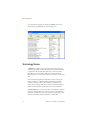
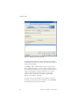
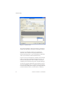
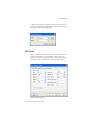
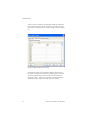
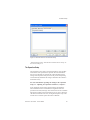
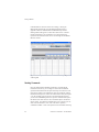
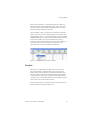
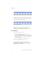

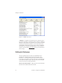
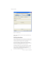
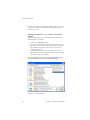
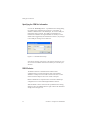
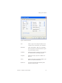
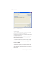
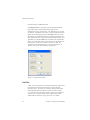
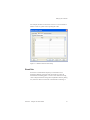
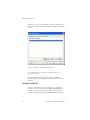
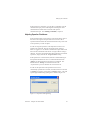
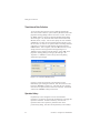
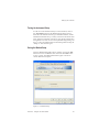
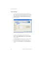
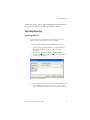
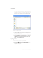
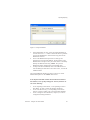
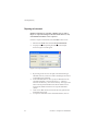
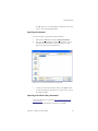
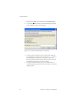
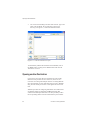
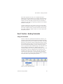
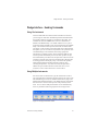
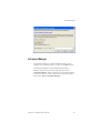
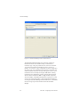
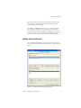
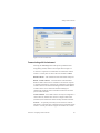
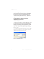
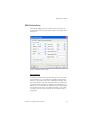
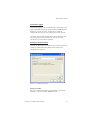
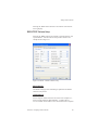


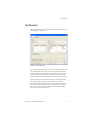
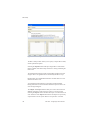
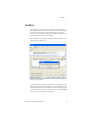
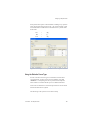
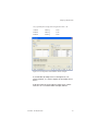
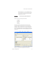

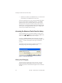
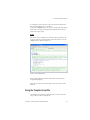

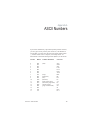
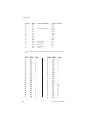

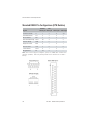
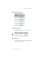


![(met-)acrilico de triciclo[5.2.1.02.6]](http://vs1.manualzilla.com/store/data/006181402_1-cd9631b28198a25c3d43caa802b8e09a-150x150.png)