1
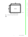
User Manual PPC-1150 Intel® ATOM™ N2600 processor based microcomputer, with 15" color TFT LCD display Copyright The documentation and the software included with this product are copyrighted 2014 by Advantech Co., Ltd. All rights are reserved. Advantech Co., Ltd. reserves the right to make improvements in the products described in this manual at any time without notice. No part of this manual may be reproduced, copied, translated or transmitted in any form or by any means without the prior written permission of Advantech Co., Ltd. Information provided in this manual is intended to be accurate and reliable. However, Advantech Co., Ltd. assumes no responsibility for its use, nor for any infringements of the rights of third parties, which may result from its use. Acknowledgements Intel and Atom are trademarks of Intel Corporation. Microsoft Windows is registered trademark of Microsoft Corp. All other product names or trademarks are properties of their respective owners. Product Warranty (2 years) Advantech warrants to you, the original purchaser, that each of its products will be free from defects in materials and workmanship for two years from the date of purchase. This warranty does not apply to any products which have been repaired or altered by persons other than repair personnel authorized by Advantech, or which have been subject to misuse, abuse, accident or improper installation. Advantech assumes no liability under the terms of this warranty as a consequence of such events. Because of Advantech’s high quality-control standards and rigorous testing, most of our customers never need to use our repair service. If an Advantech product is defective, it will be repaired or replaced at no charge during the warranty period. For outof-warranty repairs, you will be billed according to the cost of replacement materials, service time and freight. Please consult your dealer for more details. If you think you have a defective product, follow these steps: 1. Collect all the information about the problem encountered. (For example, CPU speed, Advantech products used, other hardware and software used, etc.) Note anything abnormal and list any onscreen messages you get when the problem occurs. 2. Call your dealer and describe the problem. Please have your manual, product, and any helpful information readily available. 3. If your product is diagnosed as defective, obtain an RMA (return merchandize authorization) number from your dealer. This allows us to process your return more quickly. 4. Carefully pack the defective product, a fully-completed Repair and Replacement Order Card and a photocopy proof of purchase date (such as your sales receipt) in a shippable container. A product returned without proof of the purchase date is not eligible for warranty service. 5. Write the RMA number visibly on the outside of the package and ship it prepaid to your dealer. PPC-1150 User Manual Part No. 200K115010 Edition 1 Printed in China June 2014 ii Declaration of Conformity FCC Class A Note: This equipment has been tested and found to comply with the limits for a Class A digital device, pursuant to part 15 of the FCC Rules. These limits are designed to provide reasonable protection against harmful interference when the equipment is operated in a commercial environment. This equipment generates, uses, and can radiate radio frequency energy and, if not installed and used in accordance with the instruction manual, may cause harmful interference to radio communications. Operation of this equipment in a residential area is likely to cause harmful interference in which case the user will be required to correct the interference at his own expense. Technical Support and Assistance 1. 2. Visit the Advantech web site at http://support.advantech.com where you can find the latest information about the product. Contact your distributor, sales representative, or Advantech's customer service center for technical support if you need additional assistance. Please have the following information ready before you call: – Product name and serial number – Description of your peripheral attachments – Description of your software (operating system, version, application software, etc.) – A complete description of the problem – The exact wording of any error messages iii PPC-1150 User Manual Safety Instructions 1. 2. 3. Read these safety instructions carefully. Keep this User Manual for later reference. Disconnect this equipment from any AC outlet before cleaning. Use a damp cloth. Do not use liquid or spray detergents for cleaning. 4. For plug-in equipment, the power outlet socket must be located near the equipment and must be easily accessible. 5. Keep this equipment away from humidity. 6. Put this equipment on a reliable surface during installation. Dropping it or letting it fall may cause damage. 7. The openings on the enclosure are for air convection. Protect the equipment from overheating. DO NOT COVER THE OPENINGS. 8. Make sure the voltage of the power source is correct before connecting the equipment to the power outlet. 9. Position the power cord so that people cannot step on it. Do not place anything over the power cord. 10. All cautions and warnings on the equipment should be noted. 11. If the equipment is not used for a long time, disconnect it from the power source to avoid damage by transient overvoltage. 12. Never pour any liquid into an opening. This may cause fire or electrical shock. 13. Never open the equipment. For safety reasons, the equipment should be opened only by qualified service personnel. 14. If one of the following situations arises, get the equipment checked by service personnel: The power cord or plug is damaged. Liquid has penetrated into the equipment. The equipment has been exposed to moisture. The equipment does not work well, or you cannot get it to work according to the user's manual. The equipment has been dropped and damaged. The equipment has obvious signs of breakage. 15. DO NOT LEAVE THIS EQUIPMENT IN AN ENVIRONMENT WHERE THE STORAGE TEMPERATURE MAY GO BELOW -20° C (-4° F) OR ABOVE 60° C (140° F). THIS COULD DAMAGE THE EQUIPMENT. THE EQUIPMENT SHOULD BE IN A CONTROLLED ENVIRONMENT. 16. CAUTION: DANGER OF EXPLOSION IF BATTERY IS INCORRECTLY REPLACED. REPLACE ONLY WITH THE SAME OR EQUIVALENT TYPE RECOMMENDED BY THE MANUFACTURER, DISCARD USED BATTERIES ACCORDING TO THE MANUFACTURER'S INSTRUCTIONS. The sound pressure level at the operator's position according to IEC 704-1:1982 is no more than 70 dB (A). DISCLAIMER: This set of instructions is given according to IEC 704-1. Advantech disclaims all responsibility for the accuracy of any statements contained herein. PPC-1150 User Manual iv Safety Precaution - Static Electricity Follow these simple precautions to protect yourself from harm and the products from damage. To avoid electrical shock, always disconnect the power from your PC chassis before you work on it. Don't touch any components on the CPU card or other cards while the PC is on. Disconnect power before making any configuration changes. The sudden rush of power as you connect a jumper or install a card may damage sensitive electronic components. v PPC-1150 User Manual PPC-1150 User Manual vi Contents Chapter 1 General Information ............................1 1.1 1.2 Introduction ............................................................................................... 2 Specifications ............................................................................................ 2 1.2.1 General Specification.................................................................... 2 1.2.2 Power Specifications..................................................................... 3 1.2.3 Touchscreen Specifications .......................................................... 3 1.2.4 Environment Specifications........................................................... 3 1.2.5 Certification ................................................................................... 3 1.2.6 IP Grade........................................................................................ 3 Dimensions ............................................................................................... 4 Figure 1.1 PPC-1150 dimensions................................................ 5 1.3 Chapter 2 System Installation & Setup ...............7 2.1 Quick Start Guide...................................................................................... 8 Figure 2.1 Front panel ................................................................ 8 Figure 2.2 Side view .................................................................... 9 Install Memory Card ................................................................................ 10 Install the mSATA and SATA HDD ......................................................... 12 Figure 2.3 Install mSATA........................................................... 12 Install Wireless LAN Card ....................................................................... 13 Installation Procedures............................................................................ 15 2.5.1 Connecting Power Cord.............................................................. 15 2.5.2 Connecting Keyboard and Mouse............................................... 15 2.5.3 Switching on Power .................................................................... 15 Hook Installation...................................................................................... 16 Figure 2.4 Hook Installation ....................................................... 16 2.2 2.3 2.4 2.5 2.6 Chapter Chapter 3 Jumper Configuration .......................17 3.1 3.2 PCM-8206B Front View .......................................................................... 18 Figure 3.1 Front view ................................................................. 18 Jumper Setting ........................................................................................ 19 4 Software Configuration .....................21 4.1 4.2 Install Divers............................................................................................ 22 BIOS Setup ............................................................................................. 22 4.2.1 Enter BIOS.................................................................................. 22 4.2.2 Display Brightness Adjustment ................................................... 23 4.2.3 COM2 Mode Selection (RS232/RS422/RS485) ......................... 24 4.2.4 COM4 Mode Selection (RS422/RS485) ..................................... 25 vii PPC-1150 User Manual PPC-1150 User Manual viii Chapter 1 1 General Information This chapter gives background information on the PPC-1150 panel PC. Sections include: Introduction Specifications Dimensions 1.1 Introduction The PPC-1150 is an Intel Atom N2600 based Panel PC with a 15" color TFT LCD, which can be installed in versatile applications under harsh environment. The streamlined design, slim and compact chassis makes it convenient and space-saving. The fanless design ensures the stable operation of PPC-1150 in any harsh industrial environment. It is equipped with the most commonly used interfaces, such as dual Gigabit Ethernet ports, four USB ports and one audio output interface. The PPC-1150 also provides five COM ports, including three RS-232, one RS-232/422/ 485 and one RS-422/485, making it the ideal choice of industrial applications with multiple COM ports. In addition, PPC-1150 supports wireless network, mSATA or HDD storage options and optional 2 x 2W speakers. The above mentions features embodies the humanized design of the product and meets the requirements of a wide range of customers. 1.2 Specifications 1.2.1 General Specification Product PPC-1150 LCD Specification 15’’ LCD Display Type 15" TFT LCD (LED backlight) Max. Resolution 1024 x 768 Color 262K Pixel Pitch 0.297 x 0.297mm Viewing Angle 80 (left), 80 (right), 70 (top), 70 (bottom) Brightness 250 cd/m2 (Typ.) Contrast 700 Backlight Lifecycle 50, 000 hours Weight 5.3 kg Dimensions 396 x 317 x 57 (mm) (15.6” x 12.5” x 2.24”) CPU Model Intel Atom N2600 Chipset Intel N2600 + NM10 Memory One 204 pin SO-DIMM slot, up to 2G DDR3 (667MHz) Storage 2.5" SATA HDD Network 2 x Gigabit Ethernet ports I/O Ports 5 x COM Ports: 1 x RS-232/422/485, 1 x RS-422/485, 3 x RS-232 4 x USB 2.0 ports 2 x Gigabit Ethernet ports 1 x VGA, 1 x DP 1 x audio out port 2 x 2 W speaker (optional) 1 x Phoenix power port, 1 x Power switch Expansion Slot 1 x PCIe x4 (standard) 1 x PCI (in the accessory box) Frequency 1.6 GHz Cache 1 MB Additional Expansion Slot 1 x Mini PCIe full-size slot and 1 x mSATA card slot System PPC-1150 User Manual WES 09/WES 7/Win CE 7.0/Win XP Pro/Win 7/Linux 2 Power 20 W (test system: Windows7 32bit) 18 W (test system: WindowsXP32bit) Output Voltage 12-30 VDC, 5~2 A Chapter 1 1.2.2 Power Specifications Note 1: PPC-1150's power test conditions are as follows: Test Configuration Burn-in 7.0 Memory: Transcend DDR3 1333 SODIMM 2G x 1 HDD: WD 500G WD5000BPKX 2.5" SATA I/O: COM Port RS232 Loopback x4, USB2.0 Device x3, USB Mouse x1 1.2.3 Touchscreen Specifications Type Five-wire resistive touchscreen Light Transmission 81%+/-3% Controller COM interface Durability 36 million times 1.2.4 Environment Specifications Operation Temperature 0 ~ 50°C (32 ~ 122°F) Storage Temperature -20 ~ 60°C (-4 ~ 140°F) Relative Temperature 10 ~ 95% @ 40°C (non-condensing) Shock 10 G peak acceleration (11 msec duration) Vibration 5 ~ 500 Hz 1 G RMS 1.2.5 Certification EMC FCC Class A Safety CCC 1.2.6 IP Grade Front Panel IP Grade IP65 compliant 3 PPC-1150 User Manual General Information Test Software 1.3 Dimensions PPC-1150 User Manual 4 Chapter 1 Figure 1.1 PPC-1150 dimensions Note! Specification of mounting VESA screws: M4*6L 5 PPC-1150 User Manual General Information Unit:mm PPC-1150 User Manual 6 Chapter 2 2 System Installation & Setup Sections include: Quick Installation Guide Install Memory Install mSATA and SATA HDD Install Wireless LAN Card Hook Installation 2.1 Quick Start Guide Before you start to set up the panel PC, take a moment to become familiar with the locations and functions of the controls, connectors and ports. Front view: Figure 2.1 Front panel Note! There are no LED indicators on the front panel. PPC-1150 User Manual 8 1 Chapter 2 Side view: 3 1 Figure 2.2 Side view Items in red circles are VESA screw holes (screw specification: M4*6) 1. Antenna hole (two) 2. Panel Mount Bracket holes 3. Vent hole I/O interfaces: Please refer to the figure below: COM1:RS232, COM2:RS232/422/485, COM5:RS232 9 COM3:RS232, COM4:RS422/485, PPC-1150 User Manual System Installation & Setup 2 2.2 Install Memory Card 1. Loosen the eight screws on the rear cover and two on both sides. PPC-1150 User Manual 10 Chapter 2 System Installation & Setup 2. Insert the memory card into the specified DIMM slot. 11 PPC-1150 User Manual 2.3 Install the mSATA and SATA HDD 1. mSATA installation Plug the mSATA into the mainboard interface and secure it with two screws provided in the accessary box. Figure 2.3 Install mSATA 2. SATA HDD installation a. Take out four screws from the accessary box to fix SATA HDD to the bracket. PPC-1150 User Manual 12 System Installation & Setup 2.4 Install Wireless LAN Card 1. Insert the wireless LAN card into the mainboard interface and fix it. 13 Chapter 2 b. Connect the HDD cable and notice the wiring. Do not let the HDD cable press the data cable. PPC-1150 User Manual 2. Secure the antenna as shown below (eudipleural, two places) 3. Connect the antenna to the wireless LAN card and attach the external antenna terminals. PPC-1150 User Manual 14 2.5.1 Connecting Power Cord The panel PC can only be powered through an DC electrical outlet (12 - 30 V). Pay attention to the positive and negative polarity of the DC input. Follow these procedures to connect the power cord: 1. Connect the female end of the power cord to the DC inlet of the panel PC. 2. Connect the 3-pin male plug of the power cord to an electrical outlet. Chapter 2 2.5 Installation Procedures System Installation & Setup 2.5.2 Connecting Keyboard and Mouse Connect the mouse and keyboard to the USB interface of the panel PC. 2.5.3 Switching on Power Press the power switch located at the left of the I/O section. 15 PPC-1150 User Manual 2.6 Hook Installation How to Install Hook Plastic Tap Use tweezers to disassemble the plastic taps on four sides of the panel PC. Hook After the panel PC is installed in the cabinet, prepare the hook. Place the hook in the hole as the picture shows to hookup the panel PC. Screw Fasten the screw to fix the panel PC. Figure 2.4 Hook Installation PPC-1150 User Manual 16 Chapter 3 3 Jumper Configuration Sections include: PCM-8206B Front View Jumper Settings 3.1 PCM-8206B Front View Figure 3.1 Front view Connectors Function CN6 LVDS CN54 Backlight CN62 COM5 CN21 Reset button CN15 LCD size select CN25 LPC CN17 mSATA CN14 Touch screen interface JP1 AT/ATX Select / Clear CMOS CN7 Mini PCIE CN5 SATA CN13 SATA power connector CN65 COM4 CN63 COM4 RS422 120Ω resistor select CN58 COM2 RS422 120Ω resistor select CN19 COM1/COM2 Pin9 voltage select PPC-1150 User Manual 18 Graphic AT/ATX Select / Clear CMOS (1-3) P1 CMOS Clear (3-5)(Default) P2 Normal (2-4) P3 AT Power (4-6)(Default) P4 ATX power CN15 Graphic Function Jumper Configuration JP1 Chapter 3 3.2 Jumper Settings (1-2) (Default) P5 1024*768 Panel (3-4) P6 800*600 Panel (5-6) P7 Reserved (7-8) P8 Touch Disable 19 PPC-1150 User Manual CN19 Graphic COM1/COM2 Pin9 Voltage Select (1-3)(2-4) (Default) P9 RI (3-5)(4-6) P10 5V(COM1/COM2 Pin9) Max?500mA (7-9)(8-10) P11 12V(COM1/COM2 Pin9) Max:250mA CN58 Graphic COM3 RS422 120Ω Resistor Select (1-2)(3-4) P13 Add 120Ω resistor CN63 Graphic COM4 RS422 120Ω Resistor Select (1-2)(3-4) P15 Add 120Ω resistor PPC-1150 User Manual 20 Chapter 4 Software Configuration Sections include: Install Drivers BIOS Setup Program 4 4.1 Install Divers When first using the system, users need to set up corresponding drivers, in order to ensure all functions are normal. Please take out the DVD-ROM from the accessory box and open it in the system: Follow the instructions to install the drivers. The drivers in the accompanied DVDROM may not be the latest version, if needed, please find it at: http://www.advantech.com/ 4.2 BIOS Setup 4.2.1 Enter BIOS Start the computer and press “Delete” key to enter BIOS. Press “F4” to save and exit after any configuration, or the configuration won't be saved in BIOS. PPC-1150 User Manual 22 Select “Brightness Control” under “Host Bridge”. 2. Select “Intel IGD Configurationl”. Software Configuration 1. Chapter 4 4.2.2 Display Brightness Adjustment 23 PPC-1150 User Manual 3. There are 6 options under “Brightness Manual Control”. 4.2.3 COM2 Mode Selection (RS232/RS422/RS485) 1. Select “Super IO Configuration” under “Advanced”. PPC-1150 User Manual 24 Select “Serial Port 2 Configuration” and then select the operation mode of COM2 by "Serial Port2 Mode". Software Configuration 4.2.4 COM4 Mode Selection (RS422/RS485) 1. Select “Super IO Configuration” under “Advanced”. 25 Chapter 4 2. PPC-1150 User Manual 2. Select “Serial Port 4 Configuration” and then select the operation mode of COM4 by "Serial Port4 Mode". PPC-1150 User Manual 26 Chapter 4 Software Configuration PPC-1150 User Manual 27 www.advantech.com Please verify specifications before quoting. This guide is intended for reference purposes only. All product specifications are subject to change without notice. No part of this publication may be reproduced in any form or by any means, electronic, photocopying, recording or otherwise, without prior written permission of the publisher. All brand and product names are trademarks or registered trademarks of their respective companies. © Advantech Co., Ltd. 2014