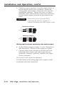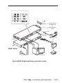
1
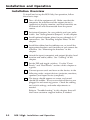
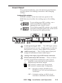
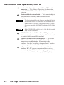
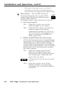
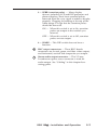
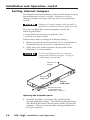
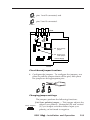
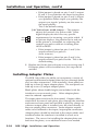
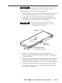
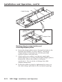
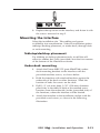
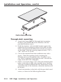
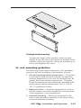
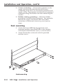
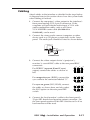
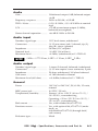
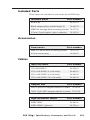
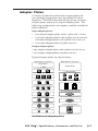
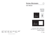
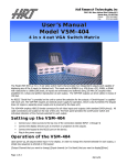
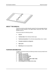
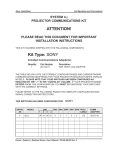
User’s Manual
RGB 168xi
VGA Interface with Stereo Audio and ADSP™
68-550-01 Rev. B
11 08
Precautions
Safety Instructions • English
This symbol is intended to alert the user of important
operating and maintenance (servicing) instructions
in the literature provided with the equipment.
This symbol is intended to alert the user of the
presence of uninsulated dangerous voltage within
the product's enclosure that may present a risk of
electric shock.
Caution
Read Instructions • Read and understand all safety and operating
instructions before using the equipment.
Retain Instructions • The safety instructions should be kept for future
reference.
Follow Warnings • Follow all warnings and instructions marked on the
equipment or in the user information.
Avoid Attachments • Do not use tools or attachments that are not
recommended by the equipment manufacturer because they may be
hazardous.
Consignes de Sécurité • Français
Ce symbole sert à avertir l’utilisateur que la
documentation fournie avec le matériel contient des
instructions importantes concernant l’exploitation
et la maintenance (réparation).
Ce symbole sert à avertir l’utilisateur de la présence
dans le boîtier de l’appareil de tensions dangereuses
non isolées posant des risques d’électrocution.
Attention
Lire les instructions• Prendre connaissance de toutes les consignes de
sécurité et d’exploitation avant d’utiliser le matériel.
Conserver les instructions• Ranger les consignes de sécurité afin de
pouvoir les consulter à l’avenir.
Respecter les avertissements • Observer tous les avertissements et
consignes marqués sur le matériel ou présentés dans la documentation
utilisateur.
Eviter les pièces de fixation • Ne pas utiliser de pièces de fixation ni
d’outils non recommandés par le fabricant du matériel car cela
risquerait de poser certains dangers.
Sicherheitsanleitungen • Deutsch
Dieses Symbol soll den Benutzer auf wichtige
Anleitungen zur Bedienung und Wartung
(Instandhaltung) in der Dokumentation hinweisen,
die im Lieferumfang dieses Gerätes enthalten ist.
Dieses Symbol soll den Benutzer darauf aufmerksam
machen, daß im Inneren des Gehäuses dieses
Produktes gefährliche Spannungen, die nicht isoliert
sind und die einen elektrischen Schock verursachen
können, herrschen.
Achtung
Lesen der Anleitungen • Bevor Sie das Gerät zum ersten Mal verwenden,
sollten Sie alle Sicherheits-und Bedienungsanleitungen genau
durchlesen und verstehen.
Aufbewahren der Anleitungen • Die Sicherheitsanleitungen sollten
aufbewahrt werden, damit Sie später darauf zurückgreifen können.
Befolgen der Warnhinweise • Befolgen Sie alle Warnhinweise und
Anleitungen auf dem Gerät oder in der Benutzerdokumentation.
Keine Zusatzgeräte • Verwenden Sie keine Werkzeuge oder Zusatzgeräte,
die nicht ausdrücklich vom Hersteller empfohlen wurden, da diese eine
Gefahrenquelle darstellen können.
Instrucciones de seguridad • Español
Este símbolo se utiliza para advertir al usuario sobre
instrucciones importantes de operación y
mantenimiento (o cambio de partes) que se desean
destacar en el contenido de la documentación
suministrada con los equipos.
Este símbolo se utiliza para advertir al usuario sobre
la presencia de elementos con voltaje peligroso sin
protección aislante, que puedan encontrarse dentro
de la caja o alojamiento del producto, y que puedan
representar riesgo de electrocución.
Precaucion
Leer las instrucciones • Leer y analizar todas las instrucciones de
operación y seguridad, antes de usar el equipo.
Conservar las instrucciones • Conservar las instrucciones de seguridad
para futura consulta.
Obedecer las advertencias • Todas las advertencias e instrucciones
marcadas en el equipo o en la documentación del usuario, deben ser
obedecidas.
Evitar el uso de accesorios • No usar herramientas o accesorios que no
sean especificamente recomendados por el fabricante, ya que podrian
implicar riesgos.
Warning
Power sources • This equipment should be operated only from the power source
indicated on the product. This equipment is intended to be used with a main
power system with a grounded (neutral) conductor. The third (grounding) pin is
a safety feature, do not attempt to bypass or disable it.
Power disconnection • To remove power from the equipment safely, remove all
power cords from the rear of the equipment, or the desktop power module (if
detachable), or from the power source receptacle (wall plug).
Power cord protection • Power cords should be routed so that they are not likely to
be stepped on or pinched by items placed upon or against them.
Servicing • Refer all servicing to qualified service personnel. There are no userserviceable parts inside. To prevent the risk of shock, do not attempt to service
this equipment yourself because opening or removing covers may expose you to
dangerous voltage or other hazards.
Slots and openings • If the equipment has slots or holes in the enclosure, these are
provided to prevent overheating of sensitive components inside. These openings
must never be blocked by other objects.
Lithium battery • There is a danger of explosion if battery is incorrectly replaced.
Replace it only with the same or equivalent type recommended by the
manufacturer. Dispose of used batteries according to the manufacturer's
instructions.
Avertissement
Alimentations• Ne faire fonctionner ce matériel qu’avec la source d’alimentation
indiquée sur l’appareil. Ce matériel doit être utilisé avec une alimentation
principale comportant un fil de terre (neutre). Le troisième contact (de mise à la
terre) constitue un dispositif de sécurité : n’essayez pas de la contourner ni de la
désactiver.
Déconnexion de l’alimentation• Pour mettre le matériel hors tension sans danger,
déconnectez tous les cordons d’alimentation de l’arrière de l’appareil ou du
module d’alimentation de bureau (s’il est amovible) ou encore de la prise secteur.
Protection du cordon d’alimentation • Acheminer les cordons d’alimentation de
manière à ce que personne ne risque de marcher dessus et à ce qu’ils ne soient pas
écrasés ou pincés par des objets.
Réparation-maintenance • Faire exécuter toutes les interventions de réparationmaintenance par un technicien qualifié. Aucun des éléments internes ne peut être
réparé par l’utilisateur. Afin d’éviter tout danger d’électrocution, l’utilisateur ne
doit pas essayer de procéder lui-même à ces opérations car l’ouverture ou le
retrait des couvercles risquent de l’exposer à de hautes tensions et autres dangers.
Fentes et orifices • Si le boîtier de l’appareil comporte des fentes ou des orifices,
ceux-ci servent à empêcher les composants internes sensibles de surchauffer. Ces
ouvertures ne doivent jamais être bloquées par des objets.
Lithium Batterie • Il a danger d'explosion s'll y a remplacment incorrect de la
batterie. Remplacer uniquement avec une batterie du meme type ou d'un ype
equivalent recommande par le constructeur. Mettre au reut les batteries usagees
conformement aux instructions du fabricant.
Vorsicht
Stromquellen • Dieses Gerät sollte nur über die auf dem Produkt angegebene
Stromquelle betrieben werden. Dieses Gerät wurde für eine Verwendung mit
einer Hauptstromleitung mit einem geerdeten (neutralen) Leiter konzipiert. Der
dritte Stift oder Kontakt ist für einen Erdschluß, und stellt eine
Sicherheitsfunktion dar und sollte nicht umgangen oder außer Betrieb gesetzt
werden.
Stromunterbrechung • Um das Gerät auf sichere Weise vom Netz zu trennen,
sollten Sie alle Netzkabeln aus der Rückseite des Gerätes oder aus dem DesktopStrommodul (falls dies möglich ist) oder aus der Wandsteckdose ziehen.
Schutz des Netzkabels • Netzkabel sollten stets so verlegt werden, daß sie nicht
im Weg liegen und niemand darauf treten kann oder Objekte darauf- oder
unmittelbar dagegengestellt werden können.
Wartung • Alle Wartungsmaßnahmen sollten nur von qualifiziertem
Servicepersonal durchgeführt werden. Im Inneren des Gerätes sind keine Teile
enthalten, die vom Benutzer gewartet werden können. Zur Vermeidung eines
elektrischen Schocks versuchen Sie in keinem Fall, dieses Gerät selbst zu warten,
da beim Öffnen oder Entfernen der Abdeckungen die Gefahr eines elektrischen
Schlags oder andere Gefahren bestehen.
Schlitze und Öffnungen • Wenn das Gerät Schlitze oder Löcher im Gehäuse
aufweist, dienen diese zur Vermeidung einer Überhitzung der empfindlichen
Teile im Inneren. Diese Öffnungen dürfen niemals von anderen Objekten
blockiert werden.
Litium-Batterie • Explosionsgefahr, falls die Batterie nicht richtig ersetzt wird.
Ersetzen Sie nur durch diegleiche oder einen vergleichbaren Batterietyp, der
auch vom Hersteller empfohlen wird. Entsorgung der verbrauchten Batterien
bitte gemäß den Herstelleranweisungen.
Advertencia
Alimentación eléctrica • Este equipo debe conectarse únicamente a la fuente/tipo
de alimentación eléctrica indicada en el mismo. La alimentación eléctrica de este
equipo debe provenir de un sistema de distribución general con conductor
neutro a tierra. La tercera pata (puesta a tierra) es una medida de seguridad, no
puentearia ni eliminaria.
Desconexión de alimentación eléctrica • Para desconectar con seguridad la
acometida de alimentación eléctrica al equipo, desenchufar todos los cables de
alimentación en el panel trasero del equipo, o desenchufar el módulo de
alimentación (si fuera independiente), o desenchufar el cable del receptáculo de
la pared.
Protección del cables de alimentación • Los cables de alimentación eléctrica se
deben instalar en lugares donde no sean pisados ni apretados por objetos que se
puedan apoyar sobre ellos.
Reparaciones/mantenimiento • Solicitar siempre los servicios técnicos de personal
calificado. En el interior no hay partes a las que el usuario deba acceder. Para
evitar riesgo de electrocución, no intentar personalmente la reparación/
mantenimiento de este equipo, ya que al abrir o extraer las tapas puede quedar
expuesto a voltajes peligrosos u otros riesgos.
Ranuras y aberturas • Si el equipo posee ranuras o orificios en su caja/alojamiento,
es para evitar el sobrecalientamiento de componentes internos sensibles. Estas
aberturas nunca se deben obstruir con otros objetos.
Batería de litio • Existe riesgo de explosión si esta batería se coloca en la posición
incorrecta. Cambiar esta batería únicamente con el mismo tipo (o su equivalente)
recomendado por el fabricante. Desachar las baterías usadas siguiendo las
instrucciones del fabricante.
FCC Class A Notice
This equipment has been tested and found to comply with the limits for a
Class A digital device, pursuant to part 15 of the FCC Rules. These limits are
designed to provide reasonable protection against harmful interference when the
equipment is operated in a commercial environment. This equipment generates,
uses and can radiate radio frequency energy and, if not installed and used in
accordance with the instruction manual, may cause harmful interference to radio
communications. Operation of this equipment in a residential area is likely to
cause harmful interference, in which case the user will be required to correct the
interference at his own expense.
N This unit was tested with shielded cables on the peripheral devices. Shielded
cables must be used with the unit to ensure compliance.
Table of Contents
Chapter 1 • Introduction .......................................................... 1-1
About this Manual ................................................................ 1-2
xi ............................................................. 1-2
About the RGB 168xi
Features ...................................................................................... 1-2
Chapter 2 • Installation and Operation .......................... 2-1
Installation Overview ......................................................... 2-2
Front Panel ................................................................................ 2-3
Rear Panel ................................................................................. 2-5
Setting Internal Jumpers ................................................... 2-8
Installing Adapter Plates ................................................ 2-10
Mounting the Interface .................................................... 2-13
Tabletop/desktop placement .............................................. 2-13
Under-desk mounting ......................................................... 2-13
Through-desk mounting ...................................................... 2-14
UL rack mounting guidelines ............................................... 2-15
Rack mounting ..................................................................... 2-16
Cabling ...................................................................................... 2-17
Troubleshooting .................................................................... 2-20
Appendix A • Specifications, Accessories, and Part
Numbers .............................................................................................. A-1
Specifications ......................................................................... A-2
Included Parts ......................................................................... A-5
Accessories .............................................................................. A-5
Cables ......................................................................................... A-5
Adapter Plates ....................................................................... A-7
All trademarks mentioned in this manual are the properties of their respective
owners.
68-550-01 Rev. B
11 08
RGB 168xi
xi • Table of Contents
TOC-i
Table of Contents, cont’d
xi • Table of Contents
TOC-ii RGB 168xi
RGB 168xi
xi
1
Chapter One
Introduction
About this Manual
About the RGB 168xi
Features
Introduction, cont’d
Introduction
About this Manual
This manual contains information about the RGB 168xi
universal analog interface and how to operate and
configure it.
About the RGB 168xi
xi
The RGB 168xi is a computer-video and stereo audio
interface with 300 MHz (-3dB) video bandwidth. This
interface has a horizontal frequency range of 15 kHz to
125 kHz, so it can be used with any type of analog
computer signal, including those from VGA to UXGA-2,
Mac, Quadra, Sun, and SGI computers.
Features
This section highlights the main features of the RGB 168xi
interface. See the installation chapter for a detailed
description of front and rear panel features.
Internal power supply — Uses a standard IEC power cord.
Front panel AC outlet — Peripherals or laptop computers
can be plugged into the unswitched front panel AC
outlet for a convenient power connection. This
feature is not available in Europe.
Furniture and rack mountability — The RGB 168xi can be
mounted under a desk or podium with optional
hardware, or it can be mounted in a rack or through
a desk or other furniture with included vertical
mounting brackets.
Active stereo audio — Unbalanced stereo audio input via a
front panel jack is output as balanced, line level
stereo audio on the rear panel captive screw
connector.
Horizontal shift control — The interface features front
panel horizontal centering control.
Sync stripping — Incoming sync will be stripped from the
red, green, and blue signals.
RGBHV, RGBS, or RGsB output — RGBHV can be output
simultaneously with RGBS. Sync on green (RGsB)
output can be DIP switch selected.
Advanced Digital Sync Processing™ (ADSP™) — ADSP
allows sync processing operations, such as horizontal
centering, to occur without affecting the signal’s sync
timing. This allows horizontal centering to be
applied to signals that are output to digital display
1-2
RGB 168xi
xi • Introduction
devices such as LCD projectors, DLP projectors and
plasma displays. A rear panel DIP switch allows an
alternative, Digital Display Sync Processing™
(DDSP™), to be used instead.
Gain/peaking control — To compensate for signal
degradation caused by long cable lengths, use this
rear panel toggle switch to increase output voltages.
Serration pulse — This feature allows serration pulses to
either be present or not present at the output.
Serration pulses are required for some displays.
Pass-through connectors — A wide assortment
of architectural adapter plates is available for
installation on these interfaces to allow convenient
pass-through A/V connections.
Buffered local monitor output — A 15-pin HD female
connector provides a front panel buffered output for
a local monitor.
ID bit termination — Two front panel DIP switches
provide ID bit termination on pins 4 and/or 11 of the
local monitor output.
RGB 168xi
xi • Introduction
1-3
Introduction, cont’d
1-4
RGB 168xi
xi • Introduction
RGB 168xi
xi
2
Chapter Two
Installation and Operation
Installation Overview
Front Panel
Rear Panel
Setting Internal Jumpers
Installing Adapter Plates
Mounting the Interface
Cabling
Troubleshooting
RGB 168xi
xi • Installation and Operation
Installation and
Operation,
cont’d
Installation
and
Operation
Installation Overview
To install and set up the RGB 168xi for operation, follow
these basic steps:
1
Turn all of the equipment off. Make sure that the
computer, the interface and the output device(s)
(projector or display monitor, and local monitor) are
all turned off and disconnected from the power
source.
2
Set internal jumpers for sync polarity and sync pulse
width. See “Setting Internal Jumpers” in this chapter.
3
Install optional adapter plates for pass-through A/V
connections. See “Installing Adapter Plates” in this
chapter.
4
Install the rubber feet for tabletop use, or install the
appropriate brackets and furniture or rack mount the
interface. See “Mounting the Interface” in this
chapter.
5
Attach the input (computer) and output (display, local
monitor and audio) cables. See “Cabling” in this
chapter.
6
Set the DIP and toggle switches. Use the “Front
Panels” and “Rear Panels” sections of this chapter as
a guide.
7
Connect power cords and turn on the devices in the
following order: output devices (projector, monitors,
speakers) and input device (computer).
8
The image should appear on screen, and sound
should be audible. If not, ensure that all devices are
plugged in and receiving power. Check the cabling
and switch settings, and make adjustments as
needed.
Refer to “Troubleshooting” in this chapter, then call
the Extron customer support hotline, if needed.
2-2
RGB 168xi
xi • Installation and Operation
Front Panel
This section familiarizes you with the front panel features
and the options for making connections and changing
settings.
Setting DIP switches
The DIP switches on the front and rear panels of the
RGB 168xi may be either the rocking type or the sliding
type.
1
2
3
4
1
2
3
4
To set rocking type DIP switches, use a
small screwdriver to depress the
appropriate end of each switch.
To set sliding type DIP switches, use a small
screwdriver to slide (push) the switch to the
On/closed or Off/open position.
ANALOG
ID PIN 4
ID PIN 11
RGB 168
INPUTS
AUDIO
BUFFERED LOCAL
MONITOR OUTPUT
UNSWITCHED
UNIVERSAL INTERFACE W/ADSP
MIN/MAX
H. SHIFT
100-240
2
3
4
6
5
7
8
9
1
2-color power/signal LED — This LED lights amber
to indicate power on only. It lights green to indicate
that power is on and a video signal is also present.
2
Audio input jack — This 3.5 mm stereo input jack
accepts an unbalanced stereo audio input.
3
Analog video input 15-pin HD female connector
4
ID bit termination DIP switches — These switches
provide proper ID bit termination when a local
monitor is not connected to the interface’s
buffered local monitor output.
ID PIN 4
ID PIN 11
1
0.5A MAX.
DIP switch 1 connects pin 4 to ground.
DIP switch 2 connects pin 11 to ground.
ON — Set both switches (ID PIN 4 and
ID PIN 11) to On if no local monitor is
connected.
OFF — Set both switches to Off if a local
monitor is attached to the interface.
RGB 168xi
xi • Installation and Operation
2-3
Installation and Operation, cont’d
5
Buffered local monitor output 15-pin HD female
connector — This allows output to a local monitor.
Set the ID PIN DIP switches to On if this connector is
not used.
6
Horizontal shift control knob — This control adjusts
the horizontal centering of the remote output
display.
The horizontal shift control has no mechanical limits
to rotation. When the minimum or maximum limit
of the control is reached, the picture ceases to move
on screen, and the MIN/MAX indicator LED lights
red.
If the DDSP DIP switch is set to On, the horizontal
shift control is disabled.
2-4
7
MIN/MAX indicator LED — This LED lights red
whenever the lower or upper limits of the horizontal
or vertical shift controls are reached.
8
Optional architectural adapter plates — Up to four
adapter plates for pass-through audio/video
connections can be attached at one time to the
interface. See the “Installing Adapter Plates” section
in this chapter for installation instructions.
9
AC power output connector — An unswitched
standard IEC AC power connector allows you to
connect a peripheral device that requires power. This
feature is not available in Europe (RGB 168xi Int).
RGB 168xi
xi • Installation and Operation
GAIN/
PEAK
100%
SOG
DDSP
SERR
SPARE
Rear Panel
R
G
B
H
V
S
UNITY
100-240
50/60 Hz 0.5A
1
OUTPUT
50%
2
2
3
4
5
6
7
1
AC power input connector — Connect a standard
IEC AC power cord here for power
input (100 VAC to 240 VAC, 50/60 Hz).
2
Cable access openings — Cables attached to the
front panel A/V pass-through architectural adapter
plates exit the enclosure here. Clamp cables in place
with the supplied hardware.
3
Optional output architectural adapter plate — Front
panel input AAP A/V connectors can be wired here
to pass-through output connectors.
4
3-position gain/peaking switch — Use this toggle
switch to compensate for signal degradation caused
by long (over about 125 feet) cable lengths. Choose
the setting that provides the best image on the
output display device. Select from these options:
• Unity (no gain or peaking) — The output level is
the same as that of the input and with no
added peaking.
• 50% — This setting increases the output signal
level and adds 50% of the maximum peaking
to the signal.
• 100% — This setting increases the output signal
level and adds 100% of the maximum peaking
to the signal.
If the signal cable between the interface and the
display device is shorter than 125 feet, and the gain/
peak switch is set to a setting other than unity, the
image may be overly bright (overcompensated).
RGB 168xi
xi • Installation and Operation
2-5
Installation and Operation, cont’d
If the edges of the image seem to exceed their
boundaries or if thin lines and sharp edges look
thick and fuzzy, try changing the gain/peak setting.
DIP switches — The four DIP switches on
the rear panel control sync on green (SOG)
output, Digital Display Sync Processing and
serration pulse removal.
The fourth switch is a spare and it has no function.
SOG
DDSP
SERR
SPARE
5
1 — SOG (sync on green)
ON — When this switch is set to On, the
interface outputs sync on green.
OFF — When the SOG switch is set to Off, the
interface outputs both separate
horizontal and vertical sync (on the H
and V connectors) and composite sync
(on the S connector) for RGBHV or
RGBS, respectively.
2 — DDSP™ (Digital Display Sync Processing™)
This feature may be necessary for digital display
devices such as LCD (liquid crystal display), DLP
(digital light processing) and plasma displays.
Use this option if the image still is not displayed
properly after all other options, such as serration
pulse removal and video termination changes,
have been explored.
ON — When this switch is set to On, the
interface uses Digital Display Sync
Processing instead of Advanced Digital
Sync Processing™. DDSP does not
process the sync signal.
DDSP disables horizontal and vertical shift
controls.
OFF — When this switch is set to Off, the
interface performs sync processing
operations, such as horizontal shifting,
with ADSP.
2-6
RGB 168xi
xi • Installation and Operation
3 — SERR (serration pulse) — Many display
devices, including LCD and DLP projectors and
plasma displays, must have serration pulses
removed from the sync signal in order to display
properly. Flagging or bending at the top of the
video image is a sign that the serration pulses
should be removed.
ON — When this switch is set to On, serration
pulses are output in the vertical sync
interval.
OFF — When this switch is set to Off, serration
pulses are not output.
4 — SPARE — This DIP switch does not have a
function.
6
BNC output connectors — These BNC female
connectors are for red, green, and blue video output,
and horizontal, vertical and composite sync output.
7
Stereo audio output connector — This 3.5 mm,
5-conductor captive screw connector is used for
audio output. See “Cabling” in this chapter for a
wiring guide.
RGB 168xi
xi • Installation and Operation
2-7
Installation and Operation, cont’d
Setting Internal Jumpers
The jumpers inside the interface(s) are set at the factory to meet
the requirements of most systems. However, you can
change a jumper setting to meet the needs of a particular
system.
Changes to internal jumper settings must be
performed by authorized service personnel only.
The user-configurable, internal jumpers control the
following functions:
• horizontal and vertical sync polarity, and
• vertical sync pulse width.
Follow these steps to change the jumper settings.
1. Remove power from the interface (if it is connected) by
disconnecting the AC power cord from the unit.
2. Open the cover of the interface (the top half of the
enclosure), as shown below.
Do not touch any switches or electronic
components inside the interface. Doing so
could damage the interface.
Remove (12)
Screws
ED
ITCH
SW
UN
60
AT
0W
TS
MAX
.
Lift Cover
Straight Up
8 xiP
B 16/ADS
RGACE W
RF
TE
L IN
SA
IVER
X
MA
MIN/
ID PIN 14
ID PIN 11
UN
L
CA
LO UT
ED TP
ER OU
FF R
BU NITO
MO
Extron
RGB 168xi
TS ALOG
INPU AN
AU
DIO
Remove #8 Screw
(4 Plcs) Each Side
and Bracket, if Present
Opening the interface cover
3. Note the positions of jumpers J20 and J40 before
changing jumper settings. The following illustration of
the circuit board shows the locations of the J20 and J40
jumpers. There are two possible setting combinations
for 3-pin jumpers:
2-8
RGB 168xi
xi • Installation and Operation
pins 1 and 2 connected, and
1 and 2
pins 2 and 3 connected.
2 and 3
Rear
1
J19
1
J20
J20: Sync polarity
jumper
1
J40
J40: Vertical sync
width jumper
Power Supply
Front
Circuit board jumper locations
4. Configure the jumpers. To configure the jumpers, use
pliers to pull the jumper shunt off the pins, then place
the jumper on the appropriate pins.
Changing jumper settings
The jumpers perform the following functions:
J-20: Sync polarity jumper — This jumper adjusts the
output sync polarity. Horizontal (H) and vertical
(V) sync output can either follow input sync
polarity, or be forced to negative.
Follow Negative
1
RGB 168xi
xi • Installation and Operation
2-9
Installation and Operation, cont’d
• If the jumper is placed on pins 1 and 2, output
H and V sync polarities are forced to negative.
• If the jumper is placed on pins 2 and 3, output
sync polarities follow input sync polarity: the
output sync signals’ polarity are the same as
the input polarity.
This is the default setting.
Wide
Short
1
J-40: Vertical sync width jumper — This jumper
adjusts the vertical sync pulse width. Some
digital display devices have very specific
requirements for incoming sync pulse width. If
no picture displays, the picture cuts in and out,
or the picture is scrambled, try adjusting the
vertical sync pulse width or switching from
ADSP to DDSP.
• If the jumper is placed on pins 1 and 2, the
output vertical sync pulse is
short (narrow).
• If the jumper is placed on pins 2 and 3, the
output vertical sync pulse iswide. This is the
default setting.
5. Replace and fasten the enclosure cover, reversing step 2.
If adapter plates will be installed next, this step can be
omitted.
Installing Adapter Plates
The RGB 168xi offers the ability to incorporate a variety of
optional architectural adapter plates for pass-through audio
and/or video connections. Each interface’s front panel can
hold up to four (4) input adapter plates. The rear panel can
hold up to two (2) output adapter plates.
Blank plates (three double height) are included with the
interface to cover unused spaces. Other adapter plates
must be ordered separately.
The input plates attach to the front panel. Output cables,
attached to the rear of each plate, pass through the interface
enclosure and rear panel and are held in place by clamps or,
where an output plate is installed, may be wired directly to
the rear output plate connectors. Some adapters require
cables to be soldered to the input/output plate connectors.
Adapter plates should be attached to the output cables and
interface before the interface is installed in a rack or in
furniture. The screws for installing the adapter plates are
built into the plates, so no additional screws are needed.
2-10
RGB 168xi
xi • Installation and Operation
Adapter plate installation must be performed
by authorized service personnel only.
Follow these steps to install adapter plates.
1. Make sure that the power is removed from the interface
by disconnecting the AC power cord from the unit.
2. Open the cover of the interface (the top half of the
enclosure), as shown below. Remove the screws from
the enclosure, and lift the cover straight up.
Do not touch any switches or electronic
components inside the interface. Doing so
could damage the interface.
Remove (12)
Screws
ED
ITCH
SW
UN
600
WAT
TS
MAX
.
Lift Cover
Straight Up
8 xiP
B 16/ADS
RGACE W
RF
TE
L IN
SA
IVER
ID PIN 14
ID PIN 11
UN
L
CA
LO UT
ED TP
ER OU
FF R
BU NITO
MO
X
MA
MIN/
Extron
RGB 168xi
TS ALOG
INPU AN
AU
DIO
Remove #8 Screw
(4 Plcs) Each Side
and Bracket, if Present
3. Remove the blank plates from the interface by
unscrewing the nuts that fasten the plates to the inside
of the enclosure.
4. Route the adapter output cables through the rear panel
cable holes and clamps into the enclosure and out the
front panel plate openings, as shown on the facing page.
5. Attach the output cables to the rear connectors of the
front panel adapter plates. Soldering will be required
for some connectors.
RGB 168xi
xi • Installation and Operation
2-11
Installation and Operation, cont’d
Cable Routing
HED
ITC
SW
UN
X.
TS
600
MA
WAT
E
TAG
VOL
HIGH
A
C
IT
U
O
N
xi
68 P
B 1 /ADS
RGACE W
ID PIN 14
ID PIN 11
UN
IVER
SA
L IN
TE
RF
/MAX
MIN
L
CA
LO T
ED PU
ER OUT
FF R
BU NITO
MO
TS ALOG
INPU AN
AU
DIO
Tighten nuts
securely
Adapter Plate
Routing adapter output cables and
attaching adapter plates
6. Insert the adapter plate screws through the holes in the
interface front panel, as shown above. Attach the
adapter plates to the enclosure with the provided
captive washers and #4-40 nuts.
7. Gently pull excess cable(s) out the rear panel cable
clamp openings or, if a rear panel output adapter plate is
being used, connect the cable(s) to the plate
connector(s). Do not strain or damage the cableadapter connections.
8. Fasten the cables in place by tightening the screws on
the cable clamps provided on the rear panel openings.
2-12
RGB 168xi
xi • Installation and Operation
100-240
50/60 Hz 0.5A
9. Replace the top cover on the interface, and fasten it with
the screws removed in step 2.
Mounting the Interface
Select the installation site. Take cabling and power
availability into consideration. Select an installation option:
tabletop/desktop placement, or under-desk, through-desk
or rack mounting.
Tabletop/desktop placement
For tabletop or desktop placement only, install the selfadhesive rubber feet/pads (provided) onto the four corners
of the bottom of the interface enclosure.
Under-desk mounting
1. Attach the Extron MBU 125 (part #70-077-01) underdesk mounting brackets to the interface with the
provided machine screws, as shown below.
2. Hold the interface with attached brackets against the
underside of the desk or other furniture. Mark the
location of holes for screws on the desk.
3. Drill 1/4” (6.4 mm) deep, 3/32” (2.38 mm) diameter
pilot holes in the table or desk at the marked screw
locations from the underside/inside (concealed side) of
the furniture, where the interface will be located.
4. Attach the interface to the installation surface with the
provided wood screws, as shown in the following
illustration.
RGB 168xi
xi • Installation and Operation
2-13
Installation and Operation, cont’d
D
HE
ITC
SW
UN
600
TT
WA
S MA
X.
8 xi
B 16/ADSP
RGCE W
FA
ER
AL
RS
INT
X
/MA
MIN
IVE
ID PIN 14
ID PIN 11
UN
L
CA
LO UT
ED TP
ER OU
FF
BU NITOR
MO
S
UT ALOG
INP AN
DIO
AU
Under-desk mounting
Through-desk mounting
1. Attach the Extron MBD 149 through-desk mounting
brackets (part #70-077-03) to the interface with the
provided machine screws.
2. Hold the interface with attached brackets against the
underside of the mounting surface of the desk or table.
With a soft pencil mark the location of holes for screws
on the desk. Mark the opening, approximately 17.63" x
1.88" (44.77 cm x 4.76 cm).
3. Cut out the material from the installation area with a
jigsaw. Check the opening size by inserting the
interface part way through the hole. If needed, use a
saw, file or sandpaper to enlarge the hole. Smooth the
edges of the hole with sandpaper.
4. Drill 1/4" (6.4 mm) deep, 3/32" (2.38 mm) diameter pilot
holes in the desk or table at the marked screw locations.
The holes should be drilled from the underside or inside
(concealed side) of the furniture, where the interface will
be located.
5. Attach the interface to the desk with the provided wood
screws, as shown in the following illustration.
2-14
RGB 168xi
xi • Installation and Operation
X.
A
M
S
ATT
W
0
60
ED
H
C
IT
SW
N
D
/A
8
W
E
16
C
FA
B
R
G
TE
R
L
A
C UT
LO TP
ED OU
ER R
FF O
U IT
B ON
M
U
N
IV
ER
SA
L
IN
xi
SP
X
A
/M
IN
M
U
ID
PIN
PIN
ID
AU
IO
D
IN
TS NA
PU A
LO
G
14
11
Through-desk mounting
To adjust the height of the interface within the desk,
slightly loosen the screws that attach the brackets to the
interface, adjust the height by sliding the interface up or
down, and retighten the screws.
UL rack mounting guidelines
The following Underwriters Laboratories (UL) guidelines
pertain to the safe installation of the interface in a rack.
1. Elevated operating ambient temperature — If installed
in a closed or multi-unit rack assembly, the operating
ambient temperature of the rack environment may be
greater than room ambient temperature. Therefore,
install the interface in an environment compatible with
the maximum ambient temperature (Tma = +122 °F,
+50 °C) specified by Extron.
2. Reduced air flow — Install the equipment in a rack so
that the amount of air flow required for safe operation
of the equipment is not compromised.
3. Mechanical loading — Mount the equipment in the
rack so that a hazardous condition is not achieved due
to uneven mechanical loading.
RGB 168xi
xi • Installation and Operation
2-15
Installation and Operation, cont’d
4. Circuit overloading — Connect the equipment to the
supply circuit and consider the effect that circuit
overloading might have on overcurrent protection and
supply wiring. Appropriate consideration of equipment
nameplate ratings should be used when addressing this
concern.
5. Reliable earthing (grounding) — Maintain reliable
grounding of rack-mounted equipment. Pay particular
attention to supply connections other than direct
connections to the branch circuit (e.g. use of power
strips).
Rack mounting
1. Attach the Extron MBD 149 through-desk/rack
mounting brackets (part #70-077-03) to the interface
with the provided machine screws, as shown below.
2. Attach the interface to the rack with the provided
machine screws.
ED
ITCH
SW
UN
.
TS
600
xi
68 P
B 1 /ADS
RGACE W
RF
TE
L IN
SA
IVER
X
MA
MIN/
ID PIN 14
ID PIN 11
UN
L
CA
LO UT
ED TP
ER OU
FF
BU ITOR
MON
TS ALOG
INPU AN
AU
DIO
Rack mounting
2-16
RGB 168xi
xi • Installation and Operation
WAT
MAX
Cabling
Attach cables to the interface as detailed in the steps below.
A diagram later in this section shows how the system looks
when cabling is finished.
1. Connect the computer’s video output to the interface’s
front panel analog/ECL 9-pin D connector. If the
computer will provide the audio input, a VGA with
audio combination cable, such as an Extron
VGA M MHRA series cable (#26-490-01 to
#26-490-05), can be used.
2. Connect the stereo audio source (computer or other
device such as a CD player or tape deck) to the front
panel. The audio jack should be wired as shown below.
Tip (L)
Ring (R)
Sleeve ( )
Unbalanced
3. Connect the video output device’s (projector’s,
monitor’s) coaxial BNC cable to the rear panel BNC
connectors.
For RGBHV (separate H and V sync)
output, connect the cables as shown at
left.
R
G
B
H
V
S
RGBHV
For composite sync (RGBS), connect the
sync cable to the connector labeled “S”.
R
G
B
H
V
S
RGBS
For sync on green (SOG, RGsB), connect
the cables as shown here, and also select
the SOG option on the rear panel DIP
switch.
R
G
B
H
V
S
RGsB
4. Connect the local monitor’s cable to the front panel’s
15-pin HD female local monitor output connector. Set
the front panel monitor ID bit DIP switches to On if no
local monitor will be used.
RGB 168xi
xi • Installation and Operation
2-17
Installation and Operation, cont’d
5. Connect powered speakers or another audio device to
the rear panel captive screw connector. Follow the
wiring guide shown below. Insert the wires into the
appropriate openings. Tighten the screws on top to
fasten the wires, then insert the wired audio connector
into the audio output connector on the interface rear
panel.
CAUTION
Connect the sleeve to ground (GND).
Connecting the sleeve to a negative (-)
terminal will damage the audio output circuits.
Unbalanced Output
Tip
NO Ground Here
Sleeve (s)
Tip
NO Ground Here
Balanced Output
Tip
Ring
Sleeve (s)
Tip
Ring
Wiring captive screw connectors for audio output
6. Set the DIP and toggle switches. Use the “Front Panel”
and “Rear Panel” sections of this chapter as a guide.
7. Connect power cords and turn on the devices in the
following order: display and audio output devices
(projectors, monitors, speakers), interface, and input
device (computer).
The system is now ready for operation.
The illustration on the facing page shows typical system
installation and cable connections.
2-18
RGB 168xi
xi • Installation and Operation
2 - BNC
2 - 3.5mm Stereo mini
2 - RCA
DB9
2 - S-Video
HD15
2 - F Connectors
1 - S-Video / 2 - RCA
Through-desk or
Rack Mounted
or
Mounted Under
a Desk
D
HE
ITC
SW
UN
X.
S MA
600
FA
INT
AC Power
Network
Connection
8 xi
B 16/ADSP
RGCE W
ER
AL
RS
TT
WA
AX
MIN/M
IVE
S
UT ALOG
INP AN
Front
Audio
SOG OUT
DDSP
SERR
SPARE
ID PIN 14
ID PIN 11
UN
L
CA
LO UT
ED TP
ER OU
FF
BU NITOR
MO
EL/
LEV K
PEA 50%
0.8V
DIO
AU
ITY
UN
%
100
0.9V
Rear
0.5A
0V
-24
100
RGB 168xi
Monitor
or
Power
PC Computer
Projector
Typical RGB 168xi installation and cable setups
RGB 168xi
xi • Installation and Operation
2-19
Installation and Operation, cont’d
Troubleshooting
When the interface, computer and output devices have
been properly installed, and the power is turned on, the
image should appear on screen, and sound should be
audible.
If the image does not appear or there is no sound
1. Ensure that all devices are plugged in.
2. Make sure that each device is receiving power. The
power indicator LED should light if the interface is
powered on.
3. Check the cabling and the audio connector wiring, and
make adjustments as needed.
4. Verify that the ID bit termination DIP switches on the
RGB 168xi have been set correctly.
5. For digital display devices, try switching between ADSP
and DDSP using the rear panel DDSP DIP switch.
6. Call the Extron customer support hotline if needed.
If the image does not display correctly
1. If the output image looks too green, make sure that the
sync on green feature (SOG DIP switch) is turned off.
2. If the picture bends or flags at the top of the screen, set
the SERR (serration pulse) DIP switch to Off.
3. For a display device that experiences intermittent
glitches, try switching between ADSP and DDSP using
the rear panel DDSP DIP switch.
4. If the picture “hangs off” the edges of the screen, adjust
the centering controls.
5. If the edges of the image seem to exceed their
boundaries or if thin lines and sharp edges look thick
and fuzzy, try changing the GAIN/PEAK setting.
6. If the image still does not display correctly, call the
Extron customer support hotline.
2-20
RGB 168xi
xi • Installation and Operation
RGB 168xi
xi
A
Appendix A
Specifications, Accessories, and
Part Numbers
Specifications
Included Parts
Accessories
Cables
Adapter Plates
Product X Operation 3-xxix
Specifications, cont’d
Specifications,
Accessories, and Part #s
Video
Gain ................................................ Unity, (0.725 Vp-p) 50% peaking,
(0.75 Vp-p) 100% peaking
Bandwidth ..................................... 300 MHz (-3 dB)
Video input
Number/signal type ...................
Connectors ...................................
Nominal level ...............................
Minimum/maximum levels .......
Impedance ....................................
Horizontal frequency ..................
Vertical frequency .......................
Return loss ....................................
DC offset (max. allowable) .........
1 analog RGBHV, RGBS, RGsB, RsGsBs
1 female 15-pin HD
0.7 Vp-p for RGB
Analog: 0.3 V to 1.5 Vp-p with no offset at
unity gain
75 ohms
Autoscan 15 kHz to 130 kHz
Autoscan 30 Hz to 120 Hz
-30 dB @ 5 MHz
4.0 V
Video output
Number/signal type ................... 1 analog RGBHV, RGBS, RGsB
Connectors ................................... 6 female BNC
1 female 15-pin HD local monitor buffered
output
Nominal level ............................... 0.7 Vp-p for RGB
Minimum/maximum levels ....... Analog: 0.7 V to 0.75 Vp-p with 0.70 Vp-p
input
Impedance .................................... 75 ohms
Return loss .................................... -30 dB @ 5 MHz
Sync
Input type ..................................... RGBHV TTL (±), RGBS TTL (±),
RGsB 0.3 V (-), RsGsBs 1.3 V (-)
Output type .................................. RGBHV (±), RGBS (±), RGsB (-)
Input level ..................................... 2 V to 5.5 Vp-p with ±0.2 VDC
offset (max.)
Output level .................................. 4 V to 5 Vp-p, unterminated
Input impedance .......................... 510 ohms
Output impedance ....................... 75 ohms
Max. propagation delay .............. 48 ns
Max. rise/fall time ....................... 3.5 ns
Polarity .......................................... RGBHV: when RGBHV is input, polarity
follows input; otherwise negative
RGBS, RGsB: negative
A-2
RGB 168xi
xi • Specifications, Accessories and Part #s
Audio
Gain ................................................ Unbalanced output: 0 dB; balanced output
+6 dB
Frequency response .................... 20 Hz to 20 kHz, ±0.05 dB
THD + Noise ................................. 0.03% @ 1 kHz, 0.3% @ 20 kHz at nominal
level
S/N ................................................ >72 dB, at maximum output (14 dBu),
balanced (unweighted)
Stereo channel separation .......... >66 dB @ 1 kHz to 20 kHz
Audio input
Number/signal type ................... 1 PC level stereo, unbalanced
Connectors ................................... (1) 3.5 mm stereo jack, 2 channel; tip (L),
ring (R), sleeve (ground)
Impedance .................................... 5k ohms, DC coupled
Nominal level ............................... -10 dBV (316 mVrms)
Maximum level ............................ +4.2 dBu, (unbalanced) at 1% THD+N
0 dBu = 0.775 Vrms, 0 dBV = 1 Vrms, 0 dBV
2 dBu
Audio output
Number/signal type ...................
Connectors ...................................
Impedance ....................................
Gain error .....................................
Maximum level (600 ohm) .........
1 stereo (2 channel), balanced/unbalanced
(1) 3.5 mm captive screw connector, 5 pole
50 ohms unbalanced, 100 ohms balanced
±0.1 dB channel to channel
>+8.8 dBm, balanced at 1% THD+N
General
Power ............................................ 100 VAC to 240 VAC, 50/60 Hz, 15 watts,
internal
MBC power jack .......................... 9.0 VDC, 150 mA
Temperature/humidity .............. Storage: -40 to +158 °F (-40 to +70 °C) /
10% to 90%, noncondensing
Operating: +32 to +122 °F (0 to +50 °C) /
10% to 90%, noncondensing
Rack mount .................................. Yes, with included kit, #70-077-03
Furniture mount .......................... Yes, with optional kit, #70-077-01 (under
desk), or
included kit #70-077-03 (through desk/
rack mount)
Enclosure type .............................. Metal
RGB 168xi
xi • Specifications, Accessories and Part #s
A-3
Specifications, Accessories and Part #s, cont’d
Enclosure dimensions ................. 1.75" H x 17.5" W x 6.0" D (1U high, full
rack wide)
4.4 cm H x 44.5 cm W x 15.2 cm D
(Depth excludes connectors and knobs.
Width excludes rack ears.)
Product weight ............................. 3.5 lbs (1.6 kg)
Shipping weight ........................... 7 lbs (4 kg)
Vibration ....................................... ISTA 1A in carton (International Safe
Transit Association)
Listings .......................................... UL
Compliances ................................. CE, FCC Class A
MTBF ............................................. 30,000 hours
Warranty ....................................... 3 years parts and labor
All nominal levels are at ±10%.
Specifications are subject to change without notice.
A-4
RGB 168xi
xi • Specifications, Accessories and Part #s
Included Parts
These items are included in each order for an RGB 168xi :
Included parts
Part number
RGB 168xi
60-379-12
Blank adapter plate, double height (3)
70-090-12
MBD 149 through-desk mounting bracket 70-077-03
3.5 mm, 5-pole captive screw connector
10-319-10
Accessories
Accessories
Part number
MBU 125 under-desk mounting bracket
70-077-01
3.5 mm stereo plug
10-306-01
Input VGA cables
Part number
Cables
VGA M-M MD/6
26-238-01
VGA-A M-M MD/3 (with audio)
26-490-01
VGA-A M-M MD/6 (with audio)
26-490-02
VGA-A M-M MD/12 (with audio)
26-490-03
Adapter kits
Part number
Mac 15-pin HD F adapter cable kit w/audio 70-156-01
13W3 15-pin HD F adapter cable kit w/audio 70-157-03
High-resolution cables
Part number
MHR-5 BNC
26-260-xx
MHR-5P BNC (plenum)
26-378-xx
RGB 168xi
xi • Specifications, Accessories and Part #s
A-5
Specifications, Accessories and Part #s, cont’d
A-6
RGB 168xi
xi • Specifications, Accessories and Part #s
Adapter Plates
A variety of optional architectural adapter plates for
pass-through connections may be ordered for these
interfaces. The RGB 168xi can hold up to four (4) input
adapter plates and two (2) output adapter plates. The
following configurations of adapters could be installed in
either interface:
Input adapter plates:
• four input adapter plates with a “plate size” of one,
• two input adapter plates with a plate size of one and
one input adapter plate with a plate size of two, or
• two input adapter plates of plate size two.
Output adapter plates:
• one output adapter plate with a plate size of two, or
• two output adapter plates of plate size one.
Typical adapter plates are shown below..
Blank Plate (no connector)
Blank Plate (no connector)
Single Space
Double Space
2 - BNC
5 - BNC (Double)
3 - BNC
2 - RCA to Solder Cups
2 - RJ-11
3 - RCA to Solder Cups
2 - S-video
1 - D-9 Pass Through Connector
2 - F Connectors
1 - HD-15 Pass Through Connector
2 - 1/4" Stereo Phono
1 - 3-pin XLR Connector
2 - 3.5mm Stereo Mini
Architectural adapter plates
RGB 168xi
xi • Specifications, Accessories and Part #s
A-7
Specifications, Accessories and Part #s, cont’d
A-8
RGB 168xi
xi • Specifications, Accessories and Part #s
Extron’s Warranty
Extron Electronics warrants this product against defects in materials and workmanship
for a period of three years from the date of purchase. In the event of malfunction during
the warranty period attributable directly to faulty workmanship and/or materials,
Extron Electronics will, at its option, repair or replace said products or components,
to whatever extent it shall deem necessary to restore said product to proper operating
condition, provided that it is returned within the warranty period, with proof of
purchase and description of malfunction to:
USA, Canada, South America,
and Central America:
Extron USA
1001 East Ball Road
Anaheim, CA 92805
U.S.A.
Europe, Africa, and the Middle East:
Extron Europe
Hanzeboulevard 10
3825 PH Amersfoort
The Netherlands
Asia:
Extron Asia
135 Joo Seng Road #04-01
PM Industrial Bldg.
Singapore 368363
Singapore
Japan:
Extron Japan
Kyodo Building, 16 Ichibancho
Chiyoda-ku, Tokyo 102-0082
Japan
China:
Extron China
686 Ronghua Road
Songjiang District
Shanghai 201611
China
Middle East:
Extron Middle East
Dubai Airport Free Zone
F12, PO Box 293666
United Arab Emirates, Dubai
This Limited Warranty does not apply if the fault has been caused by misuse, improper
handling care, electrical or mechanical abuse, abnormal operating conditions or nonExtron authorized modification to the product.
If it has been determined that the product is defective, please call Extron and ask for an
Applications Engineer at (714) 491-1500 (USA), 31.33.453.4040 (Europe), 65.6383.4400
(Asia), or 81.3.3511.7655 (Japan) to receive an RA# (Return Authorization number). This
will begin the repair process as quickly as possible.
Units must be returned insured, with shipping charges prepaid. If not insured, you
assume the risk of loss or damage during shipment. Returned units must include the
serial number and a description of the problem, as well as the name of the person to
contact in case there are any questions.
Extron Electronics makes no further warranties either expressed or implied with respect
to the product and its quality, performance, merchantability, or fitness for any particular
use. In no event will Extron Electronics be liable for direct, indirect, or consequential
damages resulting from any defect in this product even if Extron Electronics has been
advised of such damage.
Please note that laws vary from state to state and country to country, and that some
provisions of this warranty may not apply to you.
Extron USA - West
Headquarters
+800.633.9876
Inside USA / Canada Only
+1.714.491.1500
+1.714.491.1517 FAX
Extron USA - East
Extron Europe
Extron Asia
Extron Japan
Extron China
Extron Middle East
+800.633.9876
+800.3987.6673
+800.7339.8766
+81.3.3511.7655
+81.3.3511.7656 FAX
+400.883.1568
+971.4.2991800
+971.4.2991880 FAX
+1.919.863.1794
+1.919.863.1797 FAX
+31.33.453.4040
+31.33.453.4050 FAX
+65.6383.4400
+65.6383.4664 FAX
Inside USA / Canada Only
Inside Europe Only
Inside Asia Only
Inside China Only
+86.21.3760.1568
+86.21.3760.1566 FAX
© 2008 Extron Electronics. All rights reserved.