1
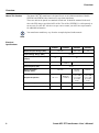
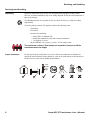
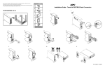
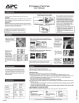
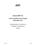
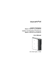
Smart-UPS® RT
Isolation Transformer
Models: SURT001 and SURT002
Isolation and Step-Down Transformer
Models: SURT003 and SURT004
User Manual
990-1673A, English, 11/2003
General Information
General Information
About APC
American Power Conversion (APC) is the leading manufacturer of state-of-the art
uninterruptible power supplies, power management software, and related equipment. APC
products protect hardware, software, and data from power disturbances in business and
government offices throughout the world.
Safety Information
Ensure that you read, understand and comply with the safety instructions and warnings
contained in the Safety Manual shipped with this product before installing, operating or
maintaining APC equipment.
Regulatory Agency
Approvals and Radio
Frequency Warnings
200, 208, 220, 230, 240 Models:
This is a Class A product. In a domestic environment this product may cause radio
interference, in which case, the user may be required to take corrective actions.
®
®
LISTED 42C2
E95463
LR 63938
N394
geprüfte
Sicherheit
ME 61
This equipment has been tested and found to comply with the limits for a Class A digital
device, pursuant to part 15 of the FCC Rules. These limits are designed to provide reasonable
protection against harmful interference when the equipment is operated in a commercial
environment. This equipment generates, uses, and can radiate radio frequency energy and, if
not installed and used in accordance with the instruction manual, may cause harmful
interference to radio communications. Operation of this equipment in a residential area is
likely to cause harmful interference. The user is responsible for correcting the interference.
BSMI
Smart-UPS RT Transformer—User’s Manual
3
General Information
Declaration of
Conformity
2003
EC Declaration of Conformity
We, the undersigned, declare under our sole responsibility that the equipment specified below conforms to the
following standards and directives:
Standards to Which Conformity Declared:
Application of Council Directives:
Type of Equipment:
Model Numbers:
Manufacturer's Name and Address:
Importer’s Name and Address:
Copyright and
Trademark
Information
4
EN62040-1-1, EN50091-1-1, IEC60950-1, EN 60950-1,
EN50091-2, EN55022, EN55024, EN61000-2-2, -3-2,
-3-3, -4-3, -4-5, -4-6, -4-8, -4-11
73/23EEC, 93/68/33C
89/336/EEC, 92/31/33C, 93/68/EEC, 91/157/EEC
Smart-UPS RT Transformer
SURT001, SURT002
American Power Conversion
132 Fairgrounds Road
West Kingston, Rhode Island, 02892, USA
-orAmerican Power Conversion (A. P. C.) b. v.
Ballybritt Business Park
Galway, Ireland
-orAmerican Power Conversion
Main Avenue, Peza
Rosario, Cavite, Philippines
-orAmerican Power Conversion
2nd Street, Peza, Cavite Economic Zone
Rosario, Cavite Philippines
-orAmerican Power Conversion
Lot 32 Phase 1 Carmelray Industrial Park
Canlubang, Calamba, Luguna Philippines
-orAPC (Suzhou) UPS Co., Ltd
No. 189 Suhong Road, China-Singapore
Suzhou Industrial Park
Suzhou 215021, Jiangsu, P.R.C
American Power Conversion (A. P. C.) b. v.
Ballybritt Business Park
Galway, Ireland
Place:
N. Billerica, MA U.S.
14 Aug 03
Stephen Lee, Regulatory Compliance Engineer
Place:
Galway, Ireland
14 Aug 03
Ray S. Ballard, Managing Director, Europe
Phone: 353 917 02000 Fax: 353 9175 6909
Entire contents copyright © 2003 by American Power Conversion Corporation. All rights
reserved. Reproduction in whole or in part without permission is prohibited.
APC®, Symmetra® Smart-UPS®, NetShelter® InfraStruXure® and PowerChute® are
registered trademarks of American Power Conversion Corporation. All other trademarks are
the property of their respective owners.
Smart-UPS RT Transformer—User’s Manual
General Information
Service
If the transformer requires service do not return it to the dealer. Instead, follow these steps:
1. Contact APC Customer Service through the APC web site, www.apc.com/support.
– Note the model number of the transformer, the serial number, and the date
purchased. If you call APC Customer Service, a technician will ask you to describe
the problem and try to solve it over the phone, if possible. If this is not possible, the
technician will issue a Returned Material Authorization Number (RMA#).
– If the transformer is under warranty, repairs are free. If not, there is a repair charge.
2. Pack the transformer in its original packaging. If the original packing is not available,
refer to the APC web site, www.apc.com/support, for information about obtaining a
new set.
– Pack the transformer properly to avoid damage in transit. Never use Styrofoam
beads for packaging. Damage sustained in transit is not covered under warranty.
3. Mark the RMA# on the outside of the package.
4. Return the transformer by insured, prepaid carrier to the address given to you by
Customer Service.
Limited Warranty
American Power Conversion (APC) warrants its products to be free from defects in materials
and workmanship for a period of two years from the date of purchase. Its obligation under
this warranty is limited to repairing or replacing, at its own sole option, any such defective
products. To obtain service under warranty you must obtain a Returned Material
Authorization (RMA) number from customer support. Products must be returned with
transportation charges prepaid and must be accompanied by a brief description of the problem
encountered and proof of date and place of purchase. This warranty does not apply to
equipment that has been damaged by accident, negligence, or misapplication or has been
altered or modified in any way. This warranty applies only to the original purchaser who must
have properly registered the product within 10 days of purchase.
EXCEPT AS PROVIDED HEREIN, AMERICAN POWER CONVERSION MAKES NO
WARRANTIES, EXPRESSED OR IMPLIED, INCLUDING WARRANTIES OF
MERCHANTABILITY AND FITNESS FOR A PARTICULAR PURPOSE. Some states do
not permit limitation or exclusion of implied warranties; therefore, the aforesaid limitation(s)
or exclusion(s) may not apply to the purchaser.
EXCEPT AS PROVIDED ABOVE, IN NO EVENT WILL APC BE LIABLE FOR DIRECT,
INDIRECT, SPECIAL, INCIDENTAL, OR CONSEQUENTIAL DAMAGES ARISING
OUT OF THE USE OF THIS PRODUCT, EVEN IF ADVISED OF THE POSSIBILITY OF
SUCH DAMAGE. Specifically, APC is not liable for any costs, such as lost profits or
revenue, loss of equipment, loss of use of equipment, loss of software, loss of data, costs of
substitutes, claims by third parties, or otherwise.
Contacting APC
In the USA: Refer to the APC web site, www.apc.com/support.
Outside the USA: Refer to the APC web site, www.apc.com. Select the appropriate country
from the country selection field. Select the Support tab at the top of the web page.
User Manual
The User Manual and Safety Guide are accessible on the supplied User Manual CD and on
the APC web site, www.apc.com.
Smart-UPS RT Transformer—User’s Manual
5
Overview
Overview
The Smart-UPS® RT transformer is designed for use as an isolation transformer. Models
SURT003 and SURT004 also function as a step-down transformer.
About This Product
The tower unit can be placed in a standard 19-inch rack. It should be mounted in the rack
above the UPS using a specialized APC rail kit. The rail kit, SURTRK2, is sold separately as
an accessory. See the APC website www.apc.com or contact your APC sales representative
for additional information.
Your transformer model may vary from the examples depicted in this manual.
Note
Electrical
Specifications
SURT001
SURT002
220–240
Nominal Input Voltage (VAC)
Input Connection
16
208 or 240
200
30
IEC C20
Hardwire
(10 AWG)
3 ft. cord with L6-30P
45–65
Line Frequency (Hz)
220-240/
208/120
200/100
IEC C19
Hardwire
(10 AWG)
(2) L6-20R
(1) L6-30R
(1) L14-30R
(8) 5-20R
T-slot
(1) L6-20R
(1) L6-30R
(2) L5-20R
(8) 5-20R
T-slot
Maximum Output Power (VA)
3000
5000
4800
4600
Maximum Output Power (Watt)
3000
5000
4800
4600
Nominal Output
Voltage (VAC)
Output Receptacles
6
SURT004
170–280
Input Voltage Range (VAC)
Input Service Maximum Current
(Amps)
SURT003
220–240
Smart-UPS RT Transformer—User’s Manual
Overview
Wiring
Diagrams
Models: SURT001 and SURT002
Bypass
Utility
Souce
AC In
C20 or
Hardwire
Transformer
P
D
U
UPS
UPS
C19 or
Hardwire
P
D
U
Inverter
AC Output to
Load Equipment
Models: SURT003 and SURT004
Bypass
Utility
Souce
AC In
UPS
UPS
Inverter
P
D
U
Transformer
3 ft Cable
L6-30 Plug
P
D
U
AC Output to
Load Equipment
Typical System Configuration
Utility Voltage
UPS Output
Input Voltage
Selection Switch
Position
Transformer
Output Voltage
SURT001
230
230
N/A
230
SURT002
230
230
N/A
230
SURT003
208
208
208
240/208/120
Model
SURT003
240
240
240
240/208/120
SURT003
220
220
240
220/208/110
SURT004
200
200
N/A
200/100
Smart-UPS RT Transformer—User’s Manual
7
Receiving and Handling
Receiving and Handling
Unpacking
Inspect the transformer upon receipt. APC designed robust packaging for this product.
However, accidents and damage may occur during shipment. Notify the carrier and dealer if
there is any damage.
The shipping materials are recyclable. Please save them for later use, or dispose of them
appropriately.
Check the package contents. The package contains the following items:
– Transformer
– Front Bezel
– Literature kit containing:
• Smart-UPS User Manuals CD
• Product documentation, safety and warranty information
• 3 tie brackets, 2 screws
– Model SURT001: one 16-Amp, 1-meter, C19/C20 jumper cable
The transformer is heavy. Three people are required to transport or lift the
transformer due to its weight.
Proper Ventilation
Do not operate the unit where there is excessive dust or the temperature or humidity are
outside the specified limits. Ensure that the air vents on the front and rear of the unit are not
blocked. See www.apc.com for additional information.
40°C
104°F
8
1
in.
1
in.
2.5
cm
2.5
cm
0°C
32°F
95%
0%
Smart-UPS RT Transformer—User’s Manual
Installation
Installation
Installing the Tower
Transformer
Follows these instructions when installing the transformer with a new or existing
Smart-UPS® RT UPS.
• The transformer must be installed to the LEFT of the UPS when facing the
FRONT of the units.
Note
• If your configuration includes the optional bypass panel, ensure that the bypass
panel is installed to the LEFT of the transformer when facing the FRONT of the
units. Refer to the bypass panel manual for installation instructions.
• Secure the transformer to the UPS using the provided tie brackets.
1. Move the transformer to the installation site. See “Unpacking” on page 8 for
additional information.
2. Remove the covers on the transformer and UPS as shown.
3. Remove the 2 screws at the top and bottom of the UPS and transformer .
Smart-UPS RT Transformer—User’s Manual
9
Installation
4. Secure the transformer to the UPS.
a. Locate the 2 screws and 3 tie brackets from the
literature kit.
b. Secure the appropriate tie bracket with screws to
the top of the units .
c. Reuse the screws removed in step 3 to secure tie
brackets at the top and bottom of the units.
5. Reuse the screws removed in step 2 to secure the
covers to the UPS and transformer .
6. Install the transformer bezel to the front of the
unit.
7. See the “Connection and Startup Instructions,”
beginning on page 10 to complete the installation.
Connection and
Startup Instructions
Model SURT001
1
1. Connect the transformer input (C20) connection to the utility source.
2. Connect the UPS to the transformer output (C19)
connection using the provided jumper cable.
3. Ensure that the input circuit breaker is turned ON.
10
Smart-UPS RT Transformer—User’s Manual
Installation
Model SURT002
• Verify that all branch circuit (mains) are de-energized and locked out before
installing cables or making connections.
Caution
• Wiring by a licensed electrician is required.
• Adhere to all national and local electrical codes.
Note
• Use 10-AWG wires.
1. Turn OFF the utility circuit breaker.
2. Turn OFF the UPS.
3. Ensure that the transformer input circuit breaker
is turned OFF.
4. Remove the wiring cover to access the
terminal block.
5. Remove circular knockouts .
6. Locate the transformer input and output terminal connections.
– The utility circuit breaker is hardwired to the
transformer input connection terminals.
– The UPS is hardwired to the transformer
output connection terminals. See the UPS
manual for additional information.
7. Feed the input (utility) and output (UPS) cables through the transformer wiring cover .
a. Connect the input (utility) cables to the input
terminals.
b. Connect the output (UPS) cables to the
output terminals.
• The transformer requires a 230 VAC
single-phase input with a minimum
branch breaker rating of 25-amps.
c. Inspect the connections.
d. Secure the wiring cover to the transformer
with the provided screws.
8. Turn ON the utility circuit breaker.
9. Turn ON the transformer input circuit
breaker .
10.Turn ON the UPS.
Smart-UPS RT Transformer—User’s Manual
11
Installation
Models SURT003 and SURT004
SURT003
1. Ensure that the transformer input cord is
unplugged.
2. For Model SURT003:
a. Remove the voltage selection switch cover .
b. Set the input voltage selection switch to
match the utility voltage of 208 or 240 VAC.
See the table on page 7.
c. If 240V utility is used, program the UPS output
for 240V. See the UPS user manual.
d. Install the voltage selection switch cover .
Tower to Rack-mount
Conversion
Note
3. Plug applicable load equipment into the PDU
receptacles on the transformer.
4. Plug the transformer input cord into the
appropriate PDU receptacle on the rear of the UPS.
5. Ensure that the output circuit breakers are ON.
6. Ensure that the input circuit breaker is ON.
SURT004
This section contains information on how to install a tower transformer in a 19-inch rack.
• The transformer must be installed directly above the UPS in the rack.
• If your configuration includes the optional bypass panel, ensure that the bypass
panel is installed above the transformer in the rack. Refer to the bypass panel
manual for installation instructions.
1. Install the transformer directly above the UPS in the rack. Refer to the Smart-UPS RT
Tower to Rack-mount Conversion Guide and the optional transformer rail kit.
2. See the “Connection and Startup Instructions,” beginning on page 10 to complete the
installation.
12
Smart-UPS RT Transformer—User’s Manual