1
EULA Terms
•
You have acquired a device ("DEVICE") that includes software licensed by DENSO CORPORATION from an affiliate of Microsoft
Corporation ("MS"). Those installed software products of MS origin, as well as associated media, printed materials, and "online" or
electronic documentation ("SOFTWARE") are protected by international intellectual property laws and treaties. Manufacturer, MS and
its suppliers (including Microsoft Corporation) own the title, copyright, and other intellectual property rights in the SOFTWARE. The
SOFTWARE is licensed, not sold. All rights reserved.
•
This EULA is valid and grants the end-user rights ONLY if the SOFTWARE is genuine and a genuine Certificate of
Authenticity for the SOFTWARE is included. For more information on identifying whether your software is genuine, please see
http://www.microsoft.com/piracy/howtotell.
•
IF YOU DO NOT AGREE TO THIS END USER LICENSE AGREEMENT ("EULA"), DO NOT USE THE DEVICE OR COPY THE
SOFTWARE. INSTEAD, PROMPTLY CONTACT DENSO CORPORATION FOR INSTRUCTIONS ON RETURN OF THE UNUSED
DEVICE(S) FOR A REFUND. ANY USE OF THE SOFTWARE, INCLUDING BUT NOT LIMITED TO USE ON THE DEVICE,
WILL CONSTITUTE YOUR AGREEMENT TO THIS EULA (OR RATIFICATION OF ANY PREVIOUS CONSENT).
•
GRANT OF SOFTWARE LICENSE. This EULA grants you the following license:
You may use the SOFTWARE only on the DEVICE.
Restricted Functionality. You are licensed to use the SOFTWARE to provide only the limited functionality (specific tasks or
processes) for which the DEVICE has been designed and marketed by DENSO CORPORATION. This license specifically
prohibits any other use of the software programs or functions, or inclusion of additional software programs or functions that do
not directly support the limited functionality on the DEVICE. Notwithstanding the foregoing, you may install or enable on a
DEVICE, systems utilities, resource management or similar software solely for the purpose of administration, performance
enhancement and/or preventive maintenance of the DEVICE.
If you use the DEVICE to access or utilize the services or functionality of Microsoft Windows Server products (such as Microsoft
Windows Server 2003), or use the DEVICE to permit workstation or computing devices to access or utilize the services or
functionality of Microsoft Windows Server products, you may be required to obtain a Client Access License for the DEVICE
and/or each such workstation or computing device. Please refer to the end user license agreement for your Microsoft Windows
Server product for additional information.
NOT FAULT TOLERANT. THE SOFTWARE IS NOT FAULT TOLERANT. DENSO CORPORATION HAS
INDEPENDENTLY DETERMINED HOW TO USE THE SOFTWARE IN THE DEVICE, AND MS HAS RELIED UPON
DENSO CORPORATION TO CONDUCT SUFFICIENT TESTING TO DETERMINE THAT THE SOFTWARE IS
SUITABLE FOR SUCH USE.
NO WARRANTIES FOR THE SOFTWARE. THE SOFTWARE is provided "AS IS" and with all faults. THE ENTIRE RISK
AS TO SATISFACTORY QUALITY, PERFORMANCE, ACCURACY, AND EFFORT (INCLUDING LACK OF
NEGLIGENCE) IS WITH YOU. ALSO, THERE IS NO WARRANTY AGAINST INTERFERENCE WITH YOUR
ENJOYMENT OF THE SOFTWARE OR AGAINST INFRINGEMENT. IF YOU HAVE RECEIVED ANY WARRANTIES
REGARDING THE DEVICE OR THE SOFTWARE, THOSE WARRANTIES DO NOT ORIGINATE FROM, AND ARE NOT
BINDING ON, MS.
No Liability for Certain Damages. EXCEPT AS PROHIBITED BY LAW, MS SHALL HAVE NO LIABILITY FOR ANY
INDIRECT, SPECIAL, CONSEQUENTIAL OR INCIDENTAL DAMAGES ARISING FROM OR IN CONNECTION WITH
THE USE OR PERFORMANCE OF THE SOFTWARE. THIS LIMITATION SHALL APPLY EVEN IF ANY REMEDY
FAILS OF ITS ESSENTIAL PURPOSE. IN NO EVENT SHALL MS BE LIABLE FOR ANY AMOUNT IN EXCESS OF U.S.
TWO HUNDRED FIFTY DOLLARS (U.S.$250.00).
Restricted Uses. The SOFTWARE is not designed or intended for use or resale in hazardous environments requiring fail-safe
performance, such as in the operation of nuclear facilities, aircraft navigation or communication systems, air traffic control, or
other devices or systems in which a malfunction of the SOFTWARE would result in foreseeable risk of injury or death to the
operator of the device or system, or to others.
Limitations on Reverse Engineering, Decompilation, and Disassembly. You may not reverse engineer, decompile, or
disassemble the SOFTWARE, except and only to the extent that such activity is expressly permitted by applicable law
notwithstanding this limitation.
SOFTWARE as a Component of the DEVICE - Transfer. This license may not be shared, transferred to or used concurrently on
different computers. The SOFTWARE is licensed with the DEVICE as a single integrated product and may only be used with
the DEVICE. If the SOFTWARE is not accompanied by a DEVICE, you may not use the SOFTWARE. You may permanently
transfer all of your rights under this EULA only as part of a permanent sale or transfer of the DEVICE, provided you retain no
copies of the SOFTWARE. If the SOFTWARE is an upgrade, any transfer must also include all prior versions of the
SOFTWARE. This transfer must also include the Certificate of Authenticity label. The transfer may not be an indirect transfer,
such as a consignment. Prior to the transfer, the end user receiving the SOFTWARE must agree to all the EULA terms.
Consent to Use of Data. You agree that MS, Microsoft Corporation and their affiliates may collect and use technical information
gathered in any manner as part of product support services related to the SOFTWARE. MS, Microsoft Corporation and their
affiliates may use this information solely to improve their products or to provide customized services or technologies to you. MS,
Microsoft Corporation and their affiliates may disclose this information to others, but not in a form that personally identifies
you.
Internet Gaming/Update Features. If the SOFTWARE provides, and you choose to utilize, the Internet gaming or update
features within the SOFTWARE, it is necessary to use certain computer system, hardware, and software information to
implement the features. By using these features, you explicitly authorize MS, Microsoft Corporation and/or their designated
agent to use this information solely to improve their products or to provide customized services or technologies to you. MS or
Microsoft Corporation may disclose this information to others, but not in a form that personally identifies you.
Internet-Based Services Components. The SOFTWARE may contain components that enable and facilitate the use of certain
Internet-based services. You acknowledge and agree that MS, Microsoft Corporation or their affiliates may automatically check
the version of the SOFTWARE and/or its components that you are utilizing and may provide upgrades or supplements to the
SOFTWARE that may be automatically downloaded to your DEVICE. Microsoft Corporation or their affiliates do not use these
features to collect any information that will be used to identify you or contact you. For more information about these features,
please see the privacy statement at http://go.microsoft.com/fwlink/?LinkId=25243.
Links to Third Party Sites. You may link to third party sites through the use of the SOFTWARE. The third party sites are not
under the control of MS or Microsoft Corporation, and MS or Microsoft are not responsible for the contents of any third party
sites, any links contained in third party sites, or any changes or updates to third party sites. MS or Microsoft Corporation is not
responsible for webcasting or any other form of transmission received from any third party sites. MS or Microsoft Corporation
are providing these links to third party sites to you only as a convenience, and the inclusion of any link does not imply an
endorsement by MS or Microsoft Corporation of the third party site.
Notice Regarding Security. To help protect against breaches of security and malicious software, periodically back up your data
and system information, use security features such as firewalls, and install and use security updates.
No Rental/Commercial Hosting. You may not rent, lease, lend or provide commercial hosting services with the SOFTWARE to
others.
Separation of Components. The SOFTWARE is licensed as a single product. Its component parts may not be separated for use
on more than one computer.
Additional Software/Services. This EULA applies to updates, supplements, add-on components, product support services, or
Internet-based services components ("Supplemental Components"), of the SOFTWARE that you may obtain from DENSO
CORPORATION, MS, Microsoft Corporation or their subsidiaries after the date you obtain your initial copy of the SOFTWARE,
unless you accept updated terms or another agreement governs. If other terms are not provided along with such Supplemental
Components and the Supplemental Components are provided to you by MS, Microsoft Corporation or their subsidiaries then
you will be licensed by such entity under the same terms and conditions of this EULA, except that ( i ) MS, Microsoft
Corporation or their subsidiaries providing the Supplemental Components will be the licensor with respect to such
Supplemental Components in lieu of the DENSO CORPORATION for the purposes of the EULA, and ( ii ) TO THE
MAXIMUM EXTENT PERMITTED BY APPLICABLE LAW, THE SUPPLEMENTAL COMPONENTS AND ANY (IF ANY)
SUPPORT SERVICES RELATED TO THE SUPPLEMENTAL COMPONENTS ARE PROVIDED AS IS AND WITH ALL
FAULTS. ALL OTHER DISCLAIMERS, LIMITATION OF DAMAGES, AND SPECIAL PROVISIONS PROVIDED BELOW
AND/OR OTHERWISE WITH THE SOFTWARE SHALL APPLY TO SUCH SUPPLEMENTAL COMPONENTS. MS,
Microsoft Corporation or their subsidiaries reserve the right to discontinue any Internet-based services provided to you or made
available to you through the use of the SOFTWARE.
Recovery Media. If SOFTWARE is provided by DENSO CORPORATION on separate media and labeled "Recovery Media"
you may use the Recovery Media solely to restore or reinstall the SOFTWARE originally installed on the DEVICE.
Backup Copy. You may make one (1) backup copy of the SOFTWARE. You may use this backup copy solely for your archival
purposes and to reinstall the SOFTWARE on the DEVICE. Except as expressly provided in this EULA or by local law, you may
not otherwise make copies of the SOFTWARE, including the printed materials accompanying the SOFTWARE. You may not
loan, rent, lend or otherwise transfer the backup copy to another user.
End User Proof of License. If you acquired the SOFTWARE on a DEVICE, or on a compact disc or other media, a genuine
Microsoft "Proof of License"/Certificate of Authenticity label with a genuine copy of the SOFTWARE identifies a licensed copy of
the SOFTWARE. To be valid, the label must be affixed to the DEVICE, or appear on DENSO CORPORATION's software
packaging. If you receive the label separately other than from DENSO CORPORATION, it is invalid. You should keep the label
on the DEVICE or packaging to prove that you are licensed to use the SOFTWARE.
Product Support. Product support for the SOFTWARE is not provided by MS, Microsoft Corporation, or their affiliates or
subsidiaries. For product support, please refer to DENSO CORPORATION support number provided in the documentation for
the DEVICE. Should you have any questions concerning this EULA, or if you desire to contact DENSO CORPORATION for
any other reason, please refer to the address provided in the documentation for the DEVICE.
Termination. Without prejudice to any other rights, DENSO CORPORATION may terminate this EULA if you fail to comply
with the terms and conditions of this EULA. In such event, you must destroy all copies of the SOFTWARE and all of its
component parts.
EXPORT RESTRICTIONS. You acknowledge that SOFTWARE is subject to U.S. and European Union export jurisdiction. You
agree to comply with all applicable international and national laws that apply to the SOFTWARE, including the U.S. Export
Administration Regulations, as well as end-user, end-use and destination restrictions issued by U.S. and other governments.
For additional information see http://www.microsoft.com/exporting/.
Preface
Preface
Thank you for purchasing this Intelligent Tester II.
Read this document carefully so that you can use this tester correctly and safely.
-i-
For safe usage
For safe usage
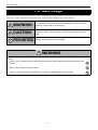
This document uses symbols for warnings, cautions, and prohibitions. These symbols and their meanings are as follows. Please
make sure you fully understand the meanings of these symbols before reading the rest of this document.
WARNING
This indicates an item for which incorrect handling can result in a major
accident involving death or serious injury.
CAUTION
Indicates an item for which incorrect handling can lead to injury or damage
to property. Under certain conditions, more serious consequences may
result.
PROHIBITIED
Indicates a prohibited method of handling.
WARNING
Always observe the following rules. Failure to do so can result in heat generation, fire, blowout, or electrical
shock.
Do not use or charge this device with anything other than the AC adapter specifically designed for this
tester.
Do not disassemble or alter this tester.
Do not connect this tester to anything with a voltage exceeding the ratings of this tester.
- ii -
For safe usage
CAUTION
Do not leave this tester in any location subject to excessive heat for example in direct sunlight or inside a
car on a sunny day.
Do no touch any metal parts when connecting the test leads to the measurement position, even when
within the ratings range.
Do not work anywhere that water could come in contact with the equipment.
Do not drop this tester or subject it to a strong impact.
This could cause the liquid crystal leak from inside the tester.
A rash may result if the liquid crystal comes into contact with the skin.
If this happens, wash the skin with plenty of running water, then seek medical attention.
Block the wheels of the vehicle with chocks before carrying out work such as connecting the tester cable.
Failure to do so could result in an accident.
Do not pass the cable for this tester over the engine compartment while the engine is running.
An accident may result in cable, test lead, or clothing becomes caught in a belt or pulley.
When working anywhere not be easily visible, for example under the vehicle, always remove the key from
the ignition to ensure the vehicle cannot is not moved.
Failure to do so could result in an accident.
Do not work connect the tester cables etc. while the vehicle is running.
Doing so could result in an accident.
When working near the engine compartment, be careful of the engine and other high-temperature parts.
High-temperature parts can cause burns.
Trademarks
Microsoft and Windows CE are trademarks or registered trademarks of the Microsoft Corp. of the United States in the
United States and other countries.
CompactFlashTM is a registered trademark of the SanDisk Corp. of the United States and is licensed to the CFA
(CompactFlashTM Association).
- iii -
Table of contents
Table of contents
1
Before Use
Product Configuration ...................................................................................................................................... 2
Standard Components .................................................................................................................................... 2
AC / DC Power Supply.................................................................................................................................... 4
Optional Accessories ...................................................................................................................................... 5
Oscilloscope Accessories ............................................................................................................................... 5
Confirmation of the manufacturing model ..................................................................................................... 6
Names of the Parts ........................................................................................................................................... 8
Charging .......................................................................................................................................................... 11
Internal Battery.............................................................................................................................................. 13
2
Connection ...................................................................................................................................................... 14
Connecting to the Vehicle ............................................................................................................................. 14
Connecting to a PC....................................................................................................................................... 15
Inserting a CF Card....................................................................................................................................... 16
Connecting the Oscilloscope Cartridge......................................................................................................... 17
Connecting the Probes ................................................................................................................................. 18
Basic Operations
Starting and Ending ........................................................................................................................................ 21
Starting.......................................................................................................................................................... 21
Ending........................................................................................................................................................... 23
Screen Configuration ..................................................................................................................................... 24
Main Menu Buttons ....................................................................................................................................... 24
Title Bar......................................................................................................................................................... 25
Menu Bar ...................................................................................................................................................... 26
Basic Operations ............................................................................................................................................ 29
Display Operation ......................................................................................................................................... 29
Main Unit Operation ...................................................................................................................................... 31
3
In Case of Error ............................................................................................................................................... 32
Communication Errors .................................................................................................................................. 32
System Errors ............................................................................................................................................... 33
Screen Lock Errors ....................................................................................................................................... 33
Default Settings
Tool Option Function...................................................................................................................................... 35
Supplementary Functions (Set Up)............................................................................................................... 36
Clock Functions (Date/Time) ........................................................................................................................ 37
Language Selection Function (Language Select) ......................................................................................... 37
Unit Conversion Function (Unit Conversion)................................................................................................. 38
Brand Selection Function (Brand Select)...................................................................................................... 38
Version Display Function (Version Information)............................................................................................ 39
Touch Panel Compensation Function (Screen Configuration)...................................................................... 40
Data Storage Setting Function (Memory Select) .......................................................................................... 41
Button Setting Functions (Button Configuration)........................................................................................... 41
- iv -
Table of contents
4
Diagnostics Functions
System Selection ............................................................................................................................................ 43
DTC Check ....................................................................................................................................................... 46
DTC Data Display ......................................................................................................................................... 46
DTC Data Storage ........................................................................................................................................ 47
DTC Data Clear ............................................................................................................................................ 49
Freeze Frame Data Display .......................................................................................................................... 50
Data List ........................................................................................................................................................... 54
Data List Display ........................................................................................................................................... 54
Display Switching.......................................................................................................................................... 56
Snapshots ..................................................................................................................................................... 65
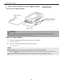
How to use the optional accessory Trigger Snapshot................................................................................... 67
Data List Manager......................................................................................................................................... 71
Active Test....................................................................................................................................................... 73
Active Test Item Selection ............................................................................................................................ 73
Active Test Execution ................................................................................................................................... 74
5
Utilities ............................................................................................................................................................. 76
Explanation of Button Operations ................................................................................................................. 77
Explanation of ECU Reprogramming Functions ........................................................................................... 78
Calibration File Manager............................................................................................................................... 79
Saved Data Playback Functions
DTC Playback .................................................................................................................................................. 82
6
Snapshot Playback ......................................................................................................................................... 84
Playback With Snapshot Flag Set................................................................................................................. 86
Measurement Functions
Voltage Measurement Functions................................................................................................................... 89
Measurement Function Selection Menu ....................................................................................................... 89
Voltage Display ............................................................................................................................................. 90
Waveform Display......................................................................................................................................... 91
Calibration..................................................................................................................................................... 93
Screen Image Save/Playback/Delete ........................................................................................................... 94
7
Oscilloscope Functions ................................................................................................................................. 98
Oscilloscope Measurement Menu................................................................................................................. 98
Waveform Display......................................................................................................................................... 99
Trigger Menu............................................................................................................................................... 101
Screen Image Save/Playback/Delete ......................................................................................................... 105
Handling
Handling Precautions ................................................................................................................................... 113
Disposal ......................................................................................................................................................... 113
8
Battery Replacement .................................................................................................................................... 114
Product Specifications
Intelligent Tester II Specifications ............................................................................................................... 120
Voltage Measurement Function Specifications ......................................................................................... 121
9
Oscilloscope Function Specifications ........................................................................................................ 121
After-Service
-v-
1 Before Use
1 Before Use
1
Before Use
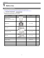
Product Configuration
Check that you have all the following standard components before using this tester.
For information on the Optional Accessories and Oscilloscope Accessories, reference Page 5.
Standard Components
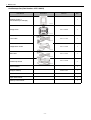
Standard Set (Part Number: 95171-00791)
Part Name
Illustration
Part No.
Q'ty
-
1
95171-20820
1
95171-11110
1
95171-10120
1
95171-10110
1
-
1
95009-13227
1
Quick Reference Manual
-
1
Repair Order Sheet
-
1
Warranty Terms Sheet
-
1
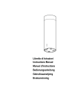
Intelligent Tester II
(without oscilloscope cartridge)
T00009E
Storage Case
T01075E
DLC3 Cable
T00012E
Voltage Meter Probe
T00013E
USB Cable
T00014E
Screen Overlay
CD-ROM (Operator’s Manual,
Intelligent Viewer)
-2-
1 Before Use
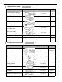
Oscilloscope Set (Part Number: 95171-00801)
Part Name
Illustration
Part No.
Q'ty
-
1
95171-20820
1
95171-11110
1
95171-10120
1
95171-10110
1
95171-10500
2
-
1
95009-13227
1
Quick Reference Manual
-
1
Repair Order Sheet
-
1
Warranty Terms Sheet
-
1
Intelligent Tester II
(with oscilloscope cartridge)
T00009E
Storage Case
T01075E
DLC3 Cable
T00012E
Voltage Meter Probe
T00013E
USB Cable
T00014E
Oscilloscope Probe
T00021E
Screen Overlay
CD-ROM (Operator’s Manual,
Intelligent Viewer)
-3-
1 Before Use
AC / DC Power Supply
Part Name
Illustration
DENSO
Part No.
Country
Q'ty
95171-11650
Hong Kong
Malaysia
England
Singapore
1
95171-11660
South Africa
1
95171-11670
Argentina
1
95171-11680
Israel
1
95171-11750
Australia
New Zealand
1
95171-10321
U.S.A
Canada
1
95171-11260
China
1
95171-11440
Taiwan
1
95171-11640
Korea
1
95171-11690
Other countries
1
T00263E
T00264E
T00265E
T00266E
AC / DC Power Supply
T00265E
T00267E
T00267E
T00267E
T00266E
T00266E
NOTE
Some of power plugs are same shape, but they are different by regulations in each country.
When you purchase AC/DC Power Supply, please refer the end user country in the above listand choose
carefully the appropriate product number.
-4-
1 Before Use
Optional Accessories
Part Name
Illustration
Part No.
Q'ty
95171-10140
1
95171-10150
1
95171-10130
1
95171-10200
1
95171-10210
1
Screen Overlay
95171-10220
5
Replacement Battery
95171-10341
1
Storage Card (128MB)
95171-11121
1
DC Power Cable for Cigarette
Lighter Socket
T00022E
Trigger Snapshot
T00023E
RS-232C Cable
T00024E
Battery Power Cable
(DLC3 Cable Type)
T00025E
Battery Power Cable
(Cigarette Lighter Type)
T00026E
Oscilloscope Accessories
Part Name
Illustration
Oscilloscope Set
Part No.
Q'ty
95171-00070
Cartridge(1),
Probe(2).
95171-10240
1
95171-10500
1
95171-10170
Red(1),
black(1).
95171-10180
Red(1),
black(1).
95171-10190
Red(1),
black(1).
T00027E
Oscilloscope Cartridge
T00028E
Oscilloscope Probe
T00021E
Attachment of Oscilloscope Probe
(Clip Set)
T00030E
Attachment of Oscilloscope Probe
(IC Clip Set)
T00031E
Attachment of Oscilloscope Probe
(Needle Set)
T00032E
-5-
1 Before Use
Confirmation of the manufacturing model
There are two separate types of manufacturing models for the Intelligent Tester II.
Depending on the manufacturing model, there are certain features that differ.
In regards to the difference in features between manufacturing models, please refer to "Display Contrast".
Reference: Page 36 Display Contrast (Chapter 3. Default Settings/Tool Option Function/Supplementary Functions (Set Up))
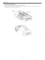
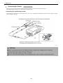
The following will explain how to confirm the manufacturing model.
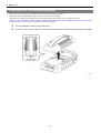
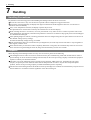
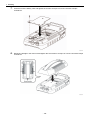
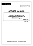
1.
Turn the Intelligent Tester II power switch OFF.
2.
Loosen the five screws on the rear of the main unit with a Philips screwdriver and take out the cartridge.
T00248E
-6-
1 Before Use
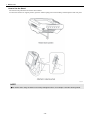
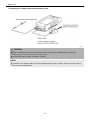
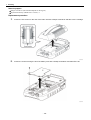
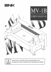
3.
Visually check the serial number label attached to the rear side of the Intelligent Tester II main unit and
verify the manufacturing model.
Serial number label
T01023E
DN-IT2-001: Intelligent Tester II manufactured on or before August 2008
DN-IT2-002: Intelligent Tester II manufactured on and after September 2008
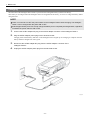
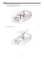
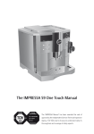
4.
Mount the cartridge in the main unit and tighten the five screws to a torque of 0.5±0.1Nm with a Philips
screwdriver.
T00255E
CAUTION
When connecting the cartridge with the built-in to oscilloscope to the main unit, carefully check the
configuration of the connector and gently insert the cartridge straight in.
Inserting the cartridge at a slant can break the connector pins.
Be careful not to touch the connector section of the main unit or the cartridge with your hands.
-7-
1 Before Use
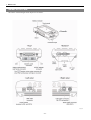
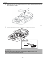
Names of the Parts
The names of the Intelligent Tester II parts are as follows.
T00033E
-8-
1 Before Use
How to Use the Holder Band
Slip your hand between the holder band and the Intelligent Tester II.
The length of the holder band can be adjusted using the velcro strap. If the holder band is too loose, adjust it so that the
Intelligent Tester II is held securely to your hand.
T00034E
-9-
1 Before Use
How to Use the Stand
The stand can be pulled out and used as shown below.
To return the stand to its original position, open the stand coupling section horizontally, and then push it back into place.
T00035E
NOTE
Be careful when using the stand on an easily damaged surface, for example a wooden steering wheel.
- 10 -
1 Before Use
Charging
The main unit of the Intelligent Tester II has a special internal rechargeable battery (lithium ion battery).
This battery is not charged when the Intelligent Tester II is shipped from the factory, so be sure to charge the battery before
using the tester.
NOTE
There is no need to turn OFF the power switch on the Intelligent Tester II while charging. The Intelligent
Tester II can be charged with the power ON or OFF.
It takes approximately five hours to fully charge the battery from a completely discharged state, regardless
of whether the power switch is ON or OFF.
1.
Connect the AC/DC adapter DC plug to the AC/DC adapter connector of the Intelligent Tester II.
2.
Plug the AC/DC adapter power plug into an electrical socket.
Charging starts and the battery indicator on the Intelligent Tester II lights up red. Charging is complete when the
battery indicator changes from red to green.
3.
Disconnect the AC/DC adapter DC plug from the AC/DC adapter connector of the
Intelligent Tester II.
4.
Unplug the AC/DC adapter power plug from the electrical socket.
T00036E
- 11 -
1 Before Use
CAUTION
Do not use devices other than the optional AC/DC adapter when charging the battery of the Intelligent
Tester II.
Using other adapters may prevent battery charging, and cause heating of and damage to the charger.
Do not leave the AC/DC adapter plugged into the electrical socket after charging is complete.
Dust can build up between the socket and the plug and cause tracking and fire.
If the battery is charged while outside the usage temperature range, the battery indicator flashes.
Continued charging in this condition could damage the equipment, so discontinue charging.
Do not connect the AC/DC adapter to the Intelligent Tester II, when using the oscilloscope function.
NOTE
The Intelligent Tester II can be connected to the vehicle with the datalink cable to run off the vehicle
battery when the tester internal battery is not charged.
In this state, the Intelligent Tester II internal battery will charge using the vehicle power, so take care not to
run down the vehicle battery.
When using the Intelligent Tester II without connecting it to the vehicle (for example when using it as an
oscilloscope), monitor the amount of power remaining in the battery and charge it with the AC/DC adapter
when it runs low.
The onboard/offboard check screen can be used to check the amount of power remaining in the battery.
Reference: Page 25 Battery icon (Chapter 2. Basic Operations/Screen Configuration/Title Bar)
It is normal for the main unit of the Intelligent Tester II to heat up during charging.
The Intelligent Tester II may be left connected to the AC/DC adapter when the charging is complete.
- 12 -
1 Before Use
Internal Battery
When the Intelligent Tester II is not connected to the vehicle, such as with the datalink cable or the external power cable,
the Intelligent Tester II is powered by its internal battery.
When the Intelligent Tester II is run on its internal battery, a fully charged battery will last approximately 80 minutes if
there is an oscilloscope cartridge or approximately one hour if there is not.
You can check the amount of power remaining in the battery with the onboard/offboard check screen.
Reference: Page 25 Battery icon (Chapter 2. Basic Operations/Screen Configuration/Title Bar)
The internal battery is a consumable part. When the time that a fully charged battery can be used becomes extremely short,
replace the internal battery.
Replace the internal battery with a new internal battery.
The Intelligent Tester II uses a specially made internal battery. When it becomes necessary to replace the internal battery,
please purchase a replacement battery and install it according to the replacement instructions.
Reference: Page 114 Battery Replacement (Chapter 7. Handling)
- 13 -
1 Before Use
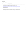
Connection
This section explains how to connect the tester to a vehicle or PC, how to mount a CF card, and how to connect the probes.
Connecting to the Vehicle
Use the datalink cable to connect the Intelligent Tester II to the vehicle.
Check the position of the vehicle-side datalink connector (DLC 3) in the vehicle repair manual.
T00037E
CAUTION
When connecting the datalink cable to the Intelligent Tester II and the vehicle side datalink connector
(DLC 3), gently insert it straight into the connector.
Inserting the cable at a slant can break the connector pins.
When connecting the data link cable to the Intelligent Tester II, make sure the connector is in the right
direction.
(If the data link cable connector has a
mark, it should be facing upwards.)
If you connect it the wrong way up or insert it at an angle, there is a risk of damaging the connector terminal and
causing a malfunction of the vehicle or Intelligent Tester II.
NOTE
The carrying case can remain on even when the data link cable is connected to the
Intelligent Tester II. It is recommended that you keep them connected all the time.
- 14 -
1 Before Use
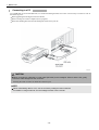
Connecting to a PC
Use a USB cable or serial cable (RS-232C) to connect the Intelligent Tester II to a PC. It is necessary to connect to a PC in
the following cases:
When upgrading the Intelligent Tester II software;
When rewriting the vehicle computer (ECU) program;
When downloading data stored in the Intelligent Tester II into your PC.
T00038E
CAUTION
When connecting a USB cable or serial cable (RS-232C) to the Intelligent Tester II and the PC, gently
insert the cable straight into the connector.
Inserting the cable at a slant can break the connector pins.
NOTE
When downloading data to a PC, use the accessory Intelligent Viewer software.
For details on usage methods, see the Intelligent Viewer user's manual.
- 15 -
1 Before Use
Inserting a CF Card
The Intelligent Tester II can use CF (CompactFlashTM) cards.
CAUTION
Please use the recommended CF card (DENSO Supply No. 95171-11121).
We cannot guarantee proper operation if a different CF card is used.
The methods for inserting/removing CF cards are as follows.
Inserting a CF card
Gently insert the CF card with the larger indentation (notch) facing to the left side.
When the CF card is fully inserted and set correctly, the CF card eject button is click out.
Removing a CF card
Press the CF card eject button.
The CF card will eject slightly, so gently pull it out the rest of the way.
T00039E
CAUTION
Do not insert anything but a CF card in this card slot.
Do not pull out a CF card when power is on.
- 16 -
1 Before Use
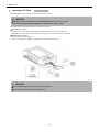
Connecting the Oscilloscope Cartridge
If you purchased the optional cartridge with the built-in oscilloscope, it is necessary to replace the standard cartridge with
this cartridge.
Loosen the five screws securing the standard cartridge and remove the cartridge.
Replace the standard cartridge with the built-in oscilloscope cartridge, and secure it in place by tightening the five screws
to a torque of 0.5±0.1 Nm.
T00040E
CAUTION
Always make sure the power to the Intelligent Tester II is OFF before replacing the cartridge.
When connecting the cartridge with the built-in to oscilloscope to the main unit, carefully check the
configuration of the connector and gently insert the cartridge straight in.
Inserting the cartridge at a slant can break the connector pins.
Be careful not to touch the connector section of the main unit or the cartridge with your hands.
- 17 -
1 Before Use
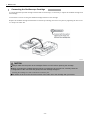
Connecting the Probes
There are two types of probe, the voltage measurement tester probe and the oscilloscope probe.
The oscilloscope probes are an accessory for the oscilloscope.
Connecting the oscilloscope probes
The probe tip is secured to the oscilloscope probe with a screw, regardless of whether the probe is an IC clip type, Needle
type, or alligator clip type.
T00041E
CAUTION
When connecting the probe to the Intelligent Tester II, gently insert it straight into the connector.
Inserting the probe at a slant can break the connector pins.
The tip of the probe is sharp, so handle it carefully.
Do not connect the AC/DC adapter to the Intelligent Tester II, when using the oscilloscope function.
- 18 -
1 Before Use
Connecting the voltage measurement tester probe
T00042E
CAUTION
When connecting the probe to the Intelligent Tester II, gently insert it straight into the connector.
Inserting the probe at a slant can break the connector pins.
The tip of the probe is sharp, so handle it carefully.
NOTE
In addition to the datalink cable, the optional cigarette lighter cable or battery cable can also be used to
ensure correct measurement.
- 19 -
2 Basic Operations
2 Basic Operations
2
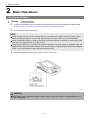
Basic Operations
Starting and Ending
Starting
1.
Connect the Intelligent Tester II and vehicle side datalink connectors (DLC3) with the datalink cable.
Reference: Page 14 Connecting to the Vehicle (Chapter 1. Before Use/Connection)
2.
Turn the vehicle ignition switch ON.
NOTE
Communication with the vehicle computer (ECU) is not possible if the ignition switch is at OFF or ACC.
When the Intelligent Tester II is turned ON, always switch the ignition switch ON or start the engine.
When the Intelligent Tester II is used as measurement function (voltage measurement, oscilloscope), it will
work even if the ignition switch is at OFF or ACC.
If the Intelligent Tester II is connected to the vehicle’s diagnostic connector (DLC3) by a datalink cable and
supplied with power via an AC/DC adapter or DC power cable for a cigarette lighter socket, the Intelligent
Tester II can be operated even with its power switch turned off.
3.
Press the Intelligent Tester II power switch to turn the power ON.
T00043E
CAUTION
During startup, never switch the Intelligent Tester II power switch OFF until the onboard/offboard check
screen is displayed.
- 21 -
2 Basic Operations
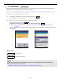
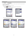
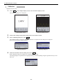
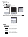
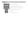
After the opening screen is displayed, the display automatically switches to the onboard/offboard check screen.
T00044E
T
T00045E
Toyota opening screen
Lexus opening screen
T00046E
Onboard/offboard check screen
NOTE
There are two opening screens, one for Toyota and one for Lexus. These are selected using the brand
select function. The factory setting is the Toyota opening screen.
Reference: Page 38 Brand Selection Function (Brand Select) (Chapter 3. Default Settings/Tool Option Function)
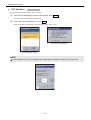
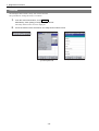
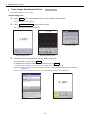
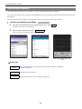
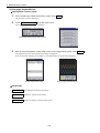
4.
When using the Intelligent Tester II as the OBD function, touch Auto or Manual on the onboard/
offboard screen.
The system select screen is displayed.
T00048E
T00047E
System select screen
Onboard/offboard check screen
NOTE
To execute the OBD function, choose whether the vehicle is to be selected automatically or manually.
Reference: Page 43 Automatic Vehicle Selection (Chapter 4. Diagnostics Functions/System Selection)
Reference: Page 44 Manual Vehicle Selection (Chapter 4. Diagnostics Functions/System Selection)
When using Voltage meter or another measurement function, select that function from the [Utility] menu.
- 22 -
2 Basic Operations
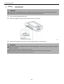
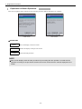
Ending
CAUTION
If the power to the Intelligent Tester II is switched OFF during an active test, the actuator may remain in
the drive state. Always end the active test before switching the power OFF.
1.
Turn the vehicle ignition switch OFF.
2.
Press the Intelligent Tester II power switch to turn the power OFF.
T00049E
3.
Disconnect the datalink cable from the vehicle side datalink connector (DLC3).
CAUTION
When disconnecting the datalink cable from vehicle side datalink connector (DLC 3), gently pull it straight
out of the connector.
Pulling the cable at a slant can break the connector pins.
When pulling the cable out, hold it by the connector section, and never by the cord section.
Pulling on the cord section can break the lines in the cable.
- 23 -
2 Basic Operations
Screen Configuration
The screen configuration for the Intelligent Tester II is as follows.
Menu Bar
Title Bar
Infomation display area
Function buttons
Main Menu Buttons
Screen Configuration
T00050E
NOTE
The Intelligent Tester II display is a touch panel, so use your fingers to operate it.
When a menu bar or button item is displayed in gray, this indicates that the item is disabled.
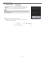
Main Menu Buttons
The main menu buttons are composed of frequently used functions.
These functions can be selected from the menu bars, but the main menu buttons enable these functions to be started at one
touch.
Main Menu Buttons
T00051E
ACTIVE KEY
DTC
Data List
View
Active Test
Utility
Starts the DTC check. Freeze frame data can also be checked with a DTC check.
Starts the data list. Snapshots can also be recorded with the data list.
Switches the data list display format.
Starts an active test.
Starts the utility.
- 24 -
2 Basic Operations
Title Bar
The title bar displays the ECU name and function names. Icons displaying the power status and communications status are
also shown at the right end.
The icon display at the right end of the title bar varies according to the connection between the Intelligent Tester II and the
vehicle computer (ECU).
Battery icon
T00052E
Connector icon
T00053E
Battery icon
This icon is displayed when the Intelligent Tester II and the vehicle computer (ECU) are not connected, to show that the
Intelligent Tester II is running on its internal battery. The battery icon also functions as an indicator showing the charge
level (remaining power) for the internal battery.
Connector icon
This icon is displayed when the Intelligent Tester II and the vehicle computer (ECU) are correctly connected, to show that
the Intelligent Tester II is running on vehicle power. The connector icon also functions as an indicator by showing the
communications status with its color.
When communication starts, the connector icon changes color according to the communication speed: low speed (green),
medium speed (yellow) and high speed (red). The communication speed is determined by the vehicle computer (ECU).
- 25 -
2 Basic Operations
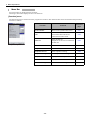
Menu Bar
Five menu titles are displayed in the menu bar.
Touching a menu titles displays the list of its functions.
[Function] menu
The [Function] menu is used to select the program for execution. The functions that can be selected from the [Function]
menu are as follows.
Function
T00054E
[Function] menu
Contents
Reference
page
System Select
Moves to the system select screen.
P.43
DTC
Starts the DTC check.
Freeze frame data can also be
checked with a DTC check.
P.46
Data List
Starts the data list.
Snapshots can also be recorded with
the data list.
P.54
Active Test
Starts an active test.
P.73
Utility
Starts the utility.
P.76
Snapshot Record
Starts snapshot recording.
P.65
Snapshot Configuration Starts snapshot detail setting.
P.68
Snapshot Review
Displays a saved snapshot data file.
P.84
Saved Data Review
Displays a saved DTC data file.
P.82
Data List Manager
Starts the data list manager.
P.71
- 26 -
2 Basic Operations
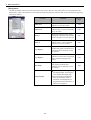
[View] menu
The data list display form can be selected from the [View] menu. However, the [View] menu is only enabled when the
[Data List] or [Active Test] function is selected from the [Function] menu. Functions that can be selected from the [View]
menu are as follows.
Function
[View] menu
Contents
Reference
page
Data List 1
Displays the monitor items, values,
and units in a list on one line.
P.58
Data List 2
Displays the monitor items
(abbreviations), values, and units in a
list on two lines.
P.59
Meter 1
Displays the monitor items, values
(enlarged), maximum, and minimum
values, and units in a list on one line.
P.60
Meter 2
Displays the monitor items
(abbreviations), values (enlarged),
and units in a list on two lines.
P.61
Line Graph 1
Displays the monitor items, values
(broken-line graph), maximum, and
minimum values, and units in a list
on one line.
P.62
Line Graph 2
Displays the monitor items, values,
and units in a list on one line together
with a broken-line graph of the
values.
P.63
Bar Graph
Displays the monitor items, values
(bar graph), maximum, and
minimum values, and units in a list
on one line.
P.64
T00055E
Graph Setting
- 27 -
Sets the vertical axis for graphing
the displayed data. (Line Graph1,
Line Graph2, Bar Graph only)
Sets the buzzer to ON/OFF for
when the maximum value or
minimum value displayed on a
graph other than for Data List1 or
Data List2 is updated.
-
2 Basic Operations
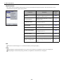
[System] menu
Tool option functions (default setting functions) can be selected from the [System] menu. The functions that can be
selected from the [System] menu are as follows.
Functions
[System] menu
T00056E
Contents
Reference
page
Set Up
Sets the backlight and display
brightness, and the buzzer.
P.36
Unit Conversion
Sets the speed, temperature, pressure,
and flow units.
P.38
Language Select
Selects the language used with the
Intelligent Tester II.
P.37
Brand Select
Sets the brand for the opening screen
(Toyota or Lexus).
P.38
Date/Time
Sets the date and time.
P.37
Version Information
Displays version information for the
Intelligent Tester II.
P.39
Memory Select
Sets the data storage destination
(memory or card).
P.41
Screen Configuration
Corrects the touch panel touch keys.
P.40
Button Configuration
Sets the shortcut keys, and switches
the screen image save function ON/
OFF.
P.41
Bar
The function button displays are switched ON/OFF by touching the [Bar].
Help
When [Help] is touched with [Data List] or [Active Test] selected, an explanation of the item is displayed.
When [Help] is touched with [Utility] selected, an explanation of the functions is displayed.
- 28 -
2 Basic Operations
Basic Operations
Display Operation
Touch panel operation
The display for the Intelligent Tester II is a touch panel. Operations on the display are all operated using your fingers.
To select an item from a list or press a button, briefly tap the item or button with your finger.
T00058E
T00057E
Example of screen displaying items
in a list
Example of a screen displaying
buttons
CAUTION
To protect the display from scratches, always insert the screen overlay.
Always operate the touch panel with your fingers. Never use any other object.
Replacing the screen overlay for the display
When removing the screen overlay, grasp the screen overlay with your fingers and remove.
Use a soft cloth to wipe the surface of the touch panel clean of any dust etc.
When inserting the screen overlay, insert it into the gap between the top section and the bottom section of the display.
T00059E
- 29 -
2 Basic Operations
Scroll bar operation
A scroll bar is displayed on a screen displaying a list. The scroll bar can be used to scroll up and down the list.
If you move your finger up/down while touching the scroll bar, the list scrolls up/down.
Touching
/
Touching and holding
once scrolls the list up/down one line.
/
scrolls the list up/down continuously.
T00060E
Example of screen with scroll bar
displayed
Software keyboard operation
When it is necessary to input characters on the screen, use the software keyboard.
Backspace key
Enter key
T00061E
Space bar
Cursor keys
Methods for use are as follows.
The keyboard can input English alphanumerics.
To delete a character, use the
(backspace) key.
To switch between uppercase and lowercase English letters, use the Shift key.
To input accented characters (such as á and Ä) not displayed on the keyboard, touch the áü key. The keyboard display
switches to accented characters.
- 30 -
2 Basic Operations
Main Unit Operation
The main unit of the Intelligent Tester II has four hardware keys.
All operations of the Intelligent Tester II can be carried out on the display, but four hardware keys are used for frequentlyused functions in order to improve operability.
Scroll up key
Right function key
Scroll down key
Left function key
T00062E
The hardware key functions are as follows.
Hardware key
Functions
Scroll up key
This key is enabled when a list (and a scroll bar) is shown on the display. It scrolls the
list up.
Pressing this key once scrolls the list up one line; holding the key down scrolls the list
up continuously.
Scroll down key
This key is enabled when a list (and a scroll bar) is shown on the display.It scrolls the
list down.
Pressing this key once scrolls the list down one line; holding this key down scrolls the
list down continuously.
Left function key
Used to return from the screen currently being displayed to the onboard/offboard check
screen.
Right function key
Normally used to return to the system select screen.
Used to start/stop measurement during voltage measurement and measurement with
the oscilloscope function.
When screen image saving is set to "ON", pressing this key saves the screen image.
Reference: Page 41 Button Setting Functions (Button Configuration) (Chapter 3.
Default Settings/Tool Option Function)
- 31 -
2 Basic Operations
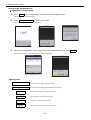
In Case of Error
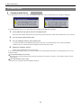
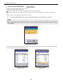
Communication Errors
If a communication error occurs while the Intelligent Tester II is in use, the following error message is displayed.
T00063E
T00064E
If a communications error occurs, check the error according to the following procedure.
1.
Touch [OK] at the top right of the error message window.
This closes the window and returns to the head screen of the function in which the communication error occurred.
2.
Turn the vehicle ignition switch OFF.
3.
Turn the Intelligent Tester II power switch OFF.
A connection defect for the datalink cable may be the cause of a communication error. Check the datalink
connector (DLC 3) connection at the Intelligent Tester II and vehicle sides.
4.
Restart the Intelligent Tester II.
Check if the communication error occurs again.
If so, connect the Intelligent Tester II to another vehicle (of the same model) and check if a communication error occurs
with that vehicle.
If no communication error occurs
There may be a problem with the vehicle. Inspect and repair the vehicle as necessary, in accordance with the vehicle
repair manual.
If a communication error occurs
There may be a problem with the Intelligent Tester II.
- 32 -
2 Basic Operations
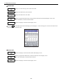
System Errors
If a system error occurs while the Intelligent Tester II is in use, an error message dialog box like the following is displayed.
T00066E
T00065E
T00067E
If a system error occurs, follow the procedure listed below.
1.
Touch OK in the error message dialog box.
2.
Turn the Intelligent Tester II power switch OFF.
3.
Turn the Intelligent Tester II power switch ON to restart the Intelligent Tester II.
If restarting the Intelligent Tester II does not eliminate the system error, write down the error message and ask the
service reception staff.
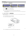
Screen Lock Errors
If there is no response when the touch keys are pressed or the screen locks up when using the Intelligent Tester II, follow
the procedure listed below.
1.
Turn the Intelligent Tester II power switch OFF.
2.
Press the reset switch beside the CF card slot.
T00068E
3.
Turn the Intelligent Tester II power switch ON to restart the Intelligent Tester II.
- 33 -
3 Default Settings
3 Default Settings
3
Default Settings
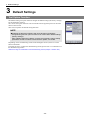
Tool Option Function
The default setting tool option function changes the default settings (the factory settings)
for the Intelligent Tester II.
The various tool option functions can be selected from the [System] menu on the main
menu screen title bar.
This section explains the default setting functions.
NOTE
Updating the diagnosis software will cause all setting parameters
changed using the tool option function to be reset to their default settings
(factory settings).
After updating diagnosis software, go back and manually change setting
parameters to their condition before software update, as needed.
Depending on the manufacturing model of the Intelligent Tester II, there are certain
features that differ.
In regards to how to confirm the manufacturing model, please refer to "Confirmation of
the manufacturing model".
Reference: Page 6 Confirmation of the manufacturing model (Chapter 1. Before Use)
- 35 -
[System] menu
T00069E
3 Default Settings
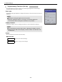
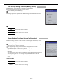
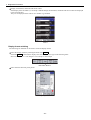
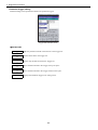
Supplementary Functions (Set Up)
The supplementary functions set the level of back light brightness and the display
contrast, and turn the buzzer ON/OFF.
Back Light
Adjusts the back light brightness. Sliding the indicator to the left increases the level of
brightness.
NOTE
Making the back light brighter uses more power.
When the Intelligent Tester II is running on its internal battery,we
recommend that the back light be dimmed for as possible.
Display Contrast
Adjusts the display contrast. Sliding the indicator to the left darkens the display.
NOTE
For manufacturing model "DN-IT2-002", adjusting the display contrast
settings will not affect actual display contrast. Please note that this is not
a malfunction.
Buzzer
Select ON/OFF for the buzzer (touch sound).
ACTIVE KEY
OK
Activates the selected settings.
Cancel
Returns to the previous settings.
- 36 -
T00070E
3 Default Settings
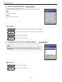
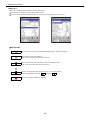
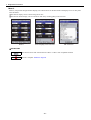
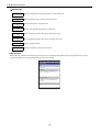
Clock Functions (Date/Time)
The clock functions set the date and time.
The cursor is displayed and the item can be set when the desired item is touched.
Date
Sets the year /month/day.
Clock
Sets the hour:minute:second.
T00071E
ACTIVE KEY
Raises the value in the input column where the cursor is displayed.
Lowers the value in the input column where the cursor is displayed.
OK
Activates the selected settings.
Cancel
Returns to the previous settings.
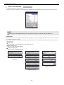
Language Selection Function (Language Select)
The language selection function sets the use language for the Intelligent Tester II.
NOTE
The Intelligent Tester II must be restarted to operate it in the selected
language.
T00262E
ACTIVE KEY
OK
Activates the selected settings.
Cancel
Returns to the previous settings.
- 37 -
3 Default Settings
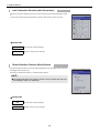
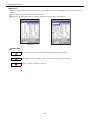
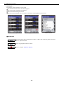
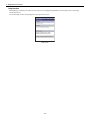
Unit Conversion Function (Unit Conversion)
The unit conversion function sets the conversion units used with the Intelligent Tester
II.
Units for the vehicle speed, temperature, pressure and air flow can be selected.
T00073E
ACTIVE KEY
OK
Activates the selected settings.
Cancel
Returns to the previous settings.
Brand Selection Function (Brand Select)
The brand selection function sets the brand displayed on the opening screen when the
Intelligent Tester II starts up.
Select from TOYOTA, LEXUS, or TOYOTA & LEXUS.
NOTE
The brand selected for the opening screen can be checked the next time
the Intelligent Tester II is started up.
T00074E
ACTIVE KEY
OK
Activates the selected settings.
Cancel
Returns to the previous settings.
- 38 -
3 Default Settings
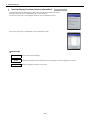
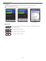
Version Display Function (Version Information)
Version information for the Intelligent Tester II and for the applications used by the
Intelligent Tester II can be checked using the version function.
The screen on the right is the Intelligent Tester II version information screen.
T00075E
The screen on the right is the detailed version information screen.
T00076E
ACTIVE KEY
OK
Activates the selected settings.
Detail
Displays the detailed version information screen enabling a check for application versions.
Back
Returns the display to the previous screen.
- 39 -
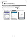
3 Default Settings
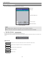
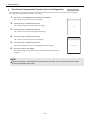
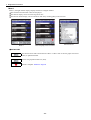
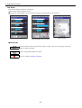
Touch Panel Compensation Function (Screen Configuration)
The touch panel compensation function compensates for the deviation when a key is operated on the touch panel.
The touch panel compensation procedure is as follows.
1.
Touch the + mark displayed in the center of the display.
The + mark moves to the top left of the display.
2.
Touch the new + mark that has moved.
The + mark moves to the bottom left of the display.
3.
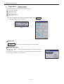
Touch the new + mark that has moved.
The + mark moves to the bottom right of the display.
T00077E
4.
Touch the new + mark that has moved.
The + mark moves to the top right of the display.
5.
Touch the new + mark that has moved.
The screen changes when the + mark disappears from the display.
6.
Touch any point on the display.
The display changes to the opening screen and touch panel compensation is
complete.
T01077E
NOTE
When touching the + mark, always touch for at least one second. The + mark does not move unless
touched it for at least one second.
- 40 -
3 Default Settings
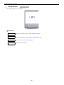
Data Storage Setting Function (Memory Select)
The data storage setting function sets the storage location data.
Either internal memory or PC Card 1 can be selected.
Internal Memory : Internal memory
PC Card1: External memory card 1
The storage capacity is displayed after the data storage location has been selected.
T00079E
ACTIVE KEY
OK
Activates the selected settings.
Cancel
Returns to the previous settings.
Button Setting Functions (Button Configuration)
The button setting functions set short cuts to the left and right function keys on the
main unit, and set image storage for the right function key.
Short cut key settings determine where the screen returns to when the left or right
function key on the main unit is pressed.
The image storage setting switches the image storage function ON/OFF.
The image storage function can store the image being displayed as a file when the
right function key on the main unit is pressed.
Up to 2 such image files can be stored. The 3rd image file will be written over the
oldest file.
The image storage setting returns to the default value (OFF) when the Intelligent
Tester II power goes OFF. This setting is always OFF immediately after the
Intelligent Tester II starts up. To enable this function, you must set it to ON after
startup.
ACTIVE KEY
OK
Activates the selected settings.
Cancel
Returns to the previous settings.
- 41 -
T00080E
4 Diagnostics Functions
4 Diagnostics Functions
4
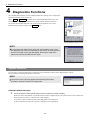
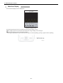
Diagnostics Functions
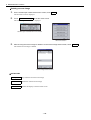
The onboard/offboard check screen is displayed after the opening screen is displayed
when the Intelligent Tester II starts up.
When Auto or Manual is touched on the onboard/offboard check screen, the
Intelligent Tester II begins communication with the vehicle and check the ECU.
To execute measurement functions such as the oscilloscope that do not require
communication with the vehicle, touch Utility .P.55
T00081E
Onboard/offboard check screen
NOTE
If you execute the OBD function when the vehicle battery is 8V or less,
the ABS lamp may come on, depending on the vehicle. A warning screen
like the one shown on the right will appear. Recharge or replace the
battery and execute the OBD function again.
Warning screen
T00082E
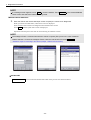
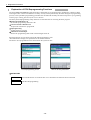
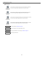
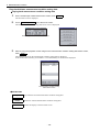
System Selection
It is necessary to select the diagnostics system (the system within the vehicle) when diagnosing the vehicle.
The procedure for selecting the system is as follows.
NOTE
The screen on the right may appear before selecting the system
procedure. Select the vehicle to be diagnosed.
T00083E
Vehicle select screen
Automatic Vehicle Selection
1.
Touch the list box on the system select screen to select the system category.
When the vehicle information is acquired from the vehicle computer (ECU), the system select screen is displayed.
Select powertrain, chassis, or body as the system category.
A list of the vehicle mounted systems being diagnosed is then displayed.
If vehicle information cannot be acquired, a message screen is displayed.
- 43 -
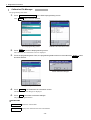
4 Diagnostics Functions
NOTE
If a message screen appears, touch OK to close the window. Touch Manual on the onboard/offboard
check screen and select the vehicle to be diagnosed.
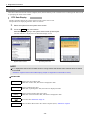
Manual Vehicle Selection
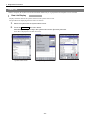
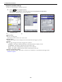
1.
Enter the data on the vehicle data input screen to specify the vehicle to be diagnosed.
When you touch each data button, a data select screen is displayed.
Select the data of the vehicle to be diagnosed from the data select screen.
Touch OK and the system select screen is displayed.
Operation from this point is the same as when selecting an automatic vehicle.
NOTE
The Intelligent Tester II communicates with the vehicle computer (ECU) even in the case of Manual
Vehicle Selection. Connect the Intelligent Tester II with the vehicle before touching Manual .
Reference: Page 14 Connecting to the Vehicle (Chapter 1. Before Use/Connection)
T00084E
Vehicle data input screen
T00085E
Data select screen
T00086E
Previous vehicle select screen
ACTIVE KEY
Previous Vehicle
You can select the manual select data of the previous ten selected vehicles.
- 44 -
4 Diagnostics Functions
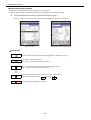
2.
Touch the system to undertake diagnosis from the system list.
T00087E
System select screen
Message screen
T00088E
NOTE
When you select the system, a warning screen like the one shown on the
right may be displayed. Make sure you understand the message
displayed before carrying out vehicle diagnosis.
Warning screen
T00089E
NOTE
After the Intelligent Tester II is started, the system select screen is
displayed.
To reselect a system after having moved to other processing, press the
right function key on the main unit or select the menu bar [Function] menu
list -> [System Select]. This displays the system select screen.
T00090E
[Function]Menu list
ACTIVE KEY
Bus Check
Starts the CAN bus check.
- 45 -
4 Diagnostics Functions
DTC Check
DTC data is data stored in the vehicle computer (ECU) internal memory when a trouble occurs. Checking DTC data can aid
in specifying the cause of the trouble.
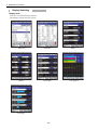
DTC Data Display
Displays the DTC data for the system selected on the system select screen.
The procedure for displaying the DTC data is as follows.
1.
Select the system from the system select screen.
2.
Touch the DTC main menu button.
Alternatively, touch [DTC] in the system select screen [Function] list.
The DTC data list is displayed on the DTC data display screen.
T00092E
T00091E
System select screen
[Function] Menu list
T00093E
DTC data display screen
NOTE
A "!" displayed at the left of DTC data shown in orange means that freeze frame data has been recorded
for that data.
Reference: Page 50 Freeze Frame Data Display (Chapter 4. Diagnostics Functions/DTC Check)
ACTIVE KEY
Current
Displays the current DTC data.
When there is DTC data, this button is displayed in blue.
Pending
Displays pending DTC data.
When there is pending DTC data, this button is displayed in blue.
History
Displays historical DTC data (past codes).
When there is historical DTC data, this button is displayed in blue.
Saves DTC data. Reference: Page 47
Clear
Clears the DTC data stored in the vehicle computer (ECU). Reference: Page 49
- 46 -
4 Diagnostics Functions
DTC Data Storage
DTC data can be stored. The factory setting for the data storage destination is the internal memory. The data storage
destination can be changed using the data storage setting function.
Reference: Page 41 Data Storage Setting Function (Memory Select) (Chapter 3. Default Settings/Tool Option Function)
The procedure for saving the DTC data is as follows.
1.
From the DTC data display screen function buttons, touch
.
The DTC data save screen is displayed.
2.
The set file name is displayed on the DTC data save screen.
If this file name is correct, touch Save .
To save to a different file, input the name of that file, and then touch Save .
Reference: Page 30 Software keyboard operation (Chapter 2. Basic Operations/Basic Operations/Display
Operation)
The first time this screen is displayed, "Vehicle model_model year_serial number" is set automatically as the file
name displayed.
T00094E
T00095E
DTC data display screen
DTC data save screen
ACTIVE KEY
Save
Cancel
Saves DTC data.
Cancels DTC data saving.
NOTE
The stored DTC data can be played back at any time. The Intelligent Tester II does not need to be
connected to the vehicle for playback.
Reference: Page 82 DTC Playback (Chapter 5. Saved Data Playback Functions)
- 47 -
4 Diagnostics Functions
If the storage memory is full, the DTC data delete verification dialog box is displayed and unnecessary DTC data can be
deleted.
T00096E
DTC data delete verification dialogue
ACTIVE KEY
Delete Files
Displays a list of stored data.
Cancel
Cancels DTC data deletion.
- 48 -
4 Diagnostics Functions
DTC Data Clear
The procedure for clearing the DTC data is as follows.
1.
From the DTC data display screen function buttons, touch Clear .
The DTC data clear dialog box is displayed.
2.
On the DTC data clear dialog box, touch Yes .
Delete DTC data by following the operating instructions on the screen.
T00098E
DTC data clear dialog box
T00097E
DTC data display screen
NOTE
A Vehicle data input screen is displayed with certain vehicles. Follow the instructions on the screen.
T00099E
Vehicle data input screen
- 49 -
4 Diagnostics Functions
Freeze Frame Data Display
Displays freeze frame data related to the DTC data.
There are two types of freeze frame data:
Single freeze frame data : ECU data recorded when the DTC data is generated.
Multi freeze frame data : ECU data recorded when the DTC data is generated and before and after it is generated.
The procedure for displaying freeze frame data is as follows.
1.
On the DTC data display screen, touch the DTC data displayed in orange with "!" to the left.
NOTE
A "!" displayed to the left of DTC data shown in orange indicates that freeze frame data has been recorded
for that data.
T00100E
DTC data display screen
The single freeze frame data display screen is displayed for single freeze frame data. The multi freeze frame data display
screen is displayed for multi freeze frame data.
T00101E
T00102E
Multi freeze frame data
display screen
Single freeze frame data
display screen
- 50 -
4 Diagnostics Functions
Single freeze frame data display
The single freeze frame data display screen is displayed for single freeze frame data.
T00103E
Single freeze frame data
display screen
ACTIVE KEY
Exit
Returns the display to the DTC data display screen.
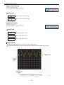
Multi freeze frame data display
The multi freeze frame data display screen is displayed for multi freeze frame data.
T00104E
Multi freeze frame data
display screen
The Multi Frame Number for multi freeze frame data currently being displayed is shown in orange. The Multi Frame
Number is a serial number.
- 51 -
4 Diagnostics Functions
ACTIVE KEY
Displays a screen showing a list of time series data.
Displays the data for the previous frame.
Displays the data for the next frame.
Displays a graph of the data history selected on the multi freeze frame data display screen. This
is not valid unless an item has been selected.
Exit
Returns the display to the DTC data display screen.
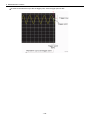
Touching
on the multi freeze frame data display screen displays a screen showing a list of time series data for the
displayed multi freeze frame data.
T00105E
Time series data list display screen
ACTIVE KEY
Returns the display to the multi freeze frame data display screen.
Displays a graph of the data history selected on the time series display screen.
This is not valid unless an item has been selected.
Exit
Returns the display to the DTC data display screen.
- 52 -
4 Diagnostics Functions
Multi freeze frame data graph display
When data is selected on the multi freeze frame data display screen or the time series display screen and then
touched, a multi freeze frame data graph screen is displayed.
T00106E
Multi freeze frame data
graph screen
ACTIVE KEY
Exit
Returns the display to the previous screen.
- 53 -
is
4 Diagnostics Functions
Data List
Vehicle computer (ECU) data can also be monitored numerically or in graph form and snapshots can be recorded.
Data List Display
Displays the ECU data for the system selected on the system select screen.
The procedure for displaying the ECU data is as follows.
1.
Select the system with the system select screen.
2.
Touch the Data List main menu button.
Alternatively, touch [Data List] in the system select screen [Function] menu list.
ECU data is displayed on the data list screen.
T00107E
System select screen
T00109E
[Function] menu list
- 54 -
T00108E
Data list screen
4 Diagnostics Functions
Measurement group selection
Data required for diagnosing a specific breakdown can be grouped.
The ECU data belonging to a measurement group can be displayed by selecting that group.
1.
From the data list screen list box, select the measurement group.
When you select a measurement group, the ECU data belonging to that group is displayed.
T00110E
T00111E
Data list screen
Measurement group select screen
ACTIVE KEY
Starts the data list manager and adds the displayed data. Reference: Page 71
Ends display of the selected data.
This is not valid unless data has been selected.
Moves the selected data to the head of the list and holds it there.
This is not valid unless data has been selected.
Returns the data held at the head of the list to its original position.
When the held data is selected,
changes to
.
Records a snapshot. Reference: Page 65
- 55 -
4 Diagnostics Functions
Display Switching
Display form
There are seven data list display formats.
These display formats are shown below.
T00113E
T00112E
Data List 1
Data List 2
T00115E
Meter 2
T00114E
Meter 1
T00117E
T00116E
Line Graph 1
T00118E
Bar Graph
- 56 -
Line Graph 2
4 Diagnostics Functions
Display of maximum, minimum and current values
If the display forms are Meter 1, Line Graph 1 and Bar Graph, the maximum, minimum and current values are displayed
to the left of the data.
They are not displayed if the value is not a number e.g. ON/OFF.
T00119E
Meter 1
Display format switching
The following two methods can be used to switch the display format.
Select the display format by touching the main menu View .
Each time View is touched, the display form switches to the next type in the following order:
Data List 1-> Meter 1-> Line Graph 1-> Line Graph 2-> Bar Graph.
T00120E
Main Menu Buttons
Select from the menu bar [View] menu.
T00121E
[View] menu
- 57 -
4 Diagnostics Functions
Data List 1
Data List 1 (number display) displays the data numerically.
A measurement group can be selected with the list box.
You can switch the function button display on and off by touching [Bar] on the menu bar.
T00123E
T00122E
Data List 1
With the list box pulled down
ACTIVE KEY
Starts the data list manager and adds the displayed data. Reference: Page 71
Stops display of the selected data.
This is not valid unless data has been selected.
Moves the selected data to the head of the list and holds it there.
This is not valid unless data has been selected.
Returns the data held at the head of the list to its original position.
When the held data is selected,
changes to
.
Records a snapshot. Reference: Page 65
- 58 -
4 Diagnostics Functions
Data List 2
Data List 2 (compressed number display) uses abbreviations for the data names and displays twice as many data items as
Data List 1.
A measurement group can be selected using the list box.
The function button display can be switched on and off by touching [Bar] on the menu bar.
T00124E
T00125E
Data List 2
With the list box pulled down
ACTIVE KEY
Starts the data list manager and adds the displayed data. Reference: Page 71
Ends display of the selected data. This is not valid unless data has been selected.
Records a snapshot. Reference: Page 65
- 59 -
4 Diagnostics Functions
Meter 1
Meter 1 (enlarged number display) displays the data as enlarged numbers.
The maximum and minimum values are displayed.
The data for display can be selected using the list box.
The function button display can be switched on and off by touching [Bar] on the menu bar.
T00126E
Meter 1
T00127E
When the [Bar] menu is touched
T00128E
With the list box
ACTIVE KEY
Switches the buzzer that sounds when the "Max" or "Min" value or the line graph vertical axis
(value) is updated ON/OFF.
Sets the line graph horizontal axis (time).
Records a snapshot. Reference: Page 65
- 60 -
4 Diagnostics Functions
Meter 2
Meter 2 (compressed enlarged number display) uses abbreviations for the data names and displays twice as many data
items as Meter 1.
The data for display can be selected using the list box.
The function button display can be switched on and off by touching [Bar] on the menu bar.
T00129E
Meter 2
T00131E
T00130E
When the [Bar] menu is touched
With the list box
ACTIVE KEY
Switches the buzzer that sounds when the "Max" or "Min" value is updated ON/OFF.
Records a snapshot. Reference: Page 65
- 61 -
4 Diagnostics Functions
Line Graph 1
Line Graph 1 displays the data as a line graph.
The maximum and minimum values are displayed.
The current values of the data are displayed.
Data can be selected using the list box.
The function button display can be switched on and off by touching [Bar] on the menu bar.
T00132E
Line Graph 1
T00133E
When the [Bar] menu is touched
T00134E
With the list box
ACTIVE KEY
Switches the buzzer that sounds when the "Max" or "Min" value or the line graph vertical axis
(value) is updated ON/OFF.
Sets the line graph horizontal axis (time).
Records a snapshot. Reference: Page 65
- 62 -
4 Diagnostics Functions
Line Graph 2
Line Graph 2 (line graph combined display) displays multiple data sets as a line graph on the same axis.
Data can be selected using the list box.
The function button display can be switched on and off by touching [Bar] on the menu bar.
T00135E
Line Graph 2
T00136E
When the [Bar] menu is touched
T00137E
With the list box
ACTIVE KEY
Switches the buzzer that sounds when the "Max" or "Min" value or the line graph vertical axis
(value) is updated ON/OFF.
Sets the line graph horizontal axis (time).
Sets the ground position for the selected data.
Records a snapshot. Reference: Page 65
- 63 -
4 Diagnostics Functions
Bar Graph
This function displays the data as a bar graph.
Data can be selected using the list box.
The function button display can be switched on and off by touching [Bar] on the menu bar.
T00138E
Bar Graph
T00139E
T00140E
With the list box
When the [Bar] menu is touched
ACTIVE KEY
Switches the buzzer that sounds when the "Max" or "Min" value or the line graph vertical axis
(value) is updated ON/OFF.
Sets the line graph horizontal axis (time).
Records a snapshot. Reference: Page 65
- 64 -
4 Diagnostics Functions
Snapshots
Data in the data list can be recorded/saved/played back. In addition, settings can be performed for snapshot operation.
Snapshot recording/saving
The procedure for recording/saving snapshots is as follows.
1.
Touch the
function button.
Alternatively, in the data list screen [Function] menu list, touch [Snapshot Record].
The snapshot record/save screen is displayed.
T00141E
T00142E
Data list screen
2.
[Function] menu list
Data recording/saving starts automatically.
When the data recording/saving ends, the system goes into playback/new recording standby mode.
When recording
T00143E
When saving
- 65 -
T00144E
T00145E
Playback/new recording standby
4 Diagnostics Functions
"Vehicle model_model year_serial number" is set automatically as the file name saved.
You can set the snapshot flag by touching [
] when recording.
NOTE
The snapshot flag stores the point as a mark for the data time elapsed. During playback, you can move
quickly to points using the snapshot flags.
Up to five snapshot flags can be set.
Reference: Page 86 Playback With Snapshot Flag Set (Chapter 5. Saved Data Playback Functions/Snapshot
Playback)
ACTIVE KEY
Sets snapshot operations. Reference: Page 68
Exit
Ends the snapshot.
Stops recording/playback and returns to the start of the data.
Recording starts.
Playback starts.
Sets a snapshot flag.
- 66 -
4 Diagnostics Functions
How to use the optional accessory Trigger Snapshot
Connecting the Trigger Snapshot
T00146E
CAUTION
When connecting the probe to the Intelligent Tester II, gently insert it straight into the connector.
Inserting the probe at a slant can break the connector pins.
How to use Trigger Snapshot
1.
Press the Trigger Snapshot button while the data list is displayed.
Data recording begins.
2.
Press the Trigger Snapshot button during data recording.
A snapshot flag is set.
NOTE
Trigger Snapshot can be used to set snapshot flags in a maximum of five places.
Reference: Page 86 Playback With Snapshot Flag Set (Chapter 5. Saved Data Playback Functions/Snapshot
Playback)
Pressing the Trigger Snapshot button after five snapshot flags are set stops data recording.
- 67 -
4 Diagnostics Functions
Snapshot operation settings
Settings can be performed for snapshot operation.
1.
Touch
on the snapshot screen.
Alternatively, in the data list screen [Function] list, touch [Snapshot Configuration].
The snapshot operation setting screen is displayed.
T00147E
Snapshot screen
T00148E
[Function] Menu list
T00149E
Snapshot operation setting screen
The setting contents are as follows.
Record Time
Sets the recording time.
Select from 5s/10s/15s/30s/1 min./2 min./5 min.
Trigger Point
Sets the percentage of the recording time saved as data before the trigger is pressed.
Trigger
Sets the type of trigger. The types of triggers are as follows.
Manual : The trigger is applied manually by touching the data list display section.
Parameter : The trigger is applied at the set parameter value.
DTC : The trigger is applied when a diagnostics code is detected.
MIL : The trigger is applied when the engine warning lamp comes ON.
Trigger Configuration Button
Sets the parameter triggers. This button is only active if “Parameter” is selected from the trigger items.
Reference: Page 69
- 68 -
4 Diagnostics Functions
Parameter trigger setting
Detailed settings can be performed related to the parameter triggers.
T00150E
Trigger data selection screen
ACTIVE KEY
Adds only the data selected in the item list to the Trigger list.
Deletes all the data in the Trigger list.
Deletes only the data selected in the Trigger list.
Moves the data selected in the Trigger list up one space.
Moves the data selected in the Trigger list down one space.
OK
Displays the Parameter trigger level setting screen.
- 69 -
4 Diagnostics Functions
Parameter trigger level setting
Detailed settings can be performed related to the level of parameter triggers.
T00151E
Value setting screen
Record Quantity : Sets the number of times snapshot is repeated.
ACTIVE KEY
Applies the trigger when the ECU data is higher than or equal to the set value.
Applies the trigger when the ECU data is lower than or equal to the set value.
=
Applies the trigger when the ECU data equals the set value.
T00152E
AND
Sets the trigger level.
Applies the trigger when all set conditions are satisfied.
OR
Applies the trigger when some of the set conditions are satisfied.
Add
Returns to the trigger data selection screen. (Trigger data can be added.)
Exit
Returns to the Snapshot operation setting screen.
- 70 -
4 Diagnostics Functions
Data List Manager
With the data list manager, you can change display data lists and other data set in measurement groups and create new
measurement groups.
The procedure for starting the data list manager is as follows.
1.
To change the display data, select the related measurement group on the data list screen.
2.
In the data list screen [Function] menu, touch [Data List Manager]. Or touch the
function button.
The data list manager screen is displayed.
T00155E
Function buttons
T00141E
Data list screen
3.
T00142E
[Function] menu list
Change the display data on the data list manager screen.
T00157E
T00156E
When the display data is decided
With the display data selected
- 71 -
4 Diagnostics Functions
ACTIVE KEY
Adds only the data selected in the item list to the custom list.
Adds all the data in the item list to the custom list.
Deletes all the data in the custom list.
Deletes only the data selected in the custom list.
Moves the data selected in the custom list up one space.
Moves the data selected in the custom list down one space.
Save
OK
Sets the custom list data.
Returns the display to the previous screen.
Help function
When [Help] is touched in the menu bar, the help screen is displayed and guidance concerning the data list is shown.
To close the help screen, touch [OK] at the top right of the screen.
Help screen
- 72 -
T00158E
4 Diagnostics Functions
Active Test
The active test is a function to forcibly drive relays, actuators, solenoids, etc.
If they are driven normally in the active test, it is possible to judge circuits as normal from the ECU to relays, actuators,
solenoids, etc.
Active Test Item Selection
Selects the active test items.
1.
From the main menu buttons, touch Active Test .
Alternatively, from the [Function] menu list, touch [Active Test].
The active test item select screen is displayed.
2.
On the active test item select screen, select the test items and then touch Enter .
The active test starts.
T00159E
Main menu buttons
T00160E
[Function] menu list
ACTIVE KEY
Enter
Starts the active test for the selected items.
This is not valid unless a test item has been selected.
- 73 -
T00161E
Active test item select screen
4 Diagnostics Functions
Active Test Execution
Actuators are driven by the control box.
During an active test, the data list can be displayed simultaneously and measurement groups selected from the list box.
T00162E
Active test execution screen
NOTE
No data list can be displayed during an active test according to the ECUs selected (ABS,etc.).
Control box
When an active test is executed, the control box for varying the drive value is displayed under the test item, so it is possible
to set the active test drive value.
There are three types of control box as follows, and the system switches automatically among them according to the test
items selected.
Binary type
The drive value is varied between two values (ON/OFF, etc.).
Digital change type
The drive value is changed digitally.
Analog change type
The drive value is changed in analog.
T00163E
Binary type
T00165E
Analog change type
T00164E
Digital change type
- 74 -
4 Diagnostics Functions
Help function
When [Help] is touched in the menu bar, the help screen is displayed and guidance concerning the active test being
executed is shown.
To close the help screen, touch [OK] at the top right of the screen.
T00166E
Help screen
- 75 -
4 Diagnostics Functions
Utilities
The Intelligent Tester II has a utility with various functions.
The procedure for starting the utility is as follows.
1.
From the main menu buttons, touch Utility .
Alternatively, touch [Utility] in the [Function] menu list.
The utility function select screen is displayed.
2.
Touch the function to be executed on the utility function select screen.
T00167E
Main Menu Buttons
T00168E
[Function] Menu list
- 76 -
T00169E
Utility function select screen
4 Diagnostics Functions
Explanation of Button Operations
This section explains button operations using the utility function ABS air bleeding as an example.
T00170E
T00171E
Next screen
Initial screen
ACTIVE KEY
Next >
Moves the display to the next screen.
< Back
Returns the display to the previous screen.
Cancel
Cancel the utility function.
NOTE
Each screen displays notes and the procedure for proceeding with the operation. Proceed with the
operation according to the procedures noted in the service manual and the contents displayed on the
screen.
- 77 -
4 Diagnostics Functions
Explanation of ECU Reprogramming Functions
The ECU REPROGRAMMING application allows authorized service professionals to update ECU software without
removing the ECU. Please note that there are many security checks performed by the ECU during the reprogramming
process, so the specified reprogramming procedure must be followed carefully. DO NOT attempt ECU reprogramming
without proper training from the Toyota service division.
The utility ECU Reprogramming utility functions are four functions for rewriting the ECU program.
Download Calibration File
Downloads programming data from a PC.
Current Vehicle Calibration ID
Acquires the vehicle ECU program ID.
Reprogramming
Updates the ECU program.
Calibration File Manager
Deletes the programming data stored in the Intelligent Tester II.
Select the function for execution from the ECU Reprogramming screen.
"Item Information" displays an explanation of the selected function.
The ECU to be reprogrammed can be selected from the system list box.
T00172E
T00173E
ECU Reprogramming screen
With the list box pulled down
ACTIVE KEY
Enter
Exit
The selected function is executed. This is not valid unless the function has been selected.
Ends ECU Reprogramming.
- 78 -
4 Diagnostics Functions
Calibration File Manager
The programming data delete
1.
Touch Calibration File Manager in the ECU Reprogramming screen.
Then, Enter button becomes effective.
T00174E
T00175E
ECU Reprogramming screen
2.
Calibration file information screen
Touch Enter in the ECU Reprogramming screen.
The Calibration file information screen is displayed.
3.
Touch the programming data. Then, the programming data becomes covered blue and Delete button
becomes effective.
T00177E
Delete verification dialogue
T00176E
Programming data selected
4.
Touch Delete in the Calibration file information screen.
The Delete verification dialogue is displayed.
5.
Touch Yes in the Delete verification dialogue.
The programming data deletes.
ACTIVE KEY
Delete
Deletes the selected data.
Open
Displays the calibration ID of the selected data.
- 79 -
4 Diagnostics Functions
Help function
When [Help] is touched in the menu bar, the help screen is displayed and guidance concerning the utility functions is
shown.
To close the help screen, touch [OK] at the top right of the screen.
T00178E
Help screen
- 80 -
5 Saved Data Playback Functions
5 Saved Data Playback Functions
5
Saved Data Playback Functions
The Intelligent Tester II not only has functions for diagnosing breakdowns in real time,
but also has functions that can play back saved data afterwards.
The saved data playback functions do not require the Intelligent Tester II and the vehicle
to connect.
The onboard/offboard check screen is displayed after the opening screen when the
Intelligent Tester II is started up.
The saved data playback functions are the DTC playback and snapshot playback
functions, and they can be started from the [Function] menu.
T00179E
Onboard/Offboard check screen
DTC Playback
Plays back saved DTC data.
The procedure for playing back DTC data is as follows.
1.
From the [Function] menu list, touch [Saved Data Review].
The playback data select screen is displayed and a list of saved DTC data files is displayed.
2.
On the playback data select screen, select the DTC data for playback and then touch
.
When DTC data is selected, file information is displayed in the File Information column. Touching
back the selected DTC data.
T00090E
[Function]Menu list
T00181E
Playback data select screen
- 82 -
plays
T00182E
DTC data playback screen
5 Saved Data Playback Functions
ACTIVE KEY
Opens the selected DTC data and plays it back.
Deletes the selected DTC data.
Current
Displays saved the current DTC data.
When there is DTC data, this button is displayed in blue.
Pending
Displays saved pending DTC data.
When there is pending DTC data, this button is displayed in blue.
History
Displays saved historical DTC data (past codes).
When there is historical DTC data, this button is displayed in blue.
Exit
Ends playback data selection. (Playback data select screen)
Returns the display to the playback data select screen. (When saved DTC data is played back.)
- 83 -
5 Saved Data Playback Functions
Snapshot Playback
Plays back stored snapshot data.
The procedure for playing back snapshot data is as follows.
1.
From the [Function] menu list, touch [Snapshot Review].
The playback data select screen is displayed and a list of saved snapshot data files is displayed.
2.
On the playback data select screen, select the snapshot data for playback and then touch the
function button.
The selected snapshot is played back.
[Function] menu list
T00183E
T00184E
Playback data select screen
T00185E
Snapshot data playback screen
NOTE
"DL" and "AT" may be displayed in the playback data selection screen Function column. "DL" means that
the snapshot is from the data list,and "AT" means that it was saved while an active test was executed.
- 84 -
5 Saved Data Playback Functions
ACTIVE KEY
Displays the playback screen and plays back the data.
Deletes the selected data.
File Open
Exit
Displays the playback data select screen.
Ends playback data selection. (Playback data select screen)
Returns the display to the playback data select screen. (During snapshot dataplayback.)
Stops playback and returns to the start of the data.
Pauses playback.
Fast forwards the data playback.
Starts the data playback.
Fast rewinds the data playback.
Moves to a point at which the snapshot flag is set and plays back from there.
T00186E
The playback position can be changed by touching
the scroll bar to the left and right.
This bar is only valid during data list playback.
- 85 -
or by moving
5 Saved Data Playback Functions
Playback With Snapshot Flag Set
When a snapshot flag is set, you can quickly move to the set point during snapshot playback. There are two methods for
playback when a snapshot flag has been set.
During normal playback, when a point is reached for which a snapshot flag is set, "
" is displayed in red. When
the set point is passed, the "
" returns to its original color and playback continues.
"
is touched during playback, the snapshot flag point is displayed. When this point is selected, the "
displayed in red and snapshot data for the selected point is played back.
The above "
" is displayed in red for about 1 second, and the buzzer sounds at this time.
The playback screen when a snapshot flag is set is as follows.
T00188E
Snapshot flag set point
playback screen
T00187E
Screen for selecting point
where snapshot flag is set.
- 86 -
is
5 Saved Data Playback Functions
ACTIVE KEY
File Open
Exit
Displays the playback data select screen.
Returns the display to the playback data select screen.
Stops playback and returns to the start of the data.
Pauses playback.
Fast forwards the data playback.
Starts the data playback.
Rewinds the data playback.
Displays the dialog box for selecting the point where a snapshot flag is set.
T00189E
The playback position can be changed by touching
the scroll bar to be the left and right.
This bar is only valid during data list playback.
- 87 -
or by moving
6 Measurement Functions
6 Measurement Functions
6
Measurement Functions
Voltage Measurement Functions
A voltage meter probe can be connected to the Intelligent Tester II for voltage measurement.
Measurement Function Selection Menu
1.
From the main menu buttons of the system select screen, touch Utility .
The function select screen is displayed.
2.
On the function select screen, touch Voltage meter .
The voltage display screen is shown and the voltage currently being measured is displayed in real time.
T00190E
System select screen
T00191E
Function select screen
- 89 -
T00192E
Voltage display screen
6 Measurement Functions
Voltage Display
The voltage display screen is displayed.
T00193E
Voltage display screen
ACTIVE KEY
Wave Form
Displays the waveform display screen. Reference: Page 91
Menu
Saves/plays back/deletes screen images. Reference: Page 94
CAL
Executes calibration. Reference: Page 93
EXIT
Ends voltage measurement.
- 90 -
6 Measurement Functions
Waveform Display
The waveform display screen is displayed.
T00194E
Waveform display screen
The following operations can be executed on the waveform display screen.
The voltage (vertical axis) and time (horizontal axis) range settings can be changed.
Waveform updating can be stopped and resumed.
Pressing the right function key on the main unit stops waveform updating; pressing it again resumes updating.
T00218E
- 91 -
6 Measurement Functions
ACTIVE KEY
Voltage axis
enlargement
Voltage axis
reduction
Time axis
enlargement
Time axis
reduction
CAL
The waveform is enlarged vertically each time the button is touched.
The current voltage range is displayed at the top of the button.
The waveform is reduced vertically each time the button is touched.
The current voltage range is displayed at the top of the button.
The waveform is enlarged horizontally each time the button is touched.
The current time range is displayed at the top of the button.
The waveform is reduced horizontally each time the button is touched.
The current time range is displayed at the top of the button.
Executes calibration. Reference: Page 93
Meter
Returns the display to the voltage display screen.
Menu
Saves/plays back/deletes screen images. Reference: Page 94
Exit
Ends voltage measuremen.
- 92 -
6 Measurement Functions
Calibration
Calibrates the zero point.
1.
Touch CAL on the voltage display screen or the waveform display screen.
The calibrating dialog box is displayed.
T00196E
T00195E
Waveform display screen
Voltage display screen
2.
Connect the voltage measurement tester probe to the reference point.
3.
On the calibrating dialog box, touch OK .
The calibrating dialog is displayed. When the calibration is complete, the hint dialog box is displayed.
Do not remove the probe during calibration.
T00197E
T00198E
Calibrating dialog box
4.
Calibrating dialog box
Check the contents of the hint dialog, then touch OK .
When calibration ends, the tip dialog box is displayed automatically.
This dialog displays an explanation for stopping/resuming waveform updating using the right function key on the
main unit.
T00199E
Hint dialog box
- 93 -
6 Measurement Functions
Screen Image Save/Playback/Delete
Saves/plays back/deletes screen images.
Screen image save
1.
Touch Menu on the voltage display screen or the waveform display screen.
The file menu screen is displayed.
2.
Touch Save Screen Copy on the file menu screen.
The screen image save screen is displayed.
T00202E
File menu screen
T00201E
T00200E
Waveform display screen
Voltage display screen
3.
The set file name is displayed on the screen image save screen.
If this file name is correct, touch Save .
To a different file, input the name of that file and then touch Save .
A comment to be attached to the saved data can be input in the comment column.
Reference: Page 30 Software keyboard operation (Chapter 2. Basic Operations/Basic Operations/Display
Operation)
"File creation date and time_serial number" is set automatically as the file name displayed.
T00203E
T00204E
Screen image save screen
Screen image playback screen
- 94 -
6 Measurement Functions
ACTIVE KEY
SAVE Screen Copy
Executes screen image save processing.
OPEN Screen Copy
Executes screen image playback/delete processing.
Exit
Save
Cancel
Returns the display to the previous screen.
Saves a screen image.
Returns the display to the file menu screen.
- 95 -
6 Measurement Functions
Screen Image Playback/Delete
Playing back a screen image
1.
Touch Menu on the voltage display screen or the waveform display screen.
The file menu screen is displayed.
2.
Touch Open Screen Copy on the file menu screen.
The screen image select screen is displayed.
T00207E
File menu screen
T00205E
Voltage display screen
3.
T00206E
Waveform display screen
After touching the playback screen image on the screen image select screen, touch Open .
The playback screen for the selected screen image is displayed.
T00208E
Screen image select screen
T00209E
Screen image playback screen
ACTIVE KEY
Save Screen Copy
Executes screen image save processing.
Open Screen Copy
Executes screen image playback/delete processing.
Exit
Returns the display to the previous screen.
Open
Plays back the selected screen image.
Delete
Deletes the selected screen image.
Cancel
Returns the display to the file menu screen.
- 96 -
6 Measurement Functions
Deleting a screen image
1.
Touch Menu on the voltage display screen or the waveform display screen.
The file menu screen is displayed.
2.
Touch Open Screen Copy on the file menu screen.
The screen image select screen is displayed.
T00212E
File menu screen
T00210E
T00211E
Voltage display screen
3.
Waveform display screen
After touching the screen image for deletion on the screen image select screen, touch Delete .
The selected screen image is deleted.
T00213E
Screen image select screen
ACTIVE KEY
Save Screen Copy
Executes screen image save processing.
Open Screen Copy
Executes screen image playback/delete processing.
EXIT
Returns the display to the previous screen.
OPEN
Plays back the selected screen image.
Delete
Deletes the selected screen image.
Cancel
Returns the display to the file menu screen.
- 97 -
6 Measurement Functions
Oscilloscope Functions
To use the oscilloscope function, it is necessary to connect the optional oscilloscope cartridge.
The oscilloscope probes can be connected to the Intelligent Tester II to observe the voltage waveform for the signals input to
the channels.
Do not connect the AC/DC adapter to the Intelligent Tester II, when using the oscilloscope function.
Oscilloscope Measurement Menu
1.
From the main menu buttons of the system select screen, touch Utility .
The function select screen is displayed.
2.
On the function select screen, touch Oscilloscope .
The oscilloscope measurement screen is displayed.
T00214E
System select screen
T00216E
T00215E
Function select screen
Oscilloscope measurement menu
screen
ACTIVE KEY
Menu
EXIT
Trigger
Saves/plays back/deletes screen images and measurement condition setting data.
Reference: Page 105
Ends the oscilloscope function.
Displays the trigger menu screen. Reference: Page 101
- 98 -
6 Measurement Functions
Waveform Display
The following operations can be executed on the waveform display screen.
The voltage (vertical axis) and time (horizontal axis) range settings can be
changed.
The ground level (0V position) can be set for the selected channel.
NOTE
The voltage (vertical axis) range and ground level (0V position) are set for
the selected channel.
Waveform updating can be stopped and resumed.
Pressing the right function key on the main unit stops waveform updating;
pressing it again resumes updating.
T00217E
Waveform display screen
T00218E
- 99 -
6 Measurement Functions
ACTIVE KEY
Ch1
The channel for the voltage (vertical axis) range and ground level (0V position)is set to "Ch1".
When this is selected, the button is displayed in blue.
Ch2
The channel for the voltage (vertical axis) range and ground level (0V position)is set to "Ch2".
When this is selected, the button is displayed in blue.
Menu
Exit
Trigger
Voltage axis
enlargement
Voltage axis
reduction
Time axis
enlargement
Time axis
reduction
Saves/plays back/deletes screen images and measurement condition setting data.
Reference: Page 105
Ends the oscilloscope function.
Displays the trigger menu screen. Reference: Page 101
Vertically enlarges the waveform for the selected channel.
The current voltage range is displayed to the right of the selected channel.
Vertically reduces the waveform for the selected channel.
The current voltage range is displayed to the right of the selected channel.
The waveform is enlarged horizontally each time the button is touched.
The current voltage time range is displayed at the top of the button.
The waveform is reduced horizontally each time the button is touched.
The current voltage time range is displayed at the top of the button.
Raises the ground level (0V position) for the selected channel.
Lowers the ground level (0V position) for the selected channel.
- 100 -
6 Measurement Functions
Trigger Menu
Detailed settings can be performed for a parameter trigger.
Trigger channel setting
Trigger mode setting
Trigger level setting
Trigger slope switching
Trigger point setting
1.
On the oscilloscope measurement menu screen, touch Trigger .
The trigger menu screen is displayed.
T00219E
Oscilloscope measurement menu
screen
T00220E
Trigger menu screen
ACTIVE KEY
Exit
Exits the trigger menu and displays the message dialog.
Message dialog box
When the trigger menu is exited, the message dialog box on the right is displayed
automatically.
This dialog box displays an explanation of stopping/resuming waveform updating
using the right function key on the main unit.
T00221E
- 101 -
6 Measurement Functions
Trigger channel setting
Switches the trigger channel.
The selected button is displayed in blue.
T00222E
ACTIVE KEY
Ch1
Sets the trigger channel to "Ch1".
Ch2
Sets the trigger channel to "Ch2".
Trigger mode setting
Sets the trigger mode.
The selected button is displayed in blue.
The meanings of the trigger modes are as follows.
T00223E
Auto
The waveform is displayed regardless of the trigger specification.
Norm
The waveform is only displayed when the specified trigger is detected. (The waveform is updated when the next trigger
is detected.)
Single
The waveform from when the specified trigger is first detected is held (the display is fixed).
ACTIVE KEY
Auto
Sets the trigger mode to [Auto].
Norm
Sets the trigger mode to [Norm].
Single
Sets the trigger mode to [Single].
Trigger level setting
Sets the trigger level.
The set trigger level is displayed to the left side of the button.
T00224E
ACTIVE KEY
Raises the trigger level.
Lowers the trigger level.
- 102 -
6 Measurement Functions
Trigger slope switching
Switches the trigger slope.
The selected button is displayed in blue.
T00225E
ACTIVE KEY
Sets the trigger to the rising edge.
Sets the trigger to the falling edge.
Trigger point setting
Sets the trigger point.
The selected button is displayed in blue.
T00226E
ACTIVE KEY
10%
Sets the trigger point to 10%.
50%
Sets the trigger point to 50%.
90%
Sets the trigger point to 90%.
Trigger points
This section uses the following two examples to explain trigger points.
To observe the waveform from the set trigger point onward, select a trigger point of 10%.
T00227E
- 103 -
6 Measurement Functions
To observe the waveform up to the set trigger point, select a trigger point of 90%.
T00228E
- 104 -
6 Measurement Functions
Screen Image Save/Playback/Delete
Saves/plays back/deletes screen images and measurement condition setting data.
Screen image save
1.
On the oscilloscope measurement menu screen, touch Menu .
The file menu screen is displayed.
2.
Touch Save Screen Copy on the file menu screen.
The screen image save screen is displayed.
T00229E
Oscilloscope measurement menu screen
T00230E
File menu screen
3.
The set file name is displayed on the screen image save screen.
If this file name is correct, touch Save .
To save to a different file, input the name of that file and then touch Save .
A comment to be attached to the saved data can be input in the comment column.
Reference: Page 30 Software keyboard operation (Chapter 2. Basic Operations/Basic Operations/Display
Operation)
"File creation date and time_serial number" is set automatically as the file name displayed.
T00231E
Screen image save screen
- 105 -
6 Measurement Functions
ACTIVE KEY
Save Screen Copy
Executes screen image save processing.
Open Screen Copy
Executes screen image playback/delete processing.
Save Setup Data
Executes save processing of the measurement condition setting data.
Open Setup Data
Executes the measurement condition setting data playback/deleteprocessing.
Exit
Returns the display to the oscilloscope measurement menu.
Save
Saves a screen image.
Cancel
Returns the display to the file menu screen.
- 106 -
6 Measurement Functions
Screen Image Playback/Delete
Playing back a screen image
1.
On the oscilloscope measurement menu screen, touch Menu .
The file menu screen is displayed.
2.
Touch Open Screen Copy on the file menu screen.
The screen image select screen is displayed.
T00232E
Oseilloscope measurement menu screen
T00233E
File menu screen
3.
After touching the playback screen image on the screen image select screen, touch Open .
The playback screen for the selected screen image is displayed.
"File creation date and time_serial number" is set automatically as the file name displayed.
T00234E
T00235E
Screen image select screen
Screen image playback screen
ACTIVE KEY
Open
Plays back the selected screen image.
Delete
Deletes the selected screen image.
Cancel
Returns the display to the file menu screen.
- 107 -
6 Measurement Functions
Deleting a screen image
1.
On the oscilloscope measurement menu screen, touch Menu .
The file menu screen is displayed.
2.
Touch Open Screen Copy on the file menu screen.
The screen image select screen is displayed.
T00236E
Oscilloscope measurement menu screen
T00237E
File menu screen
3.
After touching the screen image for deletion on the screen image select screen, touch Delete .
The selected screen image is deleted.
T00238E
Screen image select screen
ACTIVE KEY
Open
Plays back the selected screen image.
Delete
Deletes the selected screen image.
Cancel
Returns the display to the file menu screen.
- 108 -
6 Measurement Functions
Saves the measurement condition setting data
1.
On the oscilloscope measurement menu screen, touch Menu .
The file menu screen is displayed.
2.
Touch Save Setup Data on the file menu screen.
The measurement condition setting data save screen is displayed.
T00239E
Oscilloscope measurement menu screen
T00240E
File menu screen
3.
The set file name is displayed on the measurement condition setting data save screen. If this file name is
correct, touch Save .
To save to a different file, input the name of that file, and then touch Save .
A comment to be attached to the saved data can be input in the comment column.
Reference: Page 30 Software keyboard operation (Chapter 2. Basic Operations/Basic Operations/Display
Operation)
"File creation date and time_serial number" is set automatically as the file name displayed.
T00241E
Measurement condition setting
data save screen
ACTIVE KEY
Save
Cancel
Saves the measurement condition setting data.
Returns the display to the file menu screen.
- 109 -
6 Measurement Functions
Plays back/deletes measurement condition setting data.
Playing back measurement condition setting data
1.
On the oscilloscope measurement menu screen, touch Menu .
The file menu screen is displayed
2.
Touch Open Setpu Data on the file menu screen.
The measurement condition setting data select screen is displayed.
T00242E
Oscilloscope measurement menu screen
T00243E
File menu screen
3.
After touching the playback screen image on the measurement condition setting data select screen,
touch Open
.
The playback screen for the measurement condition setting data is displayed.
"File creation date and time_serial number" is set automatically as the file name displayed.
T00244E
Measurement condition setting
data select screen
ACTIVE KEY
Open
Plays back the selected measurement condition setting data.
Delete
Deletes the selected measurement condition setting data.
Cancel
Returns the display to the file menu screen.
- 110 -
6 Measurement Functions
Deleting measurement condition setting data
1.
On the oscilloscope measurement menu screen, touch Menu .
The file menu screen is displayed.
2.
Touch Open Setpu Data on the file menu screen.
The measurement condition setting data select screen is displayed.
T00245E
Oscilloscope measurement menu screen
T00246E
File menu screen
3.
After touching the screen image for deletion on the measurement condition setting data select screen,
touch Delete .
The selected measurement condition setting data is deleted.
T00247E
Measurement condition setting
data select screen
ACTIVE KEY
Open
Plays back the selected measurement condition setting data.
Delete
Deletes the selected measurement condition setting data.
Cancel
Returns the display to the file menu screen.
- 111 -
7 Handling
7 Handling
7
Handling
Handling Precautions
Pay attention to the following points when handling the Intelligent Tester II and its accessories.
Do not leave this tester or any of its accessories exposed to direct sunlight for long periods of time.
In locations with high humidity, the display back light can deteriorate and the brightness decrease. Use and store in
locations with low humidity.
Also, in low-temperature locations, the display response may be slow.
This phenomenon is normal and is caused by the characteristics of the LCD display.
When cleaning the tester or accessories, never use paint thinner or any other solvent or volatile oil product. This could
cause deformation, discoloration, and other such problems as well as loss of function. Wipe gently with a soft cloth dipped
in a diluted neutral detergent.
After updating diagnosis software, all setting parameters that were changed using the tool option function will be reset to
their default settings (factory settings).
Go back and manually change settings, as needed.
When the Intelligent Tester II is left unused for a prolonged time, the clock may become inaccurate or stop altogether. If
this happens, reset the clock.
If the internal battery is allowed to remain completely drained for a long time, this will drastically reduce its service life.
Even when not using the Intelligent Tester II, charge the internal battery at least once a month.
Disposal
When disposing of the Intelligent Tester II or any of its accessories, please do the following.
The Intelligent Tester II and its accessories contain electronic parts installed using solder that includes lead. In order to
prevent damage to the environment resulting from this lead, ask the waste processing company to handle this equipment
separate to ordinary non-burnable material.
The plastic case of the Intelligent Tester II is made of polycarbonate, ABS, and acrylic. Excluding the clear panel
(acrylic), the plastic parts have materials abbreviations stamped inside. In order to recycle these compound plastic
products, ask the waste processing company to handle the different plastics separately.
The main unit of the Intelligent Tester II and the oscilloscope cartridge have a lithium ion internal battery. Dispose of used
internal batteries in accordance with the regulations of the nation and region.
- 113 -
7 Handling
Battery Replacement
This product uses a lithium ion battery. When replacing the battery, read the cautions below carefully and replace the battery
correctly and safely.
WARNING
Always observe the following rules. Failure to do so can result in heat generation, fire, blowout, or battery fluid
leakage.
Do not use any battery other than the lithium ion battery supplied by DENSO (95171-10341).
Do not heat or burn the battery.
Do not disassemble or alter this battery.
Do not short the terminals.
Do not use, charge, or leave the battery in any high-temperature location.
CAUTION
Correctly dispose of used-up batteries in accordance with legal requirements.
- 114 -
7 Handling
Items to prepare
Philips screwdriver (The standard depends on the region.)
Replacement battery (DENSO 95171-10341) 1
Replacement procedure
1.
Loosen the five screws on the rear of the main unit with a Philips screwdriver and take out the cartridge.
T00248E
2.
Loosen the screw securing the lid of the battery case with a Philips screwdriver and take off the lid.
T00249E
- 115 -
7 Handling
3.
Pull out the battery from the battery case.
When removing the battery from the battery case, if you disconnect the leads from the connector, protect the tips of
the leads with insulating tape to avoid a short.
T00250E
4.
Remove the connector.
T00251E
- 116 -
7 Handling
5.
Replace the battery with a new one and install the connector. Always connect as in the figure below, so
that the red lead is on the right.
T00252E
6.
Insert the battery all the way into the case so that it fits completely inside the case.
Section View
Battery
Case of the tester
30㩷㩷or less
Resin sheet
CAUTION
Keep the angle to insert the battery at 30° or less, and insert as sliding it on the resin sheet.
Do not apply too much pressure on the resin sheet.
- 117 -
T01024E
7 Handling
7.
Close the lid of the battery case and tighten the screw to a torque of 0.3 ±0.1 Nm with a Philips
screwdriver.
T00254E
8.
Mount the cartridge in the main unit and tighten the five screws to a torque of 0.5 ±0.1 Nm with a Philips
screwdriver.
T00255E
- 118 -
8 Product Specifications
8 Product Specifications
8
Product Specifications
Intelligent Tester II Specifications
Item
Specifications
Main unit dimensions
145mm (W) x 223mm (H) x 71mm (D)
Main unit weight
Without oscilloscope cartridge: about 1200g
With oscilloscope cartridge: about 1380g
Main unit power supply voltage
DC10 - 32V
Power consumption
Without oscilloscope cartridge: Normally 5.5W (12VDC),
charging 8.5W (12VDC)
With oscilloscope cartridge: Normally 7W (12VDC),
charging 10W (12VDC)
Usage temperature
0 - 45°C
Storage temperature
-10 - 60°C
OS
Windows CE (DENSO original HPC type), English OS
CPU
Hitachi SH7727 128 MHz
RAM
32MB
ROM
Flash: 32 MB
5.7-inch color (320x240) transparent type 256 colors
Brightness can be adjusted.
Liquid crystal
Contrast can be adjusted. (Only for manufacturing model "DN-IT2001")
Touch panel
Input: Finger
Surface strength: Pencil lead hardness 2Hmin.
Operating force: 80g max.
Keys
Four (up, down, and two function keys)
Internal clock
Time stamp (backed up by internal battery)
PC
communications
Vehicle
communications
PC card slot
CF x 1ch (supports CF standard Type I and Type II)
USB
Host: 1 channel Function: 1 channel
Serial
1ch (RS-232C)
CAN
1ch (Fast CAN)
ISO9141
1 channel (standard 12V specifications)
Backup power supply
Lithium ion battery 7.4V 1000mAh
Charge time (at normal temperature)
5 hours (time until full charge)
Battery usage time
(at normal temperature)
For normal operation: about 1 hour
(with expansion : about 80 minutes)
Regulation
CE
- 120 -
8 Product Specifications
Voltage Measurement Function Specifications
Item
Specifications
Maximum sampling rate
250s / sec
Number of channels
1ch
Voltage (vertical axis) range
1V / div, 2V / div, 5V / div
Time (horizontal axis) range
100ms / div, 200ms / div - 10s / div
Oscilloscope Function Specifications
Item
Specifications
Maximum sampling rate
500ks / sec
Number of channels
2ch
Sweep mode
Auto, Normal, Single
Voltage (vertical axis) range
100mV / div, 200mV / div, 500mV / div - 10V / div
Time (horizontal axis) range
50µs / div, 100µs / div, 200µs / div - 10s / div
(200 ms and higher is roll mode)
Trigger position
10%, 50%, and 90% of display surface
Battery usage time
(at normal temperature)
0.8 hours
- 121 -
9 After-Service
Intelligent Tester II Warranty and Repair article
I. WARRANTY
1.Intelligent Tester II ("Products") is warranted to be free from defects in material and workmanship
(Screen Overlay is excluded from this warranty).
2.The warranty period for the Products is from the date of shipment to you until the date when one
year has passed thereafter.
3.This warranty does not cover any part that has been abused, altered, used for a purpose other
than that which it was intended, or used in a manner inconsistent with instructions regarding its
use, including, but not limited to, the following:
• Damage due to improper operation or modification of the Product;
• Damage due to use of the cables and accessory items not originally supplied, or unauthorized
peripheral equipment;
• Damage due to dropping or other severe impact on the Products;
• Damage due to reverse polarity of 12-volt power and ground;
• Damage due to exposure to excessive temperatures; or
• Damage or loss that may occur during shipping.
This warranty excludes failure, breakdown, damage or loss of the Products caused or induced by any
faults or defects of software of the Products.
This warranty also excludes all incidental or consequential damage.
II. REPAIR SERVICE
1.If there is a problem with the Products, please read the “Operator's Manual” carefully to make
sure that the Product is being operated properly.
2.If this does not resolve the problem, please fill in the required information on the “Repair Order
Sheet”*, including a brief explanation of the problem, the name of the failed Products, and your
return address, and send it to a DENSO Overseas Subsidiary (or TOYOTSU AUTO SERVICE
Japan, if purchased through TOYOTSU AUTO SERVICE Japan) by Fax.
Please fill in the “Repair Order Sheet” in English.
*The ”Repair Order sheet” is in the Operator's Manual.
3.The DENSO Overseas Subsidiary (or TOYOTSU AUTO SERVICE Japan) will send a reply.
Please follow the instructions in the reply. If the DENSO Overseas Subsidiary (or TOYOTSU
AUTO SERVICE Japan) requests the failed parts to be sent back, please send the failed parts
with the “Repair Order Sheet”* attached on a freight collect basis.
4.If the problem is determined to be within the scope of warranty as defined in Paragraph I (one)
above, it will be repaired or replaced with no charge and the return freight prepaid.
If the problem is determined to be out of the scope of warranty, the DENSO Overseas Subsidiary
(or TOYOTSU AUTO SERVICE Japan) will inspect the failed Products and reply with a quotation
for the repair cost.
After the DENSO Overseas subsidiary (or TOYOTSU AUTO SERVICE Japan) receives your
request for repair, the item will be repaired for a nominal service charge plus freight cost.
T00268E
If you have any questions regarding the procedures for warranty and repair service, please contact a
DENSO Overseas Subsidiary (or TOYOTSU AUTO SERVICE Japan).
TOYOTSU AUTO SERVICE Japan & DENSO Overseas
Subsidiary Company name/Address
TOYOTSU AUTO SERVICE CO.,LTD
Export & Import Department
Address: 248-2 Shimoshiota Narumi-cho, Midori-ku, Nagoya, Aichi
458-0801, JAPAN
DENSO INTERNATIONAL AUSTRALIA PTY LTD
Sales and Marketing Dept.
Address: 255 Melrose Drive, Tullamarine
Victoria 3043 Australia
DENSO INTERNATIONAL SINGAPORE PTE. LTD.
Sales and Service
Address: 51 Science Park Road #01-19/26
The Aries, Singapore 117586
P.T.DENSO SALES INDONESIA
Marketing Dept.
Address: JL. Gaya Motor I, Sunter II
Kel Sungai, Bambu, Tanjung Priok,
Jakarta Utara, Jakarta Indonesia
DENSO (MALAYSIA) SDN.BHD.
Address: Ground Floor No.14 Jalan Glenmarie Section
Selangor, Malaysia
PHILIPPINES AUTO COMPONENTS INC.
Service and After Market Sales Dept.
Address: Road 1 Lot 1, Phase II-A, Carmelray
Industrial Park, Canlubang, Calamba
Laguna, The Philippines
DENSO TAIWAN CORP
Sales Dept
Address:
DENSO INTERNATIONAL (THAILAND) CO., LTD
Aftermarket Sales
Address: 369 Moo 3 Teparak Road, Teparak
A. Muang, Samutprakarn 10270 Thailand
DENSO EUROPE B.V
for Sales: Aftermarket, Sales Section 1
for Service: Aftermarket, Service Section 6
Address: Hogeweyselaan 165, 1380 JL Weesp
The Netherlands
DENSO (CHINA) INVESTMENT CO.,LTD
Address:
Room No.518 The Beijing Fortune Building, No.5 Dong
SanHuan Bei-Lu, Chao Yang District, Beijing, 100004
China
DENSO SALES INDIA PVT. LTD.
Address: The Capital Court, 3rd Floor, Left Wing, Olof Palme
Marg, Munirka, New Delhi-110 067, India
Tel/Fax
Tel: +81-52-621-3277
Fax: +81-52-621-3288
Tel:
+61-3-9279-2900
+61-3-9279-2979
Fax: +61-3-9279-2902
Tel: +65-6776-8268
Fax: +65-6776-8698
Tel: +62-21-651-2279
Fax: +62-21-651-2284
Tel: +60-3-5569-9933
Fax: +60-3-5567-3300
Tel: +63-49-549-3030
Fax: +63-49-549-3088
Tel: +886-3-482-8001
Fax: +886-3-482-8003
Tel:
66-2-384-2871
66-2-384-4646
Fax: 66-2-384-0884
66-2-384-3747
31-294-493-493
31-294-493-657
Fax: 31-294-417-122
Tel:
Tel: +86-10-6590-8025
Fax: +86-10-6590-8021
Tel: +91-981-001-5960
Fax: +91-11-2618-2474
T00269E
Regulatory Information to user
MODEL : DN-IT2-001 and DN-IT2-002
1. FCC Regulations
This device complies with part 15 of the FCC Rules. Operation is subject to the following
two conditions :
(1) This device may not cause harmful interference, and
(2) this device must accept any interference received, including interference that may cause
undesired operation.
FCC WARNING : Changes or modifications not expressly approved by the party responsible
for compliance could void the user's authority to operate the equipment.
NOTE: This equipment has been tested and found to comply with the limits for a Class B
digital device, pursuant to part 15 of the FCC Rules. These limits are designed to provide
reasonable protection against harmful interference in a residential installation. This
equipment generates, uses and can radiate radio frequency energy and, if not installed and
used in accordance with the instructions, may cause harmful interference to radio
communications. However, there is no guarantee that interference will not occur in a
particular installation. If this equipment does cause harmful interference to radio or
television reception, which can be determined by turning the equipment off and on, the user
is encouraged to try to correct the interference by one or more of the following measures:
-Reorient or relocate the receiving antenna.
-Increase the separation between the equipment and receiver.
-Connect the equipment into an outlet on a circuit different from that to which the receiver is
connected.
-Consult the dealer or an experienced radio/TV technician for help.
2. ICES-003 Regulations
This Class B digital apparatus complies with Canadian ICES-003.
Cet appareil numérique de la classe B est conforme à la norme NMB-003 du Canada.
T00270Z
Manufacturer’s Declaration of Conformity
in accordance with EC EMC Directive 2004/108/EC
We herewith confirm that under product described below is met the requirements of EC EMC directive
2004/108/EC
Manufacturer
Name
Address
: DENSO CORPORATION
: 1-1 Showa-cho, Kariya-shi, Aichi-ken, 448-8661 Japan
Importer
Name
Address
: DENSO EUROPE B.V.
Victor Schipper
: Hogeweyselaan 165, 1382 JL Weesp,
The Netherlands
Description of Product
Product name
Product model Number
Harmonized Standards applied
: Intelligent Tester II
: DN-IT2-001 and DN-IT2-002
: EN 55022
: EN 61000-6-2
T00271Z
Intelligent Tester II Repair Order Sheet
Please fill this sheet and send to your distributor with failure products when you request to repair Intelligent Tester II.
<Your Details>
Dealer name
Purchasing Date
/
/
Contact Person's Name
Failure Date
/
/
/
/
Address
Postcode
Country
Phone No.
Shipping date
Fax. No.
Warranty
Out
In
<Description of Failure> Please tick the boxes below.
WHEN
WHAT
Always
Rarely(less than 1 /day)
Sometimes(more than 1/day)
Other(
Tester
Cable(Power)
Display
Cable(Communication)
Touch Panel
Oscilloscope
A/C Adaptor
Voltage meter
Communication(vehicle)
Others
)
Communication(USB)
HOW
Error code displayed
No measurement
No display shown
Command will freeze
No response/operation
No power
No communication
Others
No charge
COMMENT
<Product sent for repair> Please tick the boxes below and write Serial No.
Tester [Software Version Ver.
RS232C Cable
]
Others
Voltage Meter Probe
USB Cable
AC/DC Power Supply
Oscilloscope Probe
DLC3 Cable
Cigarette lighter power cable
Serial
No.
<Distributor Use Only>
Distributor Name
Contact Person's Name
Comment
Phone No.
Fax No.
Shipping Date
<DENSO Use Only>
Body S/No.
Jacket S/No.
Repair date
/
/
T00273E