1
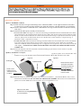
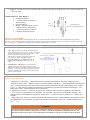
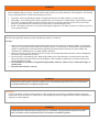
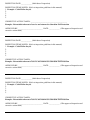
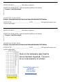
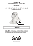
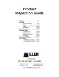
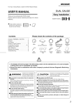
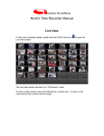
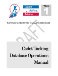
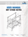
Guardian Fall Protection Kent WA 98032 800.466.6385 www.guardianfall.com GENERAL SYSTEM SELECTION CRITERIA: Selection of fall protection shall be made by a Competent Person. All fall protection equipment shall be purchased new and unused. The equipment is designed for use as a part of a personal fall protection system. Components shall not be used for any other operation other than that which it has been designed and approved. Fall Arrest Systems shall be designed to comply with OSHA or applicable state regulatory limitations. Systems must be used in a compliant manner. Fall Restraint systems shall be designed by a Qualified Person, and must be installed and used under the supervision of a competent person. PART T NUMBERS: ______ 10974 50ft. 3-Way Retractable ______ 10981 65ft. 3-Way Retractable Retractables DO NOT THROW AWAY THESE INSTRUCTIONS! READ AND UNDERSTAND BEFORE USING EQUIPMENT! This manual should be read and understood in its entirety, and used as part of a training program as required by OSHA or any applicable state regulatory agency. This and any other included instructions must be provided to the users of the equipment. The user must understand the proper equipment use and limitations. User must keep a copy of these instructions for reference and training. Consult a doctor if there is any reason to doubt a user’s ability to withstand and safely absorb fall arrest forces. Age, fitness, and health conditions can seriously affect the worker should a fall occur. Pregnant women and minors should not use this equipment. WARNING! DO NOT: x Do not alter or misuse this equipment. x Do not use combinations of components or subsystems that may affect or interfere with the safe, compatible function of each other. x Do not expose the equipment to chemicals which may produce a harmful effect or degrade the equipment. Consult manufacturer in cases where doubt exists. x Do not use the equipment around moving machinery or electrical hazards unless specifically designed for such use. x Do not use the equipment around sharp edges or abrasive surfaces unless intended for such use. This product meets all applicable OSHA and ANSI standards for fall protection. TRAINING REQUIREMENTS: The employer shall provide a training program for each employee who might be exposed to fall hazards. The program shall enable each employee to recognize the hazards of falling and shall train each employee in the procedures to be followed in order to minimize these hazards. Relevant Federal, State, and local regulatory requirements, procedures, and standards shall also be a part of training. The employer shall ensure that each employee has been trained, as necessary, by a Competent or Qualified Person in the nature of fall hazards in the work area, the correct erecting, maintaining, disassembling, and inspection of the fall protection systems being used, and the use of personal fall arrest systems. RESCUE PLAN: The user is required to have a rescue plan and the means at hand to implement it when using the equipment. The plan shall be project specific. Employees shall be trained in self-rescue or alternate means shall be provided for prompt rescue in the event of a fall. IF EQUIPMENT IS SUBJECTED TO A FALL: Remove the equipment from service immediately if it has been subjected to the forces of a fall arrest. Contact your distributor or Guardian about policies regarding replacement of Guardian components involved in a fall. INSPECTION: x x x Only the manufacturer of this equipment or persons or entities authorized in writing by the manufacturer shall make repairs to fall protection equipment. The date of first inspection should be recorded by the employer on the equipment, and any serial numbers shall be recorded on the Inspection Log. Formal inspections shall be made by either a Competent or Qualified Person on at least a semi-annual basis. PRIOR TO EACH USE: x x x Fall protection equipment shall be inspected by the user for defects, damage, or deterioration. Any suspected defective equipment shall be removed from service. If the manufacturer’s label is not legible or is missing, the equipment shall be removed from service. Fall protection equipment shall be removed from service upon evidence of defects, damage, or deterioration, or upon expiration of the manufacturer’s specified service limits, whichever comes first. WARNING! OPERATION AND USE: Option 1) Installation overhead: Step 1: Attach retractable to an approved anchorage able to withstand 5,000lbs. Use the supplied carabineer and connect it to the swivel eye on the top of the retractable. Now attach the carabineer, with SRL attached, to your anchorage. Step 2: Check to insure that the crank handle on the 3-WAY SRL has free range of motion and does not interfere with any other object. Step 3: Check that the SRL operates smoothly in both directions. x To Lower the Cable: Pull (Figure A.) outward on the locking pin and hold. Rotate the ratchet handle until it slides outward and stops in the engaged position. Release the pin so that it falls into the locking position. Rotate the crank handle in counter clockwise direction. If a fall has been arrested and lowering is required, first crank in the upward, clockwise, direction for one half rotation. Now reverse the direction, counter clockwise, to begin lowering. A minimum of 75lbs is required for lowering. x To Raise the Cable: Pull outward on the locking pin and hold. Rotate the ratchet handle until it slides outward and stops in the engaged position. Release the pin so that it falls into the locking position. Rotate the crank handle clockwise to crank the cable into the housing. Note: to engage the recovery system, it may be necessary to rotate the crank slightly. **CHECK THAT THE RATCHET HANDLE ENGAGES AND OPERATES THE WINCH CORRECTLY. Step end of the retractable to the dorsal D-Ringg of your harness. Do not connect to any other p 4: Attach the snaphook ph y connection point on the harness. Option on 2) Installation to a Tripod: Step 1: Attach the 3-WAY SRL to the 3-WAY Tripod Bracket by first removi removing ving the two plastic screws scr from the SRL. Then hook on the bracket and then slide the 3-WAY cradle. slide the swivel eye into the ho 3-W -WAY SRL into the bracket br Figure A. Figure B. Locking Pin Ratchet Handle Plastic stic screw: Remove move one on each ch side in same location. ation. Notice how the swivel eye hooks around the end of the bracket. You must attach this end retractable downward into the cradle. Step 2: Once the 3-WAY is cradled in tthe bracket, insert the two screws that are These screws a supplied with the bracket. b SRL. DO NOT USE THE PLASTIC SCREWS. These holes fasten into the standoff in the SR S hole are located under the plastic screws on the handle side of the retractable. Do not overtighten the screws. Tighten screws down on both sides ensuring to not overtighten. Step 3: Attach the 3-WAY SRL and Bracket assembly to the tripod leg that contains the pulley on the top of the tripod. Only install the 3-WAY BRAC T to the outside of the leg There are two options for installing the 3-WAY SRL to the retractable leg based on how high you have adjusted the tripod. Installation shows the 3-WAY bracket attached to the larger diameter of the tripod leg. Note the . pin configuration. This is used when the tripod is at full e tension. Installation shows the tripod at a lowered height. These different attachment points will allow you to adjust the 3-WAY SRL to your desired height for handle clearance when lifting a worker. Ta e note o where the pins atta h to the tripod le . When pinnin the bra et a ainst the s aller dia eter le o st se the thro h hole whi h is losest to the le to se re the bra et. Installation Pin Installation Pin Pin Pin pulley. You will need to remove the detent pin, shown in Step 4: Run the snaphook from the SRL up and over the pu through the pulley and down through the center opening as Figure A, over the pulley to maneuver the cable thro pulley, the detent pin. shown in Figure A. Once cable is run over the pulley pu ey replace pl p Your assembled unit should look like Figure B. Figure B. Detent Pin Step : Refer to step 3 and from Option on page age . x Capa it : The SRL is for use by one person with a combined weight (person, clothing, tools, etc.) of 75lbs. minimum and 3 0lbs. ma imum. Consider When Cal latin Distan e: x Deceleration Distance x ovement of harness attachment element (D-ring) x Free Fall Distance x Worker eight (how tall the worker is could affect the free fall distance) x levation of Anchorage Connector x Connecting Subsystems Length Feet a Free Fall Total Fall Distance (Free Fall Deceleration Distance) APPLICA LE STANDARDS: Refer to potential applicable standards. Standards might include OS A regulations depending on the type of work, and also might include state regulations if applicable. Consult regulatory agencies for more information on personal fall arrest systems and associated components. This product is designed to comply with OS A and ANSI 35 . standards when used properly, and in accordance with manufacturer s instructions. LI ITATIONS CONTINUED: x Swin alls: Swing falls occur when the anchorage point is not directly above the point where a fall occurs. The force of striking an object in a swing fall may cause serious injury or death. inimi e the risk of swing falls by working as close to the ATTACH TO O ERHEAD anchorage point as possible. Do not permit a swing fall if ANCHORS! injury could occur. Swin alls will si ni i antl SWING ALLS INCREASE in rease the learan e re ired when a sel retra tin ALL ARREST DISTANCE. li eline or other variable len th onne tin s ste is sed. x Potential Environ ental Ha ards: Use of fall protection equipment in areas with environmental ha ards may require additional precautions to prevent injury to the user or damage to the equipment. a ards may include but are not limited to: chemicals, corrosive environments, high voltage power lines, gases, moving machinery, and sharp edges. SYSTE x x x RE UIRE ENTS: Compatibility of Components: uardian Fall Protection equipment is designed to be used with uardian approved components. Please contact uardian if you have a question regarding compatibility. aking substitutions without approval from uardian Fall Protection may lead to injuries and or death by compromising the safety and reliability of the complete system. A ualified person can make a determination on compatibility of equipment from different manufacturers. If in doubt, please contact uardian Fall Protection for clarification. Compatibility of Connectors: Connectors (D-rings, hooks, carabiners) must be capable of supporting at least 5,000 lbs. ( kN). Do not use equipment that is not compatible. Non-compatible connectors may unintentionally disengage. Self locking snap hooks and carabiners are required by ANSI and OS A. Connectors must be compatible in si e, shape, and strength. aking Connections: Only use self-locking snap hooks and carabiners with any uardian Fall Protection equipment. Do not use equipment that is not compatible. If you have any questions on compatibility, please call uardian Fall Protection at 00. . 3 5. WARNING! Large throat opening snap hooks should not be connected to standard si e D-rings or similar objects which will result in a load on the gate if the hook or D-ring twists or rotates. Large throat snap hooks are designed for use on fi ed structural elements such as rebar or cross members that are not shaped in a way that can capture the gate of the hook. PERSONAL ALL ARREST IN OR ATION: x Personal all Arrest S ste P AS): Personal fall arrest systems used with this equipment must meet applicable state, federal, OS A, and ANSI requirements. A full body harness must be worn when this equipment is used as a component of a personal fall arrest system. As required by OS A, the personal fall arrest system must be capable of arresting the user s fall with a ma imum arresting force of , 00 lbs., and limit the free fall to si feet or less. WARNING! Do not alter or intentionally misuse this equipment. Consult with FP when using this equipment in combination with components or subsystems other than those described here in this manual and or other information. Use caution when using this equipment around moving machinery, electrical and chemical ha ards, and sharp edges. LI ITATIONS: Consider the following application limitations before using this equipment. x x x x x Capa it : The SRL is to be used by an individual with a combined weight (person, clothing, tools, etc.) of 75 pounds minimum and no more than 3 0lbs ma imum. No more than one person may be connected at one time. Corrosion: Leaving the SRL in an environment for long periods of time that could cause corrosion of metal parts is not warranted in any way and must not be done. Use caution when working around corrosive compounds such as ammonia, sewage, fertili ers, seawater or other corrosive environments, may require more frequent inspections or servicing. These increased inspections and servicing are required to ensure corrosive damage is not impacting the performance of the SRL. Che i al Ha ards and Heat: treme caution must be taken when working in or around environments containing acid or caustic chemicals, particularly at elevated temperatures. Damage will result to FP SRL s in this environment. Chemical damage is difficult to detect and it is recommended that the lifeline be replaced periodically to ensure safety of the workers. Additionally, this SRL is not to be used in high temperature environments. The SRL must be protected when using near welding, metal cutting, or similar activities. ot sparks and slag can damage this equipment. Users must inspect SRL prior to each use. Ele tri al Ha ards: For web and wire rope models, there is a possibility of an electric current flowing through the lifeline. oisture absorbed by the lifeline may provide a path for electrical current to flow, resulting in electrical shock. Use caution where the lifeline may contact high voltage power lines. Lo in Speed: treme caution should be taken when using this device whereas an obstructed fall could occur as well as when someone must perform work in a confined or cramped space. Working in these types of environments could limit the speed at which the locking mechanisms engage. A clear path is required to ensure positive locking of the SRL. DESCRIPTION O PRODUCT: Retra table: All uardian Retractables are to be considered a mechanical device or a Self-Locking Anchorage Device , or a Self Retracting Lifeline (SRL). This device is used to safely e pand the working area where a harness with a ft. lanyard is not adequate. Also, a SRL is designed to reduce the shock loading to the body of a worker by limiting the distance of a fall. The device allows for complete freedom of movement. The SRL is to be considered part of a personal fall arrest system. The SRL is to be used as part of a complete fall arrest system. PFAS normally include the use of a full body harnees, anchorage connector such as a carabiner and the SRL. GUARDIAN 3 WAY SEL RETRACTING LI ELINE: Includes 3-WAY retractable, 5ft tagline and double locking carabineer. The SRL 3-WAY also includes a swivel, locking, fall indicating snaphook. PRODUCT APPLICATION IN OR ATION: The SRL 3-WAY is used in a stationary manner. As a stationary device, the SRL would be mounted to an approved fi ed anchorage connector directly overhead. Applications of an approved anchor include mounting to the uardian Fall Protection 0 0 Arco-Pod using the 0 3 3-WAY Bracket. The 3-WAY retractable can also be attached to a retractable using the static anchor points at the peak of the tripod. INSPECTION O SEL RETRACTING LI ELINES: WARNING! If inspection reveals an unsafe or defective condition, remove the product from service and send product back to uardian Fall Protection or a FP authori ed service center. x e ore ea h se o this e ip ent inspe t it a ordin to the ollowin idelines: A formal inspection of fall protection products components must be performed at least every si months by a competent person other than the user. The frequency of formal inspections should be based on conditions of use or e posure. Record the inspection results in the inspection and maintenance log at the end of this manual. OS A 0. , OS A .50 and ANSI 35 . requires an inspection of equipment before each use. Before using this equipment, record the serial number information from the label in the inspection and maintenance log at the end of this manual. x x Ann all : ANSI requires a formal inspection of the SRL be completed by a competent person other than the user at least twice a year. ore formal and frequent inspections maybe required based upon the severity and environmental conditions of the workplace. uardian Fall Protection Retractables, unless otherwise marked, are required to be recertified every two years from the date of first use. A ter a all Arrest: Inspect the impact indicator on the snap hook of the SRL and look for an e posed red color band. Do not attempt to reset the impact indicator. Remove the retractable from service immediately and return to uardian or an authori ed repair center. If using a retractable with a webbed lifeline, then inspection of the shock pack is required. Remove retractable from service if there are any deformation, elongation or other signs of the shock pack being torn or deployed. If inspection reveals an unsafe condition, remove unit from service immediately and destroy, or contact an authori ed service center for repair. Inspe tin the SEL RETRACTING LI ELINES: Step 1. Step 2. Step 3. Step 4. Step . Step . Step . Step . Step . Step 1 . Inspect for loose screws and bent or damaged parts. Inspect housing for distortion, cracks or other damage. nsure the swivel eye is not damaged or distorted in anyway. ake sure the swivel eye turns freely. The lifeline must fully e tend and retract without hesitation or creating a slack line condition. nsure the device locks up when lifeline is jerked sharply. The labels must be present and fully legible with inspection log information completed. Look for signs of corrosion on the entire unit. Wire rope inspection must include identifying cuts, kinks, broken wires, bird-caging, corrosion, welding splatter, chemical damage, or severely abraded areas. Check all thimbles etc for e cessive wear including cracks or separation of metal components. ngage the crank handle and check that it lowers and raises without hesitation. Apply a load to the line and insure that the braking mechanism holds without slippage greater than two ( ) inches. Inspect connecting hooks or carabiners for signs of damage, corrosion or e cessive wear. Record inspection results in the inspection and maintenance log found in this manual. Clearly check off month the SRL was inspected on the label of the housing. WARNING! CA LE INSPECTION: When inspecting SRL s that utili e cable lifelines, it is critical to look for the following damages and deterioration that will result in malfunction of the unit and potentially unsafe conditions. Cr shin : The cable will often get crushed or bent while being used on a job site. Cable that is crushed or bent will damage the retractable and thus the unit should be immediately taken out of service and returned to uardian or an authori ed repair center. C ttin : ovement over sharp edges or other objects while the cable is under tension can result in damaged strands and broken wires. If, through inspection of the retractable lifeline prior to each use, it is found to have any broken strands, immediately remove from service and return to uardian or an authori ed repair center. Abrasion: Abrasion can result from normal wear. Particular attention must be paid to the outer wire strands as they will appear to be flattened and or shiner than other parts of the cable. If, through inspection of the retractable lifeline prior to each use, it is found have damage or deterioration from abrasion, immediately remove from service and return to uardian or an authori ed repair center. Kin in : Any deformation in the cable whereas the lifeline appears to be bent, requires the retractable to be immediately removed from service and returned to uardian or an authori ed repair center. Corrosion Ar or Heat Da a e: treme caution must be taken to avoid any potential damage as a result of using a retractable within an environment where corrosive compounds, welding, or high heat may e ist. Corrosive damage could cause the cable to crack. Welding damage would result in fused wires and thus change the characteristics of the strength with regards to the wire. If the retractable is used in these environments, the retractable lifeline needs to be closely e amined for damage. If you have any questions in terms of damage to the retractable or further e planation of the above information is needed, please call - 00- - 3 5. WARNING! PLAN THE FALL PROTECTION SYSTEM: Before installation plan your system. Consider all factors that will affect your safety during use of this equipment. The following list gives important points to consider when planning your system: Anchorage: Select a rigid anchorage capable of supporting the loads no less than 5,000 lbs. per worker attached. Sharp Edges: Avoid working where system components may be in contact with, or abrade against, unprotected sharp edges. After a Fall: Components which have been subjected to the forces of arresting a fall must be removed from service and destroyed. Retractable must be returned for servicing to GFP or an authorized repair center. Rescue: The employer must have a rescue plan when using this equipment. The employer must have the ability to perform a rescue quickly and safely. INSTALLATION REQUIREMENTS: The following requirements outline the proper installation procedures to be followed. Location: Select a location on an appropriate strength anchorage that will provide overall safety and proper loading. The anchorage must be free of deformities or defects that may weaken the structure. The anchorage to which the SRL is attached must be capable of sustaining static loads in the directions applied by the personal fall arrest systems of at least 3,600lbs with certification of a qualified person, or 5,000lbs without certification. When more than one person is attached to the same structure, the strength requirements stated above must be multiplied by the number of personal fall arrest systems. Do not work above the anchorage point. While using an SRL, always ensure that there is constant tension on the cable. Slack in the cable could result in an increase in fall distance. Move normally as sudden jerky movements will allow the locking mechanism to engage. Do not install in an area where a swing fall hazard potentially could exist. Failure to do so could result in injury or possibly death. Keep these instructions for reference. WARNING! If inspection reveals an unsafe or defective condition, remove the Self Retracting Lifeline from service and send back to Guardian Fall Protection or an authorized repair center. TRAINING: It is the responsibility of the user and the purchaser of this equipment to assure that they are familiar with these instructions, trained in the correct care and use of, and are aware of the operating characteristics, application limits, and the consequences of improper use of this equipment. WARNING! Training should be conducted without exposing anyone to a fall hazard. Training should be repeated on a periodic basis in accordance with your organizations policy and compliance with OSHA regulations. 50ft. to 65ft. Cable Rescue & Retrieval Retractable (10974/10981) Serial NO. 6000 Man. Date 50’; 3/16” CABLE 65’; 3/16” CABLE 10974 10981 WARNING: Manufacturer’s instructions supplied with this product at time of shipment must be followed for proper use, maintenance and inspection. Alterations or misuse of this product or failure to follow the instructions may result in serious injury or death. DO NOT ATTEMPT TO SELF SERVICE OR REPAIR EE-WAY R RACTABLE ARDIAN T ET HR INSPECTION: Inspect unit in accordance to the manufacturer’s instruction manual and regulatory guidelines. Before use inspect for any signs of damage, wear or malfunctioning components. Check lifeline retraction by pulling out a minimum 4 ft. of lifeline and allowing it to retract under light tension, lifeline should retract completely. Pull sharply to test locking function, brakes must engage. Before use, inspect the lifeline condition, function and condition of fasteners, and legibility of labels. Also, check for evidence of defects, damage, or missing parts. Depending on model, user must inspect the shock pack for signs of deployment, or impact indicator for signs of activation. Device must be taken out of service for inspection and recertification after arresting a fall, or if either the shock pack or impact indicator (depending on model) show signs of activation. Do not use if inspection reveals an unsafe condition. Unit must be inspected by a trained and competent person at least monthly. Unit must be recertified every 2 years, from date of first use, by the manufacturer or authorized repair center. GU 3-WAY RETRACTABLE USE: Always use in accordance with manufacturer’s instruction manual and labels included with this device at the time of shipment. This device is only for use by one person as a fall arrester. Always connect the snap hook directly to the attachment point on the safety harness. Guard against swing-falls by keeping the lifeline vertically overhead. Never work above the device. Allow 42” free fall space below the work area. Do not allow the lifeline to become slack, and maintain tension while letting it retract after disconnecting from worker. Do not allow lifeline to come in contact with anything that will damage it including but not limited to sharp edges, rough or high temperature surfaces, welding, heat sources, electrical hazards, or moving machinery. Ensure that connection to anchorage is secured properly before use. This unit is for use by trained persons only. See user manual for more details. SPECIFICATIONS: Maximum arresting distance: 42in. (3ft.6in.) Maximum arresting force: 900 lbs Maximum capacity: 310 lbs RECOVERY SYSTEM OPERATION: Pull outward on the locking pin and hold. Pull outward on the ratchet handle until it stops. Release the pin so that it falls into the locking position. While maintaining outward tension on the cable, rotate the crank handle clockwise (cw) to crank the cable into the housing. Note: to engage the recovery system it may be necessary to rotate the crank slightly. FOR LOWERING: Rotate crank handle in counter clockwise (ccw) direction. If a fall has been arrested and lowering is required, first crank in the upward direction (cw) for one half rotation, then reverse the direction (ccw) to begin lowering. A minimum of 75 lbs (34kg) is required for lowering. J F M A M J J A S O N D YR YR YR YR YR Date of first use www.guardianfall.com Made in U.S.A. MADE IN U.S.A. OSHA 1926.502, 1910.66 ANSI Z359.1 - 2007 INSPECTION AND MAINTENANCE LOG: *ALL EDGE RETRACTABLES, EXCLUDING THE 11FT. WEB UNIT, MUST BE SERVICED EVERY TWO YEARS FROM DATE OF FIRST USE. 11FT. WEB RETRACTABLE MUST BE INSPECTED EVERYDAY AS ANY OTHER RETRACTABLE DEVICE. SERIAL NUMBER:______________________(Log unit serial number found on backside of label) MODEL NUMBER:______________________(Model number found on backside of label) DATE PURCHASED:______________________ DATE OF FIRST USE:____________________ INSPECTION DATE:____________ (Mark date of inspection) INSPECTION ITEMS NOTED: (Refer to inspection guidelines in this manual) 1. Example: Cable lifeline frayed. 2. 3. 4. 5. CORRECTIVE ACTION TAKEN: _________________________________________ Example: Retractable taken out of service and returned to Guardian Fall Protection APPROVED BY:____________________________ DATE: ____________ (Who approved inspection and corrective action taken) INSPECTION DATE:____________ (Mark date of inspection) INSPECTION ITEMS NOTED: (Refer to inspection guidelines in this manual) 1. Example: Cable lifeline frayed. 2. 3. 4. 5. CORRECTIVE ACTION TAKEN: _________________________________________ Example: Retractable taken out of service and returned to Guardian Fall Protection APPROVED BY:____________________________ DATE: ____________ (Who approved inspection and corrective action taken) INSPECTION DATE:____________ (Mark date of inspection) INSPECTION ITEMS NOTED: (Refer to inspection guidelines in this manual) 1. Example: Cable lifeline frayed. 2. 3. 4. 5. CORRECTIVE ACTION TAKEN: _________________________________________ Example: Retractable taken out of service and returned to Guardian Fall Protection APPROVED BY:____________________________ DATE: ____________ (Who approved inspection and corrective action taken) INSPECTION DATE:____________ (Mark date of inspection) INSPECTION ITEMS NOTED: (Refer to inspection guidelines in this manual) 1. Example: Cable lifeline frayed. 2. 3. 4. 5. CORRECTIVE ACTION TAKEN: _________________________________________ Example: Retractable taken out of service and returned to Guardian Fall Protection APPROVED BY:____________________________ DATE: ____________ (Who approved inspection and corrective action taken) INSPECTION DATE:____________ (Mark date of inspection) INSPECTION ITEMS NOTED: (Refer to inspection guidelines in this manual) 1. Example: Cable lifeline frayed. 2. 3. 4. 5. CORRECTIVE ACTION TAKEN: _________________________________________ Example: Retractable taken out of service and returned to Guardian Fall Protection APPROVED BY:____________________________ DATE: ____________ (Who approved inspection and corrective action taken) INSPECTION DATE:____________ (Mark date of inspection) INSPECTION ITEMS NOTED: (Refer to inspection guidelines in this manual) 1. Example: Cable lifeline frayed. 2. 3. 4. 5. CORRECTIVE ACTION TAKEN: _________________________________________ Example: Retractable taken out of service and returned to Guardian Fall Protection APPROVED BY:____________________________ DATE: ____________ (Who approved inspection and corrective action taken) INSPECTION DATE:____________ (Mark date of inspection) INSPECTION ITEMS NOTED: (Refer to inspection guidelines in this manual) 1. Example: Cable lifeline frayed. 2. 3. 4. 5. CORRECTIVE ACTION TAKEN: _________________________________________ Example: Retractable taken out of service and returned to Guardian Fall Protection APPROVED BY:____________________________ DATE: ____________ (Who approved inspection and corrective action taken) INSPECTION DATE:____________ (Mark date of inspection) INSPECTION ITEMS NOTED: (Refer to inspection guidelines in this manual) 1. Example: Cable lifeline frayed. 2. 3. 4. 5. CORRECTIVE ACTION TAKEN: _________________________________________ Example: Retractable taken out of service and returned to Guardian Fall Protection APPROVED BY:____________________________ DATE: ____________ (Who approved inspection and corrective action taken) INSPECTION DATE:____________ (Mark date of inspection) INSPECTION ITEMS NOTED: (Refer to inspection guidelines in this manual) 1. Example: Cable lifeline frayed. 2. 3. 4. 5. CORRECTIVE ACTION TAKEN: _________________________________________ Example: Retractable taken out of service and returned to Guardian Fall Protection APPROVED BY:____________________________ DATE: ____________ (Who approved inspection and corrective action taken) INSPECTION DATE:____________ (Mark date of inspection) INSPECTION ITEMS NOTED: (Refer to inspection guidelines in this manual) 1. Example: Cable lifeline frayed. 2. 3. 4. 5. CORRECTIVE ACTION TAKEN: _________________________________________ Example: Retractable taken out of service and returned to Guardian Fall Protection APPROVED BY:____________________________ DATE: ____________ (Who approved inspection and corrective action taken) INSPECTION DATE:____________ (Mark date of inspection) INSPECTION ITEMS NOTED: (Refer to inspection guidelines in this manual) 1. Example: Cable lifeline frayed. 2. 3. 4. 5. CORRECTIVE ACTION TAKEN: _________________________________________ Example: Retractable taken out of service and returned to Guardian Fall Protection APPROVED BY:____________________________ DATE: ____________ (Who approved inspection and corrective action taken) INSPECTION DATE:____________ (Mark date of inspection) INSPECTION ITEMS NOTED: (Refer to inspection guidelines in this manual) 1. Example: Cable lifeline frayed. 2. 3. 4. 5. CORRECTIVE ACTION TAKEN: _________________________________________ Example: Retractable taken out of service and returned to Guardian Fall Protection APPROVED BY:____________________________ DATE: ____________ (Who approved inspection and corrective action taken) INSPECTION DATE:____________ (Mark date of inspection) INSPECTION ITEMS NOTED: (Refer to inspection guidelines in this manual) 1. Example: Cable lifeline frayed. 2. 3. 4. 5. CORRECTIVE ACTION TAKEN: _________________________________________ Example: Retractable taken out of service and returned to Guardian Fall Protection APPROVED BY:____________________________ DATE: ____________ (Who approved inspection and corrective action taken) Mark on the retractable label that the device has been inspected. Failure to do so voids warranty of product. Guardian Fall Protection, Inc. 800.466.6385 26609 79th Ave. S. Kent, WA 98032 www.guardianfall.com