1
USER’S MANUAL
MITSUBISHI HEAVY INDUSTRIES LTD. PACKAGED AIR CONDITIONER
USER’S MANUAL
ENGLISH
MANUEL DE L’UTILISATEUR
FRANCAIS
¸
ANWENDERHANDBUCH
DEUTSCH
ISTRUZIONI PER L’USO
ITALIANO
MANUAL DEL PROPIETARIO
ESPAÑOL
GEBRUIKERSHANDLEIDING
NEDERLANDS
MANUAL DO UTILIZADOR
PORTUGUÊS
√¢∏°π∂™ Ã∏™∏™
∂§§∏¡π∫∞
РУКОВОДСТВО ПО ЭКСПЛУАТАЦИИ
РУССКИЙ
KULLANIM KILAVUZU
ESPAÑOL
TÜRKÇE
MULTI-SERIES
AIR-CONDITIONING & REFRIGERATION SYSTEMS HEADQUARTERS
3-1, Asahi, Nishibiwajima-cho, Kiyosu, Aichi, 452-8561, Japan
Ceiling Recessed Type (FDT, FDTC)
Ceiling Recessed Type, 2-Way Air Direction (FDTW)
Ceiling Recessed Type, 1-Way Air Direction (FDTS) (FDTQ)
Ceiling Recessed Cassetteria Type (FDR)
High Static Pressure Duct Type (FDU)
Middle Static Pressure Duct Type (FDUM) (FDQM)
Ceiling mounted duct Type (FDUR)
Ceiling Suspended Type (FDE)
Wall Mounted Type (FDK)
Floor Standing, Lowboy Type (Exposed Type) (FDFL)
Floor Standing, Lowboy Type (Concealed Type) (FDFU)
Ultra thin ducted Type (FDQS)
MITSUBISHI HEAVY INDUSTRIES EUROPE, LTD.
AIR-CONDITIONER DIVISION
3rd Floor Thavies Inn House 3-4 Holborn Circus London EC1N 2HA, ENGLAND
Phone: 44(0)20 7842 8171
Fax: 44(0)20 7842 8104
MITSUBISHI HEAVY INDUSTRIES AUSTRALIA, PTY.LTD.
81 Railway Street, Rockdale, NSW 2216, Australia
Phone: 61(0)2 9597 7977
Fax: 61(0)2 9597 7304
MITSUBISHI HEAVY INDUSTRIES-MAHAJAK AIR CONDITIONERS CO.,LTD.
200 Moo 4, Lat Krabang Industrial Estate Phase 3, Chalongkrung Road,
Lamplatlew, Lat Krabang, Bangkok 10520, Thailand
Phone: 662 326 0401
Fax: 662 326 0419
This air conditioner complies with EMC Directive 89/336/EEC,
92/31/EEC, 93/68/EEC, LV Directive 73/23/EEC.
CE marking is applicable to the area of 50 Hz power supply.
Dieses Kimagerät erfüllt die EMC Direktiven 89/336/EEC, 92/
31/EEC, 93/68/EEC, LV Direktiven 73/23/EEC.
Die CE-Marke gilt für Bereiche mit einer Netzstromversorgung
von 50 Hz.
Este acondicionador de aire cumple con la directiva EMC: 89/
336/EEC, 92/31/EEC, 93/68/EEC, LV Directiva 73/23/EEC.
La indicación CE sólo corresponde al área de suministro
eléctrico de 50 Hz.
Este aparelho de ar condicionado está em conformidade com
a Directiva EMC 89/336/CEE, 92/31/CEE, 93/68/CEE, a
Directiva LV 73/23/CEE.
A marca CE aplica-se à zona de fornecimento de energia a
50 Hz.
Ce climatiseur est conforme à la Directive EMC: 89/336/EEC,
92/31/EEC, 93/68/EEC, LV Directive 73/23/EEC.
La marque CE s’applique aux régions alimentées en courant
de 50 Hz.
Questo condizionatore d’aria è conforme alla Direttiva EMC:
89/336/EEC, 92/31/EEC, 93/68/EEC, LV Direttiva 73/23/EEC.
Il marchio CE è applicabile alla fascia di alimentazione 50 Hz.
Deze airconditioner voldoet aan EMC Directive 89/336/EEC,
92/31/EEC, 93/68/EEC, LV Directive 73/23/EEC.
CE-markering is van toepassing op het gebied met een
netstroom van 50 Hz.
∞˘Ùfi ÙÔ ÎÏÈÌ·ÙÈÛÙÈÎfi Â›Ó·È Û‡ÌʈÓÔ Ì ÙȘ ÚԉȷÁڷʤ˜
ÙˆÓ √‰ËÁÈÒÓ EMC 89/336, 92/31 Î·È 93/68 Ù˘ ∂√∫ ηÈ
Ù˘ √‰ËÁ›·˜ LV 73/23 Ù˘ ∂√∫ .
∆Ô Û‹Ì· CE ÈÛ¯‡ÂÈ ÌfiÓÔÓ Û ÂÚÈÔ¯¤˜ fiÔ˘ Ë
ÙÚÔÊÔ‰ÔÛ›· Â›Ó·È 50 Hz.
PCA012A001
PCA012A001L_Cover
1
07.3.13, 11:03
L
Thank you very much for your purchase of this package air conditioning system made
by Mitsubishi Heavy Industries. Please read through this manual before using the product and use the product appropriately according to the instructions in the manual. After
you have read the manual, store it with the warranty certificate in a safe place. It will
help you when you have questions or problems.
TABLE OF CONTENTS
SAFETY PRECAUTIONS
● Please read these “SAFETY PRECAUTIONS” before starting to use this product and use the product appropriately according to the
instructions.
● The precautions provided here are classified into “ DANGER” and “ CAUTION” Potentially hazardous situations that may lead to
serious outcomes such as death and serious injuries if the product is mishandled, in particular, are grouped together and described in
the “ DANGER” sections. Note, however, that depending on the situation, the items listed in the “ CAUTION” sections do also have
the potential of causing serious outcomes. Both warnings and cautions tell you important information related to safety; please make
sure to observe them.
● The symbols used throughout the main text of this manual have the following meaning:
Observe instructions with
great care.
Strictly prohibited.
■ SAFETY PRECAUTIONS .................................................................................................................. 1
■ NAMES AND FUNCTIONS OF THE REMOTE CONTROLLER SWITCHES ................................... 3
■ HOW TO USE THE AIR CONDITIONING SYSTEM ......................................................................... 3
Provide positive earthing.
● After you have read the manual, always store it at a place where other users of the system can refer to it at any time. If a new owner
takes over the system, make sure to pass this manual to that person.
❚ INSTALLATION PRECAUTIONS
HOW TO OPERATE THE AIR CONDITIONING SYSTEM ............................................................... 3
DANGER
HOW TO PERFORM THE TIMER OPERATION .............................................................................. 4
SELECTING TIMER MODES ......................................................................................................... 4
Make sure to request the dealer from whom you have purchased the product or a specialist to install the product.
Make sure to use accessories specified by Mitsubishi Heavy
Industries. Request a specialist to install them.
If you install the product by yourself and the product is not correctly installed,
water leakage, electric shock and/or fire may occur.
If you install the accessories by yourself and the accessories are not correctly
installed, water leakage, electric shock and/or fire may occur.
ADJUSTING THE TIME .................................................................................................................. 5
SLEEP TIMER MODE..................................................................................................................... 5
OFF TIMER MODE ......................................................................................................................... 6
ON TIMER MODE ........................................................................................................................... 6
WEEKLY TIMER MODE ................................................................................................................. 7
TIMER CANCELLATION MODE .................................................................................................... 12
HOW TO OPERATE IN SILENT MODE ............................................................................................ 13
SILENT MODE ................................................................................................................................ 13
HOW TO ADJUST THE AIRFLOW DIRECTION ............................................................................... 14
If the refrigerant leaks and the critical concentration is
exceeded, accidents may occur due to oxygen deficiency.
Moreover, if the refrigerant gets into contact with flames, for
instance from a fan heater, space heater, cooking stove, toxic
gases may be generated. If the refrigerant is found to be
leaking, extinguish any flames in the room and ventilate the
room.
AIRFLOW ADJUSTMENT BY THE LOUVER SWITCH (FOR INDOOR UNITS WITH THE AUTO SWING FUNCTION) ...... 14
VENTILATION MODE OPERATION (WHEN A VENTILATOR IS INSTALLED) .............................. 14
USING THE AIR CONDITIONING SYSTEM IN A COMFORTABLE MANNER ............................... 14
HOW TO MAINTAIN THE AIR CONDITIONING SYSTEM ............................................................... 15
■ TROUBLESHOOTING ....................................................................................................................... 16
ABOUT INSPECTION DISPLAY, FILTER MESSAGE DISPLAY, AIR CONDITIONING NUMBER AND OPERATION STANDBY DISPLAY ....... 17
CAUTION
Make sure to perform grounding work.
It is necessary to install a leakage
breaker.
Do not install the air conditioning system
in a place where there is any possibility
that combustible gas may leak.
Do not connect the ground wire to a ground wire
connected to any gas pipes, water pipes, lightning
conductors or telephones. Incomplete grounding
may cause electric shock.
If a leakage breaker is not installed, electric
shock may happen.
If such gas leaks and accumulates around the unit,
the gas may catch fire.
Make sure to construct the drain piping
so that water is securely discharged.
Construct the system in such a way as
to prevent parts from being overturned
in areas subjected to the effects of
strong wind.
Install the air conditioning system
securely in a place that can stand the
weight of it.
If the piping construction is inadequate, water may
leak and wet household goods.
Strong wind may overturn an outdoor unit,
leading to injury.
If the installation is inadequate, the unit may
overturn or fall down, leading to injury.
WHEN THE CHECK INDICATOR LIGHT (RED) FLASHES .......................................................... 17
WHEN THE FILTER CLEANING MESSAGE IS DISPLAYED ....................................................... 17
HOW TO DISPLAY AIR CONDITIONING UNIT NO. ..................................................................... 17
ABOUT OPERATION STANDBY DISPLAY ................................................................................... 17
ABOUT PREPARATION OF HEATING ............................................................................................. 18
CASES WHEN “
” (PREPARATION OF HEATING) IS DISPLAYED ................... 18
ABOUT HEATING OPERATION .................................................................................................... 18
ABOUT POWER FAILURE COMPENSATION ................................................................................. 18
ABOUT SETTING TO DISABLE SWITCH OPERATION .................................................................. 18
ABOUT INSTALLATION, MOVING AND INSPECTION MAINTENANCE ........................................ 18
INSTALLATION LOCATION ........................................................................................................... 18
ELECTRICAL WORK ...................................................................................................................... 18
AT MOVING .................................................................................................................................... 18
ABOUT INSPECTION MAINTENANCE ......................................................................................... 18
OPERATION RANGE ..................................................................................................................... 18
1
PCA012A001H_E_P01
1
05.11.16, 12:14
ENGLISH
SAFETY PRECAUTIONS
SAFETY PRECAUTIONS
❚ OPERATION PRECAUTIONS
CAUTION
DANGER
Do not subject your body to cooled air
for a prolonged period or cool it too
much.
Do not insert fingers and/or other
elongated devices in the air outlet and
inlet openings.
Do not sit on the air conditioning system
or place objects on it.
Do not allow combustible spray near
the air conditioning system, nor spray
it directly to the air conditioning
system.
Do not use the air conditioning system
with the outlet/inlet grills removed.
The air conditioning system may fall down or
overturn, leading to injury.
It may catch fire.
It may lead to injury.
Do not operate or stop the air conditioning system with the power supply switch.
If the swing louver is operating, do not
touch the outlet opening.
Do not pull the remote controller cable
out.
It may cause fire and/or water leakage. Moreover,
if the power failure compensation is enabled, the
fan may start rotating suddenly, leading to injury.
It may lead to injury.
Part of the conductor may be disconnected,
leading to electric leakage.
Do not use appliances such as water
heaters near the indoor unit and remote
controller.
Do not place objects below the air
conditioner that might be damaged by
dampness or moisture.
If appliances generating vapor are used near the
indoor unit and/or remote controller, water drops
may condensate at the cooling operation or
electric leakage/short circuit may occur.
If the drain clogs or humidity rises to 80% or
higher, then vapor from the indoor unit might
form into droplets and cause damage.
If the air conditioning system is submerged under water due to a natural
disaster such as a flood or a typhoon,
consult the dealer from whom you
purchased the air conditioning system.
You may experience bad physical conditions or
health problems.
The fan inside rotates at high speeds, leading to
injury.
Operating the air conditioning system under such
conditions may lead to failure, electric shock and/or
fire.
If the air conditioning system is under
abnormal conditions (e.g., if it has
burned out), stop the operation, turn the
power supply switch off and consult the
dealer from whom you purchased the air
conditioning system.
The blower, even if it is stopped, may
suddenly begin to operate; do not
insert fingers and/or other elongated
devices.
If the refrigerant leaks and the critical concentration is
exceeded, accidents may occur due to oxygen
deficiency. Moreover, if the refrigerant gets into contact
with flames, for instance from a fan heater, space
heater, cooking stove, toxic gases may be generated. If
the refrigerant is found to be leaking, extinguish any
flames in the room and ventilate the room.
Continuing operating the air conditioning system
under abnormal conditions may lead to failure,
electric shock and/or fire.
Performing such acts may cause injury.
CAUTION
Do not use the air conditioning system
for unintended purposes such as storage
of food, animals/plants, precision
instruments or art objects.
Do not operate the switches with wet
hands.
If the air conditioning system is operated
in an environment where burning
appliances are used, make sure to
ventilate the room frequently.
❚ PRECAUTIONS FOR TRANSFER OR REPAIR
DANGER
The quality of food etc. may be degraded.
It may lead to electric shock.
If the ventilation is insufficient, accidents due to
oxygen deficiency may occur.
Do not place burning appliances in
places directly subjected to the airflow
from the air conditioning system.
Make sure that the installation foundation etc. is not damaged due to longterm use.
Do not wash the air conditioning system
with water. In case of washing the unit
consult the dealer from whom you
purchased the air conditioning system.
Burning appliances may suffer from incomplete
combustion.
If it is left under damaged conditions, the unit
may fall down, causing injury.
It may cause electric shock.
Do not install the air conditioning system
at a place where animals/plants are
subjected to the airflow directly.
When you clean the air conditioning
system, make sure to stop the operation and turn the power supply switch
off.
Make sure to use only fuses of the right
capacity.
Never modify or disassembling the air conditioning system. If it
requires service, consult the dealer from whom you purchased
the air conditioning system.
If it is required to move and reinstall the air conditioning
system, consult a dealer or specialist.
If servicing is inadequate, water leakage, electric shock and/or fire may occur.
The refrigerant used in the air conditioning system is safe. The refrigerant
usually does not leak, but if it leaks inside the room and gets into contact with
flames, for instance from a fan heater, space heater, cooking stove, toxic
gases may be generated.
When you receive service for leakage of the refrigerant, make sure to confirm
with the service personnel that the leakage areas have been repaired
correctly.
If the air conditioning system is installed incorrectly, water leakage, electric
shock and/or fire may occur.
Always switch off the “indoor unit power supply breaker”
before inspecting or repairing the indoor unit.
Doing inspection or repair work with the indoor unit power supply breaker ON
can result in injury from electrical shock or from the rotation of the indoor unit
fan.
❚ PRECAUTIONS FOR WASTE DISPOSAL
The animals/plants may be adversely affected.
The fan inside rotates at high speeds, leading to
injury.
Using wire or copper wire may lead to failure and/
or fire.
Your Air Conditioning product may be marked with this symbol. It means that waste electrical and electronic equipment (WEEE as in
directive 2002/96/EC) should not be mixed with general household waste. Air conditioners should be treated at an authorized treatment
facility for re-use, recycling and recovery and not be disposed of in the municipal waste stream. Please contact the installer or local
authority for more information.
2
PCA012A001L_E_P02
2
07.3.15, 15:55
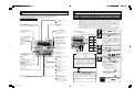
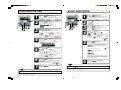
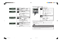
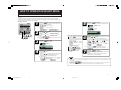
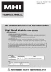
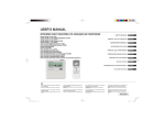
NAMES AND FUNCTIONS OF THE REMOTE CONTROLLER SWITCHES
The figure below shows the remote controller with the cover opened. Note that all the items that may be displayed in the liquid crystal display area are shown in the figure for the sake of explanation.
Characters displayed with dots in the liquid crystal display area are abbreviated.
Pull the cover downward to open it.
Ventilation display
Displays during ventilation operation.
See page 14.
Central control display
Weekly timer display
Displayed when the air conditioning
system is controlled by the option controller.
Displays the settings of
the weekly timer.
Timer operation display
Operation setting display area
Displays the settings related to
timer operation.
Displays setting temperature,
airflow volume, operation mode and
operation message.
Temperature setting switches
Operation/Check indicator light
These switches are used to set
the temperature of the room.
During operation: Lit in green
In case of error: Flashing in red
TIMER switch
Operation/Stop switch
This switch is used to select
a timer mode.
See page 4.
This switch is used to operate and
stop the air conditioning system.
Press the switch once to operate
the system and press it once again to
stop the system.
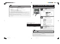
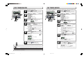
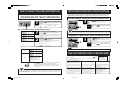
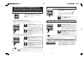
HOW TO USE THE AIR CONDITIONING SYSTEM
HOW TO OPERATE THE AIR CONDITIONING SYSTEM
Request: ● When you operate the air conditioning system at the start of the season or after it has been stopped for a prolonged
period, turn the power switch on (ON) 12 hours before starting the air conditioning operation in order to protect the
air conditioning system (the current is conducted into the crank case and warms the compressor). Do not turn the power
supply switch off during the season. (The current is conducted to the crank case heater while the compressor is stopped,
keeping the compressor warm and preventing failure of the compressor due to accumulation of liquid refrigerant.)
● Do not turn the power supply switch off during the season. Do not turn the power supply switch of an
unused indoor unit off either, keep it “ON.” If the power supply to one of the indoor units in the same
system is turned off, water may leak from the indoor unit (drained water overflows).
● Turn the power supply switch off during the off-season in order to save electricity. (If the power supply switch is kept turned on, current
continues to be conducted to the crank case heater and power is consumed even if the air conditioning system is not operated.)
Setting temperature
Fan speed mode
Operation mode
DRY
1 COOL
3 FAN
HEAT
AUTO
MODE switch
This switch is used to switch between
operation modes.
FAN SPEED switch
Timer setting switches
This switch is used to set the
airflow volume.
These switches are used to set
the timer mode and time.
See page 4 and 13.
VENT switch
This switch operates connected ventilators.
See page 14.
GRILL switch
This switch has no function.
When this switch is pressed,
(Invalid Operation)
is displayed, but it does not mean a failure.
AIR CON No. (Air conditioning system No.) switch
Displays the number of the connected
air conditioning system.
LOUVER switch
This switch is used to operate/stop
the swing louver.
See page 14.
Operation mode
5 42
Guideline for room temperature setting
Cool ............................... 26 to 28°C
Dry ................................. 21 to 24°C
Heat ............................... 22 to 24°C
Fan ................................ Not necessary to set the room temperature
● The settings of operation mode, temperature and airflow volume adjustment can be changed even when
the air conditioning system is stopped. When a switch
is pressed while the operation is stopped, the corresponding display is turned on and you can change the
setting. The display turns on for three seconds after
changing the setting, then turns off automatically.
SET switch
This switch is used to apply the timer
operation setting.
See page 4 to 16.
This switch is also used to make silent
mode operation settings.
See page 13.
CHECK switch
This switch is used at servicing.
TEST switch
RESET switch
This switch is used during test operation.
Press this switch while making settings
to go back to the previous operation.
See page 4 to 15.
This switch is also used to reset the
“FILTER CLEANING” message display.
(Press this switch after cleaning the air filter.)
● The display of “
” flashes
and the operation is switched to “Fan” in the following case
because the operation modes do not match.
(1) When other indoor units are operating in different modes
(with KXR, the heating/cooling free layout multi system, it
is possible to operate indoor units in different cooling/heating modes).
● Do not turn the air conditioning system on/off frequently.
● Do not use sharp objects to press the remote controller
switches.
1
2
3
4
5
Press the “
” switch.
The air conditioning system starts operating.
Press the “
MODE” switch.
The range of operation modes is displayed according to the
model of the indoor unit.
Every time the switch is pressed, the display changes in the
(COOL)” → “
(FAN)” → “
order of “ (DRY)” → “
(HEAT)” and then “
(AUTO)”. (The automatic operation
can only be selected in case of the heating/cooling free
layout multi system KXR. The automatic operation cannot be
selected in case of KX.)
Press the Temperature setting switches.
Press the
or
Press the “
switch to set the room temperature.
FAN SPEED” switch.
The range of fan speed modes is displayed according to
the model of the indoor unit.
In case of 3-speed:
In case of 2-speed:
In case of 1-speed: The switch operation is disabled.
Press the “
LOUVER” switch.
If the indoor unit is equipped with the auto swing
function, the message “
” is
LOUVER ”
displayed when you press the “
switch, and the swing louver moves up and down.
If the indoor unit is not equipped with the auto swing function,
the message “
” is displayed.
● Stopping the louver.
1. Press the switch once while the louver is moving to
display the stop positions in order.
2. Press the switch once again at the desired stop
position to stop the louver at that position.
Page 14
Effective stop position.
At automatic operation: Middle
At cooling/dehumidifying operation: Horizontal
At heating operation: Downward
Page 14
Stop
Press the “
” switch.
3
PCA012A001J_E_P03
3
06.9.13, 14:31
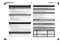
NOTE
● If you press any of the switches above and “
HOW TO PERFORM THE TIMER OPERATION
” is displayed, the switch has no function.
● When you operate the air conditioning system for the first time after turning the power supply on, the air conditioning system
starts operating with the following settings. Change the settings according to your preference.
Central control ........................................ Turned off
Operation mode ...................................... If automatic mode is available: AUTO COOL
If automatic mode is not available: COOL
Setting temperature ................................ 23 °C
Fan speed ...............................................
Louver position ....................................... Horizontal
When automatic operation is disabled, the air conditioning system operates in the following mode:
COOL if the remote controller suction temperature is 17 °C or more
HEAT if the remote controller suction temperature is less than 17 °C
● The operation may be stopped if you increase/decrease the setting temperature by pressing the temperature setting switches.
This occurs because the temperature controller is activated; this is not a failure.
● At cooling (heating), the air conditioning system may activate the cooling (heating) operation to maintain a comfortable room
temperature even when the room temperature is at the setting temperature or less (more); this is not a failure.
● During dehumidifying operation, the fan speed is adjusted automatically according to the room temperature, and may therefore
change repeatedly between the strong, weak and stop speeds. The airflow volume cannot be adjusted by the FAN SPEED
switch.
● If the heating/cooling free layout multi system KXR is used and the operation mode is changed (from COOL to HEAT or from
HEAT to COOL), the airflow volume becomes weak for three minutes.
● During automatic operation, the mode is switched between COOL and HEAT automatically according to the difference between
the setting temperature and room temperature to keep the room temperature constant (in case of the heating/cooling free layout
multi system KXR).
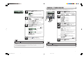
SELECTING TIMER MODES
1
Press the “
TIMER” switch.
The remote controller goes into the timer mode.
The “current day of the week” and “current time” are displayed and the subsequent steps are automatically displayed
as follows.
[Example] In the case of Monday, 10 o'clock in the morning
‚
Display area: “
”
“
“
”
” (lit for 1 second)
‚
1
3
” (lit for 1 second)
“
‚
2
” (lit)
“
2
Press the
or
switch.
If you press the
switch, the display of the following timer
modes is switched in the downward direction.
” (Adjust the current time)
“
‚
” (Turn off after the specified time)
“
‚
” (Turn off at the specified time)
“
‚
“
” (Turn on at the specified time)
‚
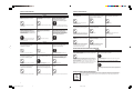
Combination of Modes that can be Set Together
( : Possible, × : Not possible)
” (Select the weekly timer mode)
“
Sleep timer
Off timer
On timer
Weekly timer
×
Sleep timer
×
×
Off timer
×
On timer
×
×
×
×
Weekly timer
If you select a combination of modes that cannot be set together and press
” (Invalid Operation)
the SET switch, the message “
is displayed for 3 seconds, and the display returns to the display selected
in step 2.
‚
“
” (Cancel the timer setting)
If you press the
switch, the display of the timer modes is
switched in the upward direction.
3
Press the “
SET” switch.
The selected timer mode is committed.
For instructions on using each timer mode setting, see the
next page and beyond.
It is also possible to select a combination of timer modes. The
upper left modes can be selected at the same time.
NOTE
● If you press the “
” switch while in the timer setting mode, the remote controller exits from the timer mode
and returns to the original display. Please be aware that settings that have not been committed become invalid.
● If you have selected the on timer mode and either the off timer or sleep timer mode at the same time with the same time setting,
the timer mode that turns off the operation (the off timer or sleep timer mode) takes the precedence.
” is displayed, the switch cannot be operated because the
● If you press any of the timer-related switches and “
switch operation is disabled. To enable the operation, consult the dealer from whom you purchased the air conditioning system.
● If you do not press any switches for 60 seconds after entering the timer mode, the remote controller automatically exits from the
timer mode and returns to the original display.
● If a power failure occurs, the timer settings that have been specified are canceled. Weekly timer settings will return to the display
where all days of the week are selected as “holidays” after the power failure.
4
PCA012A001H_E_P04
4
05.11.16, 12:15
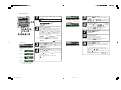
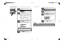
ADJUSTING THE TIME
SLEEP TIMER MODE
In this mode, the air conditioning system stops operating when the set time has elapsed.
Timer operation is performed based on the time adjusted with the steps described in this section.
Make sure to adjust the remote controller to the current time correctly.
7
1
2,4,6
3,5
1
2
Press the “
TIMER” switch.
The remote controller goes into the timer mode.
The “current day of the week” and “current time” are displayed and the
subsequent procedures are automatically displayed in the following order.
“
”‡“
”‡“
”
Press the “
The remote controller goes into the adjusting the time mode.
The display area shows the following:
“
”(
“
” (Current time)
flashes)
1
”
“
3
6
SET” switch.
Press the
or
switch.
Set the
mark displayed above the days of the week to
indicate the current day of the week.
Press
to move to the right and
“
alternately.
” and “
3,5
2,4
to move to the left.
” are displayed
Note: If you press the “
RESET” switch, the remote comtroller
will return to one screen earlier and display “
”.
4
5
Press the “
or
6
7
NOTE
5
switch.
“
” and “
” are displayed
alternately.
Adjust the displayed time to the current time.
● Press the
or
switch briefly to increase or decrease
the displayed value by 1 minute.
or
switch, the display
● If you continue pressing the
will change in increments of 10 minuutes.
RESET” switch, the remote
Note: If you press the “
controller will return to one screen earlier.
Press the “
Press the “
finished.
” switch once time setting is
Press the
switch one time.
“
”
‚
” (first press)
“
Press the “
SET” switch.
The remote controller goes into the sleep timer mode.
” flashes and
[Example] “
” turns on.
“
Press the
or
switch.
The display changes in the order of “
”,
“
” etc., to “
” and then
“
”. Select the desired number of hours.
” and “
” are displayed
“
alternately.
Press the “
SET” switch.
The sleep timer has been set.
The air conditioning system starts operating if the sleep timer
is set while the air conditioning system is stopped.
“
” is displayed in the display area. The
display then returns to the timer mode selection screen as
shown below.
Step 2
<If set to turn off after 10 hours>
“
” (lit)
” (lit for 2 seconds)
“
‚
“
“
” (lit)
” (lit)
After the setting, the remaining time is displayed in decrements of 1 hour as the time passes. The air conditioning
system stops operating when the set time has elapsed. The
time display also turns off.
NOTE
SET” switch.
The time display changes from flashing to lit.
“
” is displayed and the current time is set.
After 2 seconds, the remote controller returns to the timer
”.
mode selection screen and displays “
Step 1
TIMER” switch.
The remote controller goes into the timer mode.
The “current day of the week” and “current time” are displayed and the
subsequent procedures are automatically displayed in the following order.
“
”‡“
”‡“
”
RESET” switch, the remote controller
Note: If you press the “
”.
will return to on screen earlier and display “
Step 2
SET” switch.
The day of the week is committed and the
mark changes
from flashing to lit.
The “current time” flashes in the on timer display area and
“
” is displayed in the display area.
Press the
1
2
3
4
Press the “
6
Press the “
” switch once.
This completely ends the time setting procedure.
NOTE
● If you press the “
” switch while in the timer setting mode, the remote controller exits from the timer mode
and returns to the original display.
● If you do not press any switches for 60 seconds after entering the timer mode, the remote controller automatically exits from the
timer mode and returns to the original display.
● If you press the “
” switch while in the timer setting mode, the remote controller exits from the timer mode
and returns to the original display. Please be aware that settings that have not been committed become invalid.
● If you do not press any switches for 60 seconds after entering the timer mode, the remote controller automatically exits from the
timer mode and returns to the original display.
PCA012A001J_E_P05
5
5
06.9.6, 10:39
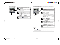
OFF TIMER MODE
ON TIMER MODE
In this mode, the air conditioning system stops the operation at the set time.
6
1
2
Press the “
In this mode, the air conditioning system starts the operation at the set time. The temperature at the
start of operation can also be set.
TIMER” switch.
The remote controller goes into the timer mode.
The “current day of the week” and “current time” are displayed and the
subsequent procedures are automatically displayed in the following order.
“
”‡“
”‡“
”
Press the
10
8
switch two times.
“
”
‚
” (first press)
“
1
2
Press the “
TIMER” switch.
The remote controller goes into the timer mode.
The “current day of the week” and “current time” are displayed and the
subsequent procedures are automatically displayed in the following order.
“
”‡“
”‡“
”
Press the
switch three times.
“
”
‚
” (first press)
“
‚
‚
” (second press)
“
” (second press)
“
‚
1
3,5
2,4
3
4
Press the “
SET” switch.
The remote controller goes into the OFF timer mode.
[Example] “
” flashes and
“
Press the
” turns on.
or
1
3,5,7,9
2,4,6
switch.
“
” and “
” are displayed alternately.
Set the time at which you want to stop the operation.
● Setting “hours”
Keep the
or
switch pressed long enough to change the “hour” display in
increments/decrements of 1 hour. Release the switch to stop changing the hours.
● Setting “minutes”
Press the
or
switch briefly to increase or decrease
the displayed value by 10 minutes.
3
4
RESET” switch, the remote
Note: If you press the “
controller will return to one screen earlier and display
”.
Step 2
“
5
Press the “
5
” (lit)
“
” (lit for 2 seconds)
‚
“
6
Press the
” flashes and
” turns on.
or
switch.
“
” and “
” are displayed
alternately.
Set the time at which you want to start the operation.
● Setting “hours”
Keep the
or
switch pressed long enough to change
the “hour” display in increments/decrements of 1 hour.
Release the switch to stop changing the hours.
● Setting “minutes”
Press the
or
switch briefly to increase or decrease
the displayed value by 10 minutes.
Press the “
SET” switch.
The on timer has been set.
The display area shows the display shown to the left.
<If set at 10:00 am>
” (lit)
” (lit)
RESET” switch, the remote
Note: If you press the “
controller will return to one screen earlier.
6
” switch once.
This completely ends the time setting procedure.
Press the
If you press the
If you press the
or
switch.
switch, “
switch, “
” is displayed.
” is displayed.
To set the temperature at the specified time, select
“
”.
To skip temperature setting, select “
NOTE
”.
● Proceed to step 7 to set the temperature.
● Proceed to step 9 if you do not wish to set the temperature.
” switch while in the timer setting mode, the remote controller exits from the timer mode and returns to the original display.
● If you do not press any switches for 60 seconds after entering the timer mode, the remote controller automatically exits from the
timer mode and returns to the original display.
6
PCA012A001H_E_P06
[Example] “
“
“
● If you want to start operating the air conditioning system with the off timer setting, the air conditioning system must be operated before the timer is set.
● If you press the “
SET” switch.
The remote controller goes into the ON timer mode.
“
” (lit)
” (lit)
“
The air conditioning system stops operating at 6 o'clock in the afternoon.
The time display also turns off.
Press the “
Press the “
RESET” switch, the remote
Note: If you press the “
controller will return to one screen earlier and display
”
Step 2
“
SET” switch.
The off timer has been set.
“
” is displayed in the display area. The display
then returns to the timer mode selection screen as shown below.
Step 2
<If set at 6:00 pm>
“
” (third press)
“
6
05.11.16, 12:17
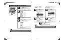
WEEKLY TIMER MODE
■ Selecting Weekly Timer Modes
With this mode, it is possible to perform up to four on timer or off timer operations for each day of the week.
It is also possible to set four timer operations, using either the on timer or off timer only.
7
Press the “
SET” switch.
The display area shows the display shown to the left.
<If set at 10:00 am>
“
” (lit)
” (The display of the currently set temperature
“
flashes.)
“
” (lit)
8
Press one of the temperature setting switches,
or
.
“
” and “
” are displayed
alternately.
or
switch to increase or dePress either the
crease the displayed value by 1°C.
Set the temperature at the start of operation.
9
“
”
” (first press)
“
” (second press)
1
3,5
2,4
‚
‚
” (fourth press)
“
3
4
SET” switch.
” (third press)
“
Press the “
Press the
switch.
The display of the following timer modes is switched in the
downward direction.
” (for setting the timer)
“
” (if the temperature was
SET” switch.
The remote controller goes into the weekly timer mode.
The display area shows “
”.
‚
” (for setting the selected day of the week
to a holiday)
“
” (lit for 2 seconds)
‚
‚
“
“
” (if the temperature was
set) (lit)
“
” (lit)
The air conditioning system starts operating at the set
temperature at the set time.
The time display turns off.
10
switch four times.
‚
“
The on timer is set and the display area shows
“
” and then returns to the timer mode
selection screen as shown below.
Step 2
<If set at 10:00 am>
“
set) (lit)
“
2
Press the
TIMER” switch.
The remote controller goes into the timer mode.
The “current day of the week” and “current time” are displayed and the
subsequent procedures are automatically displayed in the following order.
“
”‡“
”‡“
”
‚
Note: If you press the “
RESET” switch, the remote
controller will return to one screen earlier.
Press the “
1
Press the “
” (for checking the timer settings and
canceling individual settings)
switch, the display of the timer modes is
If you press the
switched in the upward direction.
Select one of the modes.
Note: If you press the “
RESET” switch, the remote
controller will return to one screen earlier and display
”.
“
Press the “
” switch once.
Step 2
This completely ends the time setting procedure.
5
NOTE
● If you press the “
” switch while in the timer setting mode, the remote controller exits from the timer mode
and returns to the original display.
● If you have selected the on timer mode and either the sleep timer or off timer mode, the temperature setting of the on timer is not
displayed.
● If you have selected the same time setting for the on timer mode and either the off timer or sleep timer mode simultaneously, the
timer mode that turns off the operation (the off timer or sleep timer mode) takes the precedence.
● If you do not press any switches for 60 seconds after entering the timer mode, the remote controller automatically exits from the
timer mode and returns to the original display.
Press the “
SET” switch.
The selected mode is committed.
NOTE
● If you press the “
” switch while in the timer setting mode, the remote controller exits from the timer mode
and returns to the original display.
● If you do not press any switches for 60 seconds after entering the timer mode, the remote controller automatically exits from the
timer mode and returns to the original display.
7
PCA012A001H_E_P07
7
05.11.16, 12:18
■ Weekly Timer Setting
1
12
Step 1 to 5 in “Selecting Weekly Timer Modes ” on page 7.
The display area shows the following:
“
”(
flashes)
“
3,5,7,9,
11,13
2,4,6,8,10
2
5
In the weekly timer mode, select and commit
”.
“
Press the
<If “
” was selected>
6
”
or
switch.
3
4
<Example>
Number 1
Press the “
7
8
” mark next to a number
flash and move downward.
Press the
switch to move the mark upward.
1
Number 3
2
3
4
Number 4
Note: Four operations can be set with only
on timers or only off timers.
8
PCA012A001H_E_P08
8
Press the
or
switch.
If you press the
switch, “
” is displayed.
switch, “
” is displayed.
If you press the
Press the switch corresponding to the timer you want to set.
Press the “
SET” switch.
“
Press the
” is displayed.
or
switch.
Set the time.
See step 2 on page 6 for the on timer.
See step 2 on page 6 for the off timer.
Press the “
SET” switch.
The time display changes from flashing to lit and the setting
is committed.
If you have set the off timer operation, the first setting has
been completed.
made the setting (
‡
) and the display shown to the
left appears.
Proceed to “
Next Setting and Exiting Weekly Timer Mode”
on page 9.
If you have set the on timer operation, “
” is
displayed; proceed to step 10.
switch.
switch to make the “
“
” or “
” is displayed. The
settings made so far are committed and the display changes
as shown to the left.
A “_” mark is lit under the day of the week for which you
It is possible to set timer for four times per day; select a timer
number you want to set.
Press the
Number 2
9
SET” switch.
or
SET” switch.
” mark next to the number changes from flashing to lit.
Note: If you press the “
RESET” switch, the remote
controller will return to one screen earlier.
The day of the week is committed and the
mark changes
from flashing to lit.
“
” is displayed and the display area shows
the display shown to the left.
Press the
The “
Note: If you press the “
RESET” switch, the remote
controller will return to one screen earlier.
Set the “
” mark displayed above the days of the week to
indicate the day of the week for which you want to set the
timer.
Press
to move to the right and
to move to the left.
switch, the
marks displayed
If you keep pressing the
above “MON” to “FRI” or “SUN” to “SAT” flash at the same
time. Select this if you want to make the same settings for
“MON” to “FRI” or “SUN” to “SAT.”
“
” and “
” are displayed
alternately.
RESET” switch, the remote
Note: If you press the “
controller will return to one screen earlier and display
”.
“
Step 3 in page 7
<If Monday is set>
Press the “
05.11.16, 12:18
■ Next Setting and Exiting Weekly Timer Mode
”, “
After the display of “
10
11
Press the
or
Press the “
1
switch.
Select either “
” or “
To set the temperature at the specified time, select
“
”.
To skip temperature setting, select “
”.
”, the first setting has
‡
) and the display shown to the
made the setting (
left appears.
Proceed to step 1“Next Setting and Exiting Weekly
Timer Mode,” at right.
”,
If you have selected “
” is displayed; proceed to step 12.
“
” and “
1
2
” are displayed
or
switch to increase or
Press either the
decrease the displayed value by 1 °C.
Set the temperature at the start of operation.
RESET” switch, the remote
Note: If you press the “
controller will return to one screen earlier and display
”.
“
13
Press the “
switch.
switch, the display of the items is
If you press the
switched in the upward direction.
Select either one of them.
2
Press one of the temperature setting switches,
or
.
“
alternately.
or
Select the following items.
switch, the display of the following items
If you press the
is switched in the downward direction.
” (for selecting the next timer operation
“
number for the same day of the week)
‚
” (for selecting the next day of the week)
“
‚
” (for exiting the timer mode)
“
A “_” mark is lit under the day of the week for which you
12
Press the
”.
SET” switch.
If you have selected “
been completed.
” is displayed.
SET” switch.
The first setting has been completed.
The temperature display changes from flashing to lit. A “_”
mark is lit under the day of the week for which you made the
setting (
‡
) and the display shown to the left appears.
Proceed to step 1“Next Setting and Exiting Weekly
Timer Mode,” at right.
Press the “
SET” switch.
If you have selected “
”, “
is displayed.
Repeat step 4 and onward on page 8.
”
If you have selected “
“
” is displayed.
Repeat step 2 and onward on page 8.
”,
If you have selected “
ler exits from the timer mode.
”, the remote control-
■ Display after Setting Weekly Timer Modes
● The day of the week for which settings have been made is underlined.
mark is displayed above the current day of the week.
● The
mark indicates the next setting number to be activated,
● The timer operation numbers set for the current day all turn on, the
and the set time is displayed.
● The set timer operations are executed in the set order, and the number and time display turns off when all the timer operations
for the current day have been executed.
NOTE
● If you press the “
” switch while in the timer setting mode, the remote controller exits from the timer mode
and returns to the original display. Please be aware that settings that have not been committed become invalid.
● If you select a day of the week for which settings have already been made in the selection of the day of the week, all the timer
numbers that have been set are displayed. The timer settings displayed, however, correspond to the number with the “ ” mark
displayed next to it. At this point, if you specify different settings, the displayed settings are changed to the new settings.
● If you set the same time for the on timer and off timer operations for the same day, the off timer is set.
● If you do not press any switches for 60 seconds after entering the timer mode, the remote controller automatically exits from the
timer mode and returns to the original display.
9
PCA012A001J_E_P09
9
06.9.13, 14:41
■ Weekly Timer Holiday Setting
It is possible to temporarily “disable” already set timer settings for individual days of the week. If the holiday setting is
canceled, the settings are enabled again.
1
1
2
3
In the weekly timer mode, select and commit
”.
“
Steps 1 to 5 in “Selecting Weekly Timer Modes“ on page 7
The display area shows the following:
“
”(
flashes)
”
“
4
2
3
■ Canceling Holiday Setting
2
Press the
or
switch.
Set the
mark displayed above the days of the week to
indicate the day of week for which you want to set timer
holiday.
Press
to move to the right and
to move to the left.
switch, the
marks displayed
If you keep pressing the
above “MON” to “FRI” or “SUN” to “SAT” flash at the same
time. Select this if you want to set “MON” to “FRI” or “SUN” to
“SAT” to holidays at the same time.
“
” and “
” are displayed
alternately.
3
“
” (lit)
” (lit for 2 seconds)
“
‚
“
“
4
10
Press the “
SET” switch.
The display of ( ) turns off and the following is displayed.
After the holiday setting has been canceled, the remote
controller returns to step 1. Repeat steps 2 and 3 to continue
canceling further holiday settings.
” (lit)
” (lit for 2 seconds)
Press the “
” (lit)
” (lit)
” switch once.
This completely ends the noliday setting procedure.
● If you press the “
” switch while in the timer setting mode, the remote controller exits from the timer mode
and returns to the original display. Please be aware that settings that have not been committed become invalid.
● If you do not press any switches for 60 seconds after entering the timer mode, the remote controller automatically exits from the
timer mode and returns to the original display.
” (lit)
” (lit)
” switch once.
This completely ends the noliday setting procedure.
10
PCA012A001H_E_P10
switch.
NOTE
● If you selected a day of the week for which no timer operation is set,
“
” is displayed for 2 seconds and the display returns
to the one shown in step 1.
Press the “
or
Set the
mark displayed above the days of the week to
indicate the day of the week for which you want to cancel the
timer holiday setting.
Select a day of the week that has been set as holiday.
‚
NOTE
4
Press the
“
“
SET” switch.
The
mark above the day of the week changes from
flashing to lit, the day set as a holiday is lit with ( ), and the
following is displayed. After the holiday setting has been
completed, the remote controller returns to step 1. Repeat
steps 2 and 3 to continue setting further holidays.
Steps 1 to 5 in “Selecting Weekly Timer Modes“ on page 7
“
“
RESET” switch, the remote
Note: If you press the “
controller will return to one screen earlier and display
”.
“
Step 4 in page 7
Press the “
In the weekly timer mode, select and commit
”.
“
05.11.16, 12:19
■ Checking Weekly Timer Modes
■ Canceling Weekly Timer Mode Settings
It is possible to cancel weekly timer mode settings of each day of the week, as well as individual setting numbers.
See “Timer Operation Cancellation Mode” on page 12 to cancel settings of all the days of the week at once.
1
In the weekly timer mode, select and commit
”.
“
1
Steps 1 to 5 in “Selecting Weekly Timer Modes“ on page 7
The remote controller shows the display shown to the left and
the settings for the number of the earliest timer operation for
the set day of the week.
3
2
2
3
Press the
or
Press the “
3,4
Steps 1 to 5 in “Selecting Weekly Timer Modes“ on page 7
The remote controller shows the display shown to the left and
the settings for the number of the earliest timer operation for
the set day of the week.
5
switch.
The settings are displayed for each day of the week, in the
order of their setting numbers.
Press the
switch to display settings starting from Sunday,
in order from the smallest setting number.
Press the
switch to display the settings in the reverse
order.
“
” and “
” are displayed
alternately.
In the weekly timer mode, select and commit
”.
“
2
2
” switch once.
Press the
or
switch.
The settings are displayed for each day of the week, in the
order of their setting numbers.
Press the
switch to display settings starting from Sunday,
in order from the smallest setting number.
Press the
switch to display the settings in the reverse
order.
Select the day of the week and setting number corresponding
to the weekly timer setting you want to cancel.
“
” and “
” are displayed
alternately.
The remote controller exits from the timer mode.
3
Press the “
SET” switch.
“
” is displayed.
4
Press the “
5
RESET” switch, the remote
Note: If you press the “
controller will return to one screen earlier and display
”.
“
SET” switch.
“
” is displayed. The displayed setting
disappears and is canceled.
‚
” is displayed again.
“
Repeat steps 2 to 4 to continue canceling other settings.
Press the “
” switch once.
The remote controller exits from the timer mode.
NOTE
● If you press the “
” switch while in the timer setting mode, the remote controller exits from the timer mode
and returns to the original display.
● If you do not press any switches for 60 seconds after entering the timer mode, the remote controller automatically exits from the
timer mode and returns to the original display.
11
PCA012A001J_E_P11
11
06.9.6, 10:40
TIMER CANCELLATION MODE
1
7
2
1
Press the “
The remote controller goes into the timer mode.
The “current day of the week” and “current time” are displayed and the subsequent procedures are automatically
displayed in the following order.
“
”‡“
”‡“
Press the
If “
“
TIMER” switch.
switch five times.
“
”
”, “
” was selected
5
”
‚
” (first press)
“
‚
3,5,6
2,4
” (second press)
“
Press the “
5
” (third press)
“
Press the “
SET” switch.
The following is displayed.
(However, if no setting has been made,
there will be no change from the
display in step 4 even if the set switch
is pressed.)
If you stop canceling, press the
‚
If you stop canceling, press the
” (fifth press)
“
3
4
Press the “
SET” switch.
The remote controller goes into the timer operation cancellation mode.
Press the
or
“
“
6
switch.
Select the timer mode you want to cancel.
If you press the
switch, the display of the following timer
modes is switched in the downward direction.
RESET” switch to return to the
” display (step 4).
RESET” switch to return to the
” display (step 4).
Press the “
SET” switch.
The timer display area turns off, the
message “
” is
displayed for 2 seconds, and
“
” is displayed again
(step 4).
Repeat steps 4 to 6 to continue
canceling other timer mode settings.
6
Press the “
SET” switch.
The day display area turns off,
“
” is displayed for
two 2 seconds, and
“
” is displayed again
(step 4).
With this operation, settings for all the
days of the week are canceled.
”
“
7
·
‚
“
”
·
‚
Press the “
” switch once.
This completely ends the timer cancel
procedure.
NOTE
”
“
·
‚
“
“
“
” (fourth press)
‚
● If you press the “
” (for canceling all days of the week)
switch, the display of the timer modes is
If you press the
switched in the upward direction.
” switch while in the timer setting mode, the remote controller exits from the timer mode
and returns to the original display. Please be aware that settings that have not been committed become invalid.
● If you do not press any switches for 60 seconds after entering the timer mode, the remote controller automatically exits from the
timer mode and returns to the original display.
NOTE
● If you press the “
” switch while in the timer setting mode, the remote controller exits from the timer mode
and returns to the original display.
● If you do not press any switches for 60 seconds after entering the timer mode, the remote controller automatically exits from the
timer mode and returns to the original display.
12
12
SET” switch.
The settings of the selected timer mode
are displayed as shown below.
(However, if no setting has been made,
there will be no change from the
display in step 4 even if the set switch
is pressed.)
<Display example where
“
” was selected>
” was selected.
If “
Perform the following operation to cancel settings for
all the days of the week.
See “Canceling Weekly Timer Mode Settings“ on page
11 to cancel settings for each day of the week.
‚
“
PCA012A001H_E_P12
” or
05.11.16, 12:20
HOW TO OPERATE IN SILENT MODE
SILENT MODE
When the silent mode is set, the air conditioning system operates more quietly, i.e., noise from the outdoor unit is
reduced.
The system starts the silent operation at the set time and stops the silent operation after the set time has passed.
When the air conditioning system is set to operate in the silent mode, it repeats the silent operation and stopping every
day at the same time, until the silent mode is canceled.
■ Setting Silent Mode
1
Press the “
5
SET” switch for 3 seconds or more.
The air conditioning system enters the silent mode and the
display area shows the following.
“
” (lit for 1 second)
‚
“
” (lit for 1 second)
2
1,3,5,7
2,4,6
Press the
” or “
or
If you press the
displayed.
If you press the
played.
Select “
” is
switch, “
” is dis-
SET” switch.
The following setting display appears.
“
“
” (flashing)
” (lit)
■ Canceling Silent Mode (Settings)
1 Press the “
SET” switch for 3
seconds or more.
The air conditioning system enters
the silent mode and the display area
shows the following.
“
”(lit for 1 second)
‚
“
”(lit for 1 second)
‚
”(lit)
“
2 Press the
Select “
4
Press the
or
” (flashing)
” (lit)
switch.
switch, “
RESET” switch, the remote controller
Note: If you press the “
returns to the original display.
3
” (flashing)
” (lit for 2 seconds)
“
“
“
“
” (lit)
”.
Press the “
SET” switch.
The on time is committed and the following display appears.
‚
‚
“
Press the “
switch.
Set the on time.
● Setting “hours”
or
switch pressed long enough to change
Keep the
the “hour” display in increments/decrements of 1 hour.
Release the switch to stop changing the hours.
● Setting “minutes”
Press the
or
switch briefly to increase or decrease
the displayed value by 10 minutes.
“
” and “
” are displayed alternately.
or
switch
”
SET” switch
3 Press the “
” is displayed.
“
The Silent Mode settings are
canceled.
6
Press the
or
switch.
Select an off time.
If you press the
switch, the set number of hours increases in increments of 2 hours, and the display changes in
the order of “
”, “
”, etc., to “
” and then
“
”.
switch, the set number of hours deIf you press the
creases in decrements of 2 hours.
“
” and “
” are displayed
alternately.
RESET” switch, the remote
Note: If you press the “
controller will return to one screen earlier and display
”.
“
7
Press the “
SET” switch.
The settings are committed and displayed.
“SET COMPLETE” is displayed and the silent mode setting is
finished.
The display of the settings is turned off and the remote
controller returns to the original display.
NOTE
● After the silent mode is set, the following is displayed for 3 seconds at the set time and the remote controller returns to the
original display.
”
At the on time: “
”
At the off time: “
” switch while in the Silent setting mode, the remote controller exits from the Silent setting mode and
● If you press the “
returns to the original display. Please be aware that settings that have not been committed become invalid.
13
PCA012A001H_E_P13
13
05.11.16, 12:21
HOW TO ADJUST THE AIRFLOW DIRECTION
AIRFLOW ADJUSTMENT BY THE LOUVER SWITCH
(FOR INDOOR UNITS WITH THE AUTO SWING FUNCTION)
■ To Move the Swing Louver
1
VENTILATION MODE OPERATION (WHEN A VENTILATOR IS INSTALLED)
When the ventilator is set to "NO VENTI LINK" (Ventilation not linked), the ventilator can be set to ON/OFF
by itself, without regard to the operation or stopping of the air conditioner. When the ventilator is set to
"VENTI LINK SET" (Ventilation linked), the ventilator will operate when the air conditioner operates.
NON-LINKED VENTILATION OPERATION
1
Press the “
LOUVER” switch while the air conditioning system is operating and the swing louver is
stopped.
The swing louver moves up and down continuously and
” is displayed for 3 seconds.
“
■ To Fix the Position of the Swing Louver
1
2
To Fix the Position of the Swing Louver
Press the “
LOUVER” switch once while the swing
louver is moving.
The four available directions in which the swing louver can be
positioned are displayed for 2 seconds each in the order
shown left.
“
VENTI” switch.
” is displayed, and ventilation operation begins.
Press the “
Stop
1
1
Press the “
VENTI” switch a second
time.
NOTE
● If no ventilator is connected, nothing will happen when the ventilation switch is pressed. ("Operation invalid" is displayed.)
LINKED VENTILATION OPERATION
Press the “
LOUVER” switch at the position
you want to stop/fix the louver.
The display stops and the following is displayed, then the
swing louver is stopped and fixed.
1
1
Press the “
Stop
(If fixed at position 1)
” switch.
If a ventilator is connected, ventilation will operate automati” is displayed.
cally. “
Press the “
” switch a scond time.
● Recommended Louver Fix Positions
NOTE
Operation is invalid even if the ventilation switch is pressed.
Cool/Dry
USING THE AIR CONDITIONING SYSTEM IN A COMFORTABLE MANNER
Clean the filer frequently.
Page18
Heat
If you want to fix the louver at this
position, make sure to turn the
vertical louver to the left or right (in
the case of FDE).
Horizontal position
When “
” (PREPARATION OF HEATING ) is displayed,
the swing louver is automatically set at the horizontal position.
When heater preparation is completed and the air conditioning system is
switched to normal operation, the position of the swing louver returns to
the set position.
REQUEST
● The swing louver may be broken if you attempt to move it forcefully with your hands. Do not attempt to move it with your hands.
● Do not direct the airflow downward for extended periods of time at cooling operation. Dew may form on the side panel and drop
from it (in the case of FDE).
If the filter is clogged...
● The cooling/heating efficiency becomes lower. Moreover, electricity is wasted and the operation makes more noise.
● A clogged filter may cause failures.
● Dew may form and drop during the cooling operation.
Do not block the inlet and outlet
openings of the indoor and outdoor
units
Set a moderate room temperature
Block direct sunlight and prevent draft
Excessive force must not be applied to the air
conditioning system; doing so may lead to failure.
Too much cooling or heating is not good for your
health. It is also a waste of electricity.
Block direct sunlight with window blinds and curtains
at cooling. Close the windows and doors except when
ventilation is necessary.
Adjust the airflow direction properly
If your feet feel cold at heating
Do not subject your skin to the airflow from the
air conditioning system for prolonged periods
of time. Protect small animals and plants from
such direct airflow as well.
If the ceiling is high and the warm airflow does
not circulate down to your floor area sufficiently, it is recommended to use a circulation
fan. Consult the dealer for the details.
Stop the operation and turn the
power supply off if there are any
possibilities of lightning strikes
during a thunderstorm
14
PCA012A001H_E_P14
14
The filter should be cleaned
whenever the “FILTER
CLEANING” message is
displayed, as well as at the end
of cooling and heating seasons.
05.11.16, 12:22
Failure to do so may lead to failure of the air
conditioning system.
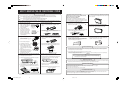
HOW TO MAINTAIN THE AIR CONDITIONING SYSTEM
Cleaning the Air Filter
Clean the air filter regularly to perform cooling and heating operations in the most efficient and economical manner.
Caution: Make sure to stop the operation and turn the power supply switch off when you clean the air filter.
The fan inside rotates at high speeds, leading to injury.
Caution: Fix the steps securely if you use them to install or remove the air filter.
The air conditioning system may fall down or overturn, leading to injury.
How to Remove the Air Filter (other than types whose panels automatically move up/down to make filter cleaning easier)
Remove the air filter according to the procedure for each type.
Ceiling Recessed Type (FDT)
1. Hold the notches (in two
places on the left and right
sides) of the inlet grill and
pull the inlet grill downward, opening it.
PULL
2. Pinch the hook parts (in
two places on the left and
right sides) at the bottom of
the filter as shown in the
figure below and pull the
filter forward while pushing
it upward slightly.
Filter
Ceiling Suspended Type (FDE)
1. Slide the lever of the inlet grill in the direction of the
arrow (➛) and open the grill by swinging it downward.
2. While light pushing up, remove the filter from the tabs
at the left and right, and pull towards the front.
)
Floor Standing, Lowboy Type (Concealed Type)
(FDFU)
Pull the air filter out from the bottom of the unit.
2. While light pushing up, remove the filter from the tabs
at the left and right, and pull towards the front.
Air filter
Tab
Suction grille
Suction grille
Tab
Ceiling Recessed Type, 1-Way Air Direction (FDTS)
1. Slide the lever of the inlet grill in the direction of the
arrow (➛) direction and open the grill by swinging it
downward.
Ceiling Recessed Type (FDTC)
1. Slide the inlet grill levers in the
direction of the arrow ( ), and
open it downwards.
FDTQ Series
1. Slide the lever of the suction grille in the arrow (
direction to open the grille.
Floor Standing, Lowboy Type (Exposed Type) (FDFL)
Remove the front panel and pull the air filter out from the
bottom of the unit.
Air filter
Tab
Hooks
High Static Pressure Duct Type (FDU)
Middle Static Pressure Duct Type (FDUM) (FDQM)
Ceiling mounted duct type (FDUR)
Ultra thin ducted Type (FDQS)
The air filter is mounted at the installation of the air
conditioning system. Please obtain explanations on how
to remove and clean the filter from the dealer from whom
you purchased the air conditioning system.
Tab
Wall mount type (FDK)
1. Pull up the suction grill forward.
Hold the concave sections at both the right and left
side with your hands and pull the suction grill forward.
It stops while being open at about 60°.
2. Lightly hold the handle of the air filter, slightly lift it
upward, and then pull it out forward.
2. Turn the inlet grill stopper.
3. Pull the filter toward you.
Hooks
Hooks
4. When the filter is put in place,
insert the filter into the hooks
on the inlet grill, and be sure to
return the stopper to its original
position.
5. When putting the inlet grill back in
place, slide the levers in the opposite
direction and check to be sure that
the grill does not come open.
2. Push the air filter backward to disengage the front
hook area, then slide the filter forward and remove
it.
How to Clean the Filter
Stopper
1. Clean the filter under running water. If the filter is not very dirty, you can clean it by lightly dusting it off or by using cleaner.
If it is very dirty, dissolve some neutral detergent in lukewarm water (approximately 30 °C), rinse the filter with it, and wash
the detergent away from the filter completely.
Air filter
Front side
Push backward.
Insulation
Remove by sliding forward.
Ceiling Recessed Type, 2-Way Air Direction (FDTW)
1. Push one side of the inlet panel (pin A side) upward.
2. Disengage the panel from pin A
3. Disengage the panel from the pin B and remove the panel.
3 Disengage the pin B side.
Ceiling Recessed Cassetteria Type (FDR)
1. Push the inlet panel upward.
2. Pull the inlet panel outward. When the inlet panel is
disengaged from the pins, it can be opened by
swinging it downward.
2. Dry the air filter and mount it in the unit, then press the filter reset switch.
In the case of unit types whose panels automatically move up/down to make filter cleaning easier, the filter is automatically
set in place by operating the GRILL switch.
CAUTION
● Do not dry the filter under direct sunlight or using fire. The filter will be damaged.
● Do not operate the air conditioning system while the air filter is removed. The air
conditioning system may be damaged.
Maintenance of the Unit
Outer panel frame
Pin B
1 Push the pin A side upward.
2 Disengage the pin A side.
pin
● Clean the unit by wiping it with a piece of soft and dry cloth. If the unit is very dirty, wipe it with a piece of cloth wet with neutral
detergent dissolved in lukewarm water and wipe it off with a piece of cloth soaked in clean water.
Pin A
Inner panel frame
Panel
4. Press the knobs of the air filter inward, remove the
hook area from the air conditioner unit, and remove
the air filter.
Hook
3. Rotate the hooks and disengage the corrugated
filter from the hooks.
4. Slide the flat filter toward the center and remove it.
Flat filter Corrugated filter
At the End of the Season
● Make sure to turn the power supply switch off.
The air conditioning system consumes several tens of watts of electricity even when it is stopped.
● Clean the air filter and mount it.
● Clean the indoor and outdoor units to remove any dirt.
Air filter
Air conditioner unit
Knobs
At the Start of the Season
Hook
Knobs
● Make sure that there is no object blocking the airflow around the inlet and outlet openings of the indoor and outdoor units.
● Inspect the air filter. If it is dirty, clean and mount it.
● Turn the power supply switch on 12 hours before starting the operation.
15
PCA012A001L_E_P15
15
07.3.13, 11:13
TROUBLESHOOTING
Check the following items before requesting service.
The unit does not work at all
Is the power supply switch turned off?
Is there a power failure or is the fuse
blown?
Is the leakage breaker activated?
This situation is dangerous. Turn the
power supply off immediately and contact
the dealer from whom you purchased the
air conditioning system.
ON
OFF
Poor cooling or heating
Is the air filter clogged?
Is the swing louver horizontal (at heating)?
Are there any obstacles blocking the
air inlet and outlet openings?
If the swing louver is
horizontal, the airflow
may not reach down
to the floor.
No air comes out during dehumidifying
operation. The airflow volume cannot be
changed.
During dehumidifying operation, the fan automatically operates in a
weak airflow/stop cycle in order to prevent too much cooling and
temperature increase.
The swing louver moves on its own.
The swing louver automatically swings twice when the power supply
switch is turned on. This is not an error. The swing louver also moves
automatically to the horizontal position when “
”
(PREPARATION OF HEATING) is displayed.
The outdoor unit discharges water or
steam during heating operation.
Water or steam is discharged when frost that has built up on the surface
of the heat exchanger in the outdoor unit is removed (defrost operation).
The operation mode display on the
remote controller flashes (in the case of
cooling, dehumidifying and heating).
The mode display flashes when the operation modes of indoor units are
different and fan operation is performed. Use the indoor units in the
same operation mode or stop the operation of other units (with KXR, the
heating/cooling free layout multi system, it is possible to operate indoor
units in different cooling/heating modes).
The fan of the outdoor unit does not rotate
at operation.
The fan is automatically stopped during defrost operation and heating
operation when the outside air temperature is high. In cooling operation as
well, a function to control the number of fans to be operated is automatically
activated when the outside air temperature becomes low.
Request: The fan, even if it is stopped, may suddenly begin to operate; do
not insert fingers and/or other elongated devices.
Slapping sounds are heard.
These sounds are generated when resin components expand and
contract due to warm air.
Hissing sounds are heard when the
operation is stopped or during defrost
operation.
These sounds are generated when the refrigerant valve inside the air
conditioning system is activated.
The operation started automatically, as
soon as the power supply switch was
turned on.
When the power failure compensation is enabled, the system starts
operating after the power recovers under the same conditions as before
the power failure occurred or the power supply switch was turned off.
Poor cooling
Is direct sunlight coming into the room?
No airflow at heating
Is the unit preparing the heater?
Page 18
Are there any unexpected heat sources in the room?
Are there too many people in the room?
If, after checking the items above, the air conditioning system still does not operate normally, stop operating the air conditioning system and contact the dealer from whom you
purchased the system.
● If the fuse and breaker blow frequently.
● If water drips at cooling/dehumidifying operation.
● If the operation or operation noise is abnormal.
● If the check indicator light flashes.
The following does not mean malfunctions of the unit.
The air conditioning system sounds as if
water is draining from it.
Sounds of rustling or gurgling may be heard when the operation is started, when
the compressor is activated/deactivated during operation, or when the operation
is stopped. These are the sounds of the refrigerant flowing through the system.
Sounds of rustling or gurgling may be
heard from a stopped indoor unit.
These sounds can be heard when the air conditioning system is performing automatic control.
The airflow from the indoor unit smells
bad.
The airflow from the indoor unit may smell bad if the smell of cigarettes,
cosmetics and/or furniture has saturated the air conditioning system.
White vapor is generated from the
indoor unit during operation.
White vapor may be generated during operation if the system is used in
environment where oils and fats are frequently used, such as in restaurants. In this case, consult the dealer and clean the heat exchanger.
The operation switched to fan operation
during cooling operation.
The operation may switch to fan operation automatically to prevent frost
from building up on the surface of the heat exchanger. The operation will
soon return to cooling operation.
The indoor fan does not stop even when
the operation is stopped while heating
operation.
The indoor fan may continue operating for approximately 40 seconds
after the heating unit stops operating in order to remove after-heat of the
auxiliary heater.
Page 18
The setting temperature cannot be
changed (the setting temperature
display flashes).
If the temperature setting is fixed, the setting temperature cannot be
changed even if you press the
and
switches.
The airflow becomes weak if the
operation mode is changed during
operation (in the case of the heating/
cooling free layout multi system KXR).
When you switch the operation mode from Cool to Heat or from Heat to
Cool during operation, the airflow becomes weak for 3 minutes.
WARNING
Turn the power supply off after the fan stops.
The air conditioning system cannot start
operating again immediately after
stopping.
During the first 3 minutes after stopping operation, it is not possible to perform
cooling, dehumidifying or heating operation even if the operation/stop switch is
pressed to indicate “operation.” This is because a circuit for protecting the
compressor is activated (the fan is operating during this period).
16
PCA012A001L_E_P16
16
07.3.13, 11:15
Page 18
ABOUT INSPECTION DISPLAY, FILTER MESSAGE DISPLAY, AIR
CONDITIONING UNIT NUMBER AND OPERATION STANDBY DISPLAY
WHEN THE FILTER CLEANING MESSAGE IS DISPLAYED
The “
” message is displayed if the cumulative
number of operation hours of the indoor unit reaches the set number
of hours in order to notify that the air filter should be cleaned.
■ Clean the air filter.
Page 15
WHEN THE CHECK INDICATOR LIGHT (RED) FLASHES
Error code
The filter cleaning message is displayed in the display area. It is
displayed for 1 second every 5 seconds while the air conditioning
system is operating. It is always lit while the system is stopped.
■ The air conditioning system stops if an error occurs.
At the same time, the check indicator light flashes in red and the error
code is displayed in the on timer display area and the following is
displayed in the display area.
“
”↔“
” (lit for 2 seconds each)
·
(Air conditioning unit No.)
After cleaning
1
1
Air conditioning unit No.
Error Display when Using Multiple Indoor Units
■ If errors have occurred for all the connected air conditioning units
Initially, the error display shows information about the air conditioning unit whose air conditioning unit No. is the
smallest.
Errors of other air conditioning units can be checked with the following procedure.
1
2
2
1
2
2
1
HOW TO DISPLAY AIR CONDITIONING UNIT NO.
1
The remote controller goes into the air conditioning unit No.
display mode.
● If you do not press any switches for 10 seconds after
entering the air conditioning unit No. display mode, the
remote controller automatically exits from the air conditioning unit No. display mode and returns to the original display.
Press the AIR CON No. switch.
The remote controller goes into the air conditioning unit No.
display mode.
● If you do not press any switches for 10 seconds after
entering the air conditioning unit No. display mode, the
remote controller automatically exits from the air conditioning unit No. display mode and returns to the original display.
Press the
Press the “AIR CON No.” switch.
The remote controller goes into the air conditioning unit No.
display mode and shows the smallest air conditioning unit No.
among the connected air conditioning units. All other displays
are turned off.
● If you do not press any switches for 10 seconds after
entering the air conditioning unit No. display mode, the
remote controller automatically exits from the air conditioning unit No. display mode and returns to the original display.
switch.
The air conditioning unit No. and error codes are displayed in
order, starting from the smallest unit number.
Press the
switch to display the air conditioning unit No.
and error codes in the reverse order.
■ If errors have occurred for some of the connected air conditioning units
Only the air conditioning units for which errors have occurred stop operating.
The remote controller shows operating air conditioning units.
1
RESET” switch.
The filter cleaning message disappears.
By operating the AIR CON No. switch, the numbers of the connected air conditioning units and error codes of units with
error history are displayed.
Press the AIR CON No. switch.
Press the
Press the “
2
2
1
Press the
switch.
The air conditioning unit No. is displayed in order starting
from the smallest number, and error codes are displayed for
erroneous air conditioning units.
Press the
switch to display the air conditioning unit No.
and error codes in the reverse order.
NOTE
● The air conditioning unit No. can be displayed while the air conditioning system is being operated, while it is stopped, or while it
is stopped forcefully due to errors.
” and “
” cannot be operated.
● Switches other than “AIR CON No.,” “
ABOUT OPERATION STANDBY DISPLAY
If you press the operation/stop switch when you start operating the air
conditioning system at the start of the season or after it has been
stopped for a prolonged period, “
” is displayed for
several seconds before the display switches to the operation display.
In this case the air conditioning system remains stopped, but this is
not a failure. Please wait for a while, as normal operation will become
possible after a short period of time.
switch.
The air conditioning unit No. is displayed in order starting
from the smallest number, and error codes are displayed for
erroneous air conditioning units.
Press the
switch to display the air conditioning unit No.
and error codes in the reverse order.
NOTE
● If you press the “
If you press the “
” switch once while an error is displayed, the error display turns off and the stop status is displayed.
” switch again, the error display appears.
17
PCA012A001H_E_P17
17
05.11.16, 12:22
ABOUT PREPARATION OF HEATING
CASES WHEN “
“
” (PREPARATION OF HEATING) IS DISPLAYED
ABOUT INSTALLATION, MOVING AND INSPECTION MAINTENANCE
Please observe the following points in order to use the air conditioning system in a safe and comfortable manner.
Make sure to request the dealer to perform any installations, etc.; do not try doing so by yourself.
” is displayed in the remote controller display area in the following cases.
The remote controller displays “
” and the operation display alternately.
● At Starting Heating Operation
In order to prevent cool air from blowing out, the airflow into the room may be stopped depending on the room temperature at the start
of heating operation. Please wait approximately 2 to 7 minutes; the operation automatically switches to the normal heating operation.
● At Defrost Operation (during Heating Operation)
Under conditions where frost may easily build up on the surface of the heat exchanger of the outdoor unit, the heating operation is
automatically stopped for approximately 5 to 10 minutes per hour (both the indoor and outdoor units stop blowing air) and defrost
operation is executed. After the defrost operation is completed, the operation automatically switches back to normal heating operation.
● When the Room Temperature Controller is Activated during Heating
When the room temperature increases and the room temperature controller is activated, the airflow is automatically turned down.
When the room temperature decreases, the operation automatically switches back to normal heating operation.
INSTALLATION LOCATION
Is the system installed in a well ventilated place?
Are there any obstacles? If the airflow is obstructed, the efficiency of the air conditioning system may be lowered and the operation may
become noisy.
Can cool/warm air and operation noise cause problems to your neighbors?
ELECTRICAL WORK
ABOUT HEATING OPERATION
About Heating Operation
● Heat Pump Type Heating
Heat pump type heating refers to a mechanism that heats the room by drawing heat in the air outside the room in by means of the refrigerant.
● Defrost Operation
When heating with a heat pump type air conditioner, frost will eventually build up on the surface of the heat exchanger of the outdoor
unit if the temperature outside the room decreases. If nothing is done, the heating efficiency decreases. In order to deal with this, the
operation is automatically switched to defrost operation to remove the frost. During this period, the airflow of the indoor and outdoor
” is displayed.
units is stopped and “
● Outside Air Temperature and Heating Capacity
The heating capacity of a heat pump type air conditioner decreases as the outside air temperature becomes lower. If the heating
capacity is insufficient, it may be necessary to use other heaters as well.
● Time Required until the Room Temperature Increases
A heat pump type air conditioner circulates warm air in order to warm the entire room; it takes a while for the room temperature to
increase. It is therefore a good idea to start operating early on days with unusually cold mornings, etc.
ABOUT POWER FAILURE COMPENSATION
■
■
●
●
●
Caution: Make sure to perform grounding work.
Do not connect the ground wire to a ground wire connected to any gas pipes, water pipes, lightning conductors or
telephones. If the grounding is incomplete, electric shock may occur.
Caution: It is necessary to install a leakage breaker.
If a leakage breaker is not installed, electric shock may occur.
Electrical work and grounding work must be conducted by qualified personnel according to the standard rules for
electric equipment.
Is the wiring dedicated for the air conditioning system?
Is the remote controller switch mounted correctly?
In the case of exposed wiring, is the wiring fixed with the attached screws?
Is the attached remote controller clamp used for fixing the remote controller cord?
Is the system installed at a height where children cannot reach?
AT MOVING
Warning: Make sure to consult a dealer or specialist if it is required to move and reinstall the air conditioning
system.
If the air conditioning system is installed incorrectly, water leakage, electric shock and/or fire may occur. Note that an
installation fee will be charged for removal and installation.
ABOUT INSPECTION MAINTENANCE
NOTE
● The remote controller has a power failure compensation function, which can be enabled (disabled at shipment from the factory). Please consult the
dealer from whom you purchased the air conditioning system.
■ What is Power Failure Compensation?
● When a power failure occurs or the power supply switch is turned off, this function allows the system to automatically resume operation
with the remote controller settings made before the power failure when the power supply recovers. If the air conditioning system was
stopped before the power failure, it remains stopped after the power recovers.
● Note that the following must be set again with the remote controller.
1 Timer operation settings: All timer operation settings are canceled. Weekly timer settings, however, recover with holiday setting.
2 Auto swing (for remote controllers equipped with this function): The swing louver automatically stops at the horizontal position.
Request: If the power failure compensation is enabled, make sure to stop the operation before turning the power supply switch
off. (If the power supply switch is turned off while the system is operating, the fan of the indoor unit will begin rotating
immediately after the power supply switch is turned on. Moreover, the outdoor unit will start operating approximately
3 minutes after turning the power supply switch on.)
Normally the efficiency of the air conditioning system will become lower after a while, because dirt accumulates inside
the system. This occurs gradually in 3 years or so of usage, depending on the usage conditions and surrounding environment. It is thus necessary to conduct inspection maintenance in addition to regular maintenance. We recommend you
to consult the dealer from whom you purchased the system and sign an inspection contract (charged).
OPERATION RANGE
Request: Please use the system in the following operation range. If the system is operated outside this range,
the protection circuits may be activated to prevent the operation.
Condition
Operation
Room temperature
Approximately 21 to 32°C
If you operate the system for extended
periods of time below approximately
21°C, frost may build up on the surface
of the heat exchanger, and the cooling/
Dehumidifying operation
dehumidifying operation may not be
satisfactory.
Temperature outside the room
Humidity inside the room
Approximately -5 to 43°C
Approximately 80% or less
If you operate the system for extended
periods of time under high humidity,
dew may form on the surface of the air
conditioning system, which may cause
water to drip, or smoky vapor may be
generated from the outlet opening.
Cooling operation
ABOUT SETTING TO DISABLE SWITCH OPERATION (WIRED REMOTE CONTROLLER)
NOTE
● The operation of the following switches can be disabled. If a switch whose operation is disabled is pressed, “
” is displayed and
the remote controller returns to the original display. Consult the dealer from whom you purchased the air conditioning system for the setting.
1
switch 2 Temperature setting switch 3 LOUVER switch 4 MODE switch 5 FAN SPEED switch 6 TIMER switch
Approximately -15 to 21°C
If the outside air temperature
Heating operation Approximately 27°C or less becomes too low, the heating
efficiency is lowered and it becomes
difficult to warm up the room.
18
PCA012A001H_E_P18
18
05.11.16, 12:23
USER’S MANUAL
MITSUBISHI HEAVY INDUSTRIES LTD. PACKAGED AIR CONDITIONER
USER’S MANUAL
ENGLISH
MANUEL DE L’UTILISATEUR
FRANCAIS
¸
ANWENDERHANDBUCH
DEUTSCH
ISTRUZIONI PER L’USO
ITALIANO
MANUAL DEL PROPIETARIO
ESPAÑOL
GEBRUIKERSHANDLEIDING
NEDERLANDS
MANUAL DO UTILIZADOR
PORTUGUÊS
√¢∏°π∂™ Ã∏™∏™
∂§§∏¡π∫∞
РУКОВОДСТВО ПО ЭКСПЛУАТАЦИИ
РУССКИЙ
KULLANIM KILAVUZU
ESPAÑOL
TÜRKÇE
MULTI-SERIES
AIR-CONDITIONING & REFRIGERATION SYSTEMS HEADQUARTERS
3-1, Asahi, Nishibiwajima-cho, Kiyosu, Aichi, 452-8561, Japan
Ceiling Recessed Type (FDT, FDTC)
Ceiling Recessed Type, 2-Way Air Direction (FDTW)
Ceiling Recessed Type, 1-Way Air Direction (FDTS) (FDTQ)
Ceiling Recessed Cassetteria Type (FDR)
High Static Pressure Duct Type (FDU)
Middle Static Pressure Duct Type (FDUM) (FDQM)
Ceiling mounted duct Type (FDUR)
Ceiling Suspended Type (FDE)
Wall Mounted Type (FDK)
Floor Standing, Lowboy Type (Exposed Type) (FDFL)
Floor Standing, Lowboy Type (Concealed Type) (FDFU)
Ultra thin ducted Type (FDQS)
MITSUBISHI HEAVY INDUSTRIES EUROPE, LTD.
AIR-CONDITIONER DIVISION
3rd Floor Thavies Inn House 3-4 Holborn Circus London EC1N 2HA, ENGLAND
Phone: 44(0)20 7842 8171
Fax: 44(0)20 7842 8104
MITSUBISHI HEAVY INDUSTRIES AUSTRALIA, PTY.LTD.
81 Railway Street, Rockdale, NSW 2216, Australia
Phone: 61(0)2 9597 7977
Fax: 61(0)2 9597 7304
MITSUBISHI HEAVY INDUSTRIES-MAHAJAK AIR CONDITIONERS CO.,LTD.
200 Moo 4, Lat Krabang Industrial Estate Phase 3, Chalongkrung Road,
Lamplatlew, Lat Krabang, Bangkok 10520, Thailand
Phone: 662 326 0401
Fax: 662 326 0419
This air conditioner complies with EMC Directive 89/336/EEC,
92/31/EEC, 93/68/EEC, LV Directive 73/23/EEC.
CE marking is applicable to the area of 50 Hz power supply.
Dieses Kimagerät erfüllt die EMC Direktiven 89/336/EEC, 92/
31/EEC, 93/68/EEC, LV Direktiven 73/23/EEC.
Die CE-Marke gilt für Bereiche mit einer Netzstromversorgung
von 50 Hz.
Este acondicionador de aire cumple con la directiva EMC: 89/
336/EEC, 92/31/EEC, 93/68/EEC, LV Directiva 73/23/EEC.
La indicación CE sólo corresponde al área de suministro
eléctrico de 50 Hz.
Este aparelho de ar condicionado está em conformidade com
a Directiva EMC 89/336/CEE, 92/31/CEE, 93/68/CEE, a
Directiva LV 73/23/CEE.
A marca CE aplica-se à zona de fornecimento de energia a
50 Hz.
Ce climatiseur est conforme à la Directive EMC: 89/336/EEC,
92/31/EEC, 93/68/EEC, LV Directive 73/23/EEC.
La marque CE s’applique aux régions alimentées en courant
de 50 Hz.
Questo condizionatore d’aria è conforme alla Direttiva EMC:
89/336/EEC, 92/31/EEC, 93/68/EEC, LV Direttiva 73/23/EEC.
Il marchio CE è applicabile alla fascia di alimentazione 50 Hz.
Deze airconditioner voldoet aan EMC Directive 89/336/EEC,
92/31/EEC, 93/68/EEC, LV Directive 73/23/EEC.
CE-markering is van toepassing op het gebied met een
netstroom van 50 Hz.
∞˘Ùfi ÙÔ ÎÏÈÌ·ÙÈÛÙÈÎfi Â›Ó·È Û‡ÌʈÓÔ Ì ÙȘ ÚԉȷÁڷʤ˜
ÙˆÓ √‰ËÁÈÒÓ EMC 89/336, 92/31 Î·È 93/68 Ù˘ ∂√∫ ηÈ
Ù˘ √‰ËÁ›·˜ LV 73/23 Ù˘ ∂√∫ .
∆Ô Û‹Ì· CE ÈÛ¯‡ÂÈ ÌfiÓÔÓ Û ÂÚÈÔ¯¤˜ fiÔ˘ Ë
ÙÚÔÊÔ‰ÔÛ›· Â›Ó·È 50 Hz.
PCA012A001
PCA012A001L_Cover
1
07.3.13, 11:03
L