1
Manual No. '09 • KX-T-139
updated July 08, 2014
TECHNICAL MANUAL
VRF INVERTER MULTI-SYSTEM AIR CONDITIONERS
High Head Models
(100m)
cooling only
(OUTDOOR UNIT)
Single use (Used also for combination)
FDCH335CKXE6G-K※, 400CKXE6G, 450CKXE6G, 504CKXE6G, 560CKXE6G, 560CKXE6G-K※,
615CKXE6G, 680CKXE6G
※FDC335KXE6G-K&FDC560KXE6G-K are only used for combining with other models.
Combination use
FDCH735CKXE6G, 800CKXE6G, 850CKXE6G, 900CKXE6G, 960CKXE6G, 1010CKXE6G,
1065CKXE6G, 1130CKXE6G, 1180CKXE6G, 1235CKXE6G, 1300CKXE6G, 1360CKXE6G
In this Technical Manual,the High Head Models of outdoor units only are shown. Regarding the
standard models please see the Manual No. '09 • KX-DB-127 (Data Book) and Manual No.'09-KXSM-128 (Service Manual)
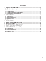
Service code
Outdoor unit
FDCH335CKXE6G-K
~
FDCH1360CKXE6G
Changes
History of service code
blank
D
-
-
blank→D Transfer production place from Japan to Thailand
Page
Service code
blank
D
Specifications / Exterior dimentions / Electric wiring
P4~8
P60~64
Except Specifications, Exterior dimentions and Electrical wiring, this technical manual can be applied for all service code.
'09•KX-T-139
CONTENTS
1 GENERAL INFORMATION ............................................................................... 1
1.1 Specific features............................................................................................ 1
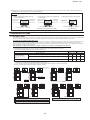
1.2 How to read the model name ........................................................................ 2
1.3 Table of models............................................................................................. 2
1.4 Table of indoor units panel (Option) .............................................................. 2
1.5 Outdoor units combination table ................................................................... 3
2 OUTDOOR UNIT ................................................................................................ 4
2.1 Specifications ................................................................................................ 4
2.2 Exterior dimensions....................................................................................... 6
2.3 Electrical wiring ............................................................................................. 8
2.4 Noise level..................................................................................................... 9
3 PIPING SYSTEM.............................................................................................. 10
4 RANGE OF USAGE & LIMITATIONS ............................................................. 11
5 SELECTION CHART ....................................................................................... 16
6 KX SERIES INSTALLATION MANUAL .......................................................... 28
7 CHECK OPERATION PROCEDURE .............................................................. 52
8 OUTDOOR UNIT (Service code D) ................................................................ 60
8.1 Specifications .............................................................................................. 60
8.2 Exterior dimentions ..................................................................................... 62
8.3 Electrical wiring ........................................................................................... 64
#
'09•KX-T-139
1
GENERAL INFORMATION
1.1 Specific features
(1) The R410A refrigerant is used.
The refrigerant R410A, with an ozone destruction coefficient of zero, is used and the CO2 discharge volume is reduced, In ad
dition, R410A is a pseudo-azeotropic refrigerant, so there is little change in its consistency that would cause it to divide into the
gas and liquid phases, or undergo temperature slide, and it is also possible to add refrigerant on-site.
(2) Height difference from 50m to 100m.
Maximum allowable height difference between the outdoor and the indoor unit located at the lowest height position has
been increased from 50m to 100m.(1) (When the outdoor unit is located at higher position than the indoor unit)
Note (1) In case of less than 50m, the standard models are applied.
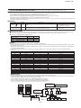
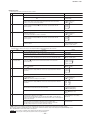
(3) Connectable indoor capacity.
(a) Capacity from 50% to 200% is possible.
Item
Number of connectable
Connectable capacity (2)
FDCH400CKXE6G
to 36 units
200 ~ 800
FDCH450CKXE6G
to 40 units
225 ~ 900
Model
Note (2) When connecting the indoor unit type FDK, FDFL, FDFU or FDFW Series, limit the connectable capacity not higher than
130%.
(b) Capacity from 50% to 160% is possible.
Item
Number of connectable
Connectable capacity(2)
FDCH504CKXE6G
to 36 units
252 ~ 806
FDCH560CKXE6G
to 40 units
280 ~ 896
FDCH65CKXE6G
2 to 44 units
308 ~ 984
FDCH680CKXE6G
2 to 49 units
340 ~ 088
FDCH735CKXE6G
2 to 53 units
368 ~ 76
FDCH800CKXE6G
2 to 58 units
400 ~ 280
FDCH850CKXE6G
2 to 6 units
425 ~ 360
FDCH900CKXE6G
2 to 65 units
450 ~ 440
FDCH960CKXE6G
2 to 69 units
477 ~ 526
Model
Note (2) When connecting the indoor unit type FDK, FDFL, FDFU or FDFW Series, limit the connectable capacity not higher than
130%.
(c) Capacity from 50% to 130% is possible.
Item
Number of connectable
Connectable capacity
FDCH00CKXE6G
2 to 59 units
504 ~ 3
FDCH065CKXE6G
2 to 62 units
532 ~ 384
FDCH30CKXE6G
2 to 66 units
560 ~ 456
FDCH80CKXE6G
3 to 69 units
588 ~ 528
FDCH235CKXE6G
3 to 72 units
65 ~ 599
FDCH300CKXE6G
3 to 76 units
650 ~ 690
FDCH360CKXE6G
3 to 80 units
680 ~ 768
Model
-
-
'09•KX-T-139
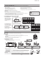
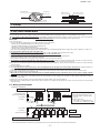
1.2
How to read the model name
Example:
FDCH 400 C KX E 6G
Series code.
Application power source. (See the specifications)
Multi KX series
Cooling only type
Nominal capacity (nominal cooling capacity : 40.0kW)
Model name (Outdoor unit)
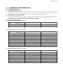
1.3 Table of models
Capacity
22
28
36
45
56
71
90
112
Model
Ceiling cassette-4 way type
(FDT)
Ceiling cassette-4 way compact type
(FDTC)
Ceiling cassette-2 way type
(FDTW)
Ceiling cassette-1 way type
(FDTS)
Ceiling cassette-1 way compact type
(FDTQ)
Duct connected-High static pressure type
(FDU)
Duct connected-Middle static preessure type
(FDUM)
Duct connected (Ultra thin)-Low static preessure type
(FDQS)
Wall-mounted type
(FDK)
Ceiling suspen ded type
(FDE)
Floor standing (with casing) type
(FDFL)
Floor standing (without casing) type
(FDFU)
Floor standing-2 way type
(FDFW)
Duct connected-compact and Flexible type
(FDUH)
Outdoor units to be combined
FDCH335CKXE6G-K, FDCH400CKXE6G ~ 560CKXE6G
FDCH560CKXE6G-K, FDCH615CKXE6G ~ 1360CKXE6G
(FDC)
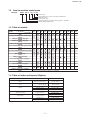
1.4 Table of indoor units panel (Option)
Model
FDTC
FDT
FDTW
Parts Model
Capacity:22,28,36,45,56
Capacity:28,36,45,56,7,
90,2,40,60
Capacity:28,45,56
Capacity:7,90
Capacity:2,40
FDTQ
(Direct blow panel)
Capacity:22,28,36
FDTQ
(Duct panel)
Capacity:22,28,36
FDTS
Capacity: 45
Capacity:7
-
-
TC-PSA-25W-E
T-PSA-36W-E
TW-PSA-24W-E
TW-PSA-34W-E
TW-PSA-44W-E
TQ-PSA-5W-E
TQ-PSB-5W-E
QR-PNA-4W-ER
QR-PNB-4W-ER
TS-PSA-29W-E
TS-PSA-39W-E
140
160
224
280
'09•KX-T-139
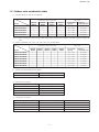
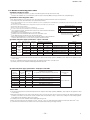
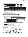
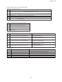
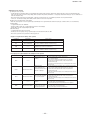
1.5 Outdoor units combination table
(a) Models FDCH735, 800, 850, 900CKXE6G
Item
Combination outdoor unit models
FDCH335
CKXE6G-K
FDCH400
CKXE6G
FDCH800CKXE6G
1
_
FDCH850CKXE6G
_
Connectable (1) Number of
capacity
connectable units
1
FDCH450
CKXE6G
_
FDCH504
CKXE6G
_
368 ~ 1176
2 to 53 unit
2
_
_
400 ~ 1280
2 to 58 unit
1
_
425 ~ 1360
2 to 61 unit
FDCH900CKXE6G
_
1
_
2
_
450 ~ 1440
2 to 65 unit
FDCH960CKXE6G
_
_
1
1
477 ~ 1526
2 to 69 unit
Models
FDCH735CKXE6G
Indoor unit
Note (1) When connecting the indoor unit type FDK, FDFL, FDFU or FDFW Series, limit the connectable capacity not higher than
130%.
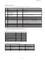
(b) Models FDCH960, 1010, 1065, 1130, 1180, 1235, 1300, 1360CKXE6G
Item
Combination outdoor unit models
FDCH504
CKXE6G
Indoor unit
FDCH1010CKXE6G
2
FDCH560
CKXE6G
_
504 ~ 1311
2 to 59 unit
FDCH1065CKXE6G
1
1
_
_
_
532 ~ 1384
2 to 62 unit
FDCH1130CKXE6G
_
_
_
560 ~ 1456
2 to 66 unit
FDCH1180CKXE6G
_
2
_
_
1
_
588 ~ 1528
3 to 69 unit
FDCH1235CKXE6G
_
_
1
_
2
_
615 ~ 1599
3 to 72 unit
FDCH1300CKXE6G
_
_
_
1
650 ~ 1690
3 to 76 unit
FDCH1360CKXE6G
_
_
_
1
_
2
680 ~ 1768
3 to 80 unit
Models
FDCH560
CKXE6G-K
_
FDCH615
CKXE6G
_
FDCH680
CKXE6G
_
Connectable
capacity
Number of
connectable units
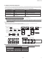
(c) Outdoor unit side branch pipe set (Option)
Outdoor unit
Branch pipe set
For two units (for FDCH 735CKXE6G ~ 1360CKXE6G)
DOS-2A-1
Note (1) Be sure to use this when combining units.
(d) Branch pipe set (Option)
Total capacity downstream
Branching pipe set
Less than 180
DIS-22-1
180 or more but less than 371
DIS-180-1
371 or more but less than 540
DIS-371-1
540 or more
DIS-540-2
(e) Header pipe set (Option)
Total capacity downstream
Header set model type
Number of branches
Less than 180
HEAD4-22-1
4 branches at the most
180 or more but less than 371
HEAD6-180-1
6 branches at the most
371 or more but less than 540
HEAD8-371-1
8 branches at the most
540 or more
HEAD8-540-2
8 branches at the most
-
-
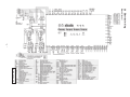
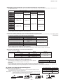
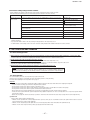
2 OUTDOOR UNIT
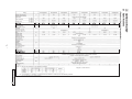
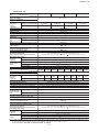
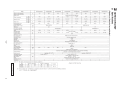
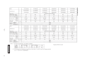
2.1 Specifications
• Single use (Used also for combination)
94㧛94
94㧛94
93㧛93
93㧛93
93㧛93
93㧛93
93㧛93
-
-
External static pressure
Pa
Max 50
%
94㧛94
Power factor
'09•KX-T-139
PCB003Z138 a
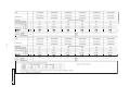
• Combination use
%
93㧛93
93㧛93
93㧛93
93㧛93
93㧛93
93㧛93
Power factor
%
93㧛93
93㧛93
93㧛93
94㧛94
94㧛94
94㧛94
-
Power factor
'09•KX-T-139
PCB003Z138 a
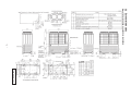
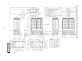
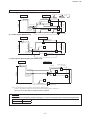
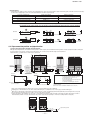
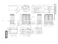
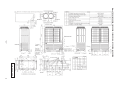
2.2 Exterior dimensions
Models FDCH335CKXE6G-K, 400CKXE6G, 450CKXE6G
-
-
'09•KX-T-139
PCB003Z141
-
Models FDCH504CKXE6G, 560CKXE6G, 560CKXE6G-K, 615CKXE6G, 680CKXE6G
-
'09•KX-T-139
PCB003Z142
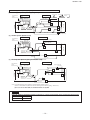
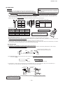
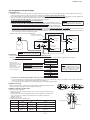
2.3 Electrical wiring
Models All model
-
-
'09•KX-T-139
PCB003Z139
'09•KX-T-139
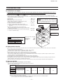
2.4 Noise level
Measured based on JIS B 8616
Mike position as highest noise level in position as below
Distance from front side1m
Height1m
Model FDCH400CKXE6G
Noise level 59.5 dB (A)
N80
N70
60
N60
50
70
60
50
N50
40
30
40
125
250
500
70
N70
60
N60
50
1000
2000
4000
40
63
N70
N60
50
80
70
60
50
N50
40
30
40
125
250
500
1000
2000
4000
30
8000
MidOctaveBandFrequency(Hz)
Model FDCH680CKXE6G
Noise level 65 dB (A)
80
SouudPressureLevel
(standard2x10-5pa)
500
N70
60
N60
50
125
250
500
1000
N70
60
N60
50
50
40
30
80
50
40
50
40
63
40
250
500
80
70
60
4000
30
8000
MidOctaveBandFrequency(Hz)
-
-
125
250
500
1000
2000
1000
2000
4000
30
8000
80
80
70
70
N70
60
60
N60
50
50
N50
40
40
N40
N30
125
N40
N3
0
N80
N50
63
60
N50
N80
60
30
70
Model FDCH615CKXE6G
Noise level 64.5 dB (A) N60
N40
2000
70
80
MidOctaveBandFrequency(Hz)
60
40
63
30
8000
70
50
40
30
4000
N70
N50
N3
0
2000
4000
MidOctaveBandFrequency(Hz)
N80
70
1000
70
N40
N3
0
63
250
Models FDCH560CKXE6G
560CKXE6G-K
Noise level 63 dB (A)
80
SouudPressureLevel
(standard2x10-5pa)
SouudPressureLevel
(standard2x10-5pa)
N80
60
125
N80
MidOctaveBandFrequency(Hz)
Model FDCH504CKXE6G
Noise level 61.5 dB (A)
70
60
80
N40
N3
0
MidOctaveBandFrequency(Hz)
80
70
50
40
30
30
8000
80
N50
N40
N3
0
63
N80
SouudPressureLevel
(standard2x10-5pa)
70
80
80
SouudPressureLevel
(standard2x10-5pa)
SouudPressureLevel
(standard2x10-5pa)
80
Model FDCH450CKXE6G
Noise level 62.5 dB (A)
SouudPressureLevel
(standard2x10-5pa)
Model FDCH335CKXE6G-K
Noise level 59 dB (A)
30
8000
N40
N30
30
63
125
250
500
1000
2000
4000
MidOctaveBandFrequency(Hz)
30
8000
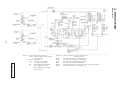
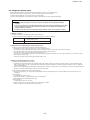
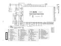
3 PIPING SYSTEM
Models All model
-
10 ThI-R1, R2 : Cooling operation : Frost prevention control.
Super heat control.
ThI-R3 :
For super heat control of cooling operation.
Tho-D :
For control of discharge pipe temperature.
Tho-C :
For control of temperarure under the dome.
Tho-S :
For control of suction pipe temperature.
Tho-SC :
Electronic expansion valve (EEVSC) control of cooling operation.
Tho-H :
For super heat control of sub-cooling coil.
'09•KX-T-139
PCB003Z140
Notes (1) Preset point of protective deviees
63H1-1 : Open 4.15MPa, Close 3.15MPa
(For protection)
(2) Function of thermistor
PSH :
For compressor control
Cooling: 3.70 ON (MPa)
PSL :
ON 0.18MPa, OFF 0.20MPa
(For compressor control)
ON 0.134MPa, OFF 0.18MPa
(For protection)
'09•KX-T-139
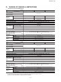
4
RANGE OF USAGE & LIMITATIONS
• Single use (also for combined use)
System
Item
Indoor air temperature
(Upper, lower limits)
FDCH400CKXE6G
FDCH450CKXE6G
Refer to page 15
Outdoor air temperature
(Upper, lower limits)
Indoor units
that can be
used in
combination
Total piping length
Number of connected units
1 to 36 unit
1 to 40 unit
1 to 36 unit
Connectable capacity (1)
200 ~ 800
225 ~ 900
252 ~ 806
(2)
1000m or less
Main pipe length
130m or less
Single direction piping length
Actual length : 160m or less, Eguivalent length : 185m or less
Allowable pipe length from the first branching
90m or less (However, difference between the longest and shortest piping : 40m or less)
Elevation difference between the first branching point and the indoor unit
18m or less
Difference in
height between
indoor and outdoor
units
50 ~100m(3)
Outdoor unit is higher
Prohibited activity
Outdoor unit is lower
18m or less
Difference in the elevation of indoor units in a system
Indoor unit atmosphere (behind ceiling)
temperature and humidity
Only models FDT, FDTC, FDTW, FDTS, FDTQ,
FDU, FDUM, FDQS, FDUH
Dew point temperature 28 or less, relative humidity 80% or less
(FDE, FDK, FDFL, FDFU : Dew point temperature 23 or less, relative humidity 80% or less)
6 min or more (3 minutes or more from start to stop or 3 minutes or more from stop to start)
1 cycle time
3 min or more
Stop time
Within 10% of rated voltage
Voltage drop during start
Within 15% of rated voltage
Phase unbalance
Within
MAX. 90m
Number of connected units
1 to 40 unit
Connectable capacity (1)
280 ~ 896
Single direction piping length
First branch
Allowable pipe length from the first branching
2 to 44 unit
1000m or less
90m or less (However, difference between the longest and shortest piping : 40m or less)
18m or less
MAX. 90m
(3)
(Lowest
indoor unit)
50~100m
Prohibited activity
Indoor unit
18m or less
Difference in the elevation of indoor units in a system
Stop time
Dew point temperature 28 or less, relative humidity 80% or less
(FDE, FDK, FDFL, FDFU : Dew point temperature 23 or less, relative humidity 80% or less)
MAX. 18m
(Header)
(Highest indoor unit)
6 min or more (3 minutes or more from start to stop or 3 minutes or more from stop to start)
3 min or more
MAX. 18m
Power source
voltage
1 cycle time
MAX. 130m
Compressor
stop/start
frequency
50~100m
Indoor unit atmosphere (behind ceiling)
temperature and humidity
Only models FDT, FDTC, FDTW, FDTS, FDTQ,
FDU, FDUM, FDQS, FDUH
340 ~ 1088
130m or less
Actual length : 160m or less, Eguivalent length : 185m or less
Outdoor unit is higher
Outdoor unit is lower
Outdoor unit
2 to 49 unit
308 ~ 984
Elevation difference between the first branching point and the indoor unit
Difference in
height between
indoor and outdoor
units
denotes
(Highest indoor unit)
MAX. 130m
(2)
FDCH680CKXE6G
Refer to page15
MAX. 18m
50~100m
Total piping length
FDCH615CKXE6G
Indoor unit
Outdoor air temperature
(Upper, lower limits)
Indoor units
that can be
used in
combination
FDCH560CKXE6G
MAX. 18m
System
Item
Indoor air temperature
(Upper, lower limits) Outdoor unit
3% of rated voltage
MAX. 18m
Power source
voltage
Voltage fluctuation
MAX. 18m
Compressor
stop/start
frequency
Main pipe length
FDCH504CKXE6G
Within 10% of rated voltage
Voltage fluctuation
First branch
Within 15% of rated voltage
Voltage drop during start
(Lowest indoor unit)
Within
Phase unbalance
3% of rated voltage
MAX. 90m
Note (1) When connecting the indoor unit type FDK, FDFL, FDFU or FDFW (not yet) Series, limit the connectable capacity not higher than 130%.
(2) When the pipe extension length exceeds 510 m, additional refrigerant oil must be charged (1,000 cc).
(3) In case of less than 50m, the standard models are applied.
Outdoor unit
Indoor unit
-
11 -
MAX. 90m (2)
denotes
MAX. 40m (2)
(Highest indoor unit)
Compressor
stop/start
frequency
6 min or more (3 minutes or more from start to stop or 3 minutes or more from stop to start)
1 cycle time
Power source
voltage
'09•KX-T-139
3 min or more
Stop time
Voltage fluctuation
Within 10% of rated voltage
Voltage drop during start
Within 15% of rated voltage
Phase unbalance
Within
3% of rated voltage
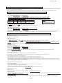
Allowable length of refrigerant piping, height difference between indoor and outdoor unit
(1) Branch pipe System (Branch piping used)
Outdoor unit
Indoor unit
denotes
MAX. 40m (2)
MAX. 18m
MAX. 130m
First branch
MAX. 90m
(Lowest indoor unit)
(2) Header System (Header used)
Outdoor unit
MAX. 18m
(Highest indoor unit)
MAX. 18m
50~100m (3)
MAX. 90m (2)
Indoor unit
MAX. 40m (2)
MAX. 18m
MAX. 18m
(Header)
MAX. 18m
MAX. 130m
50~100m (3)
(Highest indoor unit)
First branch
(Lowest indoor unit)
MAX. 90m (2)
(3) Mixed System (Branch piping and Header used)
Outdoor unit
Indoor unit
(Highest indoor unit)
MAX.40m(2)
Ⅱ
Ⅲ
First branch
(Header)
Ⅴ
MAX.90m(2)
Ⅳ
MAX.18m
50~100m (3)
MAX.18m
Ⅰ
MAX.130m
MAX.18m
MAX.90m(2)
Ⅵ
(Lowest indoor unit)
Note (1) A branch piping system cannot be connected after a header system.
(2) 90m or less (However, difference between the longest and shortest piping : 40m or less)
(3) In case of less than 50m, the standard models are applied.
Important
When the Additional refrigerant quantity for piping (P) is over the following table, please separate the refrigerant line.
Outdoor unit
P (kg)
400-680
50
-
12 -
'09•KX-T-139
• Combination use
System
Item
Indoor air temperature
(Upper, lower limits)
FDCH735CKXE6G
FDCH800CKXE6G
Number of connected units
2 to 53 units
2 to 58 units
2 to 61 units
2 to 65 units
Connectable capacity (1)
368 ~ 1176
400 ~ 1280
425 ~ 1360
450 ~ 1440
Total piping length (2)
1000m or less
Single direction piping length
Actual length : 160m or less, Equival length : 185m or less
130m or less
Main pipe length
90m or less (However, difference between the longest and shortest piping : 40m or less)
Allowable pipe length from the first branching
18m or less
Elevation difference between the first branching point and the indoor unit
Difference in
height between
indoor and outdoor
units
Outdoor unit is higher
50~100m(3)
Outdoor unit is lower
Prohibited activity
Difference in the elevation of indoor units in a system
18m or less
Difference in height between outdoor units
(Same system)
MAX. 0.4m
Difference between an outdoor unit and
on outdoor unit side branch pipe
MAX. 5m
Length of oil equalization piping
MAX. 10m
Indoor unit atmosphere (behind ceiling)
temperature and humidity
Only models FDT, FDTC, FDTW, FDTS, FDTQ,
FDU, FDUM, FDQS, FDUH
Compressor
1 cycle time
stop/start
Stop time
frequency
Power source
voltage
FDCH900CKXE6G
Refer to page 15
Outdoor air temperature
(Upper, lower limits)
Indoor units
that can be
used in
combination
FDCH850CKXE6G
Dew point temperature 28 or less, relative humidity 80% or less
(FDE, FDK, FDFL, FDFU : Dew point temperature 23 or less, relative humidity 80% or less)
6 min or more (3 minutes or more from start to stop or 3 minutes or more from stop to start)
3 min or more
Voltage fluctuation
Within 10% of rated voltage
Voltage drop during start
Within 15% of rated voltage
Phase unbalance
Within
3% of rated voltage
System FDCH960 FDCH1010 FDCH1065 FDCH1130 FDCH1180 FDCH1235 FDCH1300 FDCH1360
CKXE6G CKXE6G CKXE6G CKXE6G CKXE6G CKXE6G CKXE6G CKXE6G
Item
Indoor air temperature (Upper, lower limits)
Refer to page15
Outdoor air temperature (Upper, lower limits)
Outdoor unit
Indoor unit
denotes
Oil
equalization
(1)
2 to 69
2 to 59
2 to 62
2 to 66
3 to 69
3 to 72
3 to 76
3 to 80
Indoorpiping
units
Outdoor of connected units
Number
unit 1
units
units
units
units
units
units
units
units
that can be
MAX. 130m
MAX.
90m
used in
MAX. capacity
5m
(Highest
indoor
unit)
Connectable
477
~
1526
504
~
1311
532
~
1384
560
~
1456
588
~
1528
615
~
1599
650
~
1690
680
~ 1768
combination
MAX. 18m
MAX. 5m
MAX. 10m
90m or less (However, difference between the longest and shortest piping : 40m or less)
Allowable pipe length from the first branching
18m or less
Elevation difference between the firstOutdoor
branching
point and the indoor unit
unit
Difference in
height between
indoor and outdoor
units
side branch
First branch
(DOS-2A-1)
Outdoor
unit is higher
50~100m(3)
Outdoor unit is lower
Prohibited activity
MAX. 90m
(Lowest indoor unit)
Difference in the elevation of indoor units in a system
Difference in height between outdoor units
(Same system)
Outdoor unit
Difference
between an outdoor unit and
Oil equalization
Outdoor
piping unit side branch pipe
on outdoor
unit 1
Length of oil equalization
MAX. 5m
(Highest indoor unit)
MAX. 10m
Dew point temperature 28 or less, relative humidity 80% or less
(FDE, FDK, FDFL, FDFU : Dew point temperature 23 or less, relative humidity 80% or less)
MAX. 18m
MAX. 0.4m
50~100m
MAX. 0.4m
Indoor unit
Indoor unit atmosphere (behind ceiling)
temperature and humidity
Outdoor
unit 2 FDTQ,
Only models FDT, FDTC, FDTW, FDTS,
MAX. 5m
FDU, FDUM, FDQS, FDUH
MAX. 10m
Compressor
1 cycle time
stop/start
Stop
time
frequency
Outdoor unit
Power source
voltage
18m or less
MAX. 130m
piping
MAX. 5m
side branch
First branch
Voltage
fluctuation
(DOS-2A-1)
MAX. 18m
Actual length : 160m or less, Equival length : 185m or less
130m or less
MAX. 18m
MAX. 0.4m
50~100m
Main pipe length
1000m or less
Outdoor
unit 2
MAX. 18m
Single direction piping length
6 min or more (3 minutes or more from start to stop or 3 minutes or more from stop to start)
3 min or more
Within
10% of rated voltage
Within
15% of rated voltage
(Lowest indoorWithin
unit)
3% of rated voltage
(Header)
Voltage drop during start
Phase unbalance
MAX. 18m
Total piping length (2)
Note (1) When connecting the indoor unit type FDK, FDFL, FDFU orMAX.
FDFW
90m (not yet) Series, limit the connectable capacity not higher than 130%.
(2) When the pipe extension length exceeds 510 m, additional refrigerant oil must be charged (1,000 cc).
(1) of
A branch
piping50m,
systemthe
cannot
be connected
after aare
header
system.
(3) InNote
case
less than
standard
models
applied.
Oil equalization
piping
Outdoor unit
Outdoor
unit 1
MAX. 130m
MAX. 5m
13 -
Indoor unit
MAX. 90m (2)
denotes
MAX. 40m
(2)
(Highest indoor unit)
FDU, FDUM, FDQS, FDUH
Compressor
1 cycle time
stop/start
Stop time
frequency
Power source
voltage
6 min or more (3 minutes or more from start to stop or 3 minutes or more from stop to start)
'09•KX-T-139
3 min or more
Voltage fluctuation
Within
10% of rated voltage
Voltage drop during start
Within
15% of rated voltage
Phase unbalance
Within
3% of rated voltage
Allowable length of refrigerant piping, height difference between indoor and outdoor unit
(1) Branch pipe System (Branch piping used)
Outdoor unit
Indoor unit
MAX. 130m
MAX. 5m
denotes
MAX. 40m (2)
MAX. 90m (2)
(Highest indoor unit)
MAX. 18m
Outdoor
unit 2
Outdoor unit
side branch
(DOS-2A-1)
MAX. 18m
MAX. 10m
MAX. 0.4m
50~100m (3)
MAX. 5m
First branch
MAX. 90m
(Lowest indoor unit)
(2) Header System (Header used)
Outdoor unit
Oil equalization
piping
Outdoor
unit 1
Indoor unit
MAX. 40m (2)
MAX. 130m
MAX. 5m
(Highest indoor unit)
First branch
MAX. 18m
MAX. 18m
MAX. 10m
MAX. 0.4m
50~100m (3)
Outdoor
unit 2
MAX. 5m
Outdoor unit
side branch
(DOS-2A-1)
MAX. 18m
Outdoor
unit 1
MAX. 18m
Oil equalization
piping
(Header)
(Lowest indoor unit)
MAX. 90m (2)
NoteSystem
(1) A branch
piping system
cannotand
be connected
afterused)
a header system.
(3) Mixed
(Branch
piping
Header
Outdoor unit
Ⅱ
Ⅲ
MAX. 0.4m
MAX. 5m
MAX. 10m
(Header)
Outdoor unit
side branch
(DOS-2A-1)
First branch
MAX.18m
Ⅰ
Outdoor
unit 2
50~100m (3)
(Highest indoor unit)
MAX.40m(2)
MAX.90m(2)
MAX. 130m
MAX. 5m
Ⅴ
Ⅳ
MAX.18m
Outdoor
unit 1
Indoor unit
MAX.18m
Oil equalization
piping
Ⅵ
MAX.90m(2)
(Lowest indoor unit)
Note (1) A branch piping system cannot be connected after a header system.
(2) 90m or less (However, difference between the longest and shortest piping : 40m or less)
(3) In case of less than 50m, the standard models are applied.
Important
When the Additional refrigerant quantity for piping (P) is over the following table, please separate the refrigerant line.
Outdoor unit
P (kg)
735-1360
100
-
14 -
'09•KX-T-139
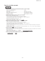
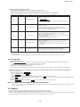
Operating temperature range
Outdoor air temperature (˚C D.B.)
Cooling operation
Applicable range
43
40
35
30
25
20
26
24
0
-5
14
16
Indoor air temperature (˚C W.B.)
-
15 -
18
20
22
'09•KX-T-139
5
SELECTION CHART
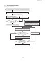
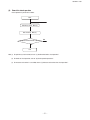
(1) Equipment selection flow
Calculate the load for each room separately, then determine the indoor load.
Select an indoor unit that matches the indoor load (tentative).
Calculate the temperature compensation,
then calculate the indoor unit capacity.
(See item (2) (a) for the calculation method.)
Indoor unit
capacity (tentative)
Indoor Load
Change the indoor unit.
Select the outdoor unit (tentative).
NO
Calculate temperature compensation and piping
compensation, etc., then calculate the outdoor unit
capacity. (See item (2) (b) for the calculation method.)
YES
Calculate the total indoor unit capacity.
Calculate the system capacity
(See item (2) (c) for the calculation method.)
NO
Total indoor unit
capacity System Capacity
Change the outdoor unit.
YES
Calculate the indoor unit capacity.
(See item (2) (d) for the calculation method.)
Indoor unit
capacity Indoor Load
YES
Equipment selection complete.
-
16 -
NO
'09•KX-T-139
(2) Capacity calculation method
(a) Calculating the indoor unit capacity compensation
Indoor unit capacity = Indoor unit total rated capacity
× Capacity compensation coefficient according to temperature conditions
See item (3) (a) concerning the capacity compensation coefficient according to temperature conditions.
(b) Calculating the outdoor unit capacity compensation
Outdoor Unit Capacity
= Outdoor unit rated capacity (rated capacity when 100% connected)
× Capacity compensation coefficient according to temperature conditions
× Capacity compensation coefficient according to piping length
× Capacity compensation coefficient according to indoor unit connection capacity
See item (3) (a) concerning the capacity compensation coefficient according to temperature conditions.
See item (3) (b) concerning the capacity compensation coefficient according to piping length.
See item (3) (c) concerning the capacity compensation coefficient according to indoor unit connected capacity.
This compensation should be carried out only in cases where the indoor unit total capacity is 100% or higher.
(c) Calculating system capacity
Compare the capacities determined in items (a) and (b) above and let the smaller value be the system capacity.
In cases where indoor unit total capacity > outdoor unit capacity
System capacity = Outdoor unit capacity
In cases where indoor unit total capacity < outdoor unit capacity
System capacity = Indoor unit capacity
(d) Calculating indoor unit capacity [item (c) 1 only]
Indoor unit capacity = System capacity × [(Indoor unit capacity) / (Indoor unit total capacity)]
-
17 -
'09•KX-T-139
Capacity calculation example
Example
Cooling (when the indoor unit connected total capacity is 100% or higher)
• Outdoor unit FDCH450CKXE6G................................................ 1 Unit
• Indoor unit FDT56KXE6A.......................................................... 10 Units
• Piping length ............................................................................... 100 m (Equivalent length)
• Indoor, outdoor unit height difference......................................... 70 m (Outdoor unit is higher)
• Temperature conditions ............................................................... Outdoor temperature: 35˚C DB
• Temperature conditions................................................................ Indoor temperature: 18˚C WB
<Indoor unit total cooling capacity>: Item (2) (a) calculation.
• Indoor unit rated cooling capacity: 5.6 kW
• Capacity compensation coefficient according to temperature conditions:
0.95 (Calculated according to Indoor 18˚C WB / Outdoor 35˚C DB); (See page 19)
.
Indoor unit cooling capacity: 5.6 kW × 0.95 =. 5.3 kW
• Indoor unit total cooling capacity calculation;
.
indoor unit total cooling capacity: 5.3 kW × 10 units =. 53.0 kW
<Outdoor unit maximum cooling capacity> : Item (2) (b) calculation
• Outdoor unit rated cooling capacity: 45.0 kW
• Capacity compensation coefficient according to temperature conditions:
0.95 (Calculated according to Indoor 18˚C WB / Outdoor 35˚C DB); (See page 19)
.
Outdoor unit cooling capacity: 45.0 kW × 0.95 =. 42.8 kW
• Capacity compensation coefficient according to piping length: 0.95 (calculated according to 100 m length); (See page 20)
.
42.8 kW × 0.95 =. 40.7 kW
.
• Capacity compensation coefficient according to indoor unit connected total capacity: 1.05 ← (56 × 10) / 450 =. 124%) (See page 23)
..
40.7 kW × 1.05 = 42.7 kW
<System cooling capacity>: Item (2) (c) calculation
Compare the indoor unit total cooling capacity and the outdoor unit maximum cooling capacity. The smaller value is the actual
system cooling capacity.
• Indoor unit total cooling capacity
: 53.0 kW ⇨ System cooling capacity: 42.7 kW
• Outdoor unit maximum cooling capacity: 42.7 kW
<Indoor unit cooling capacity Compensation>: Item (2) (d) calculation.
42.7 kW × 5.3 kW .
=. 4.3 kW
53.0 kW
-
18 -
'09•KX-T-139
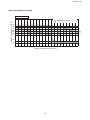
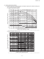
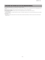
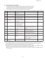
(3) Capacity compensation coefficient
(a) Capacity compensation coefficient and power consumption compensation coefficient according to indoor and outdoor temperature conditions.
1) Capacity compensation coefficient
1.40
Indoor air W.B. temperature 24˚CWB
1.35
Indoor air W.B. temperature 26˚CWB
Capacity compensation conefficient
1.30
1.25
Indoor air W.B. temperature 22˚CWB
1.20
Indoor air W.B. temperature 21˚CWB
1.15
1.10
Indoor air W.B. temperature 20˚CWB
1.05
Indoor air W.B. temperature 19˚CWB
1.00
0.95
Indoor air W.B. temperature 18˚CWB
0.90
Indoor air W.B. temperature 17˚CWB
0.85
0.80
Indoor air W.B. temperature 16˚CWB
Indoor air W.B. temperature 15˚CWB
0.75
0.70
Indoor air W.B. temperature 14˚CWB
0
2
4
6
8
10
12
14
16
18
20
22
24
26
28
30
32
34
36
38
40
42
Outdoor air D.B. temperature (˚CDB)
Note (1) The above-mentioned table shows a typical condition among conditions to occur via controlling an air-conditioning equipment.
2) Power consumption correction factor
1.25
Power consumption compensation coefficient
1.25
1.20
1.15
Indoor air W.B. temperature 26˚CWB
1.10
Indoor air W.B. temperature 24˚CWB
1.05
1.00
Indoor air W.B. temperature 22˚CWB
0.95
Indoor air W.B. temperature 21˚CWB
0.90
0.85
Indoor air W.B. temperature 20˚CWB
0.80
Indoor air W.B. temperature 19˚CWB
0.75
Indoor air W.B. temperature 18˚CWB
0.70
0.65
Indoor air W.B. temperature 17˚CWB
0.60
Indoor air W.B. temperature 16˚CWB
0.55
0.50
Indoor air W.B. temperature 15˚CWB
0
2
4
6
8
Indoor air W.B. temperature 14˚CWB
10 12 14 16 18 20 22 24 26 28 30 32 34 36 38 40 42
Outdoor air D.B. temperature(˚CDB)
Note (1) The above-mentioned table shows a typical condition among conditions to occur via controlling an air-conditioning equipment.
-
19 -
'09•KX-T-139
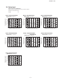
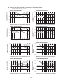
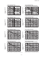
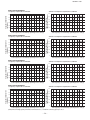
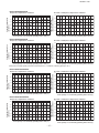
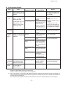
(b) Correction of capacity in relation to one way length of refrigerant piping.
(Note) This table is for reference only. If the refrigerant piping one way equivalent after the first branch is extended longer than 40 m, it could
drop further by about 10% in the worst case.
Model FDCH400CKXE6G
*
Gas pipe: 28.58
0.95
Gas pipe: 25.4
0.90
0.85
0.80
0
20
40
60
80
100
120
140
160
Model FDCH450CKXE6G
1.00
Capacity compensation
coefficient
Capacity compensation
coefficient
1.00
Gas pipe: 31.8
0.95
Gas pipe: 28.58
0.90
0.85
0.80
180
0
Refrigerant piping one way equivalent length (m)
0.95
Gas pipe: 28.58
0.90
0.85
0
20
40
60
180
Gas pipe: 28.58
0.85
0
20
40
60
80 90100 120 140 160 180
Refrigerant piping one way equivalent length (m)
Model FDCH680CKXE6G
Gas pipe: 31.8
0.95
Gas pipe: 28.58
0.90
0.85
20
40
60
Capacity compensation
coefficient
Capacity compensation
coefficient
160
1.00
0.80
0
Gas pipe: 31.8
0.95
0.85
0.80
0
80 90100 120 140 160 180
Gas pipe: 31.8
0.90
Gas pipe: 34.92*
0.85
20
40
60
60
80 90 100 120 140 160 180
1.00
Gas pipe: 38.1
0.95
Gas pipe: 31.8
0.90
Gas pipe: ø34.92*
0.85
0.80
80 90100 120 140 160 180
Refrigerant piping one way equivalent length (m)
0
20
40
60
80 90 100
120
140
160
180
Refrigerant piping one way equivalent length (m)
Note (1) Parts with the * mark show the piping size in case used in Europe.
-
40
Model FDCH800CKXE6G
(FDCH400CKXE6G + FDCH400CKXE6G)
Capacity compensation
coefficient
0.95
20
Refrigerant piping one way equivalent length (m)
Model FDCH735CKXE6G
(FDCH335CKXE6G-K + FDCH400CKXE6G)
Gas pipe: 38.1
Gas pipe: 28.58
0.90
Refrigerant piping one way equivalent length (m)
Capacity compensation
coefficient
140
0.90
Model FDCH615CKXE6G
0
120
Gas pipe: 31.8
0.80
80 90100 120 140 160 180
1.00
0.80
80 90 100
0.95
Refrigerant piping one way equivalent length (m)
1.00
60
1.00
Gas pipe: 31.8
0.80
40
Model FDCH560CKXE6G
Model FDCH504CKXE6G
Capacity compensation
coefficient
Capacity compensation
coefficient
1.00
20
Refrigerant piping one way equivalent length (m)
20 -
'09•KX-T-139
Model FDCH850CKXE6G
(FDCH400CKXE6G + FDCH450CKXE6G)
1.00
Gas pipe: 31.8
0.90
0.85
Gas pipe: 34.92*
0
40
60
Gas pipe: 31.8
0.85
Gas pipe: 34.92*
0
1.00
*
Gas pipe: 34.92
Gas pipe: 31.8
0.85
80 90 100
120
140
160
180
20
40
60
0.95
Gas pipe: 38.1
0.90
*
Gas pipe: 34.92
0.85
0.80
0
80 90100 120 140 160 180
20
40
60
80
100 120 140 160 180
Refrigerant piping one way equivalent length (m)
Refrigerant piping one way equivalent length (m)
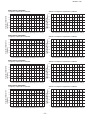
Model FDCH1065CKXE6G
(FDCH504CKXE6G + FDCH560CKXE6G)
Model FDCH1130CKXE6G
(FDCH560CKXE6G + FDCH560CKXE6G)
1.00
0.95
Gas pipe: 38.1
0.90
*
Gas pipe: 34.92
0.85
0
20
40
60
80
*
Gas pipe: 34.92
0.85
0
20
40
60
80
*
Gas pipe: 34.92
0.85
20
40
60
80
100 120 140 160 180
Refrigerant piping one way equivalent length (m)
Note (1)Parts with the * mark show the piping size in case used in Europe.
21 -
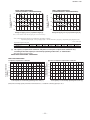
Model FDCH1235CKXE6G
(FDCH615CKXE6G + FDCH615CKXE6G)
0.95
Gas pipe: 38.1
0.90
*
Gas pipe: 34.92
0.85
0.80
100 120 140 160 180
-
0.90
1.00
Capacity compensation
coefficient
Gas pipe: 38.1
0.90
Gas pipe: 38.1
Refrigerant piping one way equivalent length (m)
Model FDCH1180CKXE6G
(FDCH560CKXE6G-K + FDCH615CKXE6G)
0.95
0.95
0.80
0
100 120 140 160 180
Refrigerant piping one way equivalent length (m)
0.80
60
Model FDCH1010CKXE6G
(FDCH504CKXE6G + FDCH504CKXE6G)
0.90
1.00
40
Model FDCH960CKXE6G
(FDCH450CKXE6G + FDCH504CKXE6G)
0.95
0.80
20
Refrigerant piping one way equivalent length (m)
0.80
0
Capacity compensation
coefficient
0.90
0.80
80 90 100 120 140 160 180
Gas pipe: 38.1
1.00
Gas pipe: 38.1
0.95
Refrigerant piping one way equivalent length (m)
1.00
Capacity compensation
coefficient
20
Capacity compensation
coefficient
0.80
Capacity compensation
coefficient
Capacity compensation
coefficient
Gas pipe: 38.1
0.95
Capacity compensation
coefficient
Capacity compensation
coefficient
1.00
Model FDCH900CKXE6G
(FDCH450CKXE6G + FDCH450CKXE6G)
0
20
40
60
80
100 120 140 160 180
Refrigerant piping one way equivalent length (m)
'09•KX-T-139
Model FDCH1360CKXE6G
(FDCH680CKXE6G + FDCH680CKXE6G)
1.00
Capacity compensation
coefficient
Capacity compensation
coefficient
1.00
Model FDCH1300CKXE6G
(FDCH615CKXE6G + FDCH680CKXE6G)
0.95
Gas pipe: 38.1
0.90
*
Gas pipe: 34.92
0.85
0.80
0
20
40
60
80
0.95
Gas pipe: 38.1
0.90
*
Gas pipe: 34.92
0.85
0.80
100 120 140 160 180
Refrigerant piping one way equivalent length (m)
0
20
40
60
80
100 120 140 160 180
Refrigerant piping one way equivalent length (m)
Note (1)Parts with the * mark show the piping size in case used in Europe.
Note (2) Equivalent piping length can be obtained by calculating as follows.
Equivalent piping length = Real gas piping length + Number of bends in gas piping × Equivalent piping length of bends.
Unit : m/one part
Equivalent length of each joint
φ5.88
0.25
φ9.05
0.30
φ22.22
0.35
φ25.4
0.40
φ28.58
0.45
φ3.8
0.55
φ34.92
0.60
φ38.
0.65
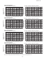
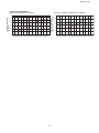
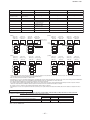
(c) The capacity compensation coefficient and power consumption compensation coefficient vary
according to the total capacity of concurrently operating indoor units, as shown below.
(Note) This table shows typical values.
Model FDCA140HKXEN4A, 140HKXES4A
◆ Capacity compensation coefficient
◆ Capacity compensation coefficient
.2
1.2
.0
1.0
0.8
0.8
0.6
0.6
0.4
0.4
0.2
0.2
0
0
20
40
60
80
00
20
0
0 Total capacity
20
40
60
80
100
120(%)
of concurrently
operating
indoor
unit
Total capacity of concurrently operating indoor unit (%)
Heating
◆ Power consumption compensation coefficient
1.2.2
Power consumption
Capacity compensation
compensation
coefficient
coefficient
Capacity
compensation
Capacity
compensation
coefficient
coefficient
Model
FDCH400CKXE6G
Cooling
1.0.0
0.8
0.8
0.6
0.6
0.4
0.4
0.2
0.2
0
0
20
40
60
80
00
20
0
0 Total
20capacity
40of concurrently
60
80
100
120 (%)
operating
indoor unit
Total capacity of concurrently operating indoor unit (%)
(Note) If the connecting capacity of the indoor unit exceeds 130 %, consider the connecting capacity as 130 %.
-
22 -
'09•KX-T-139
Model FDCH450CKXE6G
◆ Power consumption compensation coefficient
1.2
◆ Capacity compensation coefficient
Power consumption
compensation coefficient
Capacity compensation
coefficient
1.2
1.0
0.8
0.6
0.4
0.2
0
0
1.0
0.8
0.6
0.4
0.2
0
20
40
60
80
100
120
Total capacity of concurrently operating indoor unit (%)
0
20
40
60
80
100
120
Total capacity of concurrently operating indoor unit (%)
Model FDCH504CKXE6G
◆ Power consumption compensation coefficient
1.2
◆ Capacity compensation coefficient
Power consumption
compensation coefficient
Capacity compensation
coefficient
1.2
1.0
0.8
0.6
0.4
0.2
0
0
1.0
0.8
0.6
0.4
0.2
0
20
40
60
80
100
120
Total capacity of concurrently operating indoor unit (%)
0
20
40
60
80
100
120
Total capacity of concurrently operating indoor unit (%)
Model FDCH560CKXE6G
◆ Power consumption compensation coefficient
1.2
◆ Capacity compensation coefficient
Power consumption
compensation coefficient
Capacity compensation
coefficient
1.2
1.0
0.8
0.6
0.4
0.2
0
0
1.0
0.8
0.6
0.4
0.2
0
20
40
60
80
100
120
Total capacity of concurrently operating indoor unit (%)
0
20
40
60
80
100
120
Total capacity of concurrently operating indoor unit (%)
Model FDCH615CKXE6G
◆ Power consumption compensation coefficient
1.2
◆ Capacity compensation coefficient
Power consumption
compensation coefficient
Capacity compensation
coefficient
1.2
1.0
0.8
0.6
0.4
0.2
0
0
20
40
60
80
100
120
Total capacity of concurrently operating indoor unit (%)
1.0
0.8
0.6
0.4
0.2
0
0
20
40
(Note) If the connecting capacity of the indoor unit exceeds 130 %, consider the connecting capacity as 130 %.
-
23 -
60
80
100
120
Total capacity of concurrently operating indoor unit (%)
'09•KX-T-139
Model FDCH680CKXE6G
◆ Power consumption compensation coefficient
1.2
◆ Capacity compensation coefficient
Power consumption
compensation coefficient
Capacity compensation
coefficient
1.2
1.0
0.8
0.6
0.4
0.2
0
0
1.0
0.8
0.6
0.4
0.2
0
20
40
60
80
100
120
Total capacity of concurrently operating indoor unit (%)
0
20
40
60
80
100
120
Total capacity of concurrently operating indoor unit (%)
Model FDCH735CKXE6G
◆ Power consumption compensation coefficient
1.2
◆ Capacity compensation coefficient
Power consumption
compensation coefficient
Capacity compensation
coefficient
1.2
1.0
0.8
0.6
0.4
0.2
0
0
1.0
0.8
0.6
0.4
0.2
0
20
40
60
80
100
120
Total capacity of concurrently operating indoor unit (%)
0
20
40
60
80
100
120
Total capacity of concurrently operating indoor unit (%)
Model FDCH800CKXE6G
◆ Power consumption compensation coefficient
1.2
◆ Capacity compensation coefficient
Power consumption
compensation coefficient
Capacity compensation
coefficient
1.2
1.0
0.8
0.6
0.4
0.2
0
0
1.0
0.8
0.6
0.4
0.2
0
20
40
60
80
100
120
Total capacity of concurrently operating indoor unit (%)
0
20
40
60
80
100
120
Total capacity of concurrently operating indoor unit (%)
Model FDCH850CKXE6G
◆ Power consumption compensation coefficient
1.2
◆ Capacity compensation coefficient
Power consumption
compensation coefficient
Capacity compensation
coefficient
1.2
1.0
0.8
0.6
0.4
0.2
0
0
20
40
60
80
100
120
Total capacity of concurrently operating indoor unit (%)
1.0
0.8
0.6
0.4
0.2
0
0
20
40
(Note) If the connecting capacity of the indoor unit exceeds 130 %, consider the connecting capacity as 130 %.
-
24 -
60
80
100
120
Total capacity of concurrently operating indoor unit (%)
'09•KX-T-139
Model FDCH900CKXE6G
◆ Power consumption compensation coefficient
1.2
◆ Capacity compensation coefficient
Power consumption
compensation coefficient
Capacity compensation
coefficient
1.2
1.0
0.8
0.6
0.4
0.2
0
0
1.0
0.8
0.6
0.4
0.2
0
20
40
60
80
100
120
Total capacity of concurrently operating indoor unit (%)
0
20
40
60
80
100
120
Total capacity of concurrently operating indoor unit (%)
Model FDCH960CKXE6G
◆ Power consumption compensation coefficient
1.2
◆ Capacity compensation coefficient
Power consumption
compensation coefficient
Capacity compensation
coefficient
1.2
1.0
0.8
0.6
0.4
0.2
0
0
1.0
0.8
0.6
0.4
0.2
0
20
40
60
80
100
120
Total capacity of concurrently operating indoor unit (%)
0
20
40
60
80
100
120
Total capacity of concurrently operating indoor unit (%)
(Note) If the connecting capacity of the indoor unit exceeds 130 %, consider the connecting capacity as 130 %.
Model FDCH1010CKXE6G
◆ Power consumption compensation coefficient
1.2
◆ Capacity compensation coefficient
Power consumption
compensation coefficient
Capacity compensation
coefficient
1.2
1.0
0.8
0.6
0.4
0.2
0
0
1.0
0.8
0.6
0.4
0.2
0
20
40
60
80
100
120
Total capacity of concurrently operating indoor unit (%)
0
20
40
60
80
100
120
Total capacity of concurrently operating indoor unit (%)
Model FDCH1065CKXE6G
◆ Power consumption compensation coefficient
1.2
◆ Capacity compensation coefficient
Power consumption
compensation coefficient
Capacity compensation
coefficient
1.2
1.0
0.8
0.6
0.4
0.2
0
0
20
40
60
80
100
120
Total capacity of concurrently operating indoor unit (%)
-
25 -
1.0
0.8
0.6
0.4
0.2
0
0
20
40
60
80
100
120
Total capacity of concurrently operating indoor unit (%)
'09•KX-T-139
Model FDCH1130CKXE6G
◆ Power consumption compensation coefficient
1.2
◆ Capacity compensation coefficient
Power consumption
compensation coefficient
Capacity compensation
coefficient
1.2
1.0
0.8
0.6
0.4
0.2
0
0
1.0
0.8
0.6
0.4
0.2
0
20
40
60
80
100
120
Total capacity of concurrently operating indoor unit (%)
0
20
40
60
80
100
120
Total capacity of concurrently operating indoor unit (%)
Model FDCH1180CKXE6G
◆ Power consumption compensation coefficient
1.2
◆ Capacity compensation coefficient
Power consumption
compensation coefficient
Capacity compensation
coefficient
1.2
1.0
0.8
0.6
0.4
0.2
0
0
1.0
0.8
0.6
0.4
0.2
0
20
40
60
80
100
120
Total capacity of concurrently operating indoor unit (%)
0
20
40
60
80
100
120
Total capacity of concurrently operating indoor unit (%)
Model FDCH1235CKXE6G
◆ Power consumption compensation coefficient
1.2
◆ Capacity compensation coefficient
Power consumption
compensation coefficient
Capacity compensation
coefficient
1.2
1.0
0.8
0.6
0.4
0.2
0
0
1.0
0.8
0.6
0.4
0.2
0
20
40
60
80
100
120
Total capacity of concurrently operating indoor unit (%)
0
20
40
60
80
100
120
Total capacity of concurrently operating indoor unit (%)
Model FDCH1300CKXE6G
◆ Power consumption compensation coefficient
1.2
◆ Capacity compensation coefficient
Power consumption
compensation coefficient
Capacity compensation
coefficient
1.2
1.0
0.8
0.6
0.4
0.2
0
0
20
40
60
80
100
120
Total capacity of concurrently operating indoor unit (%)
-
26 -
1.0
0.8
0.6
0.4
0.2
0
0
20
40
60
80
100
120
Total capacity of concurrently operating indoor unit (%)
'09•KX-T-139
Model FDCH1360CKXE6G
◆ Power consumption compensation coefficient
1.2
◆ Capacity compensation coefficient
Power consumption
compensation coefficient
Capacity compensation
coefficient
1.2
1.0
0.8
0.6
0.4
0.2
0
0
20
40
60
80
100
120
Total capacity of concurrently operating indoor unit (%)
-
27 -
1.0
0.8
0.6
0.4
0.2
0
0
20
40
60
80
100
120
Total capacity of concurrently operating indoor unit (%)
'09•KX-T-139
MITSUBISHI HEAVY INDUSTRIES, LTD. MULTI AIR CONDITIONER OUTDOOR UNIT FOR BUILDINGS
KX SERIES INSTALLATION MANUAL
Designed for R410A refrigerant
PSB012D942H
ℓ
Outdoor unit capacity
F D C H 4 0 0 –1 3 6 0 C
◎This installation manual deals with outdoor units and general installation specifications only. For indoor units, please refer to the respective installation manuals
supplied with your units.
◎Please read this manual carefully before you set to installation work and carry it out according to the instructions contained in this manual.
Precautions for safety
●Read these “Precautions for safty” carefully before starting installation work and do it in the proper way.
●Safety instructions listed here are grouped into
Warnings and
Cautions. If a non-compliant installation method is likely to result in a serious consequence such as death
or major injury, the instruction is grouped into
Warnings to emphasize its importance. However, a failure to observe a safety instruction listed under
Cautions can also
result in a serious consequence depending on the circumstances. Please observe all these instructions, because they include important points concerning safety.
●The meanings of “Marks” used here are as shown on the right:
Always do it according to the instruction.
Never do it under any circumstances.
●When you have completed installation work, perform a test run and make sure that the installation is working properly. Then, explain the customer how to operate and how to take
care of the air-conditioner according to the user’s manual. Please ask the customer to keep this installation manual together with the user’s manual.
●This unit complies with EN61000-3-11.
●For outdoor unit, EN61000-3-2 and EN61000-3-12 are not applicable as consent by the utility company or notification to the utility company is given before usage.
CAUTION
WARNING
●Installation must be carried out by the qualified installer.
If you install the system by yourself, it may cause serious trouble such as water leaks, electric shocks, fire and personal injury ,
as a result of a system malfunction.
●Install the system in full accordance with the instruction manual.
Incorrect installation may cause bursts, personal injury, water leaks, electric shocks and fire.
●Use the original accessories and the specified components for installation.
If parts other than those prescribed by us are used, It may cause water leaks, electric shocks, fire and personal injury.
●When installing in small rooms, take prevention measures not to exceed the density limit of refrigerant in the event of leakage.
Consult the expert about prevention measures. If the density of refrigerant exceeds the limit in the event of leakage, lack of
oxygen can occur, which can cause serious accidents.
●Ventilate the working area well in the event of refrigerant leakage during installation.
If the refrigerant comes into contact with naked flames, poisonous gas is produced.
●After completed installation, check that no refrigerant leaks from the system.
If refrigerant leaks into the room and comes into contact with an oven or other hot surface, poisonous gas is produced.
up the unit at the specified points with ropes which can support the weight in lifting for portage. And to avoid jolting out of
alignment, be sure to hang up the unit at 4-point support.
An improper manner of portage such as 3-point support can cause death or serious personal injury due to falling of the unit.
●Install the unit in a location with good support.
Unsuitable installation locations can cause the unit to fall and cause material damage and personal injury.
●Ensure the unit is stable when installed, so that it can withstand earthquakes and strong winds.
Unsuitable installation locations can cause the unit to fall and cause material damage and personal injury.
●The electrical installation must be carried out by the qualified electrician in accordance with "the norm for electrical work" and
"national wiring regulation", and the system must be connected to the dedicated circuit.
Power supply with insufficient capacity and incorrect function done by improper work can cause electric shocks and fire.
●Be sure to shut off the power before starting electrical work.
Failure to shut off the power can cause electric shocks, unit failure or incorrect function of equipment.
●Be sure to use the cables conformed to safety standard and cable ampacity for power distribution work.
Unconformable cables can cause electric leak, anomalous heat production or fire.
●Use the prescribed cables for electrical connection, tighten the cables securely in terminal block and relieve the cables correctly
to prevent overloading the terminal blocks.
Loose connections or cable mountings can cause anomalous heat production or fire.
●Arrange the wiring in the control box so that it cannot be pushed up further into the box. Install the service panel correctly.
Incorrect installation may result in overheating and fire.
●Be sure not to reuse existing refrigerant pipes
Conventional refrigerant oil or chlorine contained in the conventional refrigerant which is remaining in the existing refrigerant
pipes can cause deterioration of refrigerant oil of new unit. And 1.6 times higher pressure of R410A refrigerant than conventional
one can cause burst of existing pipe, personal injury or serious accident.
●Do not perform brazing work in the airtight room
It can cause lack of oxygen.
●Use the prescribed pipes, flare nuts and tools for R410A.
Using existing parts (for R22 or R407C) can cause the unit failure and serious accidents due to burst of the refrigerant circuit.
●Tighten the flare nut by using double spanners and torque wrench according to prescribed method. Be sure not to tighten the
flare nut too much.
Loose flare connection or damage on the flare part by tightening with excess torque can cause burst or refrigerant leaks which
may result in lack of oxygen.
●Do not open the service valves for liquid line and gas line until completed refrigerant piping work, air tightness test and
evacuation.
If the compressor is operated in state of opening service valves before completed connection of refrigerant piping work, air can
be sucked into refrigerant circuit, which can cause bust or personal injury due to anomalously high pressure in the refrigerant
●Only use prescribed optional parts. The installation must be carried out by the qualified installer.
If you install the system by yourself, it can cause serious trouble such as water leaks, electric shocks, fire.
●Do not perform any change of protective device itself or its setup condition
The forced operation by short-circuiting protective device of pressure switch and temperature controller or the use of non
specified component can cause fire or burst.
●Be sure to switch off the power supply in the event of installation, inspection or servicing.
If the power supply is not shut off, there is a risk of electric shocks, unit failure or personal injury due to the unexpected start of fan.
●Consult the dealer or an expert regarding removal of the unit.
Incorrect installation can cause water leaks, electric shocks or fire.
●Stop the compressor before disconnecting refrigerant pipes in case of pump down operation.
If disconnecting refrigerant pipes in state of opening service valves before compressor stopping, air can be sucked, which can
cause burst or personal injury due to anomalously high pressure in the refrigerant circuit
●Hang
●Ensure that no air enters in the refrigerant circuit when the unit is installed and removed.
If air enters in the refrigerant circuit, the pressure in the refrigerant circuit becomes too high, which can cause burst and
personal injury.
●Do not run the unit with removed panels or protections
Touching rotating equipments, hot surfaces or high voltage parts can cause personal injury due to entrapment, burn or electric
shocks.
●Be sure to fix up the service panels.
Incorrect fixing can cause electric shocks or fire due to intrusion of dust or water.
●Do not perform any repairs or modifications by yourself. Consult the dealer if the unit requires repair.
If you repair or modify the unit, it can cause water leaks, electric shocks or fire.
●Use the circuit breaker with sufficient breaking capacity.
If the breaker does not have sufficient breaking capacity, it can cause the unit malfunction and fire.
●Take care when carrying the unit by hand.
If the unit weights more than 20kg, it must be carried by two or more persons. Do not carry by the plastic straps, always use the carry handle
when carrying the unit by hand. Use gloves to minimize the risk of cuts by the aluminum fins.
●Dispose of any packing materials correctly.
Any remaining packing materials can cause personal injury as it contains nails and wood. And to avoid danger of suffocation,
be sure to keep the plastic wrapper away from children and to dispose after tear it up.
●Pay attention not to damage the drain pan by weld spatter when welding work is done near the indoor unit.
If weld spatter entered into the indoor unit during welding work, it can cause pin-hole in drain pan and result in water
leakage. To prevent such damage, keep the indoor unit in its packing or cover it.
●Be sure to insulate the refrigerant pipes so as not to condense the ambient air moisture on them.
Insufficient insulation can cause condensation, which can lead to moisture damage on the ceiling, floor, furniture and any
other valuables.
●Be sure to perform air tightness test by pressurizing with nitrogen gas after completed refrigerant piping work.
If the density of refrigerant exceeds the limit in the event of refrigerant leakage in the small room, lack of oxygen can occur,
which can cause serious accidents.
●Carry out the electrical work for ground lead with care.
Do not connect the ground lead to the gas line, water line, lightning conductor or telephone line's ground lead. Incorrect
grounding can cause unit faults such as electric shocks due to short-circuiting.
●Earth leakage breaker must be installed
If the earth leakage breaker is not installed, it can cause electric shocks.
●Do not use any materials other than a fuse with the correct rating in the location where fuses are to be used.
Connecting the circuit with copper wire or other metal thread can cause unit failure and fire.
●Do not install the unit near the location where leakage of combustible gases can occur.
If leaked gases accumulate around the unit, it can cause fire.
not install the unit where corrosive gas (such as sulfurous acid gas etc.) or combustible gas (such as thinner and petroleum
gases) can accumulate or collect, or where volatile combustible substances are handled.
Corrosive gas can cause corrosion of heat exchanger, breakage of plastic parts and etc. And combustible gas can cause fire.
●Secure a space for installation, inspection and maintenance specified in the manual.
Insufficient space can result in accident such as personal injury due to falling from the installation place.
●When the outdoor unit is installed on a roof or a high place, provide permanent ladders and handrails along the access
route and fences and handrails around the outdoor unit.
If safety facilities are not provided, it can cause personal injury due to falling from the installation place.
●Do not install nor use the system close to the equipment that generates electromagnetic fields or high frequency harmonics
Equipment such as inverters, standby generators, medical high frequency equipments and telecommunication equipments can
affect the system, and cause malfunctions and breakdowns. The system can also affect medical equipment and
telecommunication equipment, and obstruct its function or cause jamming.
●Do not install the outdoor unit in a location where insects and small animals can inhabit.
Insects and small animals can enter the electric parts and cause damage or fire. Instruct the user to keep the surroundings clean.
●Do not use the base flame for outdoor unit which is corroded or damaged due to long periods of operation.
Using an old and damage base flame can cause the unit falling down and cause personal injury.
●Do not install the unit in the locations listed below
• Locations where carbon fiber, metal powder or any powder is floating.
• Locations where any substances that can affect the unit such as sulphide gas, chloride gas, acid and alkaline can occur.
• Vehicles and ships
• Locations where cosmetic or special sprays are often used.
• Locations with direct exposure of oil mist and steam such as kitchen and machine plant.
• Locations where any machines which generate high frequency harmonics are used.
• Locations with salty atmospheres such as coastlines
• Locations with heavy snow (If installed, be sure to provide base flame and snow hood mentioned in the manual)
• Locations where the unit is exposed to chimney smoke
• Locations at high altitude (more than 1000m high)
• Locations with ammonic atmospheres
• Locations where heat radiation from other heat source can affect the unit
• Locations without good air circulation.
• Locations with any obstacles which can prevent inlet and outlet air of the unit
• Locations where short circuit of air can occur (in case of multiple units installation)
• Locations where strong air blows against the air outlet of outdoor unit
It can cause remarkable decrease in performance, corrosion and damage of components, malfunction and fire.
●Do not install the outdoor unit in the locations listed below.
• Locations where discharged hot air or operating sound of the outdoor unit can bother neighborhood.
• Locations where outlet air of the outdoor unit blows directly to plants.
• Locations where vibration can be amplified and transmitted due to insufficient strength of structure.
• Locations where vibration and operation sound generated by the outdoor unit can affect seriously.
(on the wall or at the place near bed room)
• Locations where an equipment affected by high harmonics is placed. (TV set or radio receiver is placed within 5m)
• Locations where drainage cannot run off safely.
It can affect surrounding environment and cause a claim
●Do not use the unit for special purposes such as storing foods, cooling precision instruments and preservation of animals,
plants or art.
It can cause the damage of the items.
●Do not touch any buttons with wet hands
It can cause electric shocks
●Do not shut off the power supply immediately after stopping the operation.
Wait at least 5 minutes, otherwise there is a risk of water leakage or breakdown.
●Do not control the system with main power switch.
It can cause fire or water leakage. In addition, the fan can start unexpectedly, which can cause personal injury.
●Do not touch any refrigerant pipes with your hands when the system is in operation.
During operation the refrigerant pipes become extremely hot or extremely cold depending the operating condition, and it
can cause burn injury or frost injury.
●Do
Notabilia as a unit designed for R410A
Do not use any refrigerant other than R410A. R410A will rise to pressure about 1.6 times higher than that of a conventional
refrigerant.
A cylinder containing R410A has a pink indication mark on the top.
● A unit designed for R410A has adopted a different size indoor unit operation valve charge port and a different size check joint
provided in the unit to prevent the charging of a wrong refrigerant by mistake. The processed dimension of the flared part of a
refrigerant pipe and a flare nut's parallel side measurement have also been altered to raise strength against pressure. Accordingly,
you are required to arrange dedicated R410A tools listed in the table on the right before installing or servicing this unit.
● Do not use a charge cylinder.
The use of a charge cylinder will cause the refrigerant composition to change, which results in
performance degradation.
● In charging refrigerant, always take it out from a cylinder in the liquid phase.
● All indoor units must be models designed exclusively for R410A. Please check connectable indoor unit models in a catalog, etc. (A
wrong indoor unit, if connected into the system, will impair proper system operation)
●
-
28 -
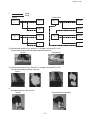
Dedicated R410A tools
a) Gauge manifold
b) Charge hose
c) Electronic scale for refrigerant charging
d) Torque wrench
e) Flare tool
f) Protrusion control copper pipe gauge
g ) Vacuum pump adapter
h) Gas leak detector
'09•KX-T-139
1. BEFORE BEGINNING INSTALLATION (Check that the models, power supply specifications, piping, wiring are correct.)
CAUTION
Please read this manual without fail before you set to installation work and carry it out according to this manual.
For the installation of an indoor unit, please refer to the installation manual of an indoor unit.
● For piping work, optional distribution parts (branching pipe set, header set) are necessary. Please refer to our catalog, etc.
● Never fail to install an earth leakage breaker. (Please use one tolerable to harmonic components)
● Operating the unit with the outlet pipe thermistor, the inlet pipe thermistor, the pressure sensor, etc. removed can result in a compressor burnout. Avoid operation
under such conditions in any circumstances.
●
●
ACCESSORY
Quantity
Usage location
Wiring
2
In operating the unit in the silent mode, insert it to the outdoor unit board's
CNG.
It is supplied with the unit. You can find
it taped inside the control box.
Instruction manual
1
When the installation work is completed,
give instructions to the customer and ask him/her to keep it.
Attached on the side panel below the
operation valve.
Name
COMBINATION PATTERNS
● The possible outdoor unit combinations and the number and the total capacity of indoor units that can be connected in a system are shown in the table below.
● Please always use indoor units designed exclusively for R410A. For connectable indoor unit model names, please check with our catalog, etc.
● It can be used in combination with the following indoor unit.
Indoor unit Remote controller Connection OK/NO
FD○△△KXE6 RC-E3(2 cores) OK
FD○A△△KXE4R, KXE4BR, KXE5R RC-E1R(3 cores) OK
FD○A△△KXE4, KXE4(A), KXE4A RC-E1(3 cores) NO
Notabilia
The same outdoor unit is used whether it is used alone or in combination with another unit.
● Model type differs on the unit with 560 capacity depending on whether the unit is used independently and with the combined capacity of 1065 or 1130, or with
the combined capacity of 1180.
(When the unit is used independently and with the combined capacity of 1065 or 1130, the model type is 560. When the unit is used with the combined capacity
of 1180, the model type is 560-K.)
● Please note that an installation involving a combination other than those listed below is not operable.(For example, you cannot operate 560 and 680 in
combination)
Capacity
400
450
504
560
615
680
735
800
850
900
960
1010
1065
1130
1180
1235
1300
1360
Outdoor unit
Combination patterns
Single
Single
Single
Single
Single
Single
Combination(400+335-K)
Combination(400+400)
Combination(400+450)
Combination(450+450)
Combination(450+504)
Combination(504+504)
Combination(504+560)
Combination(560+560)
Combination(615+560-K)
Combination(615+615)
Combination(615+680)
Combination(680+680)
Indoor unit
Range of the total capacity of indoor units connected in a system※
200∼800
225∼900
252∼806
280∼896
308∼984
340∼1088
368∼1176
400∼1280
425∼1360
450∼1440
477∼1526
504∼1311
532∼1384
560∼1456
588∼1528
615∼1599
650∼1690
680∼1768
Number of connectable units (units)
1∼36
1∼40
1∼36
1∼40
2∼44
2∼49
2∼53
2∼58
2∼61
2∼65
2∼69
2∼59
2∼62
2∼66
3∼69
3∼72
3∼76
3∼80
【Optional parts】
Refrigerant distribution piping components supplied as optional parts will become necessary in installing the unit.
As refrigerant distribution piping components, branching pipe sets (model type: DOS) for the outdoor unit side piping, branching pipe sets (model type: DIS) and
header sets (model type: HEAD) for the outdoor unit side piping are available.
Select according to the application. Please refer to "4. Refrigerant piping work" in selecting.
If you are uncertain, please do not hesitate to consult with your distributor or the manufacturer.
Please use refrigerant branching sets and header sets designed exclusively for R410A without fail.
※ When connecting the indoor unit type FDK, FDFL or FDFU series, limit the connectable capacity not higher than130%.
Outdoor unit
Branching pipe set
on the indoor unit side
Model type: DIS
Outdoor unit
C
D
Branching pipe set
on the indoor unit side
Model type: DIS
A
A
Header set on the indoor unit side
Model type: HEAD
C
D
D
D
Indoor unit
C
A
B
C
D
Branching pipe set
on the outdoor unit side
Model type: DOS
-
Figure 1
29 -
D
D
D
Indoor unit
'09•KX-T-139
2. INSTALLATION LOCATION
(Obtain approval from the customer when selecting the installation area.)
2-1. Selecting the installation location
〇 Where air is not trapped.
〇 Where the installation fittings can be firmly installed.
〇 Where wind does not hinder the intake and outlet pipes.
〇 Out of the heat range of other heat sources.
〇 Where strong winds will not blow against the outlet pipe.
〇 A place where stringent regulation of electric noises is applicable.
〇 Where it is safe for the drain water to be discharged.
〇 Where noise and hot air will not bother neighboring residents.
〇 Where snow will not accumulate.
〇 A place where no TV set or radio receiver is placed within 5m.
(If electrical interference is caused, seek a place less likely to cause the problem)
Please note
a) A four-sided enclosure cannot be used. Leave a space of at least 1m above the unit.
b) If there is a danger of a short-circuit, then install a wind direction variable adapter.
c) When installing multiple units, provide sufficient intake space so that a short-circuit does not occur.
d) In areas where there is snowfall, install the unit in a frame or under a snow hood to prevent snow from accumulating on it.
(Inhibition of collective drain discharge in a snowy country)
e) Do not install the equipment in areas where there is a danger for potential explosive atmosphere.
* Please ask your distributor about optional parts such as wind vane adapters, snow guard hoods, etc.
CAUTION
Please leave sufficient clearance around
the unit without fail. Otherwise, a risk of
compressor and/or electric component
failure may arise.
2-2. Installation space (service space) example
Example installation
L1
L1
L2
L3
L4
H1
H2
H3
H4
Wall height H4
Wall height H2
L3
Dimensions
L4
(Front side of the unit)
Wall height H1
Ⅰ
Ⅱ
Ⅲ
500
10
100
10
1500
No limit
1000
No limit
500
50
50
50
1500
No limit
1000
No limit
Open
10
100
Open
Open
No limit
No limit
Open
Example installation
L4
L1
L2
L3
L4
L5
L6
H1
H2
H3
H4
L1
Wall height H2
Ⅰ
Ⅱ
500
10
100
10
10 (0)
10 (0)
1500
No limit
1000
No limit
Open
200
300
Open
400
400
Open
No limit
No limit
Open
Dimensions
L3
For a normal installation, leave a 10 ②When more than one unit are installed
mm or wider space on both sides of
Wall height H3
the unit (L5 and L6) as workspace.
It is also possible to install at a 0mm
interval (continuous installation) with
future renewal, etc. in mind.
L5
L6
For your information:
L2
the footprint of an outdoor unit is
1350x720 for all models throughout
(Front side of the unit)
the series (335–K–680).
Wall height H4
Please secure sufficient clearance ①When one unit is installed
(room for maintenance work,
Wall height H3
passage, draft and piping). (If your
installation site does not fulfill the
installation condition requirements
set out on this drawing, please
consult with your distributor or the
L2
manufacturer)
Wall height H1
3. Unit delivery and installation
CAUTION
When a unit is hoisted with slings for haulage, please take into consideration the offset of its gravity center position.
If not properly balanced, the unit can be thrown off-balance and fall.
3-1. Delivery
●
●
By defining a cartage path, carry in the entire package containing a unit to its installation point.
In slinging a unit, use two canvas belts with plates, cloth pads or other protections applied to the unit to prevent damage.
Please note
a) Please do not fail to put belts through the rectangular holes of a unit's anchoring legs.
b) Apply cloth pads between a canvas belt and a unit to prevent damage.
3-2. Notabilia for installation
Anchor bolt positions
(● mark)
764
726
85
85
594
1350
850
720
Unit
20
(1) Anchor bolt positions
● Use four anchor bolts (M10) to fix an outdoor unit's anchoring legs at all times.
Ideally, an anchor bolt should protrude 20mm.
Ove
100mr
m
Base
Normally, it is desirable that a
base as specified in the drawing
above is provided.
A base used for a former model
is wrongly oriented and not
acceptable.
(2) Base
● Please install a unit after ascertaining that the bases have been made to sufficient strength and level to ensure the unit against
vibration or noise generation.
● Please construct a base to the size of a shadowed area (the entire bottom area of an outdoor unit's anchoring leg) shown on the
above drawing or larger.
● Please orient a base in the traversal direction (direction of W1350mm) of an outdoor unit as illustrated in the drawing above.
(3) Vibration isolating rubber
● A vibration isolating rubber must support an outdoor unit's anchoring leg by its entire bottom area.
Unit leg
Please note
1) Install a vibration isolating rubber in such a manner that the entire bottom area of an outdoor unit’s anchoring leg will rest on it.
2) Do not install an outdoor unit in such a manner that a part of the bottom area of its anchoring leg is off a vibration isolating rubber.
-
30 -
85
Please use it for renewal installation.
(Please add a base on the center)
It is necessary to prevent sagging.
Vibration
isolating rubber
'09•KX-T-139
4. REFRIGERANT PIPING
4-1. Restrictions on the use of pipes
(1) Limitation on use of pipes
In installing pipes, always observe the restrictions on the use of pipes specified in this Section (1) including Maximum length, Total pipe
length, Allowable pipe length from the first branching, and Allowable elevation difference (head difference).
●
Please avoid forming any trap (
) or bump (
) in piping as they can cause fluid stagnation.
Maximum length (from an outdoor unit to the farthest indoor unit) ・・・・・・・・・ 160 m or less as actual pipe length (185 m or less as equivalent pipe length)
(When an actual pipe length exceeds 90m, however, it is necessary to change the gas pipe size. Please determine the main pipe size by consulting with the Main
Selection Reference Table set out in Section (3) (b).
● Total pipe length ・
・・・・・・・
・
・
・
・
・
・
・
・
・
・
・
・
・
・
・
・
・
・
・
・
・
・
・
・
・
・
・
・
・
・
・
・
・
・
・
・
・
・
・
・
・
・
・
・
・
・
・
・
・
・
・
・
・ 1000 m or less
CAUTION
● Main pipe length ・
・・・・・・・・・・・・・・・・・・・・・・・・・・・・・・・・・・・・・・・・・・・・・・・・・
・
・
・
・
・
・
・
・
・
・
・ 130 m or less
An installation not conforming to these restrictions can
● Allowable pipe length from the first branching ・
・・・・・・・・・・・・・・・・・
・
・
・
・
・
・
・
・
・
・
・ 90 m or less
induce a compressor failure, which shall be excluded from
the scope of warranty. Always observe the restrictions on
(However, difference between the longest and shortest piping ・・・・・・・・・・・・ 40 m or less)
the use of pipes in developing a system.
● Allowable elevation difference (head difference)
(a)When an outdoor unit is installed above ・・・・・・・・・・・・・・・・・・・・・・・・・・・・・・・・ 50~100 m
(b)Difference in the elevation of indoor units in a system ・・・・・・・・・・・・・・・・・ 18 m or less
(c)Elevation difference between the first branching point and the
Height difference between
Outdoor unit
outdoor units 0.4m
indoor unit ・・・・・・・・・・・・・・・・・・・・・・・・・・・・・・・・・・・・・・・・・・・・・・・・・・・・・・・・・・・・・・・ 18 m or less
● Restrictions on piping applicable to the section between an
Distance between an outdoor
outdoor unit andan outdoor unit side branching pipe (combination unit)
unit and an outdoor unit side
(a)Difference in the elevation ・・・・・・・・・・・・・・・・・・・・・・・・・・・・・・・・・・・・・・・・・・・・・・・ 0.4 m or less
branching pipe 5m
Outdoor unit
(b)Distance between an outdoor unit and an outdoor unit side branching pipe ・・・ 5 m or less
(c)Length of oil equalization piping ・・・・・・・・・・・・・・・・・・・・・・・・・・・・・・・・・・・・・・・・ 10 m or less
●
●
Height difference between
indoor units 18m
Important
When the Additional refrigerant quantity (P+I) is over the
following table, please separate the refrigerant line.
Outdoor unit
P+I (kg)
400-680
735-1360
50
100
Difference in the elevation 50~100m
Actual length 160m
Equivalent length 185m
Total length 1000m
Indoor unit
(2) Piping material selection
Please use pipes clean on both the inside and outside and free from contaminants harmful to operation such as sulfur, oxides, dust, chips, oil, fat and water.
Use the following material for refrigerant piping.
Material: phosphorus deoxidized seamless copper pipe (C1120T-0, 1/2H, JIS H3300)
Use C1220T-1/2H for φ19.05 or larger, or C1220T-0 for φ15.88 or smaller
● Do not use φ28.58 x t1.0, φ31.8 x t1.1, φ34.92 x t1.2 and φ38.1 x t1.35 as a bent pipe.
● Thickness and size: Please select proper pipes according to the pipe size selection guideline.
(Since this unit uses R410A, always use 1/2H pipes of a specified minimum thickness or thicker for all pipes of φ19.05 or larger, because the pressure
resistance requirement is not satisfied with O-type pipes).
● For branching pipes, use a genuine branching pipe set or header set at all times. (optional parts)
● For the handling of operation valves, please refer to P.8 4-3(3) Method of operating operation valves.
● In installing pipes, observe the restrictions on the use of pipes set out in Section 1 (Maximum length, total pipe length, allowable pipe length from the first
branching, allowable elevation difference (head difference)) without fail.
● Install a branching pipe set, paying attention to the direction of attachment, after you have perused through the installation manual supplied with it.
●
●
(3) Pipe size selection
(a) Outdoor unit – Outdoor unit side branching pipe: Section A in Figure 1
Please use a pipe conforming to the pipe size specified for outdoor unit connection.
Indoor unit connecting pipe size table
Outdoor unit
Outdoor unit outlet pipe specifications
Gas pipe
Connection method
Liquid pipe
Connection method Oil equalizing tube Connection method
φ25.4 (φ28.58) ×t1.0
335-K,400
450
504
φ9.52×t0.8
φ12.7×t0.8
Flare
Flare
Blazed
φ28.58×t1.0
560
※1
615
680
Pipe sizes applicable to European installations are shown in parentheses.
Please use C1220T-1/2H for φ19.05 or larger pipes.
※1: Please connect the master and slave units with an oil equalization pipe, when they are used in a combined installation.
(It is not required, when a unit is used as a standalone installation)
-
31 -
'09•KX-T-139
(b) Main (Outdoor unit side branching pipe – Indoor unit side first branching pipe): Section B in Figure 1
If the longest distance (measured between the outdoor unit and the farthest indoor unit) is 90m or longer (actual length), please change the main gas pipe size
according to the table below.
Outdoor unit
400
450
504
560
615
680
735
800
850
900
960
1010
1065
1130
1180
1235
1300
1360
Main pipe size (normal)
Gas pipe
Liquid pipe
φ25.4 (φ28.58) × t 1.0
φ12.7× t 0.8
φ28.58×
t 1.0
φ31.8 × t 1.1
(φ34.92× t 1.2)
φ15.88×
t 1.0
φ19.05×
t 1.0
Pipe size for an actual length of 90m or longer
Gas pipe
Liquid pipe
φ28.58× t 1.0
φ12.7× t 0.8
φ31.8× t 1.1
(φ28.58× t 1.0)
φ15.88×
t 1.0
φ19.05×
t 1.0
φ22.22×
t 1.0
φ38.1× t 1.35
(φ34.92× t 1.2)
φ38.1× t 1.35
(φ34.92× t 1.2)
φ22.22×
t 1.0
Please use C1220T-1/2H for φ19.05 or larger pipes.
Pipe sizes applicable to European installations are shown in parentheses.
(c) Indoor unit side first branching pipe – Indoor unit side branching pipe: Section C in Figure 1
Please choose from the table below an appropriate pipe size as determined by the total capacity of indoor units connected downstream, provided, however, that the
pipe size for this section should not exceed the main size (Section B in Figure 1).
Total capacity of indoor units
Less than 70
70 or more but less than 180
180 or more but less than 371
371 or more but less than 540
540 or more but less than 700
700 or more but less than 1100
1100 or more
Gas pipe
t 1.0
φ15.88× t 1.0
φ19.05× t 1.0 *1
φ25.4× t 1.0
(φ28.58) φ28.58× t 1.0
φ31.8× t 1.1 (φ34.92× t 1.2)
φ38.1× t 1.35 (φ34.92× t 1.2)
φ12.7×
Liquid pipe
φ
9.52× t 0.8
φ12.7
× t 0.8
φ15.88×
t 1.0
φ19.05×
t 1.0
Please use C1220T-1/2H for φ19.05 or larger pipes.
Pipe sizes applicable to European installations are shown in parentheses.
*1: When connecting indoor units of 280 at the downstream and the main gas pipe is of ø22.22 or larger, use the pipe of ø22.22x t1.0.
(d) Indoor unit side branching pipe – Indoor unit: Section D in Figure 1
Indoor unit connection pipe size table
Capacity
Gas pipe
9.52× t 0.8
φ 12.7× t 0.8
φ15.88× t 1.0
φ19.05× t 1.0
φ22.22× t 1.0
Liquid pipe
φ
22, 28
36, 45, 56
Indoor unit
71, 80, 90, 112, 140, 160
224
280
Please use C1220T-1/2H for φ19.05 or larger pipes.
φ
6.35× t 0.8
φ
9.52× t 0.8
(4) Selection of an outdoor unit side branching pipe set
This branching pipe set will always become necessary when units are used in combination.
(When a unit is used as a standalone installation, it is not required)
Outdoor unit
For two units (for 735 – 1360)
Branching pipe set
DOS-2A-1
Please note
a) In connecting an outdoor unit, please use a pipe conforming to the pipe size specified for outdoor unit connection.
b) Choose a different-diameter pipe joint matching a main pipe size specified in the following section in installing pipes (= main pipes) on the outdoor unit side.
c) Always install branching joints (for both gas and liquid) in such a manner that they form either correct horizontal or vertical branch.
(5) Selection of an indoor unit side branching pipe set
(a) Method of selecting a branching pipe set
● As an appropriate branching pipe size varies with the connected capacity (total capacity connected
downstream), determine a size from the following table.
Please note In connecting an indoor unit with the indoor unit side branching pipe set, please use a pipe
●
Total capacity downstream
Branching pipe set
Less than 180
DIS-22-1
180 or more but less than 371
DIS-180-1
371 or more but less than 540
DIS-371-1
540 or more
DIS-540-2
conforming to the pipe size specified for indoor unit connection.
● Always install branching pipes (both gas and liquid pipe) either horizontally or vertically.
Vertical
Horizontal
Floor surface
Floor surface
-
32 -
Floor surface
Floor surface
'09•KX-T-139
(b) Header Method
● Depending on the number of units connected, connect plugged pipes (to be procured on the installer’s part) at a branching point (on the indoor unit connection side).
● For the size of a plugged pipe, please refer to the documentation for a header set (optional part).
Total capacity downstream
Header set model type
Number of branches
Less than 180
HEAD4-22-1
4 branches at the most
180 or more but less than 371
HEAD6-180-1
8 branches at the most
371 or more but less than 540
HEAD8-371-1
8 branches at the most
540 or more
HEAD8-540-2
8 branches at the most
Please note a) In connecting a header with an indoor unit, please use a pipe conforming to the pipe size specified for indoor unit connection.
b) In installing a header, always arrange a gas-side header to branch horizontally and a liquid-side header to branch downward.
c) Indoor units 224 and 280 can not be connected to the header.
Gas side
Horizontal
Floor surface
Floor surface
Floor surface
Floor surface
Floor surface
downward
branch
Liquid side
Floor surface
4-2. Pipe connection position and pipe direction
(1) Pipe connecting position and pipe outgoing direction
Although this drawing illustrates an installation involving a 450 or smaller capacity unit, an installation involving a 504 or a larger capacity unit should be arranged in
the same manner as long as pipe connection points and directions are concerned, except that the height of a unit is different.
Measurements in [ ] indicate those of a 504 or larger capacity unit.
797.8[1155.8]
Rear side
F
6
D (front) 104.9
6
86.1
95
166
44.7
C (rear)
172
C (right)
291.6
C (front)
169
211
259
1690[2048]
Terminal block
for power cable
connection
A
90
D (right)
86.5
20
80
B
166
175
Signal wire
terminal block
G
682
7-segment
inspection port
84
Drain pipe
D (left)
1350
126.2
720
220 180
550
180 214
Rear side
Explanatory marks
E
234
120
141
95
140.5
75
142.5
Dimensions of a refrigerant pipe
connection port (plan)
C
101
B
A
G
185
80.5
The positions of connections on a base
A: Opening for refrigerant gas pipe connection
B: Opening for refrigerant liquid pipe connection
C: Refrigerant pipe port (φ88 or φ100)
D: Power cable port (φ50)
E: Power cable port (oblong hole measuring 40x80)
F: Holes for hoisting slings
G: Opening for oil equalizing pipe connection
An oil equalizing pipe must be connected only when an outdoor unit is used in a
combined installation.
(When a unit is used as a standalone installation, do not connect it)
A pipe can be laid through the front, right, bottom or rear of a unit as illustrated on the above drawings.
In laying pipes on the installation site, cut off the casing’s half blank (φ88 or φ100) that covers a hole for pipe penetration with nippers.
● When there is a danger that a small animal enters from the pipe port, cover the port with appropriate blocking materials (to be arranged on the user’s part).
● Use an elbow (to be arranged on the user’s part) to connect control valves to the piping.
● In anchoring piping on the installation site, give 1.5m or a longer distance between an outdoor unit and an anchoring point where the piping is secured as
illustrated below. (A failure to observe this instruction may result in a pipe fracture depending on a method of isolating vibrations employed.)
●
●
Outdoor unit
Outdoor unit
Over 1.5m
-
33 -
Pipe fastening position
'09•KX-T-139
(2) Piping work
CAUTION
If you tighten it without using double spanners, you may deform
the operation valve, which can cause an inflow of nitrogen gas
into the outdoor unit.
Important
Please take care so that installed pipes may not touch components within a unit.
In laying pipes on the installation site, keep the operation valves shut all the time.
● Give sufficient protections (compressed and brazed or by an adhesive tape) to pipe ends so that any water or foreign matters may not enter the pipes.
● In bending a pipe, bend it to the largest possible radius (at least four times the pipe diameter). Do not bend a pipe repeatedly to correct its form.
● An outdoor unit’s liquid pipe and liquid refrigerant piping are to be flare connected. Flare a pipe after engaging a flare nut onto it. A flare size for R410A is
different from that for conventional R407C. Although we recommend the use of flaring tools developed specifically for R410A, conventional flaring tools can
also be used by adjusting the measurement of protrusion B with a protrusion control gauge.
● Tighten a flare joint securely with two spanners. Observe flare nut tightening torque specified in the table below.
●
●
Flared pipe end: A (mm)
Copper
pipe outer A 0
-0.4
diameter
B
A
Copper pipe protrusion for flaring: B (mm)
Copper
In the case of a rigid (clutch) type
pipe outer
With an R410A tool With a conventional tool
diameter
φ6.35
9.1
φ6.35
φ9.52
13.2
φ9.52
φ12.7
16.6
φ12.7
φ15.88
19.7
φ15.88
0∼0.5
0.7∼1.3
Tightening torque (N m)
Operation valve size Tightening torque Tightening angle Recommended length of tool handle
(mm)
(N・m)
(mm)
(° )
ø6.35 (1/4") 14∼18 45∼60 150
ø9.52 (3/8") 34∼42 30∼45 200
ø12.7 (1/2") 49∼61 30∼45 250
ø15.88(5/8") 68∼82 15∼20 300
ø19.05 (3/4") 100∼120 15∼20 450
Do not hold the valve cap area with a spanner.
Use a torque wrench. If a torque wrench is not available,
fasten the flare nut manually first and then tighten it
further, using the left table as a guide.
Do not apply any oil on a flare joint.
Pipes are to be blazed to connect an outdoor unit’s gas pipe with refrigerant piping or refrigerant piping with a branching pipe set.
● Blazing must be performed under a nitrogen gas flow. Without nitrogen gas, a large quantity of foreign matters (oxidized film) are created, causing a critical
failure from capillary tube or expansion valve clogging.
● Brazing of the operation valve and the pipes should be performed while cooling the valve body with a wet towel.
● Perform flushing. To flush the piping, charge nitrogen gas at about 0.02MPa with a pipe end closed with a hand. When pressure inside builds up to a sufficient
level, remove the hand to flush. (in flushing a pipe, close the other end of the pipe with a plug).
●
●
Operation procedure
① In laying pipes on the installation site, keep the operation valves shut all the time.
② Blazing must be performed under a nitrogen gas flow. Without nitrogen gas, a large quantity of foreign matters (oxidized film) are created, causing a
critical failure from capillary tube or expansion valve clogging.
Taping
Nitrogen
Plug the end of the pipe with tape, or other
material, and fill the pipe with nitrogen gas.
N2
Only use nitrogen gas (N2)
Brazing
③ Give sufficient protections (compressed and brazed or with an adhesive tape) so that water or foreign matters may not enter the piping.
Flatten
Brazing
Adhesive tape
④ Perform flushing. To flush the piping, charge nitrogen gas at about 0.02MPa with a pipe end closed with a hand. When pressure inside builds up to a
sufficient level, remove the hand to flush. (in flushing a pipe, close the other end of the pipe with a plug).
Primary side
Station valve
Secondary side
0.02MPa
Hand
Nitrogen
gas
Relief valve
⑤ In brazing an operation valve and a pipe, braze them with the valve main body cooled with a wet towel or the like.
PSB012D942H
-
34 -
'09•KX-T-139
4-3. Air tightness test and air purge
(1) Air tightness test
① Although an outdoor unit itself has been tested for air tightness at the factory, please check the connected pipes and indoor units for air tightness from the check
joint of the operation valve on the outdoor unit side. While conducting a test, keep the operation valve shut all the time.
② Since refrigerant piping is pressurized to the design pressure of a unit with nitrogen gas for testing air tightness, please connect instruments according the drawing below.
Under no circumstances should chlorine-based refrigerant, oxygen or any other combustible gas be used to pressurize a system
Keep the operation valve shut all the time. Do not open it under any circumstances.
Be sure to pressurize all of the liquid, gas and oil equalizing pipes.
CAUTION
③ In pressurizing the piping, do not apply the specified level of pressure all at once, but gradually raise pressure.
Applying excessive pressure can cause an
a) Raise the pressure to 0.5 MPa, and then stop. Leave it for five minutes or more to see if the pressure drops. inflow of nitrogen gas into an outdoor unit.
b) Then raise the pressure to 1.5 MPa, and stop. Leave it for five more minutes to see if the pressure drops.
c) Then raise the pressure to the specified level (4.15 MPa), and record the ambient temperature and the pressure.
d) If no pressure drop is observed with an installation pressurized to the specified level and left for about one day, it is acceptable. When the ambient temperature
changes 1℃, the pressure also changes approximately 0.01 MPa. The pressure, if changed, should be compensated for.
e) If a pressure drop is observed in checking e) and a) – d), a leak exists somewhere. Find a leak by applying bubble test liquid to welded parts and flare joints and
repair it. After repair, conduct an air-tightness test again.
④Always pull air from the pipes after the airtightness test.
Airtight (pressurized) piping
Operation valve
To indoor unit
Operation valve
Liquid pipe
Liquid pipe
Gas pipe
Gas pipe
Gauge manifold
Lo
Nitrogen
gas
Hi
Lo knob
Hi knob
Service point
(check joint)
Oil equalizing
tube
Outdoor unit 1
CAUTION
(2) Vacuuming
Oil equalizing
tube
Outdoor unit 2
Please also pull air from the oil equalizing pipe.
Please pull air from the check joints of the operation valves on both liquid and gas sides.
Please also pull air from the oil equalizing pipe. (Please pull air separately from the rest of the piping by using the oil equalizing valve check joint)
<Work flow>
When the system has
remaining moisture inside or a
leaky point, the vacuum gauge
indicator will rise.
Check the system for a leaky
point and then draw air to
create a vacuum again.
Airtighteness test completed
Please run the vacuum pump for at least one hour
after the vacuum gauge shows -101kPa or lower.
(-755mmHg or lower)
Vacuuming begins
CAUTION
Vacuuming completed
Confirm that the vacuum gauge indicator does not
rise after leaving the system for an hour or more.
Vacuum gauge check
Insufficient vacuuming may result in poor
performance falling short of the design
capacity, pipe clogging due to residue
moisture and/or a compressor failure.
(Fill oil)
Fill refrigerant
Pay attention to the following points in addition to the above for the R410A and compatible machines.
○To prevent a different oil from entering, please assign dedicated tools, etc. to each refrigerant type. Under no circumstances must a gauge manifold and a
charge hose in particular be shared with other refrigerant types (R22, R407C, etc.).
○Use a counterflow prevention adapter to prevent vacuum pump oil from entering the refrigerant system.
(4) Method of operating operation valves
Method of opening/closing a valve
○Remove the cap, turn the gas pipe side until it comes to the “Closed” position as indicated in the
drawing on the right.
○For the liquid side pipe and oil equalizing pipe side, turn with a hexagonal wrench until the shaft
stops. If excessive force is applied, the valve main body can be damaged. Always use a
dedicated special tool.
○Tighten the cap securely.
For tightening torque, refer to the table below.
Tightening torque N・m
Shaft
Cap
Cap nut
(valve main body)
(lid)
(check joint section)
For gas pipes
7 or less
30 or less
13
7.85
29.4
8.8
For liquid pipes
(MAX 15.7)
(MAX 39.2)
(MAX 14.7)
16.2
For oil equalizing
4.9
8.8
(MAX 14.7)
(MAX 24.5)
(MAX 11.8)
tube
For fastening torque of a flare nut, please refer to Section 4-2 (2) Piping work on site.
-
35 -
S
O
O
When the total pipe length is longer than 510 m, charge 1,000 cc of M-MA32R refrigeration machine
oil from the check joint of gas pipe operation valve after the vacuuming.
S
(3) Additional oil charge
Opened position
Closed position
For gas pipes
For cap nut
Cap
For oil equalizing tube
For liquid pipes
'09•KX-T-139
4-4. Additional refrigerant charge
Charge additional refrigerant in the liquid state.
Be sure to measure the quantity with a scale in adding refrigerant.
If you cannot charge all refrigerant with the outdoor unit lying idle, charge it with the unit running in the test run mode. (For the test run method, please refer to Section 8)
If operated for a long time with insufficient refrigerant the compressor will be damaged. (In particular, when adding refrigerant during operation, complete the job within 30min.)
This unit contains <400~680: 11.5 kg, 735~1360: 23.0 kg> of refrigerant.
Determine the amount of refrigerant to be charged additionally using the following formula and put down the amount of refrigerant added on the refrigerant charge
volume recording plate provided on the back the front panel.
●Adding additional refrigerant
Charge additional refrigerant according to the size and length of the liquid piping and unit capacity.
Determine additional charge volume by rounding to the nearest 0.1 kg.
Additional fill quantity (kg) = S+P+I
S: standard additional refrigerant quantity (kg)
Outdoor unit
400
450
504
560
615
680
S (kg)
1.3
3.1
4.8
5.9
7.1
8.4
Outdoor unit
735
800
850
900
960
1010
S (kg)
1.7
2.6
4.4
6.2
7.9
9.6
Outdoor unit
1065
1130
1180
1235
1300
1360
S (kg)
10.7
11.8
13.0
14.2
15.5
16.8
P: Additional refrigerant quantity for piping (kg)
P = L1×0.37
L2×0.26
L3×0.18
L4×0.12
L5×0.059
L6×0.022
L1:φ22.22 total length (m) L2:φ19.05 total length (m) L3:φ15.88 total length (m)
L4:φ12.7 total length (m) L5:φ9.52 total length (m) L6:φ6.35 total length (m)
Refrigerant liquid pipe size
Additional fill quantity (kg/m)
φ22.22
φ19.05
φ15.88
φ12.7
φ9.52
φ6.35
0.37
0.26
0.18
0.12
0.059
0.022
Remarks
I: Additional refrigerant quantity for indoor units (kg)
If the total indoor units capacity is larger than 1.3 times of outdoor unit capacity, then calculate the additional refrigerant quantity for indoor units.
<Example>
D = {(Total indoor units capacity) - (outdoor unit capacity) x 1.3}
When you connect FDC400 to FDT140×4 units:
I = D x 0.01
D = 140×4 - 400×1.3 = 40 (>0)
When D > 0, calculate I using the above equation;
I = 40×0.01 = 0.4 (kg)
When D ≦ 0, take it as I = 0.
Important
Outdoor unit
400-680
735-1360
When the Additional refrigerant quantity (P+I) is over the following
table, please separate the refrigerant line.
P+I (kg)
50
100
Pay attention to the following points in addition to the above for the R410A and compatible machines.
To prevent a different oil from entering, please assign dedicated tools, etc. to each refrigerant type. Under no circumstances must a gauge manifold and a charge
hose in particular be shared with other refrigerant types (R22, R407C, etc.).
● Refrigerant types are indicated by color at the top of the cylinder 5. (Pink for R410A). Always confirm this.
● Do not use a charge cylinder under any circumstances. There is a danger that the composition of the refrigerant will change when R410A is transferred to a cylinder.
● When charging refrigerant, use liquid refrigerant from a cylinder. If refrigerant is charged in a gas form, the composition may change considerably.
●
Please note
Put down on the refrigerant charge volume recording plate provided on the back of the front panel the amount of refrigerant calculated from the pipe length.
CAUTION
Be sure to record the refrigerant volume,
because the information is necessary to
perform the installation’s maintenance
service.
It is located in back of this front panel.
4-5. Heating and condensation prevention
①Dress refrigerant pipes (both gas and liquid pipes) for heat insulation and prevention of dew condensation.
Improper heat insulation/anti-dew dressing can result in a water leak or dripping causing damage to household effects, etc.
②Use a heat insulating material that can withstand 120℃ or a higher temperature. Poor heat insulating capacity can cause heat insulation problems or cable
deterioration.
a) The gas pipe can cause during a cooling operation dew condensation, which will become drain water causing a possible water-leak accident, or reach during a
heating operation as high a temperature as 60℃ to 110℃, posing a risk of burns, when touched accidentally. So, do not fail to dress it with a heat insulation
material.
b) Wrap indoor units’ flare joints with heat insulating parts (pipe cover) for heat insulation (both gas and liquid pipes).
c) Give heat insulation to both gas and liquid side pipes. Bundle a heat insulating material and a pipe tightly together so that no gaps may be left between them and
wrap them together with a connecting cable by a dressing tape.
d) Although this air conditioning unit has been tested under the JIS condensation test conditions, the dripping of water may occur when it is operated in a
high-humidity atmosphere (23℃ or a higher dew point temperature). In such a case, apply an additional heat insulation material of 10 to 20 mm thick to dress an
indoor unit body, piping and drain pipes.
When the ambient dew point temperature becomes 28℃ or higher, or the relative humidity becomes 80% or higher, add further 10 to 20 mm thick heat insulation
material.
-
36 -
'09•KX-T-139
Wires for connecting indoor
and outdoor units
Exterior tape
Band (accessory)
Pipe cover (accessory)
Gas piping
Liquid piping
insulation
5. Drainage
●
Where water drained from the outdoor unit may freeze, connect the drain pipe using optional drain elbow and drain grommet.
6. ELECTRICAL WIRING WORK
Electrical installation work must be performed by an electrical installation service provider qualified by a power provider of the country.
Electrical installation work must be executed according to the technical standards and other regulations applicable to electrical installations in the country.
Please install an earth leakage breaker without fail. The installation of an earth leakage breaker is compulsory in order to prevent electric shocks or fire accidents.
(Since this unit employs inverter control, please use an impulse withstanding type to prevent an earth leakage breaker’s false actuation.)
Please note
a) Use only copper wires.
Do not use any supply cord lighter than one specified in parentheses for each type below.
- braided cord (code designation 60245 IEC 51), if allowed in the relevant part 2;
- ordinary tough rubber sheathed cord (code designation 60245 IEC 53);
- flat twin tinsel cord (code designation 60227 IEC 41)
- ordinary polyvinyl chloride sheathed cord (code designation 60227 IEC 53).
Please do not use anything lighter than polychloroprene sheathed flexible cord (cord designation 60245 IEC57) for supply cords of parts of appliances for outdoor use.
b) Use separate power supplies for the indoor and outdoor units.
c) A grounding wire must be connected before connecting the power cable. Provide a grounding wire longer than the power cable.
d) The power supplies for indoor units in the same system should turn on and off simultaneously.
e) Ground the unit. Do not connect the grounding wire to a gas pipe, water pipe, lightning rod or telephone grounding wire.
If improperly grounded, an electric shock or malfunction may result.
Never connect the grounding wire to a gas pipe because if gas leaks, it could cause explosion or ignition.
f) The installation of an impulse withstanding type earth leakage breaker is necessary. A failure to install an earth leakage breaker can result in an accident such as an
electric shock or a fire. Do not turn on the power until the electrical work is completed. Be sure to turn off the power when servicing.
g) Please do not use a condensive capacitor for power factor improvement under any circumstances. (It does not improve power factor, while it can cause an abnormal
overheat accident)
h) For power supply cables, use conduits.
i ) Please do not lay electronic control cables (remote control and signaling wires) and other high current cables together outside the unit. Laying them together can
result in malfunctioning or a failure of the unit due to electric noises.
j ) Power cables and signaling wires must always be connected to the power cable terminal block and secured by cable fastening clamps provided in the unit.
k) Fasten cables so that they may not touch the piping, etc.
l ) When cables are connected, please make sure that all electrical components within the electrical component box are free of loose connector coupling or terminal
connection and then attach the cover securely. (Improper cover attachment can result in malfunctioning or a failure of the unit, if water penetrates into the box.)
m) Make sure to use circuit breakers (earth leakage breaker and circuit breaker) of proper capacity. Use of breakers of larger capacity could result in trouble on
components or fire accident.
n) Install isolator or disconnect switch on the power supply wiring in accordance with the local codes and regulations.
o) After maintenance, all wiring, wiring ties and the like, should be returned to their original state and wiring route, and the necessary clearance from all metal parts
should be secured.
6-1. Wiring system diagrams
(Example of combination)
Outdoor unit power supply: 3 phase 4wiring 380-415V
Distributed, separate power supply system
Earth leakage breaker
(Impulse withstanding type)
Circuit breaker
for cabling
Outdoor unit
Grounding
wire
A
A
B
A: Power cable (Main power cable) [4 cores]
B: Signal wire (Super Link wire) [2 cores]
C: Power cable (indoor unit power cable)
[2 cores]
D: Remote control cord
[2 cores (FD○△△KXE6 indoor unit),
3 cores (FD○A△△KXE4.5 indoor unit)]
B
C
Circuit breaker
for cabling
Earth leakage breaker
Indoor unit
D
R
R
R
R
R
R
Remote control unit
Indoor unit power supply: Single-phase 220-240V
CAUTION
If the earth leakage breaker is exclusively for ground fault protection, then you will need to install a circuit breaker for wiring work.
-
37 -
'09•KX-T-139
6-2. Method of connecting power cables
(1) Method of leading out cables
●
●
As shown on the drawing in Section 4-2 (1), cables can be laid through the front, right, left or bottom casing.
In wiring on the installation site, cut off a half-blank (φ50 or oblong hole measuring 40x80) covering a penetration of the casing with nippers.
(2) Notabilia in connecting power cables
Power cables must always be connected to the power cable terminal block and clamped outside the electrical component box.
In connecting to the power cable terminal block, use round solderless terminals.
Connect the ground wire before you connect the power cable. When you connect a grounding wire to a terminal block, use a grounding wire longer than the power cable so that it may
not be subject to tension.
● Do not turn on power until installation work is completed. Turn off power to the unit before you service the unit.
Tightening torque (N・m)
● Ensure that the unit is properly grounded.
● Always connect power cables to the power terminal block.
M4 Outdoor signal line terminal block
0.9~1.2
● To connect a cable to the power terminal block, use a round crimp contact terminal.
M5 Power cable terminal block, Earth wire 2.00~2.35
●
Use specified wires in wiring, and fasten them securely in such a manner that the terminal blocks
are not subject to external force.
● In fastening a screw of a terminal block, use a correct-size driver.
Fastening a screw of a terminal block with excessive force can break the screw.
● For the tightening torque of terminals, refer to the list shown at right.
● When electrical installation work is completed, make sure that all electrical components within the
electrical component box are free of loose connector coupling or terminal connection.
●
M6
Power cable terminal block
2.5~2.8
Wire
Round crimp contact terminal
(3) Outdoor unit power supply specifications : 3 phase 380-415V
Power
source
Model
335-K,400
450
504
560
615
Moulded-case circuit breaker (A)
Cable size for power
Wire length
source (mm2 )
(m)
Rated current
Switch capacity
22
92
75
100
22
92
75
22
92
22
3 phase
4 wire
380-415V
50Hz/
380V60Hz
680
Earth leakage breaker
Earth wire
Size (mm2 )
Screw type
75A100mA less than 0.1 sec
5.5
M5
100
75A100mA less than 0.1 sec
5.5
M5
75
100
75A100mA less than 0.1 sec
5.5
M5
92
75
100
75A100mA less than 0.1 sec
5.5
M5
22
92
75
100
75A100mA less than 0.1 sec
5.5
M5
22
92
75
100
75A100mA less than 0.1 sec
5.5
M5
Please note
a) The method of laying cables has been determined pursuant to the Japanese indoor wiring regulations (JEAC8001). (Please adapt it to the regulations in effect
in each country)
b) In the case of distributed, separate power supply system, the listed data represent those of an outdoor unit.
c) For details, please refer to the installation manual supplied with the indoor unit.
(4) Indoor unit power supply specifications : Single phase 220-240V
Combined total Cable size for
power source
capacity
(mm2 )
of indoor units
Wire length
(m)
Moulded-case circuit breaker
(For ground fault, overload and short circuit protection)
Less than 7A
2
21
20A 100mA less than 0.1 sec
Less than 11A
3.5
21
20A 100mA less than 0.1 sec
Less than 12A
5.5
33
20A 100mA less than 0.1 sec
Less than 16A
5.5
24
30A 100mA less than 0.1 sec
Less than 19A
5.5
20
40A 100mA less than 0.1 sec
Less than 22A
8
27
40A 100mA less than 0.1 sec
Less than 28A
8
21
50A 100mA less than 0.1 sec
Signal wire size
(mm2 )
2cores x 0.75-2.0 ※
※ Please use a shielded cable.
Please note
a) The method of laying cables has been determined pursuant to the Japanese indoor wiring regulations (JEAC8001). (Please adapt it to the regulations in effect
in each country)
b) Wire length in the table above is the value for when the indoor unit is connect to the power cable in series also the wire size and minimum length when the
power drop is less than 2% are shown. If the current exceeds the value in the table above, change the wire size according to the indoor wiring regulations.
(Please adapt it to the regulations in effect in each country)
c) For details, please refer to the installation manual supplied with the indoor unit.
d) Wires connected to indoor units are allowed up to 5.5 mm2. For 8 mm2 or more, use a dedicated pull box and branch to indoor units with 5.5 mm2 or less.
e) ③ terminal on the terminal block is specified to connect only an optional auxiliary heater (power supply for heater).
-
38 -
#
'09•KX-T-139
6-3. Method of connecting signaling wires
The communication protocol can be choosen from following two types. One of them is the conventional Superlink (hereinafter previous SL) and the other is the new SuperlinkⅡ
(hereinafter new SL) . These two communication protocols have the following advantages and restrictions, so please choose a desirable one meeting your installation conditions
such as connected indoor units and centralized controller. When signal cables are connected into a network involving outdoor units, indoor units or centralized control equipment
that do not support new SL, please select communications in the previous SL mode, even if the refrigerant system is separated from theirs.
Communication protocol
New communication protocol (new SL)
Conventional communication protocol (previous SL)
Outdoor unit setting (SW5-5)
No. of connectable indoor units
No. of connectable outdoor units in a network
Signal cable (total length)
ON
Max. 48
Max. 48
Up to 1000m
Signal cable (furthest length)
Connectable units to a network
Up to 1000m
OFF (Factory default)
Max. 128
Max. 32
Units not supporting new SL (FD○A△△KXE4.5 series)
Units supporting new SL (FD○△△KXE6 series)
Can be used together.
Up to 1,500 m for 0.75 mm2 shielding wire (MVVS)
Up to 1,000 m for 1.25 mm2 shielding wire (MVVS)
Up to 1000m
Units supporting new SL (FD○△△KXE6 series)
Note: For FDT224 and 280 models, calculate the number of units taking 1 indoor unit as 2 units for the sake of communication.
● Signal cables are for DC 5 V. Never connect wires for 220/240 V or 380/415 V. Protective fuse on the PCB will trip.
① Confirm that signal cables are prevented from applying 220/240 V or 380/415 V.
② Before turning the power on, check the resistance on the signal cable terminal block. If it is less than 100 , power supply cables may be connected to the signal cable terminal block.
Standard resistance value=46,000 (Number of FD○A△△ KXE4・5 Series units connected×5) + (Number of FD○△△ KXE6 Series units connected×9)
If the resistance value is less than 100 , disconnect the signal cables temporarily to divide to more than one network, to reduce the number of indoor units on the same
network, and check each network.
Indoor and outdoor units signal cables
Connect the signal cable between indoor and outdoor units and the signal cable between outdoor units belonging to the same refrigerant line to A1 and B1.
Connect the signal line between outdoor units on different refrigerant lines to A2 and B2.
● Please use a shielded cable for a signal line and connect a shielding earth at all the indoor units and outdoor units.
●
●
(2) When plural outdoor units are used
(1) When one outdoor unit is used.
Outdoor signal line
terminal block
A1
B1
A B
A B
A B
Outdoor unit
Outdoor unit
A1・B1
A1・B1
A1・B1
A2・B2
A2・B2
Indoor unit
A2・B2
Indoor unit
Refrigerant pipe
A B
A1
B1
Indoor unit
A B
A B
A B
A1
B1
A1・B1
Network connector
A B
○Indoor and outdoor signal lines do not have a polarity.
Any of the connections in the following illustration can be made.
A2・B2
Outdoor unit
Indoor unit
A B
Indoor signal line
terminal block
Outdoor unit
Signal line
(3) The signal lines can also be connected using the method shown below.
Outdoor unit
Outdoor unit
Important
Outdoor unit
Outdoor unit
Indoor unit
Indoor unit
Indoor unit
Indoor unit
Indoor unit
Indoor unit
○Loop wiring prohibited.
Outdoor unit
Outdoor unit
Outdoor unit
The signal lines cannot form a
loop, so the wirings shown as .......
in the diagram are prohibited.
Indoor unit
Indoor unit
Indoor unit
Indoor unit
Remote controller wiring specifications
(1) A standard remote controller wire is 0.3mm2 x 2 cores (FDC○△△KXE6 indoor unit), 0.3mm2 x 3 cores (FD○A△△KXE4.5 indoor unit). It can be
extended up to 600m. For a remote controller wire exceeding 100m, please upgrade wire size as specified in the table below.
Length (m)
100 to 200
To 300
To 400
To 600
Wire size
FD○△△KXE6 indoor unit
FD○A△△KXE4 indoor unit
0.5mm2 × 2 cores
0.5mm2 × 3 cores
2
0.75mm × 2 cores
0.75mm2 × 3 cores
1.25mm2 × 2 cores
1.25mm2 × 3 cores
2 mm2 × 2 cores
2 mm2 × 3 cores
-
39 -
#
'09•KX-T-139
(2) When the remote controller wire runs parallel to another power supply wire or when it is subject to outside noise, such as from a high-frequency device, use
shielded wire. (Be sure to ground only one end of the shielded wire.)
CAUTION
In addition to a possible wiring error between indoor and outdoor units, there are other possibilities of erroneous wiring as illustrated below.
① Wrong wiring between signaling wires and
remote controller wires.
② Connecting power cables to the signaling wire
terminal block.
For remote control
Terminal block
For power cables
Terminal block
For signal wires
Terminal block
Indoor unit
X Y Z
1 2 3
A B
For signal wires
Terminal block
Indoor unit
③ Wrong wiring of remote controller wires.
For remote control
Terminal block
Indoor unit
Red White Black
A B
X
Y
Red
power cable (220-240V) Signal wire
Signal wire
White
Black
Remote control wire
Z
Wrong wiring of remote controller wires X , Z .
It will result in a blown signal line fuse (CNK).
Error indication:E1
7. CONTROLLER SETTINGS
7-1. Unit address setting
This control system controls the controllers of more than one air conditioner's outdoor unit, indoor unit and remote control unit through communication control, using the microcomputers built in
the respective controllers. Address setting needs to be done for both outdoor and indoor units. Turn on power in the order of the outdoor units and then the indoor units.
Use 1 minute as the rule of thumb for an interval between them.
The communication protocol can be chosen from following two types. One of them is the conventional communication protocol (previous SL) and the other is the new communication protocol (new
SL). These two communication protocols have their own features and restrictions as shown by Table 6-3. Select them according the indoor units and the centralized control to be connected.
When signal cables are connected into a network involving outdoor units, indoor units or centralized control equipment that do not support new SL, please select communications in the previous SL
mode, even if the refrigerant system is separated from theirs.
When communication is established after setting addresses, check the communication protocol with the 7 segment display panel of the outdoor unit.
●Address
setting methods
The following address setting methods can be used. The procedure for automatic address setting is different from the conventional one.
Please use the automatic address setting function after reading this manual carefully.
previous SL
new SL
Automatic Manual Automatic Manual
Communication protocol
Address setting method
When plural refrigerant systems
are linked with signal lines
(e.g., to implement centralized
control)
Case 1 When signal lines linking plural refrigerant systems are provided between outdoor units.
(When the network connector is disconnected, refrigerant systems are separated each other)
OK※1
OK
×
OK
Case 2 When signal lines linking plural refrigerant systems are provided between indoor units.
×※2
OK
×
OK
OK
OK
OK
OK
When only one refrigerant system is involved (signal lines do not link plural refrigerant systems)
※1 Do not connect the signal line between outdoor units on the different refrigerant lines to A1 and B1. Do not connect the signal line between outdoor units on the same
refrigerant line to A2 and B2. This may interrupt proper address setting. (Case 3)
Do not connect the signal line between indoor unit and outdoor unit to A2 and B2. This may interrupt proper address setting. (Case 4)
※2 In Case 2, automatic address setting is not available. Set addresses manually.
Outdoor unit
Outdoor unit
Outdoor unit
Outdoor unit
A1・B1 A2・B2
A1・B1 A2・B2
A1・B1 A2・B2
A1・B1 A2・B2
Outdoor unit
Outdoor unit
Outdoor unit
A1・B1 A2・B2
A1・B1 A2・B2
A1・B1 A2・B2
A1・B1 A2・B2
Refrigerant pipe
Indoor unit
Indoor unit
Indoor unit
A B
A B
A B
A B
Indoor unit
A B
Indoor unit
Outdoor unit
A B
Indoor unit
A B
Indoor unit
A B
Indoor unit
Network connector
Signal line
CASE 1
CASE 2
Outdoor unit
Outdoor unit
Outdoor unit
A1・B1 A2・B2
A1・B1 A2・B2
A1・B1 A2・B2
Outdoor unit
Outdoor unit
Outdoor unit
A1・B1 A2・B2
A1・B1 A2・B2
A1・B1 A2・B2
A1・B1 A2・B2
Indoor unit
CASE 3
Incorrect cable connection
(Cables between outdoor units on the same refrigerant line are connected to A2/B2.)
Incorrect cable connection
(Cables between outdoor units on different refrigerant lines are connected to A1/B1.)
-
40 -
Indoor unit
A B
A B
A B
A B
Indoor unit
Indoor unit
A B
Indoor unit
Outdoor unit
A B
Indoor unit
A1・B1 A2・B2
A B
Indoor unit
A B
Indoor unit
Outdoor unit
CASE 4
Incorrect cable connection
(Cables between indoor and outdoor units are connected to A2/B2.)
'09•KX-T-139
●Address
No. setting
Set SW1 through 4 and SW5-2 provided on the PCB and SW1 & 2 provided on the outdoor unit PCB as shown in the drawings below.
SW2 (SW4)
SW1 (SW3)
For ten’s place
●Summary
of address setting methods (figures in [
By inserting a flat driver
(precision screw driver) into this
groove and turn the arrow to
point a desired number.
For one’s place
] should be used with previous SL)
Units supporting new SL
Indoor unit address setting
Indoor No. switch
Outdoor No. switch
Manual address setting
(previous SL/new SL)
0 1
7 8
Indoor No. switch (The hundred’s Place) [OFF : 0, ON : 1]
5 6
SW5-2
7 8
SW1, 2 (green) For setting outdoor No. (The ten’s and one’s)
4
Outdoor PCB
9
2 3
SW3, 4 (green) For setting outdoor No. (The ten’s and one’s)
0 1
2 3
Indoor PCB
9
5 6
For setting indoor No. (The ten’s and one’s)
4
SW1, 2 (blue)
Units NOT supporting new SL
Indoor unit address setting
Outdoor unit address setting
Indoor No. switch
Outdoor No. switch
Outdoor No. switch
Outdoor unit address setting
Outdoor No. switch
000∼127[47]
00∼31[47]
00∼31[47]
00∼47
00∼47
00∼47
000
49
49
49
49
49
000
49
00∼31
×
×
×
Automatic address setting for
single refrigerant system installation
(previous SL/new SL)
Automatic address setting for
multiple refrigerant systems installation
(with new SL only)
Do not set numbers other than those shown in the table, or an error may be generated. Note: When units supporting new SL are added to a network using previous SL such as one involving FD○A△△KXE4.5 series units, choose previous SL for the communication protocol and set addresses
manually.
Since the models FDT224 and 280 have 2 PCBs per unit, set different indoor unit No. and SW on each PCB.
● An outdoor unit No., which is used to identify which outdoor unit and indoor units are connected in a refrigerant system, is set on outdoor unit PCB and indoor unit PCB. Give the same outdoor unit
No. to all outdoor unit and indoor units connected in same refrigerant system.
● An indoor unit No. is used to identify individual indoor units. Assign a unique number that is not assigned to any other indoor units on the network.
Unless stated otherwise, the following procedures apply, when new SL is chosen for the communication protocol.
When previous SL is chosen, use figures shown in [ ] in carrying out these procedures.
Manual address setting
Generally applicable to new SL/previous SL, use figures in [ ] with previous SL.
① Outdoor unit address setting
Set as follows before you turn on power. Upon turning on power, the outdoor unit address is registered.
Set a unique number by avoiding the numbers assigned to other outdoor units on the network.
Set the Outdoor Unit No. switch to a number 00 - 31 [in the case of previous SL: 00 - 47].
● Similarly for the master unit used in a combined installation, set the Outdoor Unit No. switch to a number 00-31 [in the case of previous SL:00-47].
● Similarly for the slave unit used in a combined installation, set the Outdoor Unit No. switch to the same number with a master unit and then, set the dipswitch SW4-7 of the slave unit
to ON. (Set both master and slave units to the same outdoor unit number.)
Refrigerant system
A
B
C
Outdoor unit
SW1
SW2
SW4-7
Address on a network
Master
2
0
OFF
20
Slave
2
0
ON
21
Master
2
2
OFF
22
Slave
2
2
ON
23
Master
3
1
OFF
31
Slave
3
1
ON
00
CAUTION
A slave unit's address will be set to "the master
unit's address +1." When you set a master unit’s
address, take care not to assign an address
duplicating with one used in another system. You
cannot operate the installation with a duplicating
address assigned. (Error indication: E-31)
This table shows an examples of address settings. As illustrated with the refrigerant systems A and B in the above example, when successive numbers
are used in setting addresses, care must be taken so that an address assigned to the master unit of the refrigerant system B will not duplicate with
one assigned to the slave unit of the refrigerant system A.
② Indoor unit address setting
Set as follows before you turn on power. Upon turning on power, the indoor unit address is registered.
Set the Indoor Unit No. switch to a number 000 - 127 [in the case of previous SL: 00 - 47].
Set the Outdoor Unit No. switch to the outdoor unit No. of the associated outdoor unit within the range of 00 - 31 [in the case of previous SL: 00 - 47].
Set a unique number by avoiding the numbers assigned to other indoor units on the network.
③ Turn on power in order from the outdoor unit to indoor units. Give a one-minute or longer interval for them.
* When there are some units not supporting new SL connected in the network, set SW5-5 to ON to choose the previous SL communication mode.
In the case of previous SL, the maximum number of indoor units connectable in a network is 48.
Example of address setting (manual)
The same setting with the master unit’s address number
(In the network, “the setting +1” is assigned.)
Slave setting
Outdoor unit(Master)
SW4-7 OFF
Outdoor unit No.20
Indoor unit
Outdoor unit No.20
Indoor unit No.01
Outdoor unit(Slave)
SW4-7 ON
Outdoor unit No.20(21)
Indoor unit
Outdoor unit No.20
Indoor unit No.02
Outdoor unit(Master)
SW4-7 OFF
Outdoor unit No.22
Indoor unit
Outdoor unit No.20
Indoor unit No.03
Set an outdoor unit number in the system
Indoor unit
Outdoor unit No.22
Indoor unit No.04
Take care not to assign an address duplicating with
one used in another system.
(Use every second number in setting an address)
Outdoor unit(Slave)
SW4-7 ON
Outdoor unit No.22(23)
Indoor unit
Outdoor unit No.22
Indoor unit No.05
Indoor unit
Outdoor unit No.22
Indoor unit No.06
Take care not to assign a duplicating address in a network.
-
41 -
indicates signaling wires (A/B).
indicates refrigerant piping.
'09•KX-T-139
Automatic address setting
Generally applicable to new SL/previous SL, use figures in [ ] with previous SL.
With new SL, you can set indoor unit addresses automatically even for an installation involving multiple refrigerant systems connected with same network, in addition to the conventional automatic
address setting of a single refrigerant system installation.
However, an installation must satisfy some additional requirements such as for wiring methods, so please read this manual carefully before you carry out automatic address setting.
(1) In the case of a single refrigerant system installation (Generally applicable to new SL/previous SL, use figures in [ ] with previous SL.)
① Outdoor unit address setting
Set as follows before you turn on power.
Make sure that the Outdoor Unit No. switch is set to 49 (factory setting).
- Similarly for the master unit used in a combined installation, make sure that the Outdoor unit No. switch is set to 49 (factory setting).
- Similarly for the slave unit used in a combined installation, make sure that the Outdoor unit No. switch is set to 49 (factory setting).
Then, set the dipswitch SW4-7 of the slave unit to ON.
Outdoor unit
SW1
SW2
SW4-7
Address on a network
Master unit
Slave unit
4
4
9
9
OFF
49
00
ON
CAUTION
If the slave unit is not specified, a
compressor failure may result.
The master unit will be registered as “49” regardless of the SW1 and SW2 settings (49).
The slave unit will be registered as “00” because of its SW4-7 setting as indicated in the table above.
② Indoor unit address setting
Set as follows before you turn on power.
Make sure that the Indoor Unit No. switch is set to 000 [in the case of previous SL: 49] (factory setting).
Make sure that the Outdoor Unit No. switch is set to 49 (factory setting).
③ Turn on power in order from the outdoor unit to indoor units. Give a one-minute or longer interval for them. Unlike the procedure set out in (2) below, you need not change settings from the 7
segment display panel.
④ Make sure that the number of indoor units indicated on the 7 segment display panel agrees with the number of the indoor units that are actually connected to the refrigerant system.
(2) In the case of a multiple refrigerant systems installation (Applicable to new SL only. In the case of previous SL, set addresses with some other method.)
(This option is available when the interconnection wiring among refrigerant systems is on the outdoor side and new SL is chosen as the communication protocol.)
Address setting procedure (perform these steps for each outdoor unit)
[STEP1] (Items set before turning on power)
① Outdoor unit address setting
Set as follows before you turn on power.
Set the Outdoor Unit No. switch to a number 00 - 31. Set a unique number by avoiding the numbers assigned to other outdoor units on the network.
● Similarly for the master unit used in a combined installation, set the Outdoor Unit No. switch to a number 00-31.
● Similarly for the slave unit used in a combined installation, set the Outdoor Unit No. switch to the same number with a master unit and then, set the dipswitch SW4-7 of the slave
unit to ON. (Set both master and slave units on the same outdoor unit number.)
② Indoor unit address setting
Set as follows before you turn on power.
Make sure that the Indoor Unit No. switch is set to 000 (factory setting).
Make sure that the Outdoor Unit No. switch is set to 49 (factory setting).
③ Isolate the present refrigerant system from the network.
Disengage the network connectors (white 2P) of the outdoor units. (Turning on power without isolating each refrigerant system will result in erroneous address setting.)
[STEP2] (Power on and automatic address setting)
④ Turn on power to the outdoor unit
Turn on power in order from the outdoor unit to indoor units. Give a one-minute or longer interval for them.
⑤ Select and enter “1” in P31 on the 7 segment display panel of each outdoor unit (master unit in case of combination) to input “Automatic address start.”
⑥ Input a starting address and the number of connected indoor units.
Input a starting address in P32 on the 7 segment display panel of each outdoor unit (master unit in case of combination).
⑦ When a starting address is entered, the display indication will switch back to the “Number of Connected Indoor Units Input” screen.
Input the number of connected indoor units from the 7 segment display panel of each outdoor unit (master unit in case of combination). Please input the number of connected indoor units (on
the same refrigerant line in case of combination) for each outdoor unit. (You can input it from P33 on the 7 segment display panel.)When the number of connected indoor units is entered, the 7
segment display panel indication will switch to “AUX” and start flickering.
[STEP3] (Automatic address setting completion check)
⑧ Indoor unit address determination
When the indoor unit addresses are all set, the 7 segment display panel indication will switch to “AUE” and start flickering.
If an error is detected in this process, the display will show “A○○.”
Check the 7 segment display panel of each outdoor unit (master unit in case of combination).
Depending on the number of connected indoor units, it may take about 10 minutes before the indoor unit addresses are all set.
[STEP4] (Network definition setting)
⑨ Network connection
When you have confirmed an “AUE” indication on the display of each outdoor unit, engage the network connectors again.
⑩ Network polarity setting
After you have made sure that the network connectors are engaged in ⑧, select and enter “1” in P34 on the 7 segment display panel of any outdoor unit (on only 1 unit : master
unit in case of combination) to specify network polarity.
⑪ Network setting completion check
When the network is defined, “End” will appear on the 7 segment display panel. An “End” indication will go off, when some operation is made from the 7 segment display panel or
3 minutes after.
-
42 -
'09•KX-T-139
STEP1
STEP2
STEP3
STEP4
Indoor unit power source
②OFF
④ON
ー
ー
Outdoor unit power source
①OFF
④ON
ー
ー
Indoor unit
(indoor/outdoor No.SW)
②indoor000/outdoor 49
(factory setting)
ー
ー
Outdoor unit (outdoor No.SW)
①01,03(Ex)
ー
ー
ー
Network connectors
③Disconnect(each outdoor unit)
ー
⑤ Select “Automatic Address Start”
on each outdoor unit.
⑥outdoor 01:「01」(Ex)
outdoor 03:「04」(Ex)
⑦outdoor 01:「03」(Ex)
outdoor 03:「03」(Ex)
ー
⑨Connect(each outdoor unit)
ー
ー
ー
ー
ー
ー
⑩ Set in P34 on the 7 segment display
panel of any outdoor unit.
Start automatic address setting
Set starting address
Set the number of indoor unit
Polarity setting
⑦[AUX](Blink)
7 segment display
⑧ “AUE”(blink), or “A○○” in error events.
[STEP1]
ー
⑪「End」
[STEP2]
Outdoor unit
(Master) [01]
SW4-7 0FF
Outdoor unit
(Slave) [01 (02)]
SW4-7 ON
Outdoor unit
(Master) [03]
SW4-7 0FF
Outdoor unit
(Slave) [(03)(04)]
SW4-7 ON
Network connector
Outdoor unit
(Master) [01]
SW4-7 0FF
Outdoor unit
(Slave) [01 (02)]
SW4-7 ON
Start [01]
Number [03]
Outdoor unit
(Master) [03]
SW4-7 0FF
Start [04]
Number [03]
Refrigerant pipe
Indoor unit
(00)+01
Indoor unit
(00)+04
Indoor unit
Indoor unit
(01)+01
Indoor unit
(01)+04
Indoor unit
Indoor unit
(02)+01
Indoor unit
(02)+04
Indoor unit
Indoor unit
Indoor unit
Indoor unit
[STEP3]
Outdoor unit
(Slave) [(03)(04)]
SW4-7 ON
[STEP4]
Outdoor unit
(Master) [01]
SW4-7 0FF
Outdoor unit
(Slave) [01 (02)]
SW4-7 ON
Outdoor unit
(Master) [03]
SW4-7 0FF
Outdoor unit
(Slave) [(03)(04)]
SW4-7 ON
Outdoor unit
(Master) [01]
SW4-7 0FF
Outdoor unit
(Slave) [01 (02)]
SW4-7 ON
Outdoor unit
(Master) [03]
SW4-7 0FF
Indoor unit
01
Indoor unit
04
Indoor unit
01
Indoor unit
04
Indoor unit
02
Indoor unit
05
Indoor unit
02
Indoor unit
05
Indoor unit
03
Indoor unit
06
Indoor unit
03
Indoor unit
06
Outdoor unit
(Slave) [(03)(04)]
SW4-7 ON
・Within a refrigerant system, indoor units are assigned addresses in the order they are recognized by the outdoor unit. Therefore, they are not necessarily assigned addresses in
order from the nearest to the outdoor unit first as depicted in drawings above.
・Make sure that power has been turned on to all indoor units.
・When addresses are set, you can have the registered indoor unit address No.’s and the outdoor unit address No. displayed on the remote control unit by pressing its CHECK button.
・Automatic address setting can be used for an installation in which prulal indoor units are controlled from one remote control unit.
・Once they are registered, addresses are stored in microcomputers, even if power is turned off.
・If you want to change an address after automatic address setting, you can change it from the remote control unit with its “Address Change” function or by means of manual
setting. Set a unique address by avoiding the address assigned to other indoor unit on the network when the address is changed.
・Do not turn on power to centralized control equipment until automatic address setting is completed.
・When addresses are set, be sure to perform a test run and ensure that you can operate all indoor and outdoor units normally. Also check the addresses assigned to the indoor
units.
Address change (available only with new SL)
“Address Change” is used, when you want to change an indoor unit address assigned with the “Automatic Address Setting” function from a remote control unit.
Accordingly, the conditions that permit an address change from a remote control unit are as follows.
Indoor unit address setting
Outdoor unit address setting
Indoor No.SW
Outdoor No.SW
Automatic address setting forsingle refrigerant system installation
000
49
49
Automatic address setting for multiple refrigerant systems installation
000
49
00∼31
Outdoor No.SW
If “CHANGE ADD. ▼” is selected with some addresses falling outside these conditions, the following indication will appear for 3 seconds on the
remote controller ”INVALID OPER” .
-
43 -
'09•KX-T-139
Operating procedure
(1) When single indoor unit is connected to the remote controller.
Item
1
Address change mode
2
To set a new indoor unit No.
3
To set a new outdoor unit No.
Operation
Display
① Press the AIR CON No. switch for 3 seconds or longer.
[CHANGE ADD.▼]
② Each time when you press the
[CHANGE ADD.▼]
⇔[MASTER I/U▲]
switch, the display indication will be switched.
③ Press the SET switch when the display shows “CHANGE ADD. ▼”
and then start the address change mode, changing the display indication to the “Indoor Unit No.
Setting” screen from the currently assigned address.
[I/U 001 O/U 01] (1sec)
→[ SET I/U ADD.] (1sec)
→[I/U 001 ] (Blink)
④ Set a new indoor unit No. with the switch.
A number indicated on the display will increase or decrease by 1 upon pressing the ▲ or ▼
switch respectively.
[I/U 000▲」
⇔[I/U 001 ]
⇔[I/U 002 ]
⇔ ・・・
⇔[I/U 127▼]
⑤ After selecting an address, press the SET switch, and then the indoor unit address No. is defined.
[I/U 002] (2sec)
⑥ After showing the defined indoor address No. for 2 seconds, the display will change to the “Outdoor
Address No. Setting” screen.
The currently assigned address is shown as a default value.
[I/U 002] (2sec Lighting)
→[ SET O/U ADD.] (1sec)
→[O/U 01 ] (Blink)
⑦Set a new outdoor unit No. with the switch.
A number indicated on the display will increase or decrease by 1 upon pressing the ▲ or ▼
switch respectively.
[O/U 00▲]
⇔[O/U 01 ]
⇔[O/U 02 ]
⇔ ・・・
⇔[O/U 31▼]
⑧ After selecting an address, press the SET switch, and then the outdoor unit No. and the indoor
unit No. are defined.
[I/U 002 O/U 02] (2sec Lighting)
→[SET COMPLETE] (2sec Lighting)
→Returns to normal condition.
(2) When plural indoor units are connected to the remote controller.
When plural indoor units are connected, you can change their addresses without altering their cable connection.
Item
1
2
Address change mode
Selecting an indoor unit
to be changed address
3
Setting a new indoor unit No.
4
Setting a new outdoor unit No.
Operation
[CHANGE ADD▼]
② Each time when you press the
[CHANGE ADD▼]
⇔[MASTER I/U▲]
switch, the display indication will be switched.
③ Press the SET switch when the display shows “CHANGE ADD. ▼”
The lowest indoor unit No. among the indoor units connected to the remote control unit will be shown.
[ SELECT I/U] (1sec)
→[I/U 001 O/U 01▲] (Blink)
④ Pressing the switch will change the display indication cyclically to show the unit No.’s
of the indoor units connected to the remote controller and the unit No.’s of the outdoor units
connected with them.
[I/U 001 O/U 01▲」
⇔[I/U 002 O/U 01 ]
⇔[I/U 003 O/U 01 ]
⇔ ・・・
⇔[I/U 016 O/U 01▼」
⑤ Then the address No. of the indoor unit to be changed is determined and the screen switches to the
display “ SET I/U ADD.”
[ SET I/U ADD.] (1sec)
→[I/U 001 ](Blink)
⑥ Set a new indoor unit No. with the switch.
A number indicated on the display will increase or decrease by 1 upon pressing the ▲ or ▼ switch
respectively.
[I/U 000▲]
⇔[I/U 001 ]
⇔[I/U 002 ]
⇔ ・・・
⇔[I/U 127▼]
⑦ After selecting an address, press the SET switch. Then the address No.of the indoor unit is determined.
5
Ending the session
Display
① Press the AIR CON Unit No. switch for 3 seconds or longer.
[I/U 002] (2sec)
⑧ The display will indicate the determined indoor address No. for 2 seconds and then switch to the
“ SET O/U ADD.” screen.
A default value shown on the display is the current address.
[I/U 002] (2sec lighting)
⇔[ SET O/U ADD.](1sec)
⇔[O/U 01 ] (Blink)
⑨ Set a new outdoor unit No. with the switch.
A number indicated on the display will increase or decrease by 1 upon pressing the ▲ or ▼ switch
respectively.
[O/U 00▲]
⇔[O/U 01 ]
⇔[O/U 02 ]
⇔ ・・・
⇔[O/U 31▼]
⑩ After selecting an address, press the SET switch.
Then the address of the indoor unit and outdoor unit are determined.
[I/U 002 O/U 02](2sec lighting)
→[ SELECT](1sec lighting)
→[I/U SELECTION▼](lighting)
⑪ If you want to continue to change addresses, return to step ④.
[Press the switch](1sec)
→[SET COMPLETE] (2∼10sec
lighting)
⑫ If you want to end the session (and reflect new address settings)
In Step ⑩, press the ▼ switch to select “END ▲.”
If you have finished changing addresses, press the SET switch while “END ▲” is shown. While new
settings are being transmitted, “SET COMPLETE” will be indicated. Then the remote controller display will
change to the normal state.
[END▲]
→[SET COMPLETE] (2∼10sec lighting)
→Normal state
⑬ If you want to end the session (without reflecting new address settings)
Before you complete the present address setting session, press the “ON/OFF” switch.
Then the display is change to exit from this mode and switch the display to the normal state.
All address settings changed in the session will be aborted and not reflected.
[ON/OFF]
→Forced termination
The switch will continuously change the display indication to the next one in every 0.25 seconds when it is pressed for 0.75 seconds or longer.
If the Reset switch is pressed during an operation, the display indication returns to the one that was shown before the last Set switch operation.
Even if an indoor unit No. is changed in this mode, the registered indoor unit No. before address change mode is displayed when [I/U SELECTION ▼] is shown.
When “SET COMPLETE” is shown, indoor unit No.’s are registered.
NOTICE
Turn on power to centralized control equipment after the addresses are determined.
Turning on power in wrong order may result in a failure to recognize addresses.
-
44 -
'09•KX-T-139
●
7 segment display indication in automatic address setting
Items that are to be set by the customer
Code
Contents of a display
P30
Communication protocol 0: Previous SL mode
1: New SL mode
P31
Automatic address start
P32
Input starting address
P33
Input number of connected indoor units Specify the number of indoor units connected in the refrigerant system in automatic address setting.
P34
Polarity difinition (The communication plotocol is displayed ; display only)
Specify a starting indoor unit address in automatic address setting.
0: Network polarity not defined.
1: Network polarity defined.
7 segment display indication in automatic address setting.
Code
Contents of a display
AUX
During automatic address setting.
X: The number of indoor units recognized by the outdoor unit.
AUE
Indoor unit address setting is completed normally.
End
Polarity is defined. (Automatic address)
Completed normally.
Address setting failure indication
Code
Contents of a display
Please check
A00
Unable to find any indoor unit that can be actually communicated with.
Are signal lines connected properly without any loose connections?
Is power for indoor units all turned on?
A01
The number of the indoor units that can be actually communicated with is less
than the number specified in P33 on the 7 segment display panel.
Are signal lines connected properly without any loose connections?
Input the number of connected indoor units again.
A02
The number of the indoor units that can be actually communicated with is
more than the number specified in P33 on the 7 segment display panel.
Are signal lines connected properly without any loose connections?
Are the network connectors coupled properly?
Input the number of connected indoor units again.
A03
Starting address (P32) + Number of connected indoor units (P33) > 128
Input the starting address again.
Input the number of connected indoor units again.
A04
While some units are operating in the previous SL mode on the network, the
automatic address setting on multiple refrigerant systems is attempted.
Perform manual address setting.
Separate previous SL setting unit from the network
Arrange all units to operate in the new SL.
Error indication
Contents of a display
Code
Cause
・Incorrect manual address setting
E2
Duplicating indoor unit address.
E3
Incorrect pairing of indoor-outdoor units.
E11
Address setting for plural remote controllers.
・Indoor unit address is set from plural remote controllers.
E12
Incorrect adderess setting of indoor units.
・Automatic address setting and manual address setting are mixed.
E31
Duplicating outdoor unit address.
・Plural outdoor units are exist as same address in same network.
E46
Incorrect setting.
・Automatic address setting and manual address setting are mixed.
・An outdoor unit number that does not exist in the network is specified
・No master unit exists in combination outdoor unit.
-
45 -
'09•KX-T-139
7-2. Control mode switching
Controls of outdoor unit may be selected as follows using the dip switches on the PCB and C○○, P○○ on the 7-segment.
To change C○○, P○○ on the 7-segment, hold down SW8 (7-segement display increment up: 1-digit), SW9 (7-segment increment up: 10-digit) and SW7 (Data write/Enter).
Content of control
Control selecting method
Unit set※1
C○○, P○○ on 7-segment
SW setting on PCB
Master
SW3-2 to ON
ー
Automatic back up operation
Master
SW5-1 to ON + SW5-2 to ON
ー
Cooling test run
ー
Pump down operation
Close the fluid operation valve on outdoor unit and set as follows:
(1) SW5-2 on PCB to ON
(2) SW5-3 on PCB to ON
(3) SW5-1 on PCB to ON
SW4-5:OFF, SW4-6:OFF*2 80% (Factory default)
SW4-5:ON , SW4-6:OFF*2 60%
SW4-5:OFF, SW4-6:ON*2 40%
SW4-5:ON , SW4-6:ON*2 00%
Master
Master
Master
Set allocation of external
input function to “1” *2
SW5-5
Master/slave SW6-3 to ON
J13: Short-circuited (Factory default), J13: Open
Master
Master/slave J14: Short-circuited (Factory default), J14: Open
Master/slave J15: Short-circuited (Factory default), J15: Open
Inputting signals to external input terminals selects the demand mode.
(J13 short-circuited: Level input, J13 open: Pulse input)
ー
Communication method selection ON: Previous SL communication, OFF: New SL communication
ー
High static pressure mode
External input selection (CnS1, CnS2 only) Short-circuited: Level input, Open: Pulse input
ー
Defrosting mode is switched. (will enter defrosting mode more frequently)
ー
Defrost selection Short-circuited: Normal defrosting, Open: Forced defrosting
Operation priority selection
0: First push priority (at shipping)
1: Last push priority
Master
ー
C70
Master/slave
ー
C75
Outdoor unit fan snow protection control 0: Control disabled (at shipping)
1: Control enabled
ー
P11
Allocation of external input (CnS1)
ー
P12
Allocation of external input (CnS2)
ー
P13
Allocation of external input (CnG1)
ー
P14
Allocation of external input (CnG2)
ー
P16
Outdoor unit fan snow protection control ON time setting - 30 sec (at shipping) 10, 30-600 sec
Master/slave
※1 “Unit set” shown in the above table refers to the master/slave setting of units comprising a combined installation.
Master: control mode setting required for the master unit only (setting not required with the slave unit).
Master/slave: control mode setting required for both master and slave units.
※2 Control is switched when both the allocation of external input function (P11~14) and SW are changed.
By changing the allocation of external input functions (P11~14) on the 7-segment, functions of external
input terminals may be selected. Inputting signals to external input terminals enable the following functions.
Setting value for allocation of external input function
With external input terminals short-circuited With external input terminals open
"0" : External operation input
Invalid
Valid
"1" : Demand input
Invalid
Valid
"2" : Cooling/heating forced input
Valid
Invalid
"3" : Silent mode input
Valid
Invalid
"5" : Outdoor fan snow guard control input
Valid
Invalid
"6" : Test run external input 1 (equivalent to SW5-1)
Test run start
Normal
"7" : Test run external input 2 (equivalent to SW5-2)
Cooling
(Prohibited to use)
"8" : Silent mode 2
Valid
Invalid
"4" : Spare
"9" : Spare
7-3. External input and output terminals specifications
Name
Purpose (Factory default)
Specification
External input CnS1
External operation input (Short-circuited at shipping)
Non-voltage contactor (DC12V)
NICHIATSU B02B-XAMK-1 (LF) (SN)
External input CnS2
Demand input (Short-circuited at shipping)
Non-voltage contactor (DC12V)
NICHIATSU B02B-XARK-1 (LF) (SN)
External input CnG1
Forced cooling/heating made input (Open at shipping)
“*Short-circuit prohibited”
Non-voltage contactor (DC12V)
NICHIATSU B02B-XAEK-1 (LF) (SN)
External input CnG2
Silencing mode input (Open at shipping)
Non-voltage contactor (DC12V)
NICHIATSU B02B-XASK-1 (LF) (SN)
External output CnH
Operation output
DC12V output
MOLEX 5286-02A-BU
External output CnY
Error output
DC12V output
MOLEX 5266-02A
-
46 -
Operating side connector
'09•KX-T-139
7-4. Exclusive cooling setting of remote controller
This air-conditioner is an exclusive cooling unit. Set it for the exclusive cooling using the remote controller as follows.
(After this setting, the unit will not operate even if the heating operation is selected on the remote controller.)
Item
Function setting of wired
remote controller
Operation
Display
① Stop the air-conditioner. Then press the “SET” and “OPERATION SELECT” switches for 3 seconds or longer.
[FUNCTION SET ▼]
② Press the “SET” switch.
[
FUNCTION ▼] or [I/U FUNCTION ▼]
③ Select the “Remote control function ▼” by pressing the ▲ or ▼ switch.
[
FUNCTION ▼]
④ Press the “SET” switch.
[DATA LOADING] (Flashes for approx. 2 seconds.)
Then it changes to [GRILLE ↑↓SET] .
⑤ Press the ▲ or ▼ switch. (Function and number are displayed one after the other.)
Select the “MODEL TYPE”.
[MODEL TYPE]
⑥ Press the “SET” switch.
[HEAT PUMP] or [COOLING ONLY]
⑦ Select the “COOLING ONLY“ by pressing ▲ or ▼ switch.
[COOLING ONLY]
⑧ Press the “SET” switch.
[SET COMPLETE]
⑨ Press the “Operation/Stop” switch. Setting is completed.
・You can terminate the setting by pressing the “Operation/Stop” switch on the way of setting. Please note, however, that the setting becomes invalid unless the
setting is completed.
・If you press the “RESET” switch on the way of setting, the display returns to the last previous screen.
・For further details of other settings, refer to the section of function setting included in the installation manual of the remote controller.
8. TEST OPERATION AND TRANSFER
8-1. Before starting operation
(1) Make sure that a measurement between the power supply terminal block and ground, when measured with a 500V megger, is greater than 1 MΩ.
(2) Please check the resistance of the signaling wire terminal block before power is turned on. If a resistance measurement is 100Ω or less, it suggests a possibility
that power cables are connected to the signaling wire terminal block. (Please refer to 6-3. Standard resistance valve.)
(3) Be sure to turn on the crank case heater 6 hours before operation.
(4) Make sure that the bottom of the compressor casing is warm. (higher than outdoor temperature +5°C)
(5) Be sure to fully open the operation valves (liquid,gas and Equalizen oil piping (for a combined installation only)) for the outdoor unit.
Operating the outdoor unit with the valves closed may damage the compressor.
(6) Check that the power to all indoor units has been turned on. If not, water leakage may occur.
CAUTION
Please make sure that the operation valves (gas, liquid, oil equalizing pipe (for a combined installation only)) are full
open before a test run. Conducing a test run with any of them in a closed position can result in a compressor failure.
8-2. Check operation
It is recommended to practice the check operation in precedent to the test run.
[Even if the check operation is not practiced, the test run and normal operations can be performed.]
For further details regarding the check operation refer to page 52.
Important
・Practice the check operation after completing the address setting for the indoor and outdoor units and also after charging the refrigerant.
・To assure accurate checking, proper amount of refrigerant must be retained.
・Check operation cannot be done when the system is stopped by an error.
・Check operation cannot be done when the total capacity of connected indoor units is less than 80% of the outdoor unit capacity.
・Check operation cannot be done when the system communication method is previous SL.
・Don’t perform the check operation simultaneously on more than one refrigerant line. Accurate checking cannot be obtained.
・Practice the check operation within the operation temperature ranges (Outdoor temperature: 0 – 43°C, room temperature: 10 – 32°C). Check operation will not
start out of these ranges.
・Outdoor air processing unit cannot be checked. (It is possible to check indoor units other than the outdoor air processing unit of the same refrigerant line.)
(1) Check items
Check operation allows proving the following points.
・Whether or not the operation valve is left open (Operation valve open/close check). (In case of combination, however, all operation valves need to be closed on
master and slave units to obtain accurate judgment.)
・Whether or not the refrigerant pipes and signal cables are connected properly between indoor and outdoor units. (Mismatch check)
・Whether or not the indoor expansion valve operates properly. (Expansion valve failure check)
-
47 -
'09•KX-T-139
(2) Method of check operation
(a) Starting the check operation
・Confirm that all of the following switches are turned OFF: SW3-2 (Auto backup operation), SW3-6 (Pipe wash mode), SW3-7 (Forced cooling/heating mode),
SW5-1 (Test run), SW5-2 (Test run cooling setting), SW5-3 (Pump-down operation) and SW5-6, -7, -8 (Capacity measurement mode). (In case of combination, on
both main and slave units)
・At the next, turn the SW3-5 (Check operation) OFF ¡ON (only on master unit in case of combination) so that the check operation will start.
・ It takes 15 – 30 minutes normally (max. 80 min) from the start to the end of check operation.
(b) End the check operation and the result display
・When the check operation is over, the system stops automatically. The 7-segment indicator shows the result (only on master unit in case of combination).
<Normal ending>
・7-segment indicator shows “CHO End”.
・Return the SW3-5 to OFF. The 7-segment indicator returns to normal display.
・Return SW3-7 (Forced cooling/heating mode) to ON.
<Abnormal ending>
・7-segment indicator shows an error alarm.
・Referring to the section [Inspect here], repair the faulty section and return the SW3-5 to OFF.
・At the next, repeat the check operation from the Step (2) above.
Display on 7-segent indicator during check operation
Code indicato
Data indicator
Display contents
H1
Max. remaining time
Check operation preparation on. Indicates max. remaining time (min).
(In case of combination, indicated on master unit only.)
H2
Max. remaining time
Check operation on. Indicates max. remaining time (min).
(In case of combination, indicated on master unit only.)
Check operation on. (Including preparation operation on).
(Indicated only on slave unit of combination.)
HO
CHO
End
Normal ending of check operation.
(In case of combination, indicated on master unit only.)
Error display on 7-segment indicator after ending the check operation
Code indicato
Data indicator
Display contents
Check following points
Operation valve is closed.
(Refrigerant circuit is shut off
partially.)
CHL
・Isn’t the operation valve of outdoor unit left open?
・Is the low pressure sensor normal? (Detected pressure can be seen on
the 7-segment indicator.)
・Is the connector of indoor unit expansion valve coil connected?
・Isn’t the indoor unit expansion valve coil disconnected from the
expansion valve body?
・Is the indoor unit heat exchanger sensor normal? (Check if the sensor is
disconnected.)
CHU
Abnormal indoor unit No.
Mismatch between
・ Are the refrigerant pipes and signal cables connected properly between
refrigerant pipes and signal
the indoor and outdoor units?
cables. Refrigerant is not
・ Is the connector of indoor unit expansion valve coil connected?
circulated to the indoor unit of ・ Isn’t the indoor unit expansion valve coil disconnected from the
which No. is displayed.
expansion valve body?
・ Is the indoor unit heat exchanger sensor normal? (Check if the sensor is
disconnected.)
Abnormal indoor unit No.
Expansion valve on the indoor ・ Is the connector of indoor unit expansion valve coil connected?
unit of which No. is displayed ・ Isn’t the indoor unit expansion valve coil disconnected from the
is not operating properly.
expansion valve body?
・ Is the indoor unit heat exchanger sensor normal? (Check if the sensor is
disconnected.)
CHJ
CHE
CHE
Abnormal indoor unit No.
Abnormal ending of check
operation.
・ Isn’t any error displayed (E??) on the indoor unit or outdoor unit?
・ Are signal cables connected without play?
・ Hasn’t the SW setting been changed during the check operation?
Abnormal ending of check
operation. Indoor unit of which
No. is displayed is abnormal.
・ Isn’t any error displayed (E??) on the indoor unit or outdoor unit?
・ Are signal cables connected without play?
・ Is the power supply to the indoor unit turned on?
※ When any error is detected, errors other than those listed above may be displayed. In such occasion, refer to page 56.
-
48 -
'09•KX-T-139
8-3. Refrigerant quantity check
Refrigerant quantity check tells you whether the refrigerant quantity is excessive (over) or insufficient (low).
(Even if the check operation is not practiced, the test run and normal operation can be performed.)
For further details regarding the check operation refer to the technical data.
It must be noted that, during the check operation, the outdoor units and the indoor units are operated automatically.
Important
・Practice the refrigerant quantity check operation only after charging the measured quantity of additional
refrigerant.
・It is necessary to add or reduce the refrigerant depending on the result of refrigerant quantity check. Even when
it has been judged that proper quantity of refrigerant is retained, the result could become inadequate if the
operating conditions are changed.
・It should be noted, therefore, that a result under particular conditions cannot cover all operating conditions.
(1) Guideline of accuracy
Guidelines of judgment on the refrigerant quantity are as shown below.
It should be noted that the result of judgment could vary depending on the conditions of judgment.
Refrigerant quantity over
+10 kg (Single machine)
+20 kg (Combination machine)
Low refrigerant quantity
20% of the additional refrigerant quantity for piping (P)
(2) Confirmation before implementing the refrigerant quantity check
Confirm on all of the followings before starting the refrigerant quantity check.
・ Confirm that it has been completed all works up to “8-1 Before starting operation”.
・ Check operation cannot be done when the total capacity of connected indoor units is less than 80% of the outdoor unit capacity.
・ Check operation cannot be done when the system communication method is that of previous SL.
・ Check operation cannot be done when the system is stopped by an error.
・ Practice the check operation within applicable operation temperature range (Outdoor temperature: 10 - 43˚C, room temperature: 15 - 32˚C). Check operation
will not start out of these ranges.
・ Start the check operation only at 5 minutes after stopping all indoor units.
(3) Method of refrigerant quantity check operation
(a) Starting the refrigerant quantity check operation
・ Confirm that all of the following switches are turned OFF; SW3-2 (Auto backup operation), SW3-6 (Pipe wash mode), SW3-7 (Forced cooling/heating mode),
SW5-1 (Test run), SW5-2 (Test run cooling setting), SW5-3 (Pump-down operation) and SW5-6, 7, 8 (Capacity measurement mode). (In case of combination,
on both master/slave units)
・ At the next, turn the SW3-4 (Refrigerant quantity check operation) OFF → ON (only on master unit in case of combination) so that the check operation will start.
・ It takes 60 ~ 75 minutes normally from the start to the end of check operation.
(b) End of refrigerant quantity check operation and result display
・ When the check operation is over, the system stops automatically, and the result is displayed on the 7-segment indicator. (Only on master unit in case of
combination)
< Normal ending >
・ 7-segment indicator shows “Co End”.
・ Return the SW3-4 to OFF. 7-segment indicator returns to normal display.
・ Return SW3-7 (Forced cooling/heating mode) to ON.
< Abnormal ending >
・ 7-segment indicator shows an error alarm.
・ Repair the faulty section referring to the guidance, and return the SW3-4 to OFF.
・ At the next, repeat the check operation from the Step (2) above.
-
49 -
'09•KX-T-139
(4) After the refrigerant quantity check operation
Following codes may be displayed at the end of check operation, other than “Co End”.
Check and take action according to the contents of remedy. And then, repeat the check operation.
Display on 7-segment indicator after the check operation (Displayed on master unit only in case of combination.)
Code indicator
Data indicator
Co
Co
Co
Hi
Lo
H_L
Meaning
Refrigerant quantity over
Low refrigerant quantity
Remedy
① Too much refrigerant is charged. Reduce the quantity.
< Guidelines of reduction >
・Single machine:10 kg
・Combination machine:20 kg
Make sure to recover the refrigerant from the check joint of liquid pipe operation valve
using the refrigerant recovery device.
① Refrigerant quantity is insufficient. Recharge the refrigerant.
< Guideline of recharge>
・ 20% of the additional refrigerant quantity for piping* (Upper limit: 5 kg)
Recharge the refrigerant in the liquid state from the check joint of low pressure line.
Make sure to measure the quantity before recharging.
Couldn’t judge.
It cannot judge (a state that it cannot judge properly).
State of refrigerant might have been unstable during the check operation due to
influence of wind, temperature change, etc.
①Check the expansion valve of indoor unit (disconnected coil, disconnected connector
or faulty expansion valve).
② Implement at a later date by changing the conditions.
Check the following points.
① Haven’t you changed the setting of dip switches after the start? Return them to
original setting.
② Is any error code (E??) displayed? If Yes, refer to the troubleshooting section in the
technical data.
Co
---
Judgment was interrupted.
Co
HE
Starting conditions are not met.
Starting conditions are not met so that it cannot start the check operation.
Refer to “(2) Confirmation before implementing the refrigerant quantity check”.
※ “Additional refrigerant quantity for piping” means the value of “Additional refrigerant quantity for piping (P)” in the Section 4-4 Additional
refrigerant charge.
Other errors than above may also be displayed if errors are detected. In such occasion, inspect by referring to the separate technical data.
8-4. Test operation
(1) Test run from an outdoor unit.
Whether external inputs are set to ON or OFF, you can start a test run by using the SW5-1 and SW5-2 switches provided on the outdoor unit board.
Please set SW5-2 to ON for a cooling test run (It is set to OFF at the factory for shipment)
Turning SW5-1 from OFF to ON next will cause all connected indoor units to start.
When a test run is completed, please set SW5-1 to OFF.
Note: During a test run, an indoor unit cannot be operated from the remote control unit (to change settings). (“Under centralized control” is indicated)
(2) Method of starting a test run for a cooling operation from an outdoor unit: please operate a remote control unit according to the following steps.
(a) Start of a cooling test run
○Operate the unit by pressing the START/STOP button.
○Select the “COOLING” mode with the MODE button.
○Press the TEST RUN button for 3 seconds or longer.
The screen display will be switched from “Select with ITEM ▲
▼ ”→“Determine with SET ”→“Cooling test run▼.”
○When the SET button is pressed while “Cooling test run▼ ” is displayed, a cooling test run will start. The screen display will be switched to “COOLING TEST RUN.”
(b) Termination of a cooling test run
○When the START/STOP button or the “TEMP SET
” button is pressed, a cooling test run will be terminated.
Notes : for engineers undertaking piping or electrical installation work
When a test run is completed, please make sure again that the electrical component box cover and the main body panel have been attached before you turn
the unit over to the customer.
8-5. TRANSFER
○Use the instruction manual that came with the outdoor unit to explain the operation method to the customer.
Please ask the customer to keep this installation manual together with the operation manual of his indoor units.
○Instruct the customer that the power should not be turned off even if the unit is not to be used for a long time. This will enable operation of the air conditioner any time.
(Since the compressor bottom is warmed by the crank case heater, seasonal compressor trouble can be prevented.)
-
50 -
'09•KX-T-139
9. CAUTIONS FOR SERVICING (for R410A and compatible machines)
(1) To avoid mixing of different types of oil, use separate tools for each type of refrigerant.
(2) To avoid moisture from being absorbed by the ice machine oil, the time for when the refrigerant circuit is open should be kept as short as possible. (Within 10 min. is
ideal.)
(3) For other piping work, airtighteness testing, vacuuming, and refrigerant charging, refer to section 3, Refrigerant piping.
(4) Diagnostic Inspection Procedures
For the meanings of failure diagnosis messages, please refer to the nameplate provided on the unit (on the back of the controller lid)
(5) 7-segment LED indication
Data are indicated when so chosen with the indication selector switch. For the details of indication, please refer to the cable name plate attached on the unit. (On the
face of the controller lid)
(6) Internal wiring
After maintenance, all wiring, wiring ties and the like, should be returned to their original state and wiring route, and the necessary clearance from all metal parts
should be secured.
-
51 -
'09•KX-T-139
7
CHECK OPERATION PROCEDURE
(1) Check operation
The following ① – ③ can be checked automatically with this operation.
① Checking of operation valves opened/closed.
Checks to see if operation valves are opened.
② Checking of mismatch on wiring or piping.
Checks to see if refrigerant piping or signal wiring between indoor and outdoor units in the same refrigerant system are
connected properly.
③ Checking of indoor expansion valve operation.
Checks to see if indoor expansion valve operates properly.
* Check operation should be performed before initial test run after completion of installation.
When any corrective measure for nonconformity has been taken, perform the check operation again after repair.
Operational condition
Temperature range: Outdoor air temperature … 0 㨪 43℃, Indoor air temperature … 10 㨪 32℃.
Connecting capacity of indoor units: 80% or more of outdoor unit capacity.
Precautions
Check each outdoor unit system for single use or each refrigeration system for combination use.
Outdoor units in other refrigerant system shall not be operated.
After turning on power supply to outdoor unit and connected indoor units, start check operation with all connected indoor
units stopped.
In combination use, check the setting and the result displayed on the 7-segment display of master outdoor unit.
If the unit has been operating before check operation, wait for 5 minutes after stopping the unit operation before starting
check operation, in order to avoid misjudgment.
In combination use, judging operation valves opened or closed by check operation can be done as no good (NG), when
all of operation valves in liquid line, gas line and oil equalizing line of both master and slave outdoor units are closed.
However, in other cases than the above, judgment may not be done.
During check operation it is impossible to stop operation from remote controller. Accordingly, before starting check operation,
be sure to confirm that no one working near the indoor unit especially near the rotating part such as fan of indoor unit or
something is remaining near the fan of indoor unit.
Purpose
ޓThe purpose of this check operation is only to verify any overlooked items to be checked during the ordinary checking done
at the site after installation. Accordingly it has no function to substitute the ordinary checking to be done during or after installation
work and to restore automatically as a result of checking operation.
ޓTherefore be sure to conduct the checking in ordinary way after installation firstly, and then to perform this check operation.
We believe that this checking method could prevent from overlooking any items to be checked.
-
52 -
'09•KX-T-139
(2) Flow of the check operation
Check operation is performed as follows.
Start
Preliminary check Note (1)
Auto checking Note (2)
Judgment of checked result Note (3)
NG
OK
End
Note (1) For preliminary check method, refer to “(3) Confirmation before check operation”.
(2) For details of check operation, refer to “(4) Check operation procedure”.
(3) For measures to be taken in case of NG, refer to “(5) Measures to be taken after check operation”.
-
53 -
'09•KX-T-139
(3) Confirmation before check operation
・Confirm the installation has been completed properly by hearing, actual inspection or other method.
・This preliminary confirmation is indispensable to prevent troubles during or after check operation.
・Check operation can be performed only when the following conditions (1) – (8) are established.
・Check the following contents listed in the table with 7-segment display and MentePC.
(1)
Item
Preparation
Content
Supply power to outdoor and
indoor units.
Check method
Check result
No outdoor unit in other
refrigerant systems is operating.
All indoor units are stopped.
It has elapsed more than 5
minutes after the stopping.
(2)
Connecting capacity of Connecting capacity of indoor
Check capacities of outdoor and indoor units.
indoor units
units is 80% or more of outdoor
unit capacity.
(3)
Address setting
Addresses of outdoor unit
Check the number of connected units.
(in combination use, both of master
and slave outdoor units) and
indoor units have been set.
(4)
Temperature range
Outdoor air temperature is 0 – Check outdoor air temperature with 7-segment
43℃. Indoor air temperature is display and indoor air temperature with
10 – 32℃.
MentePC.
(5)
Others
System communicating method Check the model name of outdoor unit, indoor
is of new SL.
units, central control device, etc.
System is not in error stop
condition.
Check to see if any error code (E??) is
displayed on indoor or outdoor unit.
(6)
Outdoor unit operation
valve
Outdoor unit operation valve is Check visually.
opened. *1
(7)
Refrigerant amount
Proper amount of refrigerant is Check the additional charged amount of
charged.
refrigerant is written in the plate for specifying
refrigerant charging amount on the back of
outdoor service panel.
(8)
Number of connected
indoor units
It is same as the number of
Check with 7-segement display or MentePC.
connected indoor units installed.
*1 ・Be sure to open the operation valves in both liquid and gas lines of outdoor unit before starting check operation. In combination use,
open the operation valves not only in liquid and gas lines but also in oil equalizing line of both master and slave outdoor units.
・Operating with operation valves closed causes vacuum operation that results in a compressor fault.
・If the operation valves are “closed” before test run, be sure to verify whether the evacuation, air tightness test and additional refrigerant
charge have been completed by hearing to installation contractor, before opening the operation valves.
Otherwise, it may cause such trouble as mixing air (non-condensation gas and water) in, forgetting to charge additional refrigerant
at the site, or others.
-
54 -
'09•KX-T-139
(4) Check operation procedure
Flow
Preliminary
check
Work
Operation status
(Displayed on 7-segment)
Meaning of
7-segment display
Check in advance as per “(3)
Confirmation before check
operation”.
Remarks
Don’t operate any outdoors unit in
other refrigerant systems during
check operation.
Start of check Turn “Chek operation switch “H1 Max. remaining time” Remaining time: Max. This operation status is displayed
operation
(SW3-5)” on outdoor control
remaining time for check during preparation for check
operation.
PCB from OFF to ON.
operation
Depending on conditions, it may not
“H0 HE”
When “H0-HE” is
be displayed.
In combination use, turn
displayed for more then 10 In combination use, “H0---” is
“Chek operation switch
minutes, then check
displayed on the slave outdoor unit.
(SW3-5) on master control
operation is not started yet. *Be sure to start check operation
PCB from OFF to ON.
In such case refer to “(3)
when all indoor units are stopping.
confirmation before check
Implementing
auto checking
End of auto
checking,
judgment
result
“H2 Max. remaining time” Remaining time: Max.
In combination use, “H0---” is
remaining time for auto displayed on the slave outdoor unit.
checking.
Record the indication of “CHO End”
7-segment indicator on
outdoor unit.
“CHL---”
Result of check operation End the check operation.
is judged normal.
Operation valve may be Refer to “(5) Measures to be
closed.
taken after check operation”.
“CHU Anomalous indoor Refrigerant piping or
unit No.”
signal wiring between
indoor and outdoor units
may not be connected
correctly.
“CHJ Anomalous indoor Indoor expansion valve
unit No.”
may not be operating
properly.
“CHE---”
Check operation has not
ended properly.
All judgment results at
the end are displayed.
Other display
Check of
Check for anomalous condition
nonconforming as per “(5) Measures to be
item
taken after check operation”
When any display other than Refer to “(5) Measures to be
“CHO-End” is displayed
taken after check operation”.
after auto checking.
End of check
operation
Returns to normal display.
Turn off “Chek operation
run switch (SW3-5)” on
outdoor control PCB.
Notes (1) W
hen “HO-HE” is displayed for more than 10 minutes, or any displays other than “CHO-End” is displayed at the end of cheek
operation, turn SW3-5 to OFF and take necessary measures.
And then turn SW3-5 to ON again and perform the check operation.
(2) During check operation it is impossible to stop operation from remote controller. Accordingly, before starting check operation, be
sure to confirm that no one working near the indoor unit especially near the rotating part such as fan of indoor unit or something is
remaining near the fan of indoor unit.
When interrupting check operation, turu SW3-5 to OFF, Compressor stops and 7-segment display returns to normal display.
-
55 -
'09•KX-T-139
(5) Measures to be taken after check operation
When any display other than “CHO-End” is displayed after completing the judgment of check operation, the meanings of each display
are shown as follows.
After checking the contents of inspection and repairing nonconforming items, perform check operation again.
Code
display
Data
display
CHL
---
Meaning of display
Contents of Inspection
Refrigerant circuit is choked at certain Operation valve on outdoor unit may be left closed.
place.
Low pressure sensor may be anomalous.
Check the detected pressure displayed on 7-segment and compare it with the
value measured with gauge manifold.
Refrigerant piping or signal wiring may not be connected properly. *1 (See page
58.) Check with Mente PC, etc.
Indoor heat exchanger temperature thermistor may be anomalous or disconnected.
*2 (See page 58.)
Refrigerant may not be charged correctly.
Indoor unit expansion valve may not be operating properly.
Connector of indoor unit expansion valve coil may not be connected. *3 (See page
58.)
Indoor unit expansion valve coil may be disconnected from main body of expansion
valve. *4 (See page 58.)
Outdoor unit PCB may be defective.
CHU
Anomalous Refrigerant is not circulated in the Refrigerant piping or signal cables may not be connected properly between indoor
indoor unit indoor unit of indicated No.
and outdoor units. *1 (See page 58.) Check with Mente PC, etc.
No.
Indoor heat exchanger temperature thermistor may be anomalous or disconnected.
*2 (See page 58.)
Operation valve on outdoor unit may be left closed.
Check it especially when many indoor units No. are displayed in data display column of CHU.
it may be displayed by influence of liquid flooding due to the trouble on any other
indoor unit. If CHJ is displayed at the same time, check preferentially the indoor
unit displaying CHJ and after repairing, perform check operation again.
Refrigerant may not be charged correctly.
Indoor unit expansion valve may not be operating properly.
Connector of indoor unit expansion valve coil may not be connected. *3 (See page
58.)
Indoor unit expansion valve coil may be disconnected from main body of expansion
valve. *4 (See page 58.)
CHJ
Anomalous Expansion valve on the indoor unit Indoor heat exchanger temperature thermistor may be anomalous or disconnected.
indoor unit of indicated No. does not operate *2 (See page 58.)
No.
properly.
it may be displayed by influence of liquid flooding due to the trouble on any other
indoor unit.
Contamination may be trapped in expansion valve due to installation or transitional cause.
Indoor unit expansion valve may not be operating properly.
Connector of indoor unit expansion valve coil may not be connected. *3 (See page
58.)
Indoor unit expansion valve coil may be disconnected from main body of expansion
valve. *4 (See page 58.)
Refrigerant may not be charged correctly.
CH1
---
Indoor heat exchanger temperature Indoor heat exchanger temperature thermistor may be anomalous or disconnected.
anomaly.
*2 (See page 58.)
CH3
---
Unable to do indoor EEV trouble check. Unable to do indoor EEV trouble check because of unstable operation.
-
56 -
'09•KX-T-139
Code
display
Data
display
CHH
---
Meaning of display
Contents of Inspection
It may be liquid flooding.
Refrigerant piping or signal cables may not be connected properly between indoor
and outdoor units. *1 (See next page.)
Power switch may be turned off on some indoor units.
Check if power is supplied to all indoor units.
Indoor unit expansion valve may not be operating properly.
Connector of indoor unit expansion valve coil may not be connected. *3 (See next
page)
Indoor unit expansion valve coil may be disconnected from main body of expansion
valve. *4 (See next page.)
If no indoor unit indicates CHJ, check also indoor units which are not showing CHJ.
Refrigerant may not be charged correctly.
CHE
---
Anomalous stop of check operation.
Some error may happen on indoor or outdoor units.
Check if any error code “E??” is displayed on indoor or outdoor units.
There may be anomalous on signal wire connection.
Check if signal wire is connected firmly.
SW setting on outdoor PCB might have been changed.
Check if any SW setting has been changed during check operation.
CHE
Anomalous Anomalous stop of check operation.
indoor unit
No.
Indoor unit indicated its No. has
anomaly.
Some error may happen on indoor or outdoor units.
Check if any error code “E??” is displayed on indoor or outdoor units.
There may be anomalous on signal wire connection.
Check if signal wire is connected firmly.
Power switch may be turned off on some indoor units.
Check if power is supplied to indoor units.
E
40
High pressure anomaly.
Refrigerant circuit may be choked at a certain place. Refer to the technical manual
or the above.
E
42
Current cut.
Refrigerant circuit may be choked at a certain place. Refer to the technical manual
or the above.
It might have been started operation while bottom of compressor was still cold.
Perform check operation again after the bottom of compressor has been enough
warm.
E
49
Low pressure anomaly.
Refrigerant circuit may be choked at a certain place. Refer to the technical manual
or the above.
E
36-3
Liquid flooding anomaly.
It may be in the same condition as “CHH---”. Refer to the technical manual or the
above.
Note (1) W
hen an error code (E??) is displayed, press SW9 to display all indicalions other than the error code in series.
Press SW9 again to return to error display.
(2) When check operation has been suspended, the followings listed in below table are displayed depending on judgment at
the time of stoppage.
Code display
Data display
HL
---
Refrigerant circuit is choked at a certain place.
Contents of display
HL
LPL
Refrigerant circuit is choked at a certain place. (In combination use)
HU
Anomalous indoor unit No. Refrigerant is not circulated in the indoor unit of indicated No.
HJ
Anomalous indoor unit No. Expansion valve does not operate on the indoor unit of indicated No.
UU
Anomalous indoor unit No. Refrigerant is not circulated in the indoor unit of indicated No.
U
Anomalous indoor unit No. Refrigerant was not circulated in the indoor unit of indicated No. just after starting but it
has been confirmed that it is now circulated.
(3) If refrigerant circuit is choked at a certain place, it may be stopped with error code E40 (High pressure anomaly), E42
(Current cut) or E49 (Low pressure anomaly).
(4) When it has stopped with error code E36-3 (Liquid flooding anomaly), it may be in the same condition as “CHH---”.
(5) When it has stopped with error code E42 (Current cut), it might have been started operation while bottom of compressor
was still cold. Perform check operation again after the bottom of compressor has been enough warm.
-
57 -
'09•KX-T-139
*1
Piping
Wiring
・ Wrong wiring
・Normal
Outdoor unit
1
Outdoor unit
1
Indoor unit
1
Indoor unit
2
Outdoor unit
2
Indoor unit
2
Indoor unit
3
Outdoor unit
2
Indoor unit
4
Indoor unit
3
Indoor unit
4
*2 (If the connector comes off by a weak pull, it’s no good. If not come off, It’s OK)
The connector of indoor heat exchanger temperature thermistor.
Normal Disconnected
*3 (If the connector comes off by a weak pull, it’s no good. If not come off, It’s OK)
The connector of indoor expansion valve coil.
Normal Disconnected
*4
The indoor expansion valve coil itself.
Normal Disconnected from main body
-
Indoor unit
1
58 -
Indoor unit
Outdoor
unit
Project name
1
2
3
4
5
6
7
8
9
10
11
12
13
14
15
16
17
18
19
20
21
22
23
24
25
26
27
28
29
30
31
32
33
34
35
36
37
38
39
40
No.
FD
FD
FD
FD
FD
FD
FD
FD
FD
FD
FD
FD
FD
FD
FD
FD
FD
FD
FD
FD
FD
FD
FD
FD
FD
FD
FD
FD
FD
FD
FD
FD
FD
FD
FD
FD
FD
FD
FD
FD
Model
Fill necessary data in advance
Address
Fill necessary data in advance
Model
Address
Master FDC
Slave FDC
<Check Operation Data Sheet>
(6) Data sheet
Piping length
O/U-I/U
Location
Elevation difference
O/U-I/U
41
42
43
44
45
46
47
48
49
50
51
52
53
54
55
56
57
58
59
60
61
62
63
64
65
66
67
68
69
70
71
72
73
74
75
76
77
78
79
80
No.
FD
FD
FD
FD
FD
FD
FD
FD
FD
FD
FD
FD
FD
FD
FD
FD
FD
FD
FD
FD
FD
FD
FD
FD
FD
FD
FD
FD
FD
FD
FD
FD
FD
FD
FD
FD
FD
FD
FD
FD
Model
Address
Piping length
O/U-I/U
Date of installation
(d/m/y)
Superlink version
Superlink II
Name of installer
Superlink I*
* In case of Superlink I, the check operation cannot be implemented.
Elevation difference
O/U-I/U
① No anomaly allowed.
→ If anomaly occurred: Error code E-
(Comment/Measures to be taken/etc.)
③ Others
② 7-segment display at completion
(h/m/)
(h/m/)
(d/m/y)
【Judgment】
Checked items
Checked by
Date of checking
Weather
Outdoor air temperature
Start time of check operation
Completion time of check operation
Result
℃
'09•KX-T-139
-
59 -
OUTDOOR UNIT
2.1 Specifications
• Single use (Used also for combination)
- 60 -
'09•KX-T-139
PCB003Z587
#
• Combination use
- 61 -
'09•KX-T-139
PCB003Z587
#
2.2 Exterior dimensions
Models FDCH335CKXE6G-K, 400CKXE6G, 450CKXE6G
- 62 -
'09•KX-T-139
PCB003Z589
#
Models FDCH504CKXE6G, 560CKXE6G, 560CKXE6G-K, 615CKXE6G, 680CKXE6G
- 63 -
'09•KX-T-139
PCB003Z590
#
2.3 Electrical wiring
Models All model
- 64 -
'09•KX-T-139
PCB003Z588
#
VRF INVERTER MULTI-SYSTEM AIR CONDITIONERS
Air-Conditioning & Refrigeration Systems Headquarters
16-5, 2-chome, Kounan, Minato-ku, Tokyo, 108-8215, Japan
Fax : (03) 6716-5926
Because of our policy of continuous improvement, we reserve the right to make changes in all specifications without notice.
c Copyright MITSUBISHI HEAVY INDUSTRIES.LTD