1
USER’S MANUAL
ORIGINAL INSTRUCTIONS
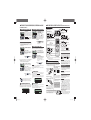
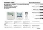
MITSUBISHI HEAVY INDUSTRIES LTD. PACKAGED AIR CONDITIONER
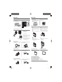
Ceiling cassette -4 way- (FDT)
Ceiling cassette -4 way Compact (600x600mm)- (FDTC)
Ceiling cassette -2 way- (FDTW)
Ceiling cassette -1 way Compact- (FDTQ)
Ceiling cassette -1 way- (FDTS)
Duct connected -High static pressure- (FDU)
Duct connected -Middle static pressure- (FDUM)
Ceiling suspended (FDE)
Wall mounted (FDK)
Floor standing -2 way- (FDFW)
Floor standing (with casing) (FDFL)
Floor standing (without casing) (FDFU)
Duct connected (Ultra thin) -Low static pressure- (FDQS)
Duct connected -Low static pressure- (FDUT)
Duct connected -Compact&Flexible- (FDUH)
Duct connected -High static pressure outdoor air processing unit (FDU -F)
USER’S MANUAL
ENGLISH
MANUEL DE L’UTILISATEUR
FRANÇAIS
ANWENDERHANDBUCH
DEUTSCH
ISTRUZIONI PER L’USO
ITALIANO
MANUAL DEL PROPIETARIO
ESPAÑOL
GEBRUIKERSHANDLEIDING
NEDERLANDS
MANUAL DO UTILIZADOR
PORTUGUÊS
О∆НГІЕΣ ХРНΣНΣ
ЕΛΛΗNIKA
РУССКИЙ
РУКОВОДСТВО ПО ЭКСПЛУАТАЦИИ U
TÜRKÇE
KULLANIM KILAVUZU
<WIRED REMOTE CONTROL>
RC-E5
<eco touch REMOTE CONTROL>
RC-EX series
<WIRELESS REMOTE CONTROL>
Please refer to the manual provided with eco touch REMOTE
CONTROL
Si prega di fare riferimento alla documentazione fornita con il
eco touch telecomando
Por favor, consulte a documentação que veio com o eco
touch controle remoto
S'il vous plaît se référer à la documentation fournie avec la
eco touch télécommande
Por favor, consulte la documentación que viene con el eco
touch mando a distancia
Ανατρέξτε στην τεκμηρίωση που συνόδευε το eco touch
τηλεχειριστήριο
Bitte beachten Sie die Dokumentation, die mit der eco touch
Fernbedienung kam
Raadpleeg de documentatie die bij de eco touch afstandsbediening
Пожалуйста, обратитесь к документации, поставляемой
с eco touch дистанционным управлением
eco touch uzaktan kumanda ile birlikte gelen belgelere bakın
This air conditioner complies with EMC Directive 2004/108/EC,
LV Directive 2006/95/EC.
CE marking is applicable to the area of 50 Hz power supply.
Dieses Kimagerät erfüllt die EMC Direktiven 2004/108/EC, LV
Direktiven 2006/95/EC.
Die CE-Marke gilt für Bereiche mit einer Netzstromversorgung
von 50 Hz.
Este acondicionador de aire cumple con la directiva EMC:
2004/108/EC, LV Directiva 2006/95/EC.
La indicación CE sólo corresponde al área de suministro
eléctrico de 50 Hz.
Este aparelho de ar condicionado está em conformidade com a
Directiva EMC 2004/108/EC, a Directiva LV 2006/95/EC.
A marca CE aplica-se à zona de fornecimento de energia a
50 Hz.
Ce climatiseur est conforme à la Directive EMC: 2004/108/EC,
LV Directive 2006/95/EC.
La marque CE s’applique aux régions alimentées en courant
de 50 Hz.
Questo condizionatore d’aria è conforme alla Direttiva EMC:
2004/108/EC, LV Direttiva 2006/95/EC.
Il marchio CE è applicabile alla fascia di alimentazione 50 Hz.
Deze airconditioner voldoet aan EMC Directive 2004/108/EC,
LV Directive 2006/95/EC.
CE-markering is van toepassing op het gebied met een netstroom van 50 Hz.
Το κλιματιστικό συμμορφώνεται προς την οδηγία 2004/108/ΕΚ
περί ηλεκτρομαγνητικής συμβατότητας (EMC) και την οδηγία LV
2006/95/ΕΚ.
Tο οήμα CE ισχύει μόνον σε περιοχές όπου η τροφοδοσία είναι
50 Hz.
PJZ012A087B
PJZ012A087B_cover.indd 1
B
2014-4-14 14:47:36
SAFETY PRECAUTIONS
Thank you very much for your purchase of this packaged air conditioning system
produced by Mitsubishi Heavy Industries. Please read through this manual before
using the product and use the product appropriately according to the instructions in
the manual. After you have read the manual, store it with the warranty certificate in a
safe place. It will help you when you have questions or problems.
Do not vent R410A into the atmosphere: R410A is a fluorinated greenhouse gas,
covered by the Kyoto Protocol with a Global Warming Potential (GWP) = 1975.
The emission sound pressure level from each Indoor and Outdoor unit is under
70 dB(A).
TABLE OF CONTENTS
J SAFETY
PRECAUTIONS ...................................................................................................................................................1
J HOW TO
USE
< WIRED REMOTE CONTROL >
NAMES AND FUNCTIONS OF REMOTE CONTROL BUTTONS
“WIRED REMOTE CONTROL” ...........................................................................................................................................4
HOW TO OPERATE ............................................................................................................................................................5
HOW TO PERFORM THE TIMER OPERATION .................................................................................................................5
THE SELECTION OF TIMER MODE ...............................................................................................................................5
SETTING THE TIME.........................................................................................................................................................6
SLEEP TIMER MODE ......................................................................................................................................................6
OFF TIMER MODE...........................................................................................................................................................6
ON TIMER MODE ............................................................................................................................................................7
WEEKLY TIMER MODE ...................................................................................................................................................7
TIMER CANCELLATION MODE ....................................................................................................................................10
HOW TO OPERATE IN SILENT MODE ............................................................................................................................10
HOW TO ADJUST THE LOUVER .....................................................................................................................................11
HOW TO SET THE AIRFLOW DIRECTION (IN CASE OF FDT, FDTC, FDE, FDK, FDFW) ............................................11
HOW TO OPERATE VENTILATION ..................................................................................................................................12
FOR COMFORTABLE USE ..............................................................................................................................................12
INSPECTION DISPLAY, FILTER SIGN, AIR CONDITIONER NUMBER, STANDBY, ROOM TEMPERATURE AND
BACK UP DISPLAY ..........................................................................................................................................................13
< WIRELESS REMOTE CONTROL >
NAMES AND FUNCTIONS OF REMOTE CONTROL BUTTONS
WIRELESS REMOTE CONTROL.....................................................................................................................................13
HOW TO OPERATE ..........................................................................................................................................................14
CURRENT TIME SETTING PROCEDURE ......................................................................................................................14
ON – TIMER OPERATION ................................................................................................................................................14
OFF – TIMER OPERATION ..............................................................................................................................................14
PROGRAM TIMER OPERATION ......................................................................................................................................14
HOW TO ADJUST THE LOUVER ....................................................................................................................................15
FOR COMFORTABLE USE ..............................................................................................................................................15
CHECK INDICATION, FILTER SIGN ................................................................................................................................15
BACKUP BUTTON ............................................................................................................................................................16
J FOR
SMART USE
HOW TO MAINTAIN ..........................................................................................................................................................16
J TROUBLE
SHOOTING.....................................................................................................................................................18
J NOTICE
PREPARATION OF HEATING ..........................................................................................................................................19
AUTO RESTART ...............................................................................................................................................................19
SETTING TO DISABLE BUTTON OPERATION ...............................................................................................................19
INSTALLATION, RELOCATION, AND INSPECTION MAINTENANCE.............................................................................19
OPERATION RANGE .......................................................................................................................................................19
Please read these “SAFETY
PRECAUTIONS” before starting
to use this product and use the
product appropriately according
to the instructions.
The precautions provided here
are classified into “ DANGER”
and “ CAUTION”. The “
DANGER” sections describe
potentially hazardous situations
that may lead to serious
outcomes such as death and
sericus injuries if the product is
mishandled. Note, however, that
depending on the situation, the
items listed in the “ CAUTION”
sections do also have the
potential of causing serious
outcomes. Both warnings and
cautions provide you important
information related to safety ;
please make sure to observe
them.
The symbols used throughout
the main text of this manual
have the following meaning.
marks mean danger,
alarm, and caution. The
specified prohibited item is
described in the triangle.
The left mark means “Shock
hazard alarm”.
{marks mean prohibited
items. The specified
prohibited item is described
in the circle or in the
vicinage.
z marks mean compulsory
action or instruction. The
specified prohibited item is
described in the circle. The
left mark means “Earth is
needed”.
After you have read the manual,
always store it where other
users can refer to at any time.
If a new owner takes over the
system, make sure to pass this
manual.
ENGLISH
INSTALLATION PRECAUTIONS
DANGER
Make sure to have the
installation done by your
dealer or a specialist.
If you install by yourself and the
unit is not properly installed, water
leakage, electric shock, fire and
injuries caused by the drop of the unit
may occur.
Electrical installation work must be
performed by an electrical installation
1
PJZ012A087B.indd 1
2014-4-15 13:43:21
service provider qualified by a power
provider of the country. Electrical
installation work must be executed
according to the technical standards
and other regulations applicable to
electrical installations in the country.
The preventive measures
that the density of leaked
refrigerant does not exceed the
limit is necessary in case of
installing the unit in a small room.
The leakage of refrigerant may cause
oxygen deficiency accident. Consult
your dealer for the measures.
Make sure to layout the drain
pipe so that the water is
completely drained.
Otherwise, water may leak and wet
household goods.
OPERATION PRECAUTIONS
DANGER
This appliance can be used by
children aged from 8 years and
above and persons with reduced
physical, sensory or mental
capabilities or lack of experience
and knowledge if they have been
given supervision or instruction
concerning use of the appliance
CAUTION
in a safe way and understand the
Make sure to perform
hazards involved.
grounding work.
Children shall not play with the
Do not connect grounding wire to any
appliance.
gas pipe, water pipe, conductor rods
or telephones. Incomplete grounding Cleaning and user
maintenance shall not be made
may cause electric shock through
by children without supervision.
leakage of electricity.
Do not expose yourself directly
Make sure to mount a leakage
to cooled air for a long time or
breaker.
cool too much.
Otherwise electric shock may occur.
It may be cause of deconditioning or
Please consult your dealer or a
health disorder.
specialist for the mounting.
Do not insert fingers or sticks
Do not mount where flammable
into the air inlet or outlet
gas leakage can happen.
grilles.
If leaked gas stagnates around the
It may cause injuries because of the
unit, the gas may cause fire.
fan rotating at high speed.
If the unit has been submerged
under water due to a natural
disaster such as flood or typhoon,
consult your dealer before using it
again.
If you use it as it stands, it may lead
to failure, electric shock or fire.
CAUTION
Do not use for particular
purpose such as the storage of
food, animals and plants, precision
apparatus and arts etc.
Storage goods may degrade.
Do not operate the button with
If any abnormal symptom
wet hand.
(scorched flavor etc.) is found,
It may cause electric shock.
cut off the power and stop the
When a burning appliance is
operation.
used together with the unit,
Then consult your dealer. If you use
ventilate frequently.
it as it stands, it may lead to failure,
If ventilation is not sufficient, it may
electric shock or fire.
cause oxygen deficiency accident.
One of the causes of poor
Do not place a burning
cooling or poor heating may be
appliance where the airflow
refrigerant leakage. Please consult from the unit is directly blown.
It may cause the imperfect
your dealer.
combustion of the equipment.
If the repair requires additional
refrigerant, determine the service
Make sure that the unit
with the service staff. The refrigerant installation foundation is not
of air conditioner is not toxic.
damaged due to long-term use.
Normally the refrigerant does not
If it is left to stand, the unit may fall
down causing injury.
leak. But if it leaks and contacts fire
such as fan heater, space heater or
Do not wash the unit with
cooking heater, it may produce toxic water, nor place a vase with
chemicals.
water on the unit.
It may cause electric shock or
Do not insert fingers or sticks
ignition.
even if air blower does not
operate.
Do not install the unit where
the airflow is directly blown to
It may suddenly operate and cause
animals and plants.
injuries.
They may suffer from adverse effect.
2
PJZ012A087B.indd 2
2014-3-4 10:28:33
Before cleaning, make sure to
stop operation and cut off the
power.
Otherwise the fan inside may
unexpectedly start operation, leading
to injury.
If you select incorrect detergent or
improper method, resin parts may be
damaged and lead to water leakage.
If the detergent is dropped on the
electric component or motor, it may
lead to failure, smoking or ignition.
Make sure to use proper size of
fuse.
Using steel wire or copper wire may
lead to failure or fire.
Do not place objects on the
indoor and outdoor unit, nor
mount on it.
It may lead to injuries resulting from
dropping or falling.
Do not store a flammable spray
etc. near the unit, nor blow
directly to the unit.
It may lead to fire.
Before maintenance, make sure
to stop operation and cut off
the power.
It may cause injuries because of the
fan rotating at high speed.
Do not place any other electric
appliances or household
goods below or around the air
conditioner.
Dripping from the unit may lead to
failure or contamination.
Do not touch the aluminum fin.
Otherwise it may lead to injuries.
During the operation or
maintenance, do not use an
unstable footrest.
It may lead to injuries resulting from
falling.
The stepladder used for
removing and attaching the air
filter must be fixed firmly.
Otherwise, it may lead to injury due
to overturn or fall.
Be careful so that the dust
does not get into your eyes
when removing the air filter.
Do not operate the air
conditioner while the air filter is
removed.
Piled up dust may lead to
malfunction.
Do not clean the inside of the
indoor unit by yourself. Make
sure to consult your dealer or user During thunderstorm, stop the
inquiry counter specified by our
operation and turn off the switch.
company.
A lightning strike may lead to failure.
After several seasons of
operating, inspections and
maintenances are required except
routine care and cleaning.
Accumulated dirt or dust inside the
indoor unit may cause odor, water
leakage through the clogging of water
discharging pipe for dehumidification.
Specialized information and skills
are required for inspections and
maintenances. Therefore contact your
dealer.
Do not place any object around
the outdoor unit, nor allow
fallen leaves to pile up.
Fallen leaves may induce insects
and worms in them, and they may
lead to failure, ignition or smoking by
touching electric components.
Do not use with inlet/outlet
grilles or other panel removed.
Otherwise, it may lead to injuries.
Do not operate or stop the unit
by using the power supply
switch.
It may lead to fire or water leakage.
If auto restart is set effectively, the
fan may rotate suddenly causing
injuries.
Do not strain the remote
control cord.
A part of core wire may be cut off
causing electric leakage.
Do not use water heater etc.
near the indoor unit or remote
control.
If a Vapor-generating appliance is
used near them, it may lead to water
drop causing electric leakage or short
circuit.
Do not use the unit where
powder or fiber is floating.
Fine powder or fiber passing through
the air filter may stagnate inside the
unit and lead to electric leak or short
circuit.
Do not place objects under the
unit and around it which must
avoid being exposed to water.
Over 80 percent humidity or the
clogging of drain pipe may damage
them through dew dropping.
Do not let the foreign matters
enter the indoor unit through
the air outlets.
This may cause the dumper
inoperable.
Do not touch blowout port
when the swing louver moves.
Otherwise, it may lead to injuries.
3
PJZ012A087B.indd 3
2014-3-4 10:28:33
HOW TO USE< WIRED REMOTE CONTROL >
PRECAUTIONS FOR
RELOCATION OR
REPAIRING
CAUTION
Never perform any
modification. Contact your
dealer for repairing.
Improper repairing may lead to
water leakage, electric shock or fire.
Normally the refrigerant does not
leak. But if it leaks and contacts fire
such as fan heater, space heater or
cooking heater, it may produce toxic
chemicals. When repairing refrigerant
leakage, determine the service with
the service staff that the repair has
been finished without fault.
Before repairing or checking
indoor unit, be sure to turn
off “Indoor unit power supply
breaker”.
It can result in electric shock or injury
due to rotation of indoor unit fan if
you perform check or repair with the
“Indoor unit power supply breaker”
turned on.
Place the panels removed for
repairing or checking on the
stable spot.
Otherwise, dropping or falling may
lead to injury.
If it is required to relocation
and reinstall the unit, consult
your dealer or a specialist.
Improper installation of air
conditioning unit may cause water
leakage, electric shock and/or fire.
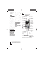
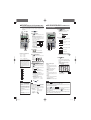
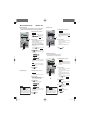
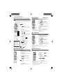
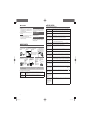
NAMES AND FUNCTIONS OF REMOTE CONTROL BUTTONS (WIRED REMOTE CONTROL)
• The figure below shows the remote control with the cover opened. Note that the items in the liquid
crystal display (LCD) area are shown for explanation purpose.
Characters displayed with dots in the liquid crystal display (LCD) area are abbreviated.
Wired remote control
Pull the cover downwards to open.
Ventilation display
Weekly timer display
Displayed during ventilation operation
See page 12
Displays the settings of the
weekly timer.
Central control display
Displayed when the air conditioning system is
controlled by centralized remote control.
Operation setting display area
Displays setting temperature, airflow
volume, operation mode and operation
message.
Timer operation display
Displays the timer operation setting.
Operation/check indicator light
During operation: Lit in green
In case of error: Flashing in red
Temperature setting buttons
Operation/stop button
These buttons are used to set the
temperature of the room.
This button is used to operate and stop
the air conditioning system.
Press the button once to operate the
system and press it once again to stop
the system.
*
Timer button
This button is used to set
the timer mode.
See page 5
MODE button
This button is used to change the
operation mode.
Timer setting buttons
FAN SPEED button
These buttons are used to set
the timer mode and the time.
See page 5 to 12
This button is used to set the airflow
volume.
VENT button
E.S.P. button
This button is used to operate external
ventilator.
See page 12
This button is used at servicing.
LOUVER button
This button is used to operate/stop the
swing louver.
See page 11
AIR CON No. button
•Display the indoor unit number connected to this
remote control.
•This button is used for indoor unit address setting.
SET button
CHECK button
This button is used to apply the timer operation setting.
See page 5 to 12
This button is used at servicing.
TEST button
This button is used during test operation.
RESET button
•Press this button while making settings to go back to the
previous operation.
See page 5 to 12
•This button is also used to reset the “FILTER CLEANING” display.
(Press it after cleaning the air filter)
IN case of FDU-F
The setting temperature of the remote controller indicates the outdoor temperature while operating thermostat ON/OFF.
PRECAUTIONS FOR WASTE DISPOSAL
Your Air Conditioning product may be marked with this symbol. It means that waste electrical and electronic
equipment (WEEE as in directive 2002/96/EC) should not be mixed with general household waste. Air
conditioners should be treated at an authorized treatment facility for re-use, recycling and recovery and
not be disposed of in the municipal waste stream. Please contact the installer or local authority for more
information.
4
PJZ012A087B.indd 4
2014-3-4 10:28:34
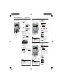
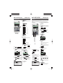
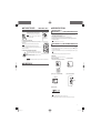
HOW TO OPERATE (Dehumidifying operation is prohibited for FDU-F.) < WIRED REMOTE CONTROL >
ATTENTION • Turn on the power supply of both indoor/outdoor units for six hours before starting the unit to protect the units. (The crankcase
is conducted and the compressor is heated) Do not turn off the power supply. (The crankcase heater is conducted while
the compressor is stopped, preventing failure of the compressor due to accumulation of liquid refrigerant by keeping the
compressor warm.)
1
Setting Fan speed Operation
mode
temperature mode
1
button.
COOL ...............26 to 28°C
4
DRY ..................21 to 24°C
FAN...................Setting unnecessary
• The settings of operation change, temperature
Operation mode
DRY
COOL
FAN
HEAT
AUTO
ATTENTION
• The display of “
”
flashes and the operation is switched to “Fan” in
the following case because the operation modes
do not match.
(1) When other indoor units are operating in different
modes (with KXR, the heat recovery system, it
is possible to operate indoor units in different
cooling/heating modes).
• Do not turn the air conditioning system on/off
frequently.
• Do not use sharp objects to press the remote
Press TEMP button.
Press
Press
LOUVER button.
See page 11 to 12
• For the louver operation
A Press
LOUVER button, and change the display to
⎦
⎡
• For the louver stopping
See page 11 to 12
A Press once while the louver is operating to display stop
positions in order.
B Press the button once more at the preffered stop position to
stop the louver at that position.
See page 11 to 12
Effective stop position
At automatic operation:................................. middle
At cooling/dehumidifying operation:.............. Horizontal
At heating operation: .................................... downwards
Press
By pressing ▼ or ▲ button, it is possible to choose the item to set.
] (set to current time)
] (The unit stops operating at each setting
time once it is set.)
[
È
] (The unit stops operating at the setting
time.)
[
È
[
] (The unit starts operating at the setitng
time.)
[
1 2 3
button
NOTE
• There may be a case that “
” is displayed when any
button mentioned in the above is pressed, but it is not a malfunction.
In that case, the operation of the button is prohibited.
• When you start to operate for the first time after turning the power
supply on, the unit starts to operate as below. You can change the
setting as you like.
Central control ......................Turned off
Operation changeover .......... With auto mode : auto cooling
Without auto mode : cooling
Set temperature ...................23°C
Fan speed ............................
Louver position .....................Horizontal
] (Timer set by one week)
È
[
] (Cancel the timer setting)
If you press the ▲ button, the display of the following timer modes
is switched in the upwards direction. If you press the
RESET button, timer mode ends and return to original satus.
FAN SPEED button.
If the indoor unit is equipped with the auto swing function, press
the
LOUVER button once and current louver status is
displayed.
If the indoor unit is not equipped with the auto swing function, the
message “
” is displayed.
Stop
] (lit)
È
3
Press
SET button.
The selected timer mode is set.
For setting of each timer mode ,See next page and thereafter.
Each timer mode can be set in parallel. The following combinations
are available.
at 4-speed
The unit operates with the maximum fan speed.
5
]
Press ▲ or ▼ button.
[
The range of fan speed modes is displayed according to the model
of indoor unit.
At 4-speed .............“
↔
↔
↔
”
↔
↔
”
At 3-speed .............“
At 2-speed .............“
↔
” or “
↔
”
At 1-speed .............The operation is invalid
HEAT ................22 to 24°C
and air flow volume adjustment can be changed
even when the air conditioner is stopped. When a
button is pressed while the operation is stopped,
the corresponding display is turned on and you can
change the setting. The display turns on for three
seconds after changing the setting, then turns off
automatically.
2
]
[
[
[
È
Press
or
button to set the room temperature.*
* IN case of FDU-F
The setting temperature of the remote controller indicates the
outdoor temperature while operating thermostat ON/OFF.
Guideline for room temperature setting
TIMER button.
Display area :
MODE button.
• With auto operation,
cooling operation
heating and cooling is
automatically changed
heating
operation
depending on difference
between the setting
temperature and room
–3
+3
room setting
temperature.*
temperature *
* IN case of FDU-F
The setting temperature of the remote controller indicates the
outdoor temperature while operating thermostat ON/OFF.
3
Press
It enters the timer mode.
“Current day of the week” and “Current time ” are displayed.
[EXAMPLE] Monday : 10 o’clock in the morning
The range of operation mode is displayed according to the model
of indoor unit.
Every time the button is pressed, the display changes in the
following order dry Æ cool Æ fan Æ heat. (Æ auto)*
(The automatic operation can be selected in case of the heat
recovery system KXR only. The automatic operation cannot be
selected in case of heat pump system KX.)
1
3
54 2
Press
< WIRED REMOTE CONTROL >
THE SELECTION OF TIMER MODE
The unit starts operating.
2
controller switches.
Press
HOW TO PERFORM THE TIMER OPERATION
Functions of each timer operation
• Sleep timer
When the setting time elapses, the unit stops operating.
10 settings are available, from “an hour later OFF” to “10
hours later OFF”.
The unit will stop when the setting time is reached.
• OFF timer
The unit stops operating at the setting time.
You can set only one time at a time.
• ON timer
The unit starts to operate at the setting time. You can set
the temperature at the same time. You can set only one
time at a time.
• Weekly timer
Up to four times of timer operation (ON timer/OFF timer)
are available for each day of the week.
Once Weekly timer is set, the unit performs the same
operation every week.
Combination of modes that can be set together
( : possible ×: impossible)
Sleep timer OFF timer
Sleep timer
OFF timer
ON timer
×
×
×
×
ON timer
Weekly timer
Weekly timer
×
×
×
×
• If you select a combination of modes that cannot be set together
SET button, the message “
and press the
(invalid operation)” is displayed for 3 seconds and then it returns
to the display selected in step 2.
ATTENTION
• If you press the
button while timer mode is operative, timer mode is finished and the display will return
to the original display. Note that the setting which has not completed is canceled.
• If you have set the ON timer mode and either the OFF timer or Sleep timer mode at the same time, the OFF timer
(or Sleep timer) shows preference to the ON timer.
• If you press the
timer button and “
” is displayed, the button can not be operated because the
button operation is disabled. If you want to make the button effective , consult your dealer.
• If you do not press any button for several minutes after pressing the
returns to the original display.
Timer button, Timer mode ends and
• If a power failure occurs, the specified timer settings will be canceled except Sleep timer. Weekly timer setting will
return to the condition that all days of the week selected as “holidays”.
5
PJZ012A087B.indd 5
2014-3-4 10:28:34
HOW TO PERFORM THE TIMER OPERATION
< WIRED REMOTE CONTROL >
SETTING THE TIME
SLEEP TIMER MODE
Timer operation is performed base on the time set by the steps described in this section. Make sure to set the
time to the current time correctly.
1
Press
After certain period has elapsed, the unit stops operating.
• Sleep timer
The unit stops operating at each setting time once it is set.
TIMER button.
1
2
7
2
Press
[
[
[
3
1 3 2
• •
5 4
•
6
3
]
[
(▼ flashes)
[
[
6
]
4
5
] (current time)
]
SET button.
The day of the week is fixed, and the flashing of ▼ mark turns to
lighting stably.
“current time” is displayed by flashing in the ON timer display area,
and “
” is displayed in the display area.
1 2•4 3•5
NOTE
• If you press
button while timer mode
is operative, timer mode is canceled and the
display will return to the original display.
• If you do not press any button for several minutes
after entering the timer mode, the timer mode
ends and returns to the original display.
SET button.
“
“
” flashes,
” lights.
Press ▲ or ▼ button.
Press
”
SET button.
Sleep timer has been set.
If the Sleep timer is set when the unit stops, it starts operating.
After “
” is displayed in the display area, it returns to
step 2.
<When “Ten hours later OFF” is set >
“
” (lights)
“
” (lights for two seconds)
È
” (lights)
“
” (lights)
“
The time left is displayed by one hour as time passes off after the
setting.
When the setting time elapses, the unit stops operating.
The unit stops operating at each setting time once it is set.
Align the ▼ mark above the day of the week to the current
day of the week.
If you press the
RESET button, the remote control will return to
the previous screen and display “
”.
”
The display changes as below. Set as you like.
“
”⇔“
”~“
”⇔“
Press ▲ or ▼ button.
Press
”Æ“
Press
]
Press ▲ and ▼ mark to move to the right and the left respectively.
4
Press ▼ button once.
[EXAMPLE]
]
SET button.
The display area shows :
TIMER button.
“
It enters the timer mode.
“Current day of the week” and “Current time” are displayed.
Display area :
Press
6
Press
ON/OFF button.
The timer mode is
finished.
OFF TIMER MODE
5
Press ▲ or ▼ button.
The unit stops operating at the setting time.
This setting is effective for only once.
1
2
Set to the current time.
If you press the
to step 1.
6
Press
RESET button, the remote controller return
Press
TIMER button.
Press ▼ button twice.
]Æ[
[
3
SET button.
Press
[EXAMPLE]
The flashing for time display turns to lighting stably, and
“
” is displayed to show that the current time is set.
Two seconds later, it returns to step 1, and “
” is
displayed.
7
Press
6 4
]Æ[
]
SET button.
“
“
” flashes,
” lights.
Press ▲ or ▼ button.
Set the time at which you want to stop the operation.
• Set “Hour”
If you press ▲ or ▼ button for a while, “Hour” display is changed
by one hour, and stops when you stop pressing.
button.
The timer mode is finished.
• Set “Minute”
If you press ▲ or ▼ button, the display increases or decreases
by ten minutes.
5
• If you press
button while timer mode is operative,
timer mode is canceled and the display will return to the
original display. Note that the setting which has not been
completed is canceled.
• If you do not press any button for several minutes after
entering the timer mode, the timer mode ends and returns
to the original display.
NOTICE If you start the operation while you are setting the OFF
timer, operate the air conditioner before setting of timer.
ATTENTION
• If you press
button while timer mode
is operative, timer mode is canceled and the
display will return to the original display.
• If you do not press any button for several minutes
after entering the timer mode, the timer mode
ends and returns to the original display.
SET button.
OFF timer has been set.
After “
” is displayed in the display area, it returns
to step 2.
<If set to 6:00 PM >
” (lights)
“
“
” (lights for two seconds)
↓
“
”(lights)
“
” (lights)
The unit stops operating at 6:00 PM.
The time display is also turned off.
1 2•4 3•5
ATTENTION
Press
6
Press
button.
The timer mode is finished.
6
PJZ012A087B.indd 6
2014-3-4 10:28:34
HOW TO PERFORM THE TIMER OPERATION
< WIRED REMOTE CONTROL >
ON TIMER MODE
WEEKLY TIMER MODE
The unit starts to operate at the set time. It is possible to set temperature at which you want to start the operation.
Selection of Weekly timer mode
One setting results in one operation only.
Up to four times of timer operation (ON timer/OFF timer) are available for each day of the week.
1
2
Note : Set time every month in Weekly timer mode.
Press
TIMER button.
Press ▼ button for three times.
] Æ [
]
[
[
10 3
8
4
1 2
•
4
•
6
3
•
5
•
7
•
9
Press
[EXAMPLE]
] Æ [
“
“
3
4
• ON timer and either Sleep timer or OFF timer are
set together, the temperature of ON timer is not
displayed.
• ON timer and either Sleep timer or OFF timer are
set together, OFF timer (or Sleep timer) shows
preference.
] Æ
”is displayed in the display area.
Press ▲ or ▼ button.
By pressing ▲ or ▼ button, it is possible to choose the item to set.
” (for setting the timer)
↕
” (for setting the selected day of the week to
holiday)
↕
Press
SET button.
Press ▲ or ▼ button.
Press
Press
“
1 2•4 3•5
ATTENTION
• If you press
button while timer mode
is operative, timer mode is canceled and the
display will return to the original display.
• If you do not press any button for several minutes
after entering the timer mode, the timer mode
ends and returns to the original display.
5
or
Press
SET button.
10 Press
button.
The timer mode is finished.
SET button.
WEEKLY TIMER SETTING
1
In the Weekly timer mode, select “
and press SET button confirm.
”
See step 1 to 5 in the above “Selection of Weekly timer mode”
“
“
2
button to set temperature.
ON timer is set, and after “
” is displayed, it returns
to step 2.
<If set to 10:00 AM >
“
”“
” (lights)
“
” (lights)
È
“
”“
” (lights)
” (lights)
“
Set temperature is displayed only in case it is set.
The unit starts to operate at setting time with set temperature.
The time display is turned off.
Press
” (for checking the timer setting and canceling
individual settings)
The selected mode is fixed.
SET button.
If you press the
RESET button, the remote control will
return to the previous screen.
• If you press the
button while timer
mode is operative, timer mode is canceled and
the display will return to the original display.
• If you do not press any button for several
minutes after entering the timer mode, the timer
mode ends and returns to the original display.
] Æ [
]
SET button.
“
If you press
or
button, the display increases or
decreases by 1°C.
Set temperature at which you want to start the operation.
9
Press
“
The left display is displayed in the display area.
<If set to 10:00 AM >
“
”(lights)
“27°C” (The current set temperature is displayed flashing)
“
” (lights)
ATTENTION
] Æ [
]Æ[
“
Press ▼ button and “
” is displayed
Press ▲ button and “
” is displayed
Select either of the above two.
• Go to step 7 if temperature is set.
• Go to step 9 if set temperature is not set.
8
Press ▼ button for four times.
Press ▲ or ▼ button.
RESET button, the remote control will
If you press the
return to the previous screen.
7
2
TIMER button.
[
[
” flashes,
” lights.
ON timer has been set.
The left display is displayed in the display area.
<If set to 10:00 AM >
“
” (lights)
” (lights)
“
6
Press
SET button.
Set the preferred time to start the operation
• Set “Hour”
If you press ▲ or ▼ button for a while, “Hour” display is changed
by one hour, and stops when you stop pressing.
• Set “Minute”
If you press ▲ or ▼ button, the display increases or decreases
by ten minutes.
5
1
] Æ
” (▼ is flashing)
” is displayed in the display area.
Press ▲ or ▼ button.
Set the ▼ mark above the day of the week to the day to be set
for timer setting. Press ▲ and ▼ to move to the right and left
respectively, ▲ and ▼ will move flashing.
If you press the ▲ button when the “▼” marks are displayed on
from “MON” to “FRI”, and then “SUN” to “SAT” (every day) with
flash, this can be used to apply the same schedule on these days.
Press
RESET button to return to “selecting Weekly
timer mode screen”, and “
” is displayed.
See the above step 3.
2•4•6•8•10
3•5•7•9•11•13
3
4
Number 1 :
Number 2 :
Number 3 :
Number 4 :
* Four operations can be set
with only ON timer or only OFF
timer.
SET button.
“▼” mark above the day of the week is switched to light, and is fixed.
“
” is displayed as the left display.
<In case Monday is set>
[EXAMPLE]
Press
Press ▲ or ▼ button.
Up to four schedules can be set for each day. Select the timer
schedule number you want to set. Set either ON timer or OFF
timer for each single operation. (See the left EXAMPLE ).
Press ▼ button to make the ◄ mark next to the number flash and
move downwards.
Press the ▲ button to move the mark upwards.
1◄
2
3
4
Press the
RESET button to return to step 1 display.
7
PJZ012A087B.indd 7
2014-3-4 10:28:35
< WIRED REMOTE CONTROL >
HOW TO PERFORM THE TIMER OPERATION
5
Press
6
Press ▲ or ▼ button.
Press ▼ button and “
Press ▲ button and “
Select either of the above two.
Press the
7
<When “
8
After “
” is displayed, “
1
Press ▲ or ▼ button.
By pressing ▲ or ▼ button, it is possible to choose the item to set.
↕
“
RESET button to return to the step 3 display.
SET button.
2
Press
” (Timer mode ends)
SET button.
In case “
” is selected, “
” is
displayed.
Repeat step 3 and onward of Weekly timer setting on page 7.
Press ▲ or ▼ button.
Press
” (selecting the next day of the week)
↕
” is displayed
Press the
” (selecting the next timer operation number
for the same day of the week)
“
” is displayed.
” is displayed.
Set the time.
9
” is displayed.
“
Press
“
” is selected>
JNext setting and Exiting Weekly timer Mode
SET button.
◄ mark next to a number is switched to light.
” or “
” is displayed.
“
The settings so far are effective and the display buttons to the left
diagram.
” is selected, “
” is
In case “
displayed.
Repeat step 1 and onward of Weekly timer setting on page 7.
RESET button to return to the step 5 display.
SET button.
In case “
” is selected, timer mode is ended.
Time display is switched to light, and is fixed.
In case of OFF timer setting, setting process is completed on
this step.
1 2
Æ
) under the day of the week which
A “_” mark is lit (
you set and the display appears as the left diagram.
Proceed to “Next setting and Exiting Weekly timer Mode” on the
right page.
” is displayed,
In case of ON timer setting, “
proceed to step 10.
10 Press ▲ or ▼ button.
Select either “
11 Press
” or “
”.
SET button.
In case “
” has been selected, ON timer setting
process is completed.
Æ
) under the day of the week which
A “_” mark is lit (
you set and the display appears as the left diagram.
Proceed to “Next setting and Exiting Weekly timer Mode” on the
right page.
In case “
” has been selected, “
is displayed; Proceed to step 12.
12 Press the temperature setting buttons
or
.
Press the
or the
button to increase or decrease by
1°C.
Set the temperature of operation starting.
Press the
13 Press
reset button to return to the display “
ATTENTION
”
”.
SET button.
ON timer setting with start-up temperature has been
completed.
The temperature display switches from flashing to lighting
stably.
Æ
) under the day of the week which
A “_” mark is lit (
you set and the display appears as the left diagram.
Proceed to “Next setting and Exiting Weekly timer Mode” on the
right page.
• If you press
button while timer
mode is operative, timer mode is canceled and
the display will return to the original display.
• If you do not press any button for several
minutes after entering the timer mode, the
timer mode ends and returns to the original
display.
• If you select a day of the week for which setting
have already been mode, all the timer numbers
that have been set are displayed. And the details
of the timer setting for the number which has “◄”
mark is displayed. You can modify the selected
setting by overwriting it.
JDisplay after Weekly timer Modes Setting
• The day of the week set is underlined.
• The ▼ mark is displayed above the current day of the week.
• The display of all the timer operation numbers set for the
current day is turned on. The ◄ mark indicates the next
setting number to be activated, and the set time is displayed.
• The timer operations are executed in order, and the number
and time display is turned off when all the timer operations
for the current day is completed.
• In case you set ON timer and OFF timer operating
at the same time, OFF timer will be effective.
• If the same two time are set for ON timer on the
same day, the lower number shows preference.
8
PJZ012A087B.indd 8
2014-4-14 14:48:53
HOW TO PERFORM THE TIMER OPERATION
< WIRED REMOTE CONTROL >
JWeekly timer Holiday Setting
JWeekly timer Checking
It is possible to disable the timer settings temporarily which has been already set by applying Holiday Set on
a particular day of the week. When the Holiday Setting is cancelled, the timer setting is enabled again.
1
1
”.
See “Selection of Weekly timer made” step 1 to 5 on page 7.
The display shows the detailed timer operation setting
information of the smallest timer operation number on the day
of the week as showm on the left. (But if not set, “
”
is displayed.)
See “Selection of Weekly timer made” step 1 to 5 on page 7.
“
4 2
” is displayed in the display area
(▼ is flashing)
” is displayed.
“
3
2
Press ▲ or ▼ button.
Move the “▼” mark displayed above the days of week to the
day which you want to set as Holiday.
Press ▲ and ▼ to move to the right and left respectively.
If you press the ▲ button when the “▼” marks are displayed on
from “MON” to “FRI”, and then “SUN” to “SAT” (every day) with
flash. This can be used in case you would like to apply Holiday
setting on these days.
3
Press
Press ▲ or ▼ button.
Detailed timer opetation setting are displayed in accordance with
the timer operation you have selected.
Press ▼ button to display from Sunday and the lowest timer
operation number.
Press ▲ button to display the settings in the reverse order.
2
In case press the
RESET button, the remote control will
return to the previous screen and display “
”.
2 3
”.
“
In the Weekly timer mode, select and set
“
In the Weekly timer mode, select and set
3
Press
button.
Timer mode ends.
SET button.
The “▼” mark above the day of the week switches from flashing
to lighting stably, the day set as a holiday is lit with ( ) , and the
following is displayed.
[
“
] (lit)
” (lit for two seconds)
JWeekly timer Mode Setting Canceling
It is possible to cancel Weekly timer mode settings of each day of the week and
“Timer Cancellation Mode” on page 10 to cancel settings of all days of week.
È
[
] (lit)
”(lit)
“
After the holiday setting has been completed, the remote control
returns to step 1. Repeat step 2 and 3 to continue setting further
holidays.
1
See “Selection of Weekly timer made” step 1 to 5 on page 7.
The display shows the detailed timer operation setting information
of the smallest timer operation number on the day of the week as
shown on the left.
NOTICE
If you set a day of the week for which no timer operation is set,
“
” is displayed for two seconds and the display returns
to the one shown in step 1.
4
Press
5
2
button.
Timer mode ends.
JCanceling Holiday Setting
1
In the Weekly timer mode, select and set
Press ▼ button to display from Sunday and the lowest timer
operation number.
“
Press ▲ button to display the settings in the reverse order.
”.
Select the timer operation number on a day of the week you
want to cancel.
2 3
•
4
Press ▲ or ▼ button.
Move the “▼” mark displayed above the day of week to the
day on which you want to cancel Holiday setting.
Select a day of the week that has been set as holiday.
3
Press
RESET button, the remote control will
If you press the
return to the previous screen, and display “
”.
3
SET button.
[
“
• If you do not press any button for several
minutes after entering the timer mode, the timer
mode ends and returns to the original display.
ATTENTION
] (lit)
[
” (lit)
“
After the holiday setting has been canceled, the remote control
returns to step 1. Repeat step 2 and 3 to continue canceling
further holiday settings.
4
Press
Timer mode ends.
button.
SET button.
” is displayed.
RESET button, the remote control will
If you press the
return to the previous screen, and display “
”.
] (lit)
” (lit for two seconds)
È
ATTENTION
Press
“
( ) display is turned off and the following is displayed.
• If you press
button while timer mode
is operative, timer mode is canceled and the
display will return to the original display.
Press ▲ or ▼ button.
Detailed timer opetation setting are displayed in accordance with
the timer operation you have selected.
See “Selection of Weekly timer made” step 1 to 5 on page 7.
2
In the Weekly timer mode, select and set
”.
“
• If you press
button while timer mode
is operative, timer mode is canceled and the
display will return to the original display.
• If you do not press any button for several
minutes after entering the timer mode, the timer
mode ends and returns to the original display.
4
Press
SET button.
“
” is displayed, and the displayed detail timer operation
settings disappears and is canceled.
È
“
” is displayed again.
Repeat step 2 to 4 to continue canceling other settings.
5
Press
button.
Timer mode ends.
9
PJZ012A087B.indd 9
2014-4-14 14:52:55
HOW TO PERFORM THE TIMER OPERATION
< WIRED REMOTE CONTROL >
TIMER CANCELLATION MODE
HOW TO OPERATE IN SILENT MODE
SILENT MODE
1
Press
TIMER button.
Timer mode begins.
The current “The day of the week” and “the current time” are
displayed.
[
“
“
7 2
1
When the silent mode is set, the unit operates more silently reducing noise from the outdoor unit.
The system applies the silent operation mode at the starting time to be set, and finish it after certain period has
passed.
Once the system is set to operate with the silent mode, the setting is applied everyday until it is canceled.
JSilent Mode Setting
1
]
”
See page 6 step 1 to 7
2
Press ▼ button for five times.
“
”
”
(▼ first press)
”
(▼ second press)
”
(▼ third press)
”
(▼ fourth press)
”
(▼ fourth press)
3
È
“
3
Press
4
Press ▲ or ▼ button.
By pressing ▲ or ▼ button, it is possible to choose the item to cancel.
“
”
↕
“
”
↕
“
”
↕
“
1 3
•
5
•
7
” (canceling all days of the week)
Press ▲ button, and the displays is switched upwards.
“
“
2
•
4
•
6
•
8
5
5
Press
” or “
” Was
SET button.
The detailed setting of selected timer mode are displayed
as shown below.
(But if not set, “
” is displayed)
<Display EXAMPLE when “
In case “
” was selected.
All the Weekly timer setting will be canceled if you proceed the
following steps.
To cancel a part of the timer setting, please see “Weekly timer
Mode Setting Canceling” on page 9.
5
Press
SET button.
The settings are displayed as shown below.
(But if not set, “
” is displayed)
” is selected>
RESET button, the remote control return to
SET button.
” (flashing)
” (lighting)
Press ▲ or ▼ button.
Set the “ON TIME”.
• Set “Hour”
If you press ▲ or ▼ button for a while, “Hour” display is changed
by one hour, and stops when you stop pressing.
• Set “Minute”
If you press ▲ or ▼ button, the display increases or decreases
by ten minutes.
RESET button, the remote control return to
If you press the
” display.
the “
RESET button, the remote control will
If you press the
return to the previous screen, and display “
”.
(step 2 above)
”,“
Press
” is displayed.
” is displayed.
The following setting is displayed.
SET button.
Timer Cancellation Mode begins.
4
” (lights)
Press ▲ or ▼ button.
If you press the
the original screen.
È
“
” or “
If ▼ button is pressed, “
If ▲ button is pressed, “
Select “
”.
È
“
SET button for three seconds or more.
“
È
“
Press
The remote control goes into silent mode setting and the following
is displayed.
È
2•4 3•5•6
In the timer mode, set the current day of the week
and current time.
”
“
In case “
selected.
< WIRED REMOTE CONTROL >
6
Press
SET button.
The ON TIME is set and the following is displayed.
“
“
JCanceling Silent Mode (Setting)
Select “
” in step 2, press
SET button and silent setting is canceled
ending the silent mode.
“
” is displayed.
“
“
” (flashing)
” (lit for two seconds)
È
” (flashing)
” (lighting)
NOTICE
If you would like to quit cancellation, press the
RESET
” display. (step 4 above)
button to return to the “
6
Press
SET button.
If you would like to quit cancellation, press the
RESET
” display. (step 4 above)
button to return to the “
6
Press
SET button to confimn.
The day of the week display area turns off, and after the
” is displayed for two seconds, and the
message “
”. (step 4 above)
display returns to “
By this operation settings, for all days of the week are canceled.
The display of the detailed timer setting is turned off, and
” is displayed for two seconds,
after the message “
“
” is displayed again. (step 4 above)
Repeat steps 4 to 6 to continue canceling timer mode settings.
ATTENTION
• If you press
button while timer mode is
operative, timer mode is canceled and the display
will return to the original display.
• If you do not press any button for several minutes
after entering the timer mode, the timer mode ends
and returns to the original display.
7
Press ON/OFF button.
Timer mode ends.
• The remote control has main-sub units, silent setting
cannot be operated with sub unit .
• After the silent mode is set, the following is displayed
for 3 seconds at the set time and the unit returns to
the original display.
At the ON time : “
”
At the OFF time : “
”
”, you can continue the
• If you select “
silent mode until it is canceled. At the first ON time,
the display shows “
” for three seconds
and returns to original display.
• If you press
button while silent
mode is operative, silent mode is canceled
and the display will return to the original
display. Note that the setting which has not
been completed is canceled.
7
Press ▲ or ▼ button to set the duration.
Select OFF time.
When you press ▲ button, and the duration is increased by two
” Æ “
” Æ “
” Æ
hours as below, “
“
”
When you press ▼ button, and the duration is decreased by two
hours.
RESET buttons, the remote control return to
If you press
the “ON TIME SET”.
8
Press
SET button.
The setting is fixed and displayed.
“
” is displayed, and the silent mode setting ends.
The setting display turns off, and returns to original display.
10
PJZ012A087B.indd 10
2014-4-16 14:42:04
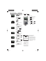
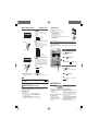
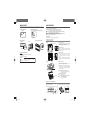
HOW TO ADJUST THE LOUVER
< WIRED REMOTE CONTROL >
It is possible to change the movable range of the louver on the air outlet from the wired remote control. Once the top and bottom position is
set, the louver will swing within the range between the top and the bottom when swing operation is chosen.
With Ceiling cassete −4 way − FDT and FDTC, it is also possible to apply different setting to each louver.
ADJUSTING WITH LOUVER BUTTON (Indoor unit with auto swing function)
Press
HOW TO SET THE AIRFLOW DIRECTION (IN CASE OF FDT, FDTC, FDE, FDK, FDFW) <WIRED REMOTE CONTROL>
LOUVER button once, and the current status of louver is displayed.
1
The display during
auto swing
Stop the air conditioner and press
SET
LOUVER button simultaneously
button and
for three seconds or more.
The following is displayed if the number of the indoor units
connected to the remote control is one. Go to step 4.
”
“
Press
È
10
The display with the
louver position fixed
”
“
The following is displayed if the number of the indoor units
connected to the remote control are more than one
“
”
È
“
2
”
Press ▲ or ▼ button.(selection of indoor unit)
Select the indoor unit of which the louver is set.
[EXAMPLE]
When you operate the swing louver
1. Press
LOUVER button, and button the display to
”.
1. Press
LOUVER button once while the louver
is swinging, and 4 stop positions are displayed every
one second in order.
”↔“
”↔“
“
“
Press
”↔
”
2. Press
LOUVER button once when the display
of the louver comes to the position you desire.
The display is switched to stop, and the position of louver is fixed.
Recommended louver fixed position
The function of the swing louver
during the heating preparation,
heating/defrost
“
” or “Heating/Defrost” is
displayed, the position of the swing louver is
automatically switched to horizontal.
COOL•DRY
2•4•6•8
1
3•5•7•9
“
No. 1
3
No. 3
HEAT
”⇔
No. 1.
For FDFW type, set louver No. 2.
Other settings selected have no
effect.
Drain hose side
Louver No.
[for FDT]
No.2
No.1
4
Press ▲ or ▼ button. (selection of louver No.)
Select the louver No. to be set according to the left figure.
[EXAMPLE]
“
”⇔“
”⇔“
“
”
No.3
No.4
Control box
Drain hose side
Piping side
”⇔
”. For FDFW, select
Note : For FDE and FDK, select “
“
”. Other louver No. settings have no effect.
Louver No.
[for FDTC]
5
When the operation is switched to normal after “The heating
preparation” or “Heating/Defrost” ends, the position of swing louver
returns to that of setting.
SET button. (determination of
[EXAMPLE]
” (lit for two seconds)
“
È
“
”
È
“
”
No. 4
Piping side
Press
indoor unit)
Selected indoor unit is fixed.
• For FDT and FDTC type, in case the
• For FDE and FDK type, set louver
horizontal position
”⇔“
No. 2
NOTICE
louver No. to be set is uncertain, set
any louver temporarily. The louver
will swing once when the setting
is completed and it is possible to
confirm the louver No. and the
position.
After that, choose the correct louver
No. and set the top and bottom
position.
”⇔“
”
“
Control box
“
When the position of the swing louver is fixed
Press
louver No.)
SET button. (Determination of
The louver No. to be set is confirmed and the display shows the
upper limit of the movable range.
NOTICE
[EXAMPLE] If No.1 louver is selected,
” ←current upper limit position
“
• Do not move the swing louver forcibly by hands for fear that it may be damaged.
• Do not blow downwards during cooling operation for a long time for fear that dew condensation may be formed at the side panel. (In
case of FDE)
6
Press ▲ or ▼ button. (selection of upper limit
position)
Select the upper limit of louver movable range.
“position 1” is the most horizontal, and “position 6” is the most
downwards.
“position --” is to return to the factory setting. If you need to change
the setting to the factory setting, use “position --”.
(upward)
(upward)
“
(downwards)
the position of the louver
” (The most horizontal)
⇔“
”
⇔“
”
⇔“
”
⇔“
”
⇔“
” (The most downward)
⇔“
” (Return to the position of shipment)
11
PJZ012A087B.indd 11
2014-3-4 10:28:39
HOW TO SET THE AIRFLOW DIRECTION
7
< WIRED REMOTE CONTROL >
Press
SET button (Fixing of the upper
limit position)
The upper limit position is fixed and the setting position is
displayed for two seconds. Then proceed to lower limit position
selection display.
[EXAMPLE]
“
” (lit for two seconds)
È
“
” (shows current setting)
8
(horizontal)
Press ▲ or ▼ button (Selection of lower limit
position)
Select the lower limit position of louver.
“position 1” is the most horizontal, and “position 6” is the most
downwards.
“position --” is to return to the factory setting. If you need to change
the setting to the factory setting, use “position --”.
the position of the louver
9
[EXAMPLE] For Upper position 2, Lower position 6
Upper
position
Movable
range
Lower
position
Note : If the upper limit position number and the lower limit
position number are set to the same position, the
louver is fixed at that position. And auto swing does
not function.
⇔“
”
⇔“
”
⇔“
”
⇔“
”
⇔“
” (the most downwards)
⇔“
” (return to the position of shipmen)
Press
position)
AIR SELECTION button can switch the air outlets.
1. Stop the air conditioner.
2. Select the airflow from AIR SELECTION button on the unit display.
A In case of selecting to upper airflow.
Press the AIR FLOW SELECTION button once.
UPPER AIR FLOW LED will light for ten seconds.
B In case of selecting to upper and lower airflow.
When UPPER AIR FLOW LED is lit by pressing AIR FLOW SELECTION button, press AIR FLOW
SELECTION button once again.
UPPER AIR FLOW LED will turn off.
HOW TO OPERATE VENTILATION (WHEN A VENTILATOR IS INSTALLED)
< WIRED REMOTE CONTROL >
When the ventilator is set to “NO VENTI LINK”, the ventilator can be turned on and off independently regardless
of the operation of the air conditioner.
When the ventilator is set to “VENTI LINK”, the ventilator operation will be interlocked with the air conditioner
operation.
” (the most horizontal)
“
(downwards)
<WIRELESS REMOTE CONTROL>
VENTILATION OPERATION NOT LINKED WITH UNIT’S
OPERATION
1
“
Stop
SET button (Fixing of the lower limit
Upper limit position and lower limit position are fixed, and the set
positions are displayed for two seconds, then setting is completed.
• After the setting is completed, the louver which was set
moves from the original position to the lower limit position,
and goes back to the original position again. (This operation
is not performed if the indoor unit and/or indoor unit fan is in
operation.)
[Example]
“
” (lit for two seconds)
È
“
”
È
“
10 Press
Press “
VENTI” button.
” is displayed, and the ventilation operation begins.
Press “
VENTI” button again.
NOTICE
• If no ventilator is connected, no operation can be performed by
pressing the ventilation button. (“
” is displayed).
VENTILATION OPERATION LINKED WITH UNIT’S OPERATION
1
Press
1
Stop
button.
button.
If a ventilator is connected, ventilation will operate automatically.
“ ” is displayed.
Press
button again.
Louver adjusting mode ends and returns to the original display.
NOTICE
NOTICE
• If you press
RESET button during settings, the display will return to previous display. If you press
button during settings, the mode will be ended and return to original display, and the settings that have not been
completed will become invalid.
• When plural remote controllers are connected, louver position setting cannot be set by slave remote control.
AIROUTLET SELECTION (IN CASE OF FDFW)
It is possible to switch between the combination of upper and lower air outlets and upper air outlet.
Not operable while the air conditioner is ON.
When the upper airflow is selected, UPPER AIR FLOW LED on the unit display will light green only under run.
<WIRED REMOTE CONTROL>
1. Stop the air conditioner.
2. Set the upper land lower limit position of the louver No.1 from the wired remote control.
For the method of changing the setting, refer to HOW TO SET THE AIRFLOW DIRECTION on page 11.
A In case of selecting to upper airflow.
Set the upper and lower limit position to UPPER 2 and LOWER 2. (No.1 UPPER 2 / LOWER 2)
B In case of selecting to upper and lower airflow.
Set the upper and lower limit position to UPPER 5 and LOWER 5. (No.1 UPPER 5 / LOWER 5)
• No operation can be performed by pressing the ventilation button.
(“
” is displayed).
FOR COMFORTABLE USE
Clean the filter frequently
See page 16
The filter should be cleaned when
the “Filter cleaning” message
is displayed, and at the end of
cooling and heating seasons.
If the filter is clogged…
• The cooling/heating capacity will get reduced. Moreover it leads
to waste of electricity and larger operation noise.
• It may cause failure.
• Dew may form and drop during cooling.
Do not block the inlet and outlet grilles of the
indoor and outdoor units.
Excessive load to the unit may cause failure.
Keep moderate room temperature
Too much cooling or heating is not good for your health. It will also
waste the electricity.
Block direct sunlight and prevent draft
Block direct sunlight with blinds and curtains during cooling. Close
the windows and doors except when ventilation is necessary.
Adjust the airflow properly
Do not expose yourself directly to the airflow for too long time. For
small animals and plants, it is harmful as well.
If you feel cold underneath your feet during heating
If the ceiling is so high that the warm airflow does not circulate
underneath your feet, it is recommended to use a circulator.
Consult your dealer for more detail.
Stop the operation and turn the power supply
off if there are any possibility of lightning
strikes during a thunderstorm.
Lightning strikes may lead to the failure of air-conditioning system.
12
PJZ012A087B.indd 12
2014-3-4 10:28:40
INSPECTION DISPLAY, FILTER SIGN, AIR CONDITIONER NUMBER, STANDBY, ROOM TEMPERATURE AND BACK UP DISPLAY
< WIRED REMOTE CONTROL >
WIRELESS REMOTE CONTROL
WHEN THE FILTER CLEANING MESSAGE IS DISPLAYED
The air conditioner stops in the event
any trouble occurs.
At the same time, the check indicator
light flashes in red and the error code is
displayed in the ON timer display area and
the following is displayed in the display
area.
The “
” is displayed
When the cumulative operation time
reaches set amount number of hours in
order to notify the time for cleaning.
”
If errors have occurred for all the connected air conditioning unit.
Initially, the error display shows the formation of the air
conditioning unit whose number is the lowest.
Errors of other air conditioning unit can be checked with the
following procedure.
1
Press AIR CON No. button.
Enter AIR CON No. display mode.
2
1
1
1
1
AIR CON No. display mode appears.
2
1
Press ▲ button.
AIR CON No. are displayed in order
from the lowest. And error codes are
displayed on the unit in trouble.
Press ▼ button to display in the
reverse order.
2
3
Press
button.
Return to the AIR CON of the lowest
number.
NOTICE
If room temperature display setting is activated, room temperature is
displayed on the remote control display. Then airflow display turns off,
but airflow adjusting button is operative. Consult your dealer for settings.
Ç
The room temperature display
14
ON/OFF button
When this is pressed once, the AIR CON starts to operate
and when this is pressed once again, it stops operating.
Every time this button is pressed, the mode is switched
as below.
HI MED LO
FILTER button
Used to reset (turn off) the filter sign.
Press the button only after completing the filter cleaning.
3
Press
button.
Return to the original display.
NOTICE
• The AIR CON No. can be displayed without relation to its modes of
operation, stop, forcible stop due to an error.
• Buttons other than “AIR CON No.” “▲” “▼” “ON/OFF” cannot be
operated.
STANDBY DISPLAY
During the first operation after breaker power supply input or the
” can be displayed on
recovery from power failure, “
the remote control for max 30 minutes.
The refrigerant oil protection control is activated to protect the
compressor and this isn’t a failure. Please wait till the display turns
off.
If the back up display appears on the screen,. Please contact the
dealer where the unit was purchased.
The back up display is indicated per 1 second at intervals of 5
seconds when the air conditioners is in operation.
Every time this button is pressed, displays switch as below
(AUTO)
(COOL)
(HEAT)
(FAN)
(DRY)
Sets room temperature by pressing
Sets time when setting the time.
or
button.
IN case of FDU-F
The setting temperature of the remote controller indicates the
outdoor temperature while operating thermostat ON/OFF.
14
14
SETTING CHANGE OF AUTOMATIC OPERATION
ACL switch
IN case of FDU-F
The setting temperature of the remote controller indicates the outdoor temperature
while operating thermostat ON/OFF.
NOTICE If the display of remote control has troubles, press RESET switch.
REPLACING THE BATTERIES
If the following occurs, the batteries are exhausted. Replace with new ones.
• When the signal is transmitted, the AIR CON does not display reception.
• The display fades away or does not show anything.
1 Pull out the cover.
2 Replace the old
batteries with
new ones.
Pay attention
to the
and
marks
(R03×2)
How to set Radio Interference
Prevention Setting
It is possible to sent two way. Press
ACL switch with AIR FLOW
button kept pressing or Insert the
batterles with AIR FLOW button
kept pressing.
ATTENTION
3 Close cover.
4 Adjust the current time.
See page 14
When any error occurs on the
display,
BACK UP DISPLAY
15
OPERATION MODE select button (Dehumidifying
operation is prohibited for FDU-F.)
ROOM* TEMP/TIME SETTING button
14
Used to cancel the TIMER SETTINGS.
• If
button is pressed once while errors are displayed,
the errors display is turned off, and return to the stop mode.
button is pressed again, the errors are displayed.
If
ROOM TEMPERATURE DISPLAY
14
WIRELESS REMOTE CONTROL HANDLING PROCEDURE
Press AIR CON No. button.
.
Indicates for two seconds when FILTER
button is pressed.
14
TIMER CANCEL button
Press ▲ button.
AIR CON No. are displayed in order
from the lowest. And error codes are
displayed on the units which have
suffered from failure in the past.
Press ▼ button to display in the
reverse order.
2
If errors have occurred for some of the connected AIR CON
units.
Only the units for which errors have occurred stop operating.
The remote control shows the operating units.
1
FILTER display
Used to reset the microcomputer.
button.
Return to the AIR CON of the lowest
number.
Press AIR CON No. button.
AIR CON No. display mode appears
and the AIR CON of the lowest number
is displayed. Other displays all turn off.
2
Press
Indicates the selected airflow volume.
FAN SPEED button
HOW TO DISPLAY AIR CON NO.
Press ▲ button.
FAN SPEED display
Indicates selected operation with
14
RESET button.
By operating AIR CON No. button, the number of the connected AIR CON
unit and error codes of the units which have the record are displayed.
2
3
Press
The cumulative operation hours is
reset and the “FILTER CLEANING”
message turns off.
AIR CON No. and error codes are
displayed in order from the lowest.
Press ▼ button to display in the
reverse order.
OPERATION MODE display
Sends signal to the air conditioner.
After cleaning
ERROR display when multiple indoor units are connected
15
Indicates set temperature.
Transmitter
1
Operation section
Air conditioner No.
” ⇔ “
“
(Air conditioner number)
Ç
(lights for 2 seconds by turns)
Clean the air filter.
See page 16
“FILTER CLEANING” is displayed in the
display area. It is displayed for one second
every five seconds while the unit is running.
It is always lit while the system stopped.
• All displays are described in the liquid crystal display for explanation
ROOM* TEMP display
Display section
WHEN THE CHECK INDICATOR LIGHT (RED) FLASHES
Error code
NAMES AND FUNCTIONS OF REMOTE CONTROL BUTTON <WIRELESS REMOTE CONTROL>
Press ACL
switch with
a ballpoint
etc.
NOTICE
If the remote control is set as “Radio
Interference Prevention Setting”, it
returns to default when the batteries
are removed. It is necessary to perform
the next procedures again.
• Do not use old and new batteries
mixed.
• Remove the batteries when the
remote control is not used for a long
time.
• The recommendable effective period
of a battery is about 6 to 12 months.
(It depends on the usage.)
• The recommendable effective
period is printed on the battery.
This may be shor ter due to
manufacturing time of the unit.
• However the battery may be still
working in order after expiry date.
When the batteries are inserted, each operation mode
is set as the right figure. Adjust the current time referring
to page 14. (The figure is for operation, and only the
current time is displayed for stopping)
Automatic operation of the KX (except KXR) cannot be
selected. When automatic operation is selected in this unit,
set the remote controller to disabled the automatic operation.
While pressing the MODE button ant then press the
ACL switch, or while pressing the MODE button and
then insert the batteries to the remote controller, then it
has been disabled the automatic operation.
ATTENTION
When the batteries are removed in the remote
controller once, the system is returned to initial
setting (automatic enable setting). In case that
removing the batteries in the remote controller,
perform the above operation once again.
HOW TO OPERATE
When you press each button of wireless remote
control, directing properly to the receiving part of
the air conditioner, the signal is transmitted. If the
air conditioner receives the signal correctly, the light
of operation indicator will flash.
ATTENTION
The operation of remote control must be performed
slowly and steadily.
ABOUT REMOTE CONTROL HOLDER
The remote control can be mounted on the wall or
pillar with the remote control holder.
Slide from the upper part of the holder to place or
take out the remote control.
ATTENTION
Do not place the remote control to the following places.
• The place exposed to direct sunlight or other strong
lighting.
• The place exposed to high temperature, for
EXAMPLE, on the electric carpet or near a stove.
If the signal receiving part of the air conditioner is
exposed to direct sunlight or other strong lighting, it
may not receive the signal. In this case, shut out the
sunlight or turn down the lighting.
Do not place anything between the remote control and the unit.
Do not operate the remote control for other electric
appliances which can be operated with a remote control.
Handle it with utmost attention.
Remove the batteries when the remote control is
not used for a long time.
Even if the remote control is not found or damaged,
you can operate the air conditioner with itself. See
“How to use the backup button” on page 15.
13
PJZ012A087B.indd 13
2014-3-4 10:28:40
HOW TO USE < WIRELESS REMOTE CONTROL >
ON – TIMER OPERATION
HOW TO OPERATE (Dehumidifying operation is prohibited for FDU-F.)
ATTENTION
Operation is started at the setting time.
• Turn on the power supply of both indoor/outdoor units for six hours before starting the unit to protect the units. (The
crankcase is conducted and the compressor is heated) Do not turn off the power supply. (The crankcase heater is conducted
while the compressor is stopped, preventing failure of the compressor due to accumulation of liquid refrigerant by keeping the
compressor warm.)
• The operation of remote control must be performed slowly and steadily.
4
2
3
Operation mode
1
Guideline of room temperature setting
HEAT ................22 to 24°C
• Operation mode can be changed even
when the unit stops.
• If you operate under the same condition
(operation mode, set temperature,
airflow, louver) just follow step 1, no
other operations are necessary. The
conditions which were set previously are
indicated on the remote control
4
Press MODE button.
Time change
OFF – TIMER OPERATION
Operation is stopped at the setting time.
[EXAMPLE] If you would like to stop the operation at PM 9:00
1
button
2
1
3
Press
button to adjust to PM 9:00.
4
Press OFF timer button.
• OFF timer display
changes from blinking to steady lighting and
the setting is completed. (Press within 60 seconds)
TIMER/CHECK display lamp of the air conditioner is lit. (The receiving part
of indoor unit)
• At PM 9:00, TIMER/CHECK display lamp turns off and the air conditioner
Cancellation
will stops operating.
• Press CANCEL button to turn off the TIMER display and timer is canceled.
• After TIMER setting, if ON/OFF button is pressed before the setting time, TIMER display turns off and the TIMER is canceled.
Time change
Press OFF TIMER button to set again.
PROGRAM TIMER OPERATION
[EXAMPLE] AM (morning) 8:00 setting
By setting both ON timer and OFF timer, the settings turn into PROGRAM timer mode. Operation and stopping can be performed at the
same time of each day by setting program timer once.
1
Press TIME SET UP switch.
2
1
2
or
button.
Set OFF timer.
Press OFF timer button and set the time with
Press OFF timer button again.
button to adjust to AM 8:00.
Morning : AM After noon : PM
The displayed time changes by 1 minutes when pressing the button.
Set ON timer.
Press ON timer button and set the time with
Press ON timer button again.
Press it with the tip of ballpoint etc. The time display blinks and can be set
to the current time.
or
button.
Both ON TIMER and OFF TIMER are displayed. The direction of arrow mark
changes depending on the status of operation.
• If
or
button is pressed during the blinking, fast-forward or
fast-backward can be done.
1· 3
or
blinks.
Displayed time will be changed by 10 minutes by pressing the buttons.
2·4
CURRENT TIME SETTING PROCEDURE
or
Press OFF timer button.
OFF timer display
3
Press AIR FLOW button.
Press
Press ON/OFF button when the air conditioner stops.
The air conditioner starts to operate.
OFF timer can be set only in case the air conditioner is in operation.
The timer is set on the current time. Adjust the current time correctly at first of all.
2
• Press CANCEL button to turn off the TIMER display and timer is canceled.
• After TIMER setting, if ON/OFF button is pressed before the setting time,
TIMER display turns off and the TIMER is canceled.
Press ON TIMER button to set again.
Press FAN SPEED button.
Press
blinks.
button to adjust to AM 8:00.
• ON timer display
changes from blinking to steady lighting and
the setting is completed.
(Press within 60 seconds)
TIMER/CHECK display lamp of the air conditioner is lit. (The receiving part of
indoor unit)
• At AM 8:00, TIMER/CHECK display lamp turns off and the air conditioner
will start operating.
Press TEMP button.
Stop
2
Press ON timer button.
In case the ON timer is set while the air
conditioner is in operation, it will be stopped
and ready for restart at the setting time.
HEAT
Effective AIR FLOW direction
see page 15
AUTO mode operation ............. Intermediate
Cooling, dehumidifying mode ... Horizontal
Heating mode .......................... Downwards
1
3
or
Cancellation
→ HI → MED → LO— FAN SPEED can be changed in order.
5
Press
1·3
Set the room temperature by pressing
or
button.*
* IN case of FDU-F
The setting temperature of the remote controller indicates the outdoor
temperature while operating thermostat ON/OFF.
DRY ..................21 to 24°C
2
button.
(The automatic operation can be selected in case of heat recovery system
KXR only. In case of KX, the automatic operation cannot be selected. In this
case, setting changes it to automatic operation.)
See page 13
COOL ...............26 to 28°C
FAN................... TEMP setting is
unnecessary
Press
(AUTO)*
COOL
FAN
DRY
3
Press ON timer button.
2
Current operation mode is indicated with the
marks besides the
operation mode icons.
The mode will change in the following order by pressing the button.
AUTO
COOL
HEAT
DRY
FAN
1
Displayed time will be changed by 10 minutes by pressing the buttons.
The operation display light (Green) turns on, and the operation starts.
The setting status is displayed on the liquid crystal area on the remote
control.
2
[EXAMPLE] If you would like to start the operation at AM 8:00
ON timer display
OPERATION
1
5
< WIRELESS REMOTE CONTROL >
(stop)
(operating)
NOTICE
• In case the buttons are not pressed for 60 seconds, the displayed time is set as
current time without step 3.
3
Press TIME SET UP switch.
The display changes from blinking to steady lighting and the setting is
completed.
Cancellation
Changing the set time
• Press CANCEL button to turn off the PROGRAM timer
display and timer is canceled. (Operation condition is kept as
before the button is pressed.)
• If ON/OFF button is pressed during TIMER operation,
TIMER display turns off and the TIMER is canceled. The air
conditioner stops operating.
Press OFF TIMER button or ON timer button to set again.
NOTICE
The same time cannot be set for OFF timer and ON timer.
14
PJZ012A087B.indd 14
2014-3-4 10:28:41
HOW TO ADJUST THE LOUVER
CHECK INDICATION, FILTER SIGN
< WIRELESS REMOTE CONTROL >
< WIRELESS REMOTE CONTROL >
UP AND DOWN ADJUSTING
for 0.5 second,
WHEN SHORT FLASHING LIGHT (Light
wink out for 0.5 second ) IS SHED FROM THE TIMER/CHECK INDICATOR LAMP (YELLOW)
How to move swing louver
Press AIR FLOW button when the air conditioner is in operation.
• The swing louver moves up and down, and the display moves too.
•
•
•
•
NOTICE
The actual movement of swing louver and that of display are not
synchronized but this is not a failure.
continuous movement of display
To fix the position of the swing louver
Press AIR FLOW button when the louver position indication comes to the position where you
would like to fix it.
• Auto swing display stops at the position and then the swing louver stops and be fixed.
Recommended air frow direction
position (when fixed)
A
NOTICE
Press the button and auto swing display stops immediately, then the swing louver stops
later, but this is not a failure. (Auto swing display and the actual louver movement of the air
conditioner are not synchronized)
COOL
DRY
B
AUTO
C
The swing louver movement during heat preparation
When “heat preparation” is displayed, the position of the swing louver
sets horizontal automatically. (The display of remote control keeps the set
position)
When heat preparation ends and normal operation starts, the position of
the swing louver returns to the set position.
HEAT
D
horizontal position
Something is wrong with the air conditioner.
Immediately after the timer/check indicator lamp flashes (light for 0.5 second, wink out for 0.5 second), the air conditioner stops.
Address No. and error code are shown on the display on the indoor unit.
The monitor display is turned off after the display time.
When nothing is displayed on the monitor, operate the remote control or press the BACKUP button resume.
Please tell your dealer “address No. and error code”, “symptom of the trouble”, “air conditioner type” and “model name” etc.
• Press ON/OFF button to stop the unit.
NOTICE
For FDTW, FDK and FDFW, address No. is not shown on display.
for 2 seconds,
WHEN LONG FLASHING LIGHT (Light
wink out for 1 second) IS SHED FROM THE TIMER/CHECK INDICATOR LAMP (YELLOW)
Clean the filter.
See page 16. 17
• When cumulative running time reaches amount number of hours, long flashing light (light for 2 seconds, wink out for 1 second) is shed
from the timer/check indicator lamp (yellow).
• After cleaning of filter, press the FILTER button on the remote control to turn off the filter cleaning sign. (Press the button for one second
or more)
NOTICE
The cumulative running time for filter sign can be changed. Consult your dealer for more information.
Detail of display
Follow the instruction mentioned below according to the indoor unit type.
ATTENTION
Do not set the position of the swing louver downwards for a long time. Dew formation on the side panel may drop.
(in case of FDE)
Ceiling cassette-4 way-(FDT)
Ceiling cassette-4 way Compact (600×600mm)-(FDTC)
FOR COMFORTABLE USE
Ceiling suspended (FDE)
TIMER
CHECK RUN
See page 12
Check monitor
Timer/check
Indicator lamp
Check monitor
Ceiling cassette - 2 way (After FDTW-KXE6F)
Timer/check Indicator lamp
Floor standing -2way- (FDFW)
Check indicator lamp
点検LED
CHECK1
CHECK2
TIMER/CHECK
Timer/check
Indicator lamp
RUN
Timer/check
Indicator lamp
Check indicator lamp
Wall mounted (FDK)
RUN TIMER/CHECK
Timer/check Indicator lamp
CHECK1 CHECK2
Check indicator lamp
NOTICE
For FDTW, FDK and FDFW, check indicator lamp “check1” / “check2” shows error code.
The number of blinking shows the error code number of tens/ones place and check1/check2 corresponds to tens/ones place.
15
PJZ012A087B.indd 15
2014-3-4 10:28:41
BACKUP BUTTON
HOW TO MAINTAIN
In time of battery exhausted, lost, trouble of remote control, the air conditioner can be operated with the BACKUP button on the indoor unit
display part.
Ceiling suspended (FDE)
Ceiling cassette-4 way-(FDT)
Ceiling cassette-4 way Compact (600×600mm)-(FDTC)
Backup button
TIMER
CHECKRUN
How to clean the Air Filter
Clean the filter frequently for economical operation.
Caution Before cleaning, stop the operation and turn off the power supply.
Otherwise, it may lead to injury as fan inside rotates at high speed.
Caution The stepladder used for removing and attaching the air filter must be fixed firmly.
Otherwise, it may lead to injury due to overturn or fall.
Caution Be careful so that the dust does not get into your eyes when removing the air filter.
Caution Do not operate the air conditioner while the air filter is removed.
Piled up dust may lead to malfunction.
How to remove
Backup button
Follow the instruction mentioned below according to the indoor unit type.
Ceiling cassette −4 way− (FDT)
Wall mounted (FDK)
Floor standing -2way- (FDFW)
• How to handle inlet grille/filter
• FDK22-56
• FDK71
<How to remove the grille>
1. Hold the stopper on the inlet grille (2 places) to the “OPEN”
direction (arrow mark A), then pull down to open the grille.
Remove the hook of the grille to dismount.
Removal
c
Backup button
Backup button
ON
OFF
Backup button
Stopper
In case of FDE/FDT/FDTC/FDK/FDFW
<How to remove the filter>
2. Push the hook of the grille in the indicated direction (arrow
mark B) to release. Then slide the filter in the indicated
direction (C) to remove.
<How to mount the filter>
ON/OFF
Press backup button and leave it untouched for two seconds.
The operation starts.
Press it again to stop the opearation.
d
e
SETTING
OPERATION MODE .......... AUTO
FAN SPEED............................ HI
TIMER ............................... No setting
SET TEMP .............................. 23°C
AUTO SWING .................... STOP (HORIZONTAL)
Hook
1. Ensure the right side and orientation of the filter and
insert it to the arrow direction (D) so that the notch
on the filter is hooked on the hook on the grille (2
places).
2. Align the hole on the filter with the hook on the grille (E 2
places) and push it securely until the filter is caught by the
hook.
The direction of filter removal
Mounting
<How to mount the grille>
Hook
1. Hang the hook on the hole on the panel. (The hook on the
grille can be hanged 3 sides on the panel.)
Hook
2. After the grille is hanged, close the grille while the stopper
on the grille (2 places) is kept pressed to “OPEN” direction.
When the grille comes to the original position, release the
stopper to hold the grille.
Hook
Caution Mount the filter to the grille securely.
Otherwise, it may lead to decreased efficiency due
to leakage of flow from the gap.
Direction for closing
Caution Mount the grille securely.
Otherwise, it may fall.
Holes for hook
Caution When the stopper is deformed or damaged,
repair or replace without delay.
Otherwise, the grille may fall.
Ceiling cassette −2 way− (FDTW-KXE6D)
1. Push one side of the inlet panel (pin A side) upward.
2. Disengage the panel from pin A.
4. Press the knobs of the air filter inward, remove the hook
area from the air conditioner unit, and remove the air filter.
3. Disengage the panel from the pin B and remove the panel.
Hook
e Disengage the pin B side.
Air filter
Pin B
c Push the pin A side upward.
d Disengage the pin A side.
Pin A
Knobs
Knobs
Air conditioner unit
Panel
16
PJZ012A087B.indd 16
2014-3-4 10:28:41
HOW TO MAINTAIN
HOW TO MAINTAIN
Ceiling cassette −2 way− (FDTW)
Wall mounted (FDK)
1. Push one side of the inlet panel (pin A side) upward.
2. Disengage the panel from pin A.
4. Press the air filter and turn the stopper to remove the air
filter.
3. Disengage the panel from the pin B and remove the panel.
e Disengage the pin B side.
2. Lightly hold the handle of the air filter , slightly lift it upward,
and then pull it out forward.
Stopper
Pin B
c Push the pin A side upward.
d Disengage the pin A side.
1. Pull up the suction grille forward.
Hold the concave sections at both the righit and left side
with your hands and pull the suction grille forward.
It stops while being open at about 60°.
Pin A
Turn
Number of stoppers
FDTW 28 - 71 6pc.
FDTW 90-140 10pc.
Panel
Caution
Install the air filter in the correct order.
<How to open, close the inlet panel>
<How to remove, install the inlet panel>
Open
Remove
Place fingers at the recesses on both sides of the panel
and pull down the panel forward so that it will be open by
about 15°.
Ceiling cassette −4 way Compact (600 x 600 mm)− (FDTC)
1. Slide the inlet grille levers in the direction of the
arrow ( ), and open it downwards.
Hooks
Floor standing -2way- (FDFW)
Hooks
Close
Push both ends evenly and press further lightly at the
center.
When removing the panel for internal cleaning or others,
open the panel, remove the string and then pull it forward.
Install
Secure the upper edge of the panel by lightly pushing it
in, place the string as illustrated and then close the panel.
2. Turn the inlet grille stopper.
3. Pull the filter toward you.
4. When the filter is put in place, insert the filter into
the hooks on the inlet grille, and be sure to return
the stopper to its original position.
<How to remove, install the filter>
5. When putting the inlet grille back in place, slide the
levers in the opposite direction and check to be
sure that the grille does not come open.
Stopper
Remove
1. Pull up the air inlet panel forwards.
2. Lightly hold the knobs at the both sides and lift a little to
remove the panel forward.
Install
1. Hold firmly the filter at the both sides as shown at right
and insert securely.
2. Close the air inlet panel.
Ceiling suspended (FDE)
1. Slide the lever of the inlet grille backward (
open it downwards.
direction) and
2. Pressing the inlet grille, press the filter to remove it from the
tab and pull it downwards.
tabs
Air filter
When mounting, press the lever forward untill it snaps.
When morrting, snab the filter into the tabs of inlet grille.
Floor standing (with casing) (FDFL)
Ceiling cassette −1 way− (FDTS)
1. Slide the lever of the suction grille in the arrow (
to open the grille.
) direction
2. While light pushing up, remove the filter from the tabs at the
left and righit, and pull towards the front.
Remove the front panel and pull the air filter out from the
bottom of the unit.
Floor standing (without casing) (FDFU)
Pull the air filter out from the bottom of the unit.
Air filter
Tab
Suction grille
Tabs
Ceiling cassette −1 way compact− (FDTQ)
1. Slide the lever of the suction grille in the arrow (
to open the grille.
) direction
2. While light pushing up, remove the filter from the tabs at the
left and righit, and pull towards the front.
Air filter
Duct connected −High static pressure− (FDU)
Duct connected −Middle static pressure− (FDUM)
Duct connected (Ultra thin) −Low static pressure− (FDQS)
Duct connected −Compact & Flexible− (FDUH)
Duct connected −High static pressure Out door Air processing unit (FDU -F)
Duct connected −Low static pressure− (FDUT)
Air filter is attached when the air conditioner is installed, so consult your dealer about how to remove or clean it.
Tab
Suction grille
Tabs
17
PJZ012A087B.indd 17
2014-3-4 10:28:42
TROUBLE SHOOTING
HOW TO MAINTAIN
How to clean
The phenomena mentioned below is not malfunction.
MAINTENANCE OF THE UNIT
1 Wash away for cleaning. If it is not so dirty, tap it or use
cleaner.
If it is very dirty, dissolve some neutral detergent in lukewarm
water (approximately 30°C), rinse the filter with it and wash
the detergent away completely.
2 After the air filter is dried, mount it to the main body and press
RESET button.
ATTENTION
• Do not dry by exposing the air filter to the direct sunlight or
using fire. Otherwise, the filter may be damaged.
• Do not operate the air conditioner with the filter removed.
Otherwise it may lead to trouble.
• Clean the unit by wiping with a piece of soft and dry cloth.
If the unit is very dirty, wipe it with a piece of cloth wet with
neutral detergent dissolved in lukewarm water and wipe it
off with clean water.
AT THE END OF THE SEASON
(after a long period of use)
• Clean the air filter and mount it.
• Clean the indoor/outdoor units.
AT THE BEGINNING OF THE SEASON
(after a long unused period)
• Inspect the air filter. If it is dirty, clean and mount it.
• Turn on the power supply button for 6 hours before
starting the operation.
Check the following items before requiring service.
THE UNIT DOES NOT WORK AT ALL
Is there a blackout or is the
fuse blown?
Is the leakage breaker
activated?
Is sunlight or other strong
illumination striking the
receive unit? (wireless unit)
OFF
POOR COOLING OR HEATING
Is the swing louver
horizontal (during
heating)?
If the swing
louver is
horizontal, the
airflow may not
reach down to
the floor.
White vapor may be generated during operation if the system is used in environment where oils and fats are
frequently used, such as in restaurants. In this case, consult the dealer and clean the heat exchanger.
The operation switched to
fan operation during cooling
operation.
The operation may switch to fan operation automatically in order to avald frost being built up on the surface of
the heat exchanger. The operation will soon return to cooling operation.
The operation switched to
fan operation during cooling
operation.(in case of FDFW
type)
In case the relative humidity is 73% or higher, the operation may alternate between fan operation and cooling
operation even though the thermostat has not been activated. The objective of this operation mode is to
prevent condensate dew formation and dew dropping from indoor unit air supply port.
The indoor fan does
not stop even when the
operation is stopped in
heating mode.
The indoor unit fan may continue operating for 40 seconds in order to remove remaining heat in the indoor
unit.
REQUESTS
Do not turn off the power supply until the fan stops.
Are there any obstacles
blocking the air inlet
and outlet grill?
During dehumidifying operation, the fan speed is automatically controlled in low speed/stop cycle in order to
avoid both drastic temperature drop and humidity rise.
The swing louver moves
without any operation.
The swing louver automatically swings twice when the power supply switch is turned on. This is not a trouble.
The louver also moves automatically to the horizontal position when “PREPARATION OF HEATING” is
displayed.
The operation mode cannot When operation mode is set to the main and sub indoor unit during the heat recovery system KXR, operation
mode of the sub unit cannot be selected.(In this case, the system conforms to operation mode of the main
be selected (in case of the
heat recovery system KXR). unit.)
POOR COOLING
NO AIRFLOW AT HEATING
• Is the direct daylight
coming into the room?
Is the unit in the
heating preparation
mode?
• Are there any
unexpected heat
sources in the
room?
No air comes out during
dehumidifying operation.
The airflow volume cannot
be changed.
The outdoor unit discharges Water or steam is discharge during defrosting operation which removes frost built up on the surface of the
heat exchanger in the outdoor unit in heating mode.
water or steam during
heating operation.
Dangerous. Immediately turn
off the power supply switch,
and contact your dealer.
ON
Is the air filter clogged?
The supply air from the indoor unit may smell bad if the smell of cigarettes, cosmetics and/or furniture has
saturated the air conditioning system.
White vapor is generated
from the indoor unit during
operation.
The air conditioning system During the first 3 minutes after stopping operation, it is not possible to perform cooling, dehumidifying or
cannot start operating again heating operation even if the ON/OFF button is pressed to indicate “operation.” This is because a circuit for
immediately after stopping. protecting the compressor is activated (the fan is operating during this period).
TROUBLE SHOOTING
Is the power supply switch
turned off?
The supply air from the
indoor unit smells bad.
See page 18
• Are there too many
people in the room?
If, after checking the items above, the air conditioner still does not operate normally or in the next cases, stop operating and contact your dealer.
• If the fuse and breaker blow frequently. • If water drips at cooling/dehumidifying operation. • If the operation or operation noise is abnormal.
• If the check indicator light flashes.
The phenomena mentioned below is not malfunction.
The air conditioning system
sounds as if water is
draining from it.
Sounds of rustling or gurgling may be heard when the operation is started, when the compressor is activated/
deactivated during operation, or when the operation is stopped. These are the sounds of the refrigerant
flowing through the system.
Sounds of rustling or
gurgling may be heard from
a stopped indoor unit.
These sounds can be heard when the air conditioning system is performing automatic control.
The outdoor unit fan is not
running even when the
system is in operation.
The fan speed is automatically controlled according to the ambient temperature. It may be stopped in high
ambient temperature in case of heating, and in low ambient temperature in case of coding. Also, the fan is
stopped during defrosting operation.
Slapping sounds are heard.
These sounds are generated when plastic components are expanded or shrunk by the heat and rubbed with
each other.
REQUESTS
The fan will suddenly begin to operate even if it is stopped. Do not insert finger and/or stick.
Hissing sounds are heard These sounds are generated when the refrigerant valve inside the air conditioning system is activated.
when the operation is
stopped or during defrost
operation.
The air conditioner starts In case the automatic restart function is enabled, and when the power supply recovers, the system restarts
See below
operation automatically as the operation automatically as same condition as before power supply is cut.
soon as the power supply is
turned on.
The setting temperature If changing the set temperature is prohibited on the remote control, it is not possible to change the
See right
cannot be changed (the temperature setting even T or S is pressed.
setting temperature display
flashes).
The airflow becomes weak When you switch the operation mode from Cool to Heat or from Heat to Cool during operation, the airflow
if the operation mode is becomes weak for 3 minutes.
changed during operation
(in case of the heat recovery
system KXR).
In case of wirless remote In case the system is controlled by the other centralized remote control and it forbids operating the system
control, the unit does not from the remote control, it is not possible to operate by the remote control.
operate with the inspection
display light on the indoor
unit flashing even though
any button on the remote
control is pressed.
18
PJZ012A087B.indd 18
2014-3-4 10:28:42
PREPARATION OF HEATING
CASES WHEN “
(PREPARATION OF HEATING)” IS DISPLAYED
“
(PREPARATION OF HEATING)” is displayed in the remote control display area in the following cases.
For wireless devices, the run/check display lamp on the main body display unit will flash green.
Setting temperature and preparation of heating are displayed on the wired remote control.
• At Starting Heating Operation
In order to prevent cool air from blowing out, the airflow into the room may be stopped depending on the room temperature at the
start of heating operation. please wait for a while and the operation automatically switches to the normal heating operation.
• At defrost operation (during heating operation)
When frost may easily formed on the outdoor unit, the heating operation automatically is stopped (both indoor/outdoor unit
stop fan operation) for approximately 5 to 10 minutes per hour and defrosting is operated. After the defrosting is complete, the
operation automatically switches back to the normal operation.
SETTING TO DISABLE BUTTON OPERATION <Wired remote control>
ATTENTION
The following button operations can be disabled. If the button is pressed, “
returns to original display. Consult your dealer for “
” setting.
1
button
TEMP button
2
3
LOUVER button
4
MODE button
5
FAN SPEED button
TIMER button
6
” is displayed provided the button is disabled, and
INSTALLATION, RELOCATION, AND INSPECTION MAINTENANCE
Please observe the following points in order to use the air conditioner in a safe and comfortable manner.
Make sure to request your dealer for installation, never try to do so by yourself.
HEATING OPERATION
• Heat pump type
Heat pump type heating is the heating mechanism in which the refrigerant takes in outer temperature to supply heat into the room.
• Defrost operation
During heating with a heat pump type air conditioner, frost will be formed on the outdoor unit if the temperature outside the room drops. If left alone, the
heating efficiency decreases. In order to deal with this, the operation is automatically switched to defrost operation to remove the frost. During the period, the
airflow of indoor/outdoor unit is stopped and “heating defrost” is displayed.
• Outer air temperature and heating capacity
The heating efficiency of heat pump type air conditioner decreases as the outside temperature becomes lower. If the capacity of air conditioner for heating
is not sufficient, please use other heating device.
• Time required until the room temperature increases
A heat type air conditioner circulates warm air to warm the entire room, so it takes a while to rise up the room temperature. It is recommended to start operation
earlier on a very cold day.
• When room temperature adjusting device operates during heating
If room temperature rises and the room temperature adjusting device is activated, the airflow becomes automatically low. When the room temperature
drops, it switched back automatically to the normal operation.
AUTO RESTART <WIRED REMOTE CONTROL>
NOTICE
The remote control has a auto restart function, and can be activated. (Inactivated at shipment).Consult your dealer.
What is auto restart
• When a power failure occurs or the power supply is turned off, the function allows the system to automatically resume operation with the remote control
setting made set before the power failure when the power supply recovers. If the system is stopped before power failure it remains stopped after the power
recover.
• Note that in the following cases it is needed to set again with the remote control.
1Timer setting is cancelled. But the sleep timer recovers after power failure recover. Weekly timer settings, however, recover with all days holiday setting.
And time setting returns to default. To return to original setting, after time setting, execute “holiday cancel”.
2Louver stops at the horizontal position.
ATTENTION
When the auto restart is activated, be sure to stop operation and turn off the power supply. (if the power supply is turned off while the system is operating,
the fan of the indoor unit will begin rotating immediately after the power supply is turned on. And the outdoor unit will start operating approximately 3 minutes
after it is ON.)
INSTALLATION LOCATION
Is the system installed in a well-ventilated place?
Are there any obstacles? If so, it leads to the decrease of the efficiency and the increase of operation noise.
Avoid the place where cool/warm air and operation noise cause problems to your neighbors.
ELECTRICAL WORK
Caution : Make sure to perform grounding work
Do not connect the ground wire to any gas pipe, water pipe, or wires of lightning conductors and telephones.
If the ground work is not good, it may lead to electric shock.
Caution : Make sure to mount a leakage breaker
If it is not mounted there, it may lead to electric shock.
Electrical installation work must be performed by an electrical installation service provider qualified by a power provider of the country. Electrical installation
work must be executed according to the technical standards and other regulations applicable to electrical installations in the country.
Is the wiring designated for the air conditioner?
Is the remote control mounted correctly?
• In the case of exposed wiring, is the wiring fixed with the attached screw?
• Is the attached remote control clamps used for fixing the remote control cord?
• Is the remote control mounted at a height where children cannot reach?
RELOCATION
Warning : Make sure to consult a dealer or specialist if it is required to relocate and reinstall the air conditioning system.
If the air conditioning system is installed incorrectly, water leakage, electric shock and/or fire may occur. Note that an installation fee will be
charged for relocation and installation.
INSPECTION MAINTENANCE
Normally the efficiency of the air conditioning system will become lower after a while, because dirt accumulates inside the system. This occurs gradually in
around 3 years of use , depending on the condition of use and surrounding enviroment. It is thus necessary to conduct inspection maintenance in addition
to regular maintenance. We recommend you to consult the dealer from whom you purchased the system and make a contract for periodical inspection.
(charged).
OPERATION RANGE
ATTENTION
Please use the system in the following operation range. If the system is operated outside this range, the protection controls may be activated to prevent
malfunction.
Condition
Operation
Cooling
operation
Dry operation
Heating
operation
Room temperature
Temperature outside the room
Humidity inside the room
Approximately
21 to 32°C
Long continuous operation under
approximately 21°C may lead to malfunction
due to dewfall
Approximately -15 to 43°C
Approximately 80% or less
Long operation under high humidity may leads to
waterdrop or smoky vapor at the supply air grille.
Approximately
27°C or less
Approximately
-20 to 21°C
If outside air temperature becomes low, the
heating efficiency is lowed and the heating
becomes difficult.
(Note) Operation range may differ depending on models .Please check the catalog.
FDU-F
Condition
Operation
Outdoor air temperature
Cooling
operation
20 ~ 40°C (32°C wet-bulb) Dry-bulb
Heating
operation
-10 ~ 24°C Dry-bulb
19
PJZ012A087B.indd 19
2014-3-4 10:28:42
20
PJZ012A087B.indd 20
2014-3-4 10:28:43
AIR-CONDITIONING & REFRIGERATIONS DIVISION
3-1, Asahi, Nishibiwajima-cho, Kiyosu, Aichi, 452-8561, Japan
http://www.mhi.co.jp
MITSUBISHI HEAVY INDUSTRIES AIR-CONDITIONING EUROPE, LTD.
7 Roundwood Avenue, Stockley Park, Uxbridge, Middlesex, UB11 1AX, United Kingdom
Tel : +44-20-7025-2750
Fax : +44-20-7025-2751
http ://www.mhiae.com
MITSUBISHI HEAVY INDUSTRIES AIR-CONDITIONERS AUSTRALIA, PTY. LTD.
9C Commercial Road Kingsgrove NSW 2208 PO BOX 318 Kingsgrove NSW 1480
Tel : +61-2-8571-7977
Fax : +61-2-8571-7992
http ://www.mhiaa.com.au
MITSUBISHI HEAVY INDUSTRIES - MAHAJAK AIR CONDITIONERS CO., LTD.
220, Soi Chalongkrung 31,
Kwang Lamplatiew, Khet Lad Krabang, Bangkok 10520, Thailand
Tel : +66-2-326-0401
Fax : +66-2-326-0419
http ://www.maco.co.th/
PJZ012A087B_cover.indd 2
2014-4-14 14:47:36