1
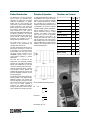
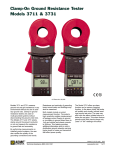
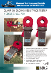
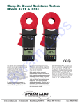
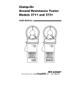
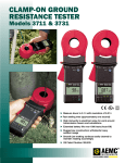
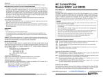
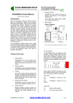
Clamp-On Ground Resistance Testers
Models 3711 & 3731
US Patent No: 362,639
Description
Models 3711 and 3731 measure ground
rod and small grid resistance in any
environment without the use of auxiliary
ground rods. Clamp-on ground
resistance testers are used in multigrounded systems without disconnecting
the ground under test. The Models 3711
and 3731 simply clamp around the
ground conductor or rod and measure
the resistance to ground.
By performing measurements on intact
ground systems, the user also verifies
the quality of the grounding connections
and bonds. Resistance and continuity of
grounding loops around pads and
buildings may also be measured.
Both models include a current measurement function. The probe’s high
sensitivity enables measurement of
leakage current flowing to ground or
circulating in ground loops down to 1mA
and neutral currents to 30Arms. This
feature provides additional information
which is becoming vital as distribution
ground networks carry higher levels of
noise and harmonics, which affect
power quality.
The Model 3731 offers an alarm function
and a memory (logging) function. In the
alarm mode, the probe will audibly and
visually indicate if the reading is beyond
an input set point. The user may also
have the alarm initiated above or below
the set point. This alarm feature permits
quick field checks where only “pass” or
“fail” readings will suffice.
Features
◆ NEW – Third generation of clamp-on
ground testers
◆ NEW – Replace Models 3710/30 with
TEN TIMES the resolution (measure
0.1Ω grounds!)
◆ HIGHER immunity to electrical noise
for work around transmission towers
and substations
◆ BETTER power management for
extended battery life
◆ NEW – all new parts, design and
manufacturing process for lower costs
◆ SAME external design, reliability and
operation as previous Models 3710/30
◆ Simple and fast clamp-on operation no leads, no auxiliary rods or spacing
requirements
◆ Direct reading of ground resistance
from 0.01Ω to 1200Ω
◆ Direct reading of continuity and
ground loop resistance
◆ Direct reading of ground leakage
current from 1mA to 30Arms
◆ Jaw design with large 1.25" (32 mm)
window accommodates up to 1000
MCM cables
◆ Auto-off for power management
◆ Alarm function with adjustable set point
and buzzer for quick field checks
◆ Memory function to store 99 field measurements for later retrieval and analysis
◆ Meets IEC 1010 Cat. III and CE marked
◆ Designed to UL and CSA standards
(agency approvals not available at
time o document)
◆ Rugged Lexan® head and body construction with free three-year warranty
◆ Alarm settings and stored memory
information saved during shutdown
◆ Patented design
Applications
◆ Measure ground rod and small grid
resistance
◆ Use in multi-grounded systems without
disconnecting the ground under test
◆ Measure resistance and continuity of
grounding loops around pads and
buildings
◆ Measure leakage current flowing to
ground or circulating in ground loops
◆ Conduct quick field checks
◆ Conduct field surveys and retrieve
and analyze readings at a later time
Product Construction
Principle of Operation
The Models 3711 and 3731 bodies are
built of Lexan® (or equivalent polycarbonate) for rugged use. The probe
heads are encapsulated in a doublewalled shell for extra strength and
reinforced for enhanced field reliability.
Overall construction and mechanical
design ratings such as drop test, shock
and vibration, weatherproofing against
water projections or dust, meet or
exceed IEC (International Electrotechnical
Commission) standards. The products
have been designed to IEC 1010 Cat. III
and to meet UL, CSA and GS safety
approvals (not available at time of
printing). Both models CE marked.
A multigrounded distribution system may
be represented as a simple circuit (see
Figures 1 and 2). If a voltage E is applied
with a special transformer (in the jaw)
to a grounding rod or conductor Rx, a
resulting current I flows through the circuit.
The probe head, or jaw, is a key
component in the measurement and
overall product performance.
In the Models 3711 and 3731, a constant
2.403kHz voltage oscillator generates E,
and the resulting current I is fed to a
special transformer through a power
amplifier. The receiver current probe
picks up the current at the generated
frequency flowing in the system. An
internal filter eliminates earth currents
and high frequency noise. If the current I
that is flowing in the circuit is measured
with the voltage E kept constant, then the
resistance E of the ground Rx may be
obtained and displayed.
The large jaw thickness permits use on
tight ground conductors on poles and
in manholes. The 1.25" (32mm) opening
accommodates not only ground rods,
but larger ground conductors (up to
1000MCM) typically found in telecommunication buildings or railroad
applications.
The inner jaw is composed of two
independent and individually shielded
magnetic cores permitting measurement
without noise interference or cross talk
common to separate probe instruments.
Figure 1
Thorough mechanical design, including
small winglets, ensures reliable and
repetitive jaw alignment for accuracy and
prevents undesirable insertions into the
jaw spring assembly.
The ergonomic body design permits onehanded operation. The guard provides
additional strength, and prevents the
hand from slipping or coming into contact
with conductors under test. The LCD lens
cover may be easily replaced if
scratched. The sealed push-buttons
directly access all test functions and are
easily operated even with gloved hands.
Figure 2
We may establish the following equation:
E/I = Rx +
1
n
1
∑ Rk
k=1
where Rx >>
1
n
1
∑ Rk
k=1
and therefore, E/I ~= Rx.
Functions and Features
3711
3731
Ohms Range
Yes
Yes
Arms Range
Yes
Yes
Hold Function
Yes
Yes
Self Testp
Yes
Yes
Auto-Off
Yes
Yes
Battery Life Indicator
Yes
Yes
Noise Indicator
Yes
Yes
Open Jaw Indicator
Yes
Yes
Closed Loop Indicator
Yes
Yes
Multi-Tone Beeper
Yes
Yes
Alarm Function
–
Yes
Memory (Logging)
–
Yes
Specifications
ELECTRICAL
Ground Resistance Ranges: Autoranging 0.01Ω to 1200Ω
Meas.Range
0.10 to 1.00
1.0 to 50.0Ω
50.0 to 100.0Ω
100 to 200Ω
200 to 400Ω
400 to 600Ω
600 to 1200Ω
Resolution (r)
0.01Ω
0.1Ω
0.5Ω
1Ω
5Ω
10Ω
50Ω
± 3% Rdg. ± 2r
± 6% Rdg. ± 2r
± 10% Rdg. ± 2r
N/A
Accuracy
± 2.5% Rdg. ± 2r ± 1.5% Rdg. ± 2r ± 2% Rdg. ± 2r
Current Measurement Ranges: Autoranging 1mA to 30.00Arms
Meas.Range
1 to 299mA
0.300A to 2.999A
3.00A to 29.99A
Resolution (r)
1mA
0.001A
0.01A
± 2.5% Rdg. ± 2r
± 2.5% Rdg. ± 2r
± 2.6% Rdg. ± 2r
Accuracy
ELECTRICAL
MECHANICAL
SAFETY
Resistance Measurement Frequency:
2403kHz
Dimensions: 9.25" x 3.94" x 2.17"
(235mm x 100mm x 55mm)
IEC 1010-1 Double Insulation
Current Measurement Frequency:
1Ω to 199Ω
Weight: 2.2lbs. (1kg)
Current Overload:
OL displayed above 30Arms
Power Supply: 9V Alkaline battery
(IEC 6LF22 or NEDA 1604A)
Battery Life: typical: 8 hours or approx.
1,000 measurements of 30 seconds
Case Material: Lexan® 9 2 0 Ao r
equivalent (UL94V2)
Environmental: IP30, IEC 359 Group III
Vibration Test: IEC 68-2-6
Shock Test: IEC 68-2-27
Jaw Cover Material: Lexan® 500R with
10% fiberglass charge (UL94V0)
Drop Test (1m): IEC 68-2-32
LCD Cover Material:
Lexan® 920A(UL94V1)
Working Voltage:
150V, Cat. III - Pollution Degree 2
300V, Cat. III - Pollution Degree 1
Color: Gray body, red jaws
Jaw Window Diameter: 1.25" (32mm)
Dielectric Test: 2500VAC
Max Overload (A or Ω Function):
100A continuous, 200A (<5s) 50/60Hz
Jaw Opening: 1.38" (35mm)
Operating Temperature:
14 to 131°F (-10° to 55°C)
Operating Humidity: 0 to 90% RH @
14 to 104°F (-10°C to 40°C), 75% RH
@ 131°F (55°C)
Storage Temperature:
-40 to 158°F (-40°C to 70°C)
LCD: 3-3/4 Digit, 1.73" x 1.10"
(44 x 28 mm)
U.S. Patent: No. 362,639
NSN: 6625-01-377-8030
Large inner jaw diameter fits rods and
conductors up to 1000 MCM
Display
Push Buttons
Ω
Displayed when measuring
resistance
mA, A
Displayed when measuring
current
ON/OFF
Power ON or power OFF.
Activates display self test at power-up
100%
Percentage of battery life
remaining
Flashing indicates low battery
condition
P indicates the auto-off feature
is inactive
HOLD push button has been
pressed
HOLD
Active beeper function
NOISE
Noise in the reading
Probe jaws not closed properly.
Ω
Resistance measurement. (Increment
the alarm set point and the memory
position when in programming mode.)
A
Current measurement. (Decrement the
alarm set point and the memory position
when in programming mode.)
AL (3731 only)
Activate/deactivate the alarm function.
Access the value of the alarm set point
when in programming mode
MEM (3731 only)
Activate the memory function or to
read the stored values in MR (Memory
Recall). Clears the memory when in
programming mode
Alarm setpoints
MEM
Memory function active
MR 88
Memory Recall (MR) & register
R<1Ω
Resistance measured is
below 1Ω
Calibration Check Loop (included)
ORDERING INFORMATION
1.
2.
3.
4.
5.
6.
7.
8.
9.
Head assembly
Hold button
Display
On/Off
Ω: Resistance measurements
A: Current measurements
Lever opens & closes jaws
AL: Alarm button (3731 only)
MEM: Memory button (3731 only)
Clamp-on Ground Tester
Models 3711 & 3731 are packaged with
calibration loop, battery and user manual
in hard carrying case.
CATALOG NO.
Clamp-on Ground Resistance Tester Model 3711 . . . . . . . . . . . . . . . . . . . . . . . . . . . . . . . . . . . . . . . . . . . . . . . Cat.#2117.60
includes hard carrying case, 9V Alkaline battery, 25Ω calibration check loop, and user manual
Clamp-on Ground Resistance Tester Model 3731 . . . . . . . . . . . . . . . . . . . . . . . . . . . . . . . . . . . . . . . . . . . . . . . Cat.#2117.61
includes hard carrying case, 9V Alkaline battery, 25Ω calibration check loop, and user manual