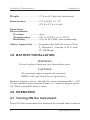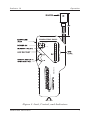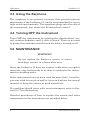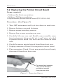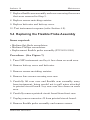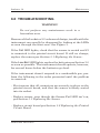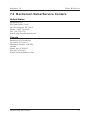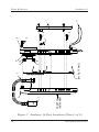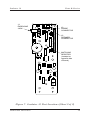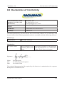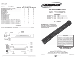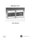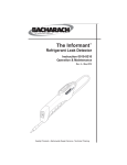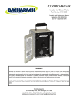
1
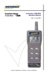
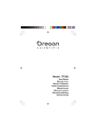
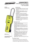
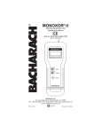
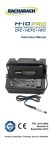
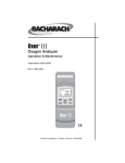
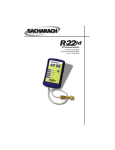
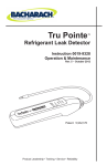
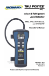
LEAKATOR® 10
INSTRUCTION 0019-9167
COMBUSTIBLE GAS DETECTOR
Part No. 0019-7051
Rev. 18 – October 2012
WARRANTY
Bacharach, Inc. warrants to Buyer that at the time of delivery
this Product will be free from defects in material and manufacture and will conform substantially to Bacharach Inc.’s applicable specifications. Bacharach’s liability and Buyer’s remedy
under this warranty are limited to the repair or replacement,
at Bacharach’s option, of this Product or parts thereof returned
to Seller at the factory of manufacture and shown to Bacharach
Inc.’s reasonable satisfaction to have been defective; provided
that written notice of the defect shall have been given by Buyer
to Bacharach Inc. within one (1) year after the date of delivery
of this Product by Bacharach, Inc.
Bacharach, Inc. warrants to Buyer that it will convey good title
to this Product. Bacharach’s liability and Buyer’s remedy under
this warranty of title are limited to the removal of any title defects or, at the election of Bacharach, to the replacement of this
Product or parts thereof that are defective in title.
THE FOREGOING WARRANTIES ARE EXCLUSIVE AND
ARE GIVEN AND ACCEPTED IN LIEU OF (I) ANY AND ALL
OTHER WARRANTIES, EXPRESS OR IMPLIED, INCLUDING
WITHOUT LIMITATION THE IMPLIED WARRANTIES OF
MERCHANTABILITY AND FITNESS FOR A PARTICULAR
PURPOSE: AND (II) ANY OBLIGATION, LIABILITY, RIGHT,
CLAIM OR REMEDY IN CONTRACT OR TORT, WHETHER
OR NOT ARISING FROM BACHARACH’S NEGLIGENCE,
ACTUAL OR IMPLIED. The remedies of the Buyer shall be
limited to those provided herein to the exclusion of any and
all other remedies including, without limitation incidental or
consequential damages. No agreement varying or extending
the foregoing warranties, remedies or this limitation will be
binding upon Bacharach, Inc. unless in writing, signed by a duly
authorized officer of Bacharach.
Copyright © 1994-2012 by Bacharach, Inc.
A
Leakator 10
WARNING!
Because this instrument is used to detect and monitor materials and
conditions which are listed by OSHA or others as potentially hazardous to personnel and property, the information in this manual
must be fully understood and utilized to ensure that the instrument
is operating properly and is both used and maintained in the proper
manner by qualified personnel. An instrument that is not properly
calibrated, operated and maintained by qualified personnel is likely
to provide erroneous information, which could prevent user awareness
of a potentially hazardous situation for the instrument user, other
personnel and property.
If, after reading the information in this manual, the user has questions
regarding the operation, application or maintenance of the instrument,
supervisory or training assistance should be obtained before use. Factory assistance is available by calling 1-800-736-4666.
WARNING!
The Leakator 10 is not to be used in any application that is beyond
its intended purpose or beyond the scope of its specifications. Failure
to follow this warning can result in personal injury or damage to the
equipment. For details on appropriate use, refer to the general description, application, and operation discussions in this manual.
Instruction 0019-9167
i
Leakator 10
CONTENTS
Page
1.0 INTRODUCTION ........................................................ 1
2.0 TECHNICAL CHARACTERISTICS ........................... 3
3.0 BATTERY INSTALLATION ....................................... 5
4.0 OPERATION ................................................................ 6
4.1
4.2
4.3
4.4
Turning ON the Instrument ............................ 6
Taking a Gas Reading ...................................... 6
Using the Earphone ......................................... 8
Turning OFF the Instrument .......................... 8
5.0 MAINTENANCE ......................................................... 9
5.1
5.2
5.3
5.4
Replacing the Sensor........................................ 9
Replacing the Printed Circuit Board............. 12
Replacing the Speaker ................................... 13
Replacing the Flexible Probe Assembly .........14
6.0 TROUBLESHOOTING ............................................... 16
7.0 PARTS/SERVICE........................................................ 17
7.1 Parts List ......................................................... 17
7.2 Bacharach Sales/Service Centers ................... 20
8.0 DECLARTION OF CONFORMITY ........................... 21
ii
Instruction 0019-9167
Leakator 10
Introduction
1.0 GENERAL DESCRITPION AND USE
The Leakator 10 is an intrinsically safe, battery-powered
portable instrument designed to primarily detect the source
of combustible-gas leaks. The instrument is ideally suited
for heating service contractors, utility personnel, and other
users who are interested in pinpointing gas leaks, and testing gas appliances in residential, commercial and industrial
installations.
The instrument is supplied with a durable plastic carrying
case, 20" probe and instruction manual.
The Leakator 10 features:
• Ten bright-red LEDs and a speaker that provide visual
and audible indications to the presence of gas.
Figure 1. Leakator 10
Instruction 0019-9167
1
Introduction
Leakator 10
• Three operation-status LEDs that show power on, sensor
operation, and low battery.
• A 20-inch flexible probe.
• Simple thumb wheel on/off and gain control allowing onehanded operation.
• A solid-state sensor that has a typical life of 5 years.
• A battery capacity of 30 hours under normal use conditions.
• The ability to detect natural gas (methane) in concentrations
as low as 20 ppm. In addition, the following gases and vapors
are also detectable:
Acetone
Acetylene
Ammonia
Benzene
Butane
Ethanol
Ethylene Oxide
Gasoline
Hexane
Hydrogen
Industrial Solvents
Paint Thinners
Propane
Naphtha
WARNINGS!
For safety reasons, the Leakator 10 must only be operated
and serviced by qualified personnel. Read and understand
the contents of this instruction manual before operating
or servicing.
To prevent ignition of a hazardous atmosphere, do not
perform any maintenance work, such as replacing the instrument’s batteries, sensor, or sensor-matching resistor,
in an area classified as being hazardous.
2
Instruction 0019-9167
Leakator 10
Technical Characteristics
2.0 TECHNICAL CHARACTERISTICS
Power
..........................Five C-size Alkaline Batteries.
Battery Life ..................Approximately 30 hours of continuous operation under normal-use
conditions.
Sensor:
Type ...........................Solid State, plug-in replacement.
Life Expectancy ......Typically 5 years.
Calibration ..............No user calibration required.
Probe .............................Self storing 20" (51 cm) flexible
probe, includes integral sensor.
Response Time ............Less than 3 seconds to full scale
indication.
Sensitivity ....................20 ppm Methane.
Warm-Up Time ............Approximately 25 to 55 seconds.
Duty Cycle ....................Continuous with no limitation.
Gas Indication .............Visual: 10 red ultra-bright LEDs.
Audible: Variable speed ticking
sound (earphone provided for use
in noisy environments).
Status LEDs .................Power On (green)
Sensor Failure (yellow)
Low Battery (yellow)
Instruction 0019-9167
3
Leakator 10
Technical Characteristics
Weight ...........................17.8 oz (0.5 kg) (w/o batteries)
Dimensions: ..................8.5" x 2.25" x 1.75"
(21.6 x 5.7 x 4.4 cm)
Operating
Environment:
Position ..................Any
Temperature ..........23° to 130°F (–5° to 54°C)
Humidity .................10% to 90% RH, non-condensing
Safety Approvals .........Intrinsically Safe for use in Class
I, Division 1, Groups A, B, C and
D. CE Mark.
3.0 BATTERY INSTALLATION
WARNING!
Do not replace batteries in a hazardous area.
CAUTION:
To maintain agency approval, use only
NEDA-14A type batteries or equivalent.
Remove battery cover. Install five (non-rechargeable) 1.5V
C-size alkaline batteries per Figure 2 – observe proper polarity. Then reinstall battery cover.
4.0 OPERATION
4.1 Turning ON the Instrument
Turn ON the instrument by rotating its thumb-wheel switch
4
Instruction 0019-9167
Leakator 10
Battery Installation
(Fig 3) clockwise until a click is heard. Observe the following:
• The Power LED lights.
• The Fail LED will light, but should turn off in a few seconds if the sensor is good and properly seated in its socket.
• If the Low Bat. LED is on, replace the batteries per Section
3.0 Battery Installation.
After the instrument stabilizes, rotate the Gain control in the
direction necessary to cause the bottom Gas Level LED to
just turn off. Be sure to always set this control in the same
environment you intend to test in.
The instrument is now ready for use.
Figure 2. Battery Installation
Instruction 0019-9167
5
Operation
Leakator 10
4.2 Taking a Gas Reading
To verify that the instrument is operating, sample a known
combustible gas (e.g., a gas-air mixture from an unlit burner
of a natural-gas range). If no response is observed or heard,
refer to Section 6.0 Troubleshooting.
Important! The sensor becomes less sensitive
after being exposed to an excessive amount of
gas. Therefore, after testing the instrument as
described above, leave it on for several minutes
to restabilize the sensor.
Take a gas reading by positioning the end of the instrument’s
flexible probe near the area to be sampled.
The presence of a combustible gas is indicated by a column of
ten red LEDs and a speaker. The number of lighted LEDs gives
visual indication of the relative gas level, while the speaker
produces clicking sounds, similar to a Geiger counter, that
increase in repetition rate as the gas concentration goes up
in relation to the instrument’s gain setting.
The instrument’s sensitivity to gas concentrations is adjusted
by means of its thumb-wheel Gain control. Clockwise rotation
increases sensitivity, while counterclockwise rotation decreases
sensitivity. The Gain control is useful in pinpointing large leaks
by starting with the control set to light 1 or 2 LEDs, and then
gradually rotating the control counterclockwise as the probe
gets closer to the leak.
6
Instruction 0019-9167
Leakator 10
Operation
COMBUSTIBLE GASES
Powe r
Fail
MADE IN USA
Low Bat.
Figure 3. Jack, Control, and Indicators
Instruction 0019-9167
7
Leakator 10
Operation
4.3 Using the Earphone
The earphone is an optional accessory that provides private
monitoring of the Leakator 10, and is recommended for use in
high-noise environments. The earphone plugs into the side of
the instrument, just above the thumb-wheel control.
4.4 Turning OFF the Instrument
Turn OFF the instrument by rotating the thumb-wheel control counterclockwise until a click is heard. There is no need
to purge the instrument with fresh air before turning it off.
5.0 MAINTENANCE
WARNING!
Do not replace the batteries, sensor, or sensor
matching resistor in a hazardous area.
Since the Leakator 10 does not require calibration at regular
intervals, very little needs to be done to maintain the instrument in working order.
If the instrument has not been used for more than 3 months,
you may wish to turn it on and let it run in fresh air for several
minutes to keep the sensor at peak sensitivity.
If a problem should occur with your instrument, refer to Section 6.0 Troubleshooting.
Detailed procedures of how to replace the sensor and other
components in the instrument are provided below.
8
Instruction 0019-9167
Leakator 10
Maintenance
5.1 Replacing the Sensor
Replacement sensors are classified at the factory according
to sensitivity, and are shipped with a matching resistor that
ensures the sensor will function properly when installed in
your instrument. It is important that the sensor and its resistor
be used together – DO NOT intermix resistors and sensors.
Items required:
• Small and medium flat-blade screwdrivers
• Wire cutter
• Replacement sensor with matching resistor (P/N 00190398)
Procedure:
1. Turn OFF instrument.
2. Pry sensor out of its socket using a small flat-blade screwdriver (Fig 4) and discard.
3. Remove battery cover.
4. Remove old matching resistor (Fig 5) and discard.
5. Locate new sensor’s matching resistor; then cut and bend
the resistor leads using the forms that are molded into the
battery cover (Fig 6). Note that If the resistor leads are cut
too short, the instrument may not function.
6. Insert new matching resistor into printed circuit board,
and plug new sensor into socket at end of probe. Notice that
the sensor’s six pins and the socket are symmetrical and not
keyed, thus permitting the sensor to be plugged in two ways.
The socket, however, is wired so that it doesn’t matter which
way the sensor is installed.
7. Install battery cover.
8. Test instrument response (refer to Section 4.2).
Instruction 0019-9167
9
Leakator 10
Maintenance
5.2 Replacing the Printed Circuit Board
Items required:
• Medium flat-blade screwdriver
• Medium Phillips screwdriver
• Replacement printed circuit board (P/N 0019-0418)
Procedure: (See Figure 7)
1. Turn OFF instrument and lay it face down on work area.
2. Remove battery cover and batteries.
3. Remove sensor-matching resistor.
4. Remove four screws securing rear case.
5. Carefully lift rear case and flexible arm assembly away
from instrument, being careful not to pull wires attached
to printed circuit board. Lay rear case face down on work
area.
6. Carefully remove printed circuit board from front case.
7. Unplug connectors J2 and J3 from printed circuit board.
8. Plug connectors J2 and J3 into new printed circuit board;
then install board into front case.
Pry sensor from its socket
using a small flat-blade
screwdriver inserted
through access hole.
Figure 4. Removing Sensor
10
Instruction 0019-9167
Leakator 10
Maintenance
MATCHING
RESISTOR
Figure 5. Location of Matching Resistor
Cut Matching Resistor
leads to correct length by
inserting each lead into
form as shown and cutting
here.
After cutting resistor leads,
use this form to bend leads
as shown.
CLIP
(2 ENDS)
CAUTION:
Use Only C-Size 1.5 x 5
NEDA 14A or Equivalent
NOTE: The plastic clip
guide length represents the
minimum lead length. If the
resistor leads are cut too
short, the instrument may
not function.
Optimum lead length is
11/16".
FORM
Figure 6. Cutting and Bending Resistor Leads using Forms
Molded into Battery Cover
Instruction 0019-9167
11
Maintenance
Leakator 10
9. Install flexible arm assembly and rear case using the screws
that were removed in Step 4.
10. Replace sensor-matching resistor.
11. Replace batteries and battery cover.
12. Test instrument response (refer to Section 4.2).
5.3 Replacing the Speaker
Items required:
• Medium flat-blade screwdriver
• Medium Phillips screwdriver
• 11/32" Nut driver
• Replacement speaker (P/N 0019-0400)
Procedure: (See Figure 7)
1. Turn OFF instrument; then remove battery cover and batteries.
2. Remove sensor-matching resistor.
3. Remove four screws securing rear case; then carefully lift
rear case and flexible arm assembly away from instrument,
being careful not to pull wires attached to printed circuit
board. Lay rear case face down on work area.
4. Carefully remove printed circuit board from front case; then
unplug speaker connector J2 from printed circuit board.
5. Remove two nuts and washers securing speaker to rear
case; then remove speaker.
6. Install new speaker and secure in place using the nuts and
washers that were removed in Step 5. CAUTION! Do not
overtighten the nuts!
12
Instruction 0019-9167
Leakator 10
Maintenance
7. Replace flexible arm assembly and rear case using the screws
that were removed in Step 3.
8. Replace sensor-matching resistor.
9. Replace batteries and battery cover.
10. Test instrument response (refer Section 4.2).
5.4 Replacing the Flexible Probe Assembly
Items required:
• Medium flat-blade screwdriver
• Medium Phillips screwdriver
• Replacement flexible probe assembly (P/N 0019-3091)
Procedure: (See Figure 7)
1. Turn OFF instrument and lay it face down on work area.
2. Remove battery cover and batteries.
3. Remove sensor-matching resistor.
4. Remove four screws securing rear case.
5. Carefully lift rear case and flexible arm assembly away
from instrument, being careful not to pull wires attached
to printed circuit board. Lay rear case face down on work
area.
6. Carefully remove printed circuit board from front case.
7. Unplug sensor connector J3 from printed circuit board.
8. Remove flexible probe assembly and remove sensor.
Instruction 0019-9167
13
Leakator 10
Maintenance
9. Plug connector on new flexible probe assembly into printed
circuit board connector J3.
10. Replace printed circuit board, new flexible probe assembly,
and rear case using the screws that were removed in Step
4.
11. Replace sensor.
12. Replace sensor-matching resistor.
13. Replace batteries and battery cover.
14. Test instrument response (refer to Section 4.2).
14
Instruction 0019-9167
Leakator 10
Maintenance
6.0 TROUBLESHOOTING
WARNING!
Do not perform any maintenance work in a
hazardous area.
Because of the Leakator 10’s advanced design, trouble with the
instrument can usually be diagnosed by looking at the LEDs
as seen through the front-case. See Figure 3.
If the Fail LED lights, check that the sensor is seated and J3
is connected to the printed circuit board. If still no change,
replace the sensor per Section 5-1 Replacing the Sensor.
If the Low-Bat. LED lights, replace the batteries per Section 3.0
as soon as possible. The instrument should operate, however,
for several hours before the batteries go dead.
If the instrument doesn’t respond to a combustible gas, perform the following in the order presented until the problem
is corrected:
- First ensure that all connectors are securely in place on the
printed circuit board, and that the sensor is firmly seated
into its socket.
- Replace sensor, even though the Sensor-Fail LED isn’t on,
per Section 5.1 Replacing the Sensor.
- Replace circuit board per Section 5.2 Replacing the Printed
Circuit Board.
Instruction 0019-9167
15
Troubleshooting
Leakator 10
7.0 PARTS/SERVICE
7.1 Parts List
Replacement Parts (See Fig 7)
Item Description
1
2
3
4
5
6
7
8
9
10
11
---
Part No.
Battery Cover (2 Screws)*
0019-0405
Nut, Palnut Fastner
0102-3736
Flexible Probe Assembly (4 Wire)** 0019-3091
Front Case
0019-0392
Printed Circuit Board Assembly
0019-0418
Rear Case
0019-0449
Replacement Sensor with
Matching Resistor***
0019-0398
Screw, #4-20 x ¾ thd. forming
0102-1976
Speaker Assembly
0019-0400
Washer, #10 Plain
0002-4140
Wrist Strap
0019-0443
Instruction Manual
0019-9167
* Call factory if your battery cover has only 1 screw.
** Call factory if your probe assembly has 3 wires.
*** Available only as a matched set.
Accessories
16
Description
Part No.
Carrying Case
Earphone
0019-0397
0004-9910
Instruction 0019-9167
Leakator 10
Parts & Service
7.2 Bacharach Sales/Service Centers
United States
Bacharach, Inc.
621 Hunt Valley Circle
New Kensington, PA 15068
Phone: 1-800-736-4666
Fax: 724-334-5723
Email: [email protected]
Canada
Bacharach of Canada, Inc.
20 Amber St. Unit #7
Markham, Ontario L3R SP4
Canada
Phone: 905-470-8985
Fax: 905-470-8963
Email: [email protected]
Instruction 0019-9167
17
Leakator 10
8
7
5
(See Fig. 7 Sheet 2)
2 10
9
FRONT OF
INSTRUMENT
7
4
3
2 10
6
8
8
1
11
Parts & Service
Figure 7. Leakator 10 Part Locations (Sheet 1 of 2)
18
Instruction 0019-9167
Leakator 10
J1
EARPHONE
JACK
Parts & Service
J3
PROBE
CONNECTOR
J2
SPEAKER
CONNECTOR
MATCHING
RESISTOR
(Located on
opposite side
of board)
Figure 7. Leakator 10 Part Locations (Sheet 2 of 2)
Instruction 0019-9167
19
Parts & Service
20
Leakator 10
Instruction 0019-9167
Leakator 10
Declaration of Conformity
8.0 Declaration of Conformity
The manufacturer of the
products covered by this
declaration:
Bacharach, Inc.
621 Hunt Valley Circle
New Kensington, PA 15068
Year(s) conformity is declared:
2010 (EN 50270: 2006)
Product(s):
Combustible Gas Leak Detector
Model(s):
Leakator 10
The undersigned hereby declares that the above referenced products are in conformity with
the provisions of the following standards and is in accordance with the following directive.
Directive(s):
2004/108/EC
EU EMC Directive
Standard(s):
EN 50270: 2006
Electromagnetic Com- Electrical Apparatus for the Detection
patibility (EMC) Stan- and Measurement of Combustible
dards
Gases, Toxic Gases, or Oxygen
Signature: __________________________
Name:
Title:
Date:
Doug Keeports
VP of Product Development
26 October 2010
The technical documentation file required by this directive is maintained at the corporate
headquarters of Bacharach, Inc.
Instruction 0019-9167
21
Notes
Leakator 10
Leakator 10
Notes
Bacharach, Inc.
621 Hunt Valley Circle, New Kensington, PA 15068
Ph: 724-334-5000 • Fax: 724-334-5001 • Toll Free: 800-736-4666
Website: www.mybacharach.com • E-mail: [email protected]
Printed in U.S.A.
® Registered Trademarks