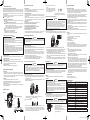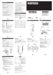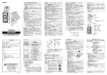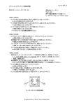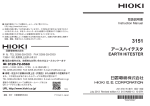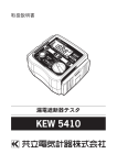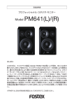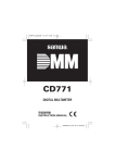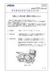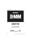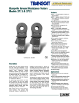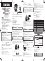
1
【3】各部の名称
入力端子
本体
L2
L1
KS3
L3
CCW: 逆相ランプ
モーター回転方向チェッカ
&三相検相器
本社=東京都千代田区外神田2−4−4・電波ビル
郵便番号=101-0021・電話=東京(03)3253−4871㈹
大阪営業所=大阪市浪速区恵美須西2−7−2
郵便番号 =556-0003・電話 =大阪(06)6631−7361㈹
SANWA ELECTRIC INSTRUMENT CO.,LTD.
Dempa Bldg., 4-4 Sotokanda2-Chome
Chiyoda-Ku,Tokyo,Japan
測定クリップ(CL-KS)
CW: 正相ランプ
バリア
電源ランプ
MOTOR ROTATION TESTER
& 3PHASE DETECTOR
取扱説明書
INSTRUCTION MANUAL
活線ランプ
電源スイッチ
測定コード(TL-KS) 全長約 0.7 m CAT. Ⅲ 500 V
【4】機能説明
01-1304 2040 6009
【1】安全に関する項目~ご使用の前に必ずお読みください。 ~
このたびは、モーター回転方向チェッカ&三相検相器 KS3 をお買い上げいた
だきありがとうございます。ご使用前にはこの取扱説明書をよくお読みいただき、
正しく安全にご使用ください。そして常にご覧いただけるように製品と一緒に大
切に保管してください。本文中の“ 警告”および“ 注意”の記載事項は、や
けどや感電などの事故防止のため、必ずお守りください。
1-1 警告マークなどの記号説明
本器および『取扱説明書』に使用されている記号と意味について
:安全に使用するための特に重要な事項を示します。
・警告文はやけどや感電などの人身事故を防止するためのものです。
・注意文は本器を壊すおそれのあるお取り扱いについての注意文です。
:警告、使用前に取扱説明書を参照の記号
:注意、感電の可能性
:二重絶縁または強化絶縁
CW:clockwise の略。時計回り(正相)
CCW:counterclockwise の略。反時計回り(逆相)
1-2 安全使用のための警告文
警 告
以下の項目は、やけどや感電などの人身事故を防止するためのものです。
本器をご使用する際には必ずお守りください。
1.AC 33 Vrms(46.7 Vpeak) または DC 70 V 以上の電圧は人体に危険なため
注意すること。
2.感電の危険を避けるため 500 V 以下の電路で使用すること。
3.本体や測定クリップまたは測定コードが傷んでいたり、壊れていたりする
場合は使用しないこと。
4.電池蓋を外した状態では使用しないこと。
5.電池交換を除く修理・改造は行わないこと。
6.始業前点検および年 1 回以上の点検は必ず行うこと。
7.本器の保護機能が損なわれることがあるので指定されている方法以外で使
用しないこと。
過電圧測定分類
過電圧測定分類(CAT. Ⅰ):コンセントから電源変圧器(トランス)等を経
由した機器内の二次側電路。
過電圧測定分類(CAT. Ⅱ):コンセントに接続する電源コード付き機器の一
次側電路。
過電圧測定分類(CAT. Ⅲ):直接分電盤から電気を取り込む機器の一次側お
よび分岐部からコンセントまでの電路。
過電圧測定分類(CAT. Ⅳ):引き込み線から分電盤までの電路。
4-1 電源スイッチ
電源の ON/OFF をします。測定後は電池の消耗を防ぐため必ず OFF にしてく
ださい。 ※ オートパワーオフ機能はありません。
4-2 活線ランプ
三相電路チェック時に対応した相が活線だと点灯します。消灯している相は欠相です。
※ 約 30 V 以上の入力で点灯します。また、モーター回転方向チェック時には入力電圧
は 30 V に満たないため点灯しません。
4-3 入力端子
測定コードの色を合わせて挿入します。
4-4 CW ランプ(時計回り・正相)
正相のときに点灯(緑)します。
4-5 CCW ランプ(反時計回り・逆相)
逆相のときに点灯(赤)
します。
4-6 電源ランプ(電池消耗警告)
電源が ON の時に点灯します。
また、内蔵電池が消耗し電池電圧が約 6.0 V 以下になると電源ランプは点灯しま
せん。点灯しない場合には早めに新しい電池と交換してください。
【5】測定方法
警 告
1.最大定格電圧を超えた測定をしないこと。
2.測定中は測定クリップのバリアより先を持たないこと。
5-1 始業前点検
感電事故を避けるため測定を始める前には必ず以下の項目を確認してください。
・外観チェック:落下などにより本体や測定クリップには異常がないか?測定
コードに断線やひび割れ等の異常はないか?
・既知の電線をクリップして活線ランプの点灯、検相を確認する。ランプが点灯
しない場合には測定コード、あるいは内部ヒューズの断線が考えられます。
※ヒューズ交換は修理依頼してください。(7-2 参照)
・電源ランプが点灯しない場合は新しい電池に交換する。
・本体や測定クリップまたは手が水で濡れた状態ではないか?
5-2 三相交流電源のチェック
① 3 本の測定コードを入力端子に接続する。
② 電源スイッチを ON にする。
③ 3 つの測定クリップを図のように三相交流電源の R-S-T に接続する。(2 つで
は正しい判別ができません。)
赤色の測定クリップを R に、白色の測定クリップを S に、青色の測定クリッ
プを T に接続します。
L2
5-3 モーター回転方向のチェック
① 3 本の測定コードを入力端子に接続する。
② 電源スイッチを ON にする。
③ 3 つの測定クリップを図のようにモーターの L1-L2-L3 に接続する。(2 つで
は正しい判別ができません。)
L1 L2 L3
Motor
L1
L2
L3
【8】仕 様
④ モーターの軸を規定以上の回転速度で回転させ方向を確認する。
正相
(時計回り)
は CWランプが緑色に点灯し、逆相
(反時計回り)は CCW ラン
プが赤色に点灯します。
※規定以上の回転速度とは 1 秒間に 2 回転以上(2 Hz 以上)です。また、モー
ターの極数により変化します。
※欠相がある場合はモーターの軸を正・逆どちらに回しても CW か CCW ランプのど
ちらか一方しか点灯しないまたはどちらも点灯しないので両方向で確認すること。
※正しい順番で接続すると逆回転をするモーターもあるのでモーターの仕様書
で確認してください。
【6】保守管理について
警 告
・ この項目は安全上重要です。本説明書をよく理解して管理を行ってください。
6-1 保守点検
始業前点検(項目 5-1)
を実行して異常がないことを確認してください。
異常がある場合はそのまま使用せず修理を依頼してください。
2-2 特 長
・IEC 61010-1 CAT. Ⅲ 500 V に準拠した安全設計。
・電線に接続する前にモーターの回転方向チェックが可能。
・三相電路の相順序および欠相のチェックが可能。
・明るい LED。
・本体の背面に磁石を装備してあり配電盤などに本製品を固定可能。
注 意
1.本体は揮発性溶剤に弱いため、シンナーやアルコールなどで拭かないこと。
2.本体は熱に弱いため、高熱を発するものの近くに置かないこと。
3.振動の多い場所や落下のおそれのある場所に保管しないこと。
4.直射日光下や高温、低温、多湿、結露のある場所での保管は避けること。
5.長期間使用しない場合は内蔵電池を必ず抜いておくこと。
L3
●出荷時の電池について
工場出荷時に組み込まれている電池はモニター用電池ですので電池寿命が新
品電池より短い場合があります。モニター用電池とは製品の機能や性能を
チェックするための電池のことです。
ランプ点灯表示: ランプ消灯表示: ④ 各相の欠相を確認する。
【7】アフターサービスについて
L3
上図の例は R 相、S 相はランプが点灯し、T 相は消灯なので T 相は欠相状態です。
※欠相がある場合でも CW または CCW ランプは点灯しますが、動作は規定で
きません。必ず活線ランプが 3 つ点灯した状態で判別してください。
− 1 −
①電池蓋の固定ネジ(1本)
をマイナスドライ
バーでまわす。
②電池蓋が浮き上がったらはずす。
③電 池ホルダ内の電池を極性に注意して新
品と交換する。
④電池蓋固定ネジを元どおりネジ止めする。
備考:この取扱説明書で使用するランプの点灯・消灯イラスト
L2
− 2 −
EMC 指令
付属品
三相 線間電圧 AC 75 ~ 500 V(正弦波・連続)
600 V
φ 5 × 20 ㎜ 0.5 A/500 V 遮 断容量 50 kA
40 ~ 400 Hz
2 Hz(2 回転 / 秒)~ 400 Hz の回転速度で判定
高度 2000 m以下、屋内使用、環境汚染度Ⅱ
0 ~ 40 ℃、80 %RH 以下(結露のないこと)
-10 ~ 50 ℃、80 %RH 以下(結露のないこと)
アルカリ 9 V 型乾電池 6LR61
(6LF22、1604 A)
×1
約 5 mA 待機状態 最大 約 10 mA
約 6.0 V 以下で電源ランプが消灯する。
約 60 時間
128(H ) × 72(W ) × 38(D) 約 210 g (電池含む)
IEC61010-1 CAT. Ⅲ500 V、IEC61557-1,7
IEC61010-2-030、IEC61010-031
IEC61326-1
測定クリップ(CL-KS)、測定コード
(TL-KS)
取扱説明書、キャリングポーチ(C-KS2)
ここに掲載した製品の仕様や外観は改良等の理由により、
予告なしに変更することがありますのでご了承ください。
保証書
ご氏名
ご住所
様
7-1 保証期間について
本製品の保証期間は、お買い上げの日より3 年間です。
ただし、日本国内で購入し日本国内でご使用いただく場合に限ります。
また、製品付属の電池、測定コード、測定クリップ等は保証対象外とさせていただきます。
7-2 修理について
1)修理依頼の前にもう一度内蔵電池の容量と電池装着時の極性をご確認ください。
− 3 −
型 名
製造 No.
KS3
この製品は厳密なる品質管理を経てお
届けするものです。
本保証書は所定項目をご記入の上保管
していただき、アフターサービスの際
ご提出ください。
※本保証書は再発行はいたしませんの
で大切に保管してください。
〒
6-4 内蔵電池交換
警 告
・ 感電事故を避けるため電池交換時には、電源を OFF にして測定クリップ
を測定対象から外してから作業を行うこと。
L1
使用電圧範囲
過負荷保護入力値
ヒューズ定格
電源周波数範囲
モーター回転
使用環境条件
使用温湿度範囲
保存温湿度範囲
電源
消費電流
電池消耗警告
連続使用時間
寸法・質量
安全規格
6-2 修理・点検
詳細については三和電気計器(株)・羽村工場サービス課までお問い合わせくだ
さい。(項目 7-2(4)「修理品の送り先」参照)
【2】用途と特長
2-1 用 途
本器は三相モーターの軸を手動で回すことによりモーターの回転方向の判別が
でき、また、三相電路の相順(正相、逆相)と欠相をチェックできる「モーター
回転方向チェッカです。
注 意
1.測定前にモーターに電圧がかかっていないか必ず確認すること。
2.モーター回転方向チェックで欠相がある場合どちらに回しても CW か CCW ランプ
の一方が点灯するまたはどちらも点灯しないので両方向に回して確認すること。
3.回転が遅い状態では正しい判定ができません。必ず軸が回転している状態で
判別すること。
(止まりかけの遅い回転では規定の回転速度を満たしません。
)
2)保証期間中の修理
・保証書の記載内容によって修理させていただきます。
3)保証期間経過後の修理
・ 修理によって本来の機能が維持できる場合、ご要望により有料で修理させていただきます。
・修理費用や輸送費用が製品価格より高くなる場合もありますので、事前にお問い合
わせください。
・本品の補修用性能部品の最低保有期間は、製造打切後 6 年間です。この補修用性能
部品保有期間を修理可能期間とさせていただきます。ただし購売部品の入手が製造
会社の製造中止等により不可能になった場合は、保有期間が短くなる場合もありま
すのでお含みおきください。
4)修理品の送り先
・製品の安全輸送のため、製品の 5 倍以上の容積の箱に入れ、十分なクッションを詰め
てお送りください。
・箱の表面に「修理品在中」と明記してください。
・輸送にかかる往復の送料は、お客様のご負担とさせていただきます。
[送り先]
三和電気計器株式会社・羽村工場サービス課
〒 205 − 8604 東京都羽村市神明台 4 − 7 − 15
TEL(042)554 − 0113 / FAX(042)555 − 9046
7-3 お問い合わせ
本社
:TEL(03)3253 − 4871 FAX(03)3251 − 7022
大阪営業所
:TEL(06)6631 − 7361 FAX(06)6644 − 3249
お客様計測相談室
:
0120 − 51 − 3930
受付時間 9:30 〜 12:00 13:00 〜 17:00
(土日祭日および弊社休日を除く)
ホームページ :http://www.sanwa-meter.co.jp
6-3 保管について
注 意
1.線間電圧が 30 V 以下の場合には活線ランプは点灯しません。
2.欠相がある場合でも CW か CCW ランプは点灯しますが、動作は規定でき
ません。活線ランプが 3 つ点灯した状態で判別してください。
3.単相 3 線では使用できません。
L1
⑤ 正相、逆相を確認する。
正相(時計回り)は CW ランプが
緑色に点灯し、逆相
(反時計回り)
は
CCWランプが赤色に点灯します。
上図の例は R、S、T が正相の状態です。
TEL
保証期間
ご購入日 年 月より 3 年間
本社=東京都千代田区外神田2−4−4・電波ビル
郵便番号=101-0021・電話=東京(03)3253−4871(代)
保証規定
保証期間中に正常な使用状態のもとで、万一故障が発生した場合には無償で修理いたします。
但し下記事項に該当する場合は無償修理の対象から除外いたします。
記
1.取扱説明書と異なる不適当な取扱いまたは使用による故障
2.当社サービスマン以外による不当な修理や改造に起因する故障
3.火災水害などの天災を始め故障の原因が本計器以外の事由による故障
4.電池の消耗による不動作
5.お買上げ後の輸送、移動、落下などによる故障および損傷
6.本保証書は日本国において有効です。
This warranty is valid only within Japan.
年 月 日
故障内容をご記入ください。
※無償の認定は当社において、行わせていただきます。
− 4 −
DRAWING No. KS3 01-1304 2040 6009
[1] SAFETY PRECAUTIONS
[4] DESCRIPTION OF FUNCTIONS
Before use, read the following safety precautions.
This instruction manual explains how to safely use your new KS3 motor rotation
tester & 3phase detector. Before use, please read this manual thoroughly. After
reading it, keep it together with the product so you can refer to it when necessary.
If this product is not used as specified in this manual, its protection function may
be compromised.
To avoid accidental burns or electric shock, always follow any instructions with
“ WARNING” or “ CAUTION” headings.
4-1 Power switch
Switches the power on and off. After measurement, be sure to set this switch to
OFF to prevent wasteful battery consumption.
Note: This instrument does not have the auto power-off
4-2 Open phase indicators
In the three-phase power line check, each indicator lights up when the
corresponding line is live. An extinguished indicator means that the phase of
the line is open.
Note: Each LED indicator lights at an input of about 30 V or more. These
indicators do not light during the motor rotation check because the input
voltages are less than 30 V.
4-3 Input jacks
Insert the measurement cords into the jacks of the same colors.
4-4 CW indicator (Clockwise = positive phase)
Lights (in green) when the phase is positive.
4-5 CCW indicator (Counterclockwise = negative phase)
Lights (in red) when the phase is negative.
4-6 Power ON indicator (Low battery warning)
Lights when the power is on.
It stops lighting when voltage of the built-in battery drops to 6.0 V or less. Replace
the battery with a new one as soon as possible if the indicator will not light.
1-1 Explanation of Warning Symbols
The meanings of the symbols used in this manual and on the products are
explained below.
: Very important instructions for safe use.
Warning messages are intended to prevent accidents to operating
personnel such as burn and electric shock.
Caution messages are intended to prevent damage to the instrument.
: Symbol requesting warning or reference to the instruction manual.
: Symbol requesting caution or risk of electric shock.
: Double insulation or reinforced insulation
CW: Stands for clockwise (positive phase).
CCW: Stands for counterclockwise (negative phase).
1-2 Warning Instructions for Safe Use
To avoid physical injury such as burns or electric shock, be sure to observe the
following instructions when using this instrument.
1. Pay special attention when measuring voltages of AC 33 Vrms (46.7 V
peak) or DC 70 V or more to avoid injury.
2.Never use the instrument on lines that exceed 500 V to avoid the risk of
electric shock.
3.Do not use the instrument if the main unit, measurement clip, or
measurement cord is damaged or broken.
4. Do not use the instrument with the battery compartment cover removed.
5. Do not attempt to repair or modify the instrument except to replace the battery.
6. Be sure to check the instrument before each use and inspect it at least once a year.
7.To avoid compromising the protection function of this instrument, do not
use it in any way other than instructed in this manual.
Measurement category (overvoltage category)
Equipment of CAT I:
Secondary cable runs from a power supply transformer connected to a wall socket.
Equipment of CAT II:
Primary cable runs of power-consuming equipments from a wall socket.
Equipment of CAT III:
Primary cable runs of equipments directly connected to a distribution board and
cable runs from a distribution board to wall sockets.
Equipment of CAT IV:
Cable runs from an incoming line to a distribution board.
[2] APPLICATION AND FEATURES
2-1 Application
This instrument is a motor rotation tester & 3phase detector that allows you to
determine the rotation direction of a three-phase motor by turning the motor
shaft manually, as well as to check the phase sequence (positive, negative)
and open phase condition of three-phase lines.
2-2 Features
•Safety design that complies with IEC61010-1 CAT. III 500 V.
•Motor rotation direction testable before connection of the power supply.
•Phase sequence and open phase checking of three-phase lines.
•Bright LED indicators.
•Magnets on the back of the main unit allow it to be fixed on a distribution board
and other metallic objects.
WARNING
Motor
CCW
nagative-phase
indicator
Open phase indicators
Measurement Clip (CL-KS)
CW positive-phase
indicator
Barrier
Power On LED
Measurement cord (TL-KS)
Overall length approx. 0.7 m (CAT III 500 V)
− 1 −
L2
L3
(4) Turn the motor shaft at a speed higher than the specified rotation speed.
When the phase is positive (clockwise), the CW indicator lights green. When
the phase is negative (counterclockwise), the CCW indicator lights red.
* The specified rotation speed refers to 2 rotations or more per sec. This
figure is variable depending on the number of motor poles.
* If there is an open phase, turning the motor shaft in either direction lights
either or none of the CW and CCW indicators. Be sure to check by turning it
in both directions.
* Certain motors may rotate in the opposite direction when they are connected in
the correct sequence. Please check the specifications document of your motor.
5-2 Checking the three-phase power lines
[6] MAINTENANCE
WARNING
CAUTION
1. The open phase indicators do not light if any of the line voltages is less
than 30 V.
2. The CW or CCW indicator lights up even when there is an open phase,
but the operation is not guaranteed. Be always sure to check the phase
sequence while all of the open phase indicators are ON.
3. This instrument cannot be used with three single-phase lines.
(1) Insert the three measurement cords into the input jacks.
(2) Set the Power switch to ON.
(3) Connect the three measurement clips to R-S-T of the three-phase AC power
supply as shown below (correct measurement is impossible if only two of
them are connected)/
Connect the red measurement clip to R, the white measurement clip to S and
the blue measurement clip to T.
L2
L3
Note: Illustrations of ON/OFF status of the indicators in this manual
LED ON indication LED OFF indication
(4) Check the open phase.
L1
Power switch
L1
5-1 Pre-operational Check
Perform pre-operational check for safety.
•Check the external appearance. Check that there is no abnormality with the
main unit and measurement clips. Check that there is no abnormality with the
cord such as disconnection or cracking.
•Check the lighting of the open phase indicators and the functioning of the
phase detection by clipping cables with known voltages and phases.
If one or more indicator(s) do not light, the measurement cord(s) may be
disconnected or the built-in fuse may be blown.
Note: For the fuse replacement, please contact us (see section 7-2).
•If the Power ON indicator will not light, replace the battery with a new one.
•Make sure your hands and the measurement clips are not wet.
Input jacks
L3
(1) Insert the three measurement cords into the input jacks.
(2) Set the Power switch to ON.
(3) Connect the three measurement clips to L1-L2-L3 of the motor as shown
below (correct measurement is impossible if only two of them are connected).
L1 L2 L3
[3] NAMES OF PARTS
L2
CAUTION
1. Before measurement, make sure that no voltage is applied to the motor.
2. If an open phase is detected in the motor rotation direction check, turning
the motor shaft in either direction lights either or none of the CW and
CCW indicators. Be sure to check by turning it in both directions.
3. Correct judgment is impossible if the turning speed is low. Be sure to
check by turning the motor shaft at a certain speed (the specified rotation
speed cannot be reached if it is half stopped or turned at a low speed).
1. Do not perform measurement of a voltage exceeding the maximum rated voltage.
2.During measurement, do not hold the measurement clip at any point
beyond the barrier.
L1
L1
5-3 Checking the motor rotation direction
[5] MEASUREMENT PROCEDURES
WARNING
Main Unit
(5) Check whether the phase is positive or
negative.
When the phase is positive (clockwise),
the CW indicator lights green. When the
phase is negative (counterclockwise),
the CCW indicator lights red.
The example above shows the status in which the phase of R, S and T is positive.
L2
L3
In the example above, the indicators of the R- and S-phases are ON and the
indicator of the T-phase is OFF, which means that the phase of T is an open phase.
* The CW or CCW indicator lights up even when there is an open phase, but
the operation is not guaranteed. Be always sure to check the phase
sequence while all of the open phase indicators are ON.
− 2 −
• The section is very important for safety. Read and understand the
following instructions fully and maintain your instrument properly.
6-1 Maintenance and Inspection
Before use, check the instrument as specified (see section 5-1) to confirm that
there is no abnormality. If anything is abnormal, do not use the instrument and
return it to your authorized Sanwa agent or distributor for repair.
6-2 Repair
For details, please contact your authorized Sanwa agent or distributor.
6-3 Storage
CAUTION
1.The panel and case are not resistant to volatile solvent and must not be
cleaned with thinner or alcohol.
2. The panel and case are not resistant to heat. Do not place the instrument
near heat-generating devices (such as a soldering iron).
3. Do not store the instrument anywhere it may be subject to vibrations or could fall.
4. When storing the instrument, avoid hot, cold or humid locations, locations
exposed to direct sunlight, or locations where condensation is anticipated.
5.When the instrument is not going to be used for an extended time, be
sure to remove the batteries.
6-4 Battery Replacement
●The battery loaded at the factory is a monitor battery, so their service life may
be shorter than that of a brand-new battery. A monitor battery is a type of
battery used to check the functions and performance of a product.
WARNING
• To avoid electric shock when replacing the batteries, first disconnect the
measurement clips from the object to be measured, and turn off the power.
①Remove the fixing screw (x 1) from the
battery compartment cover.
②S lide the battery compartment cover
downward to remove it.
③Replace the battery with new ones.
④Place the battery compartment cover and
tighten the fixing screw.
− 3 −
[7] AFTER-SALE SERVICE
7-1 Warranty and Provision
Sanwa offers comprehensive warranty services to its end-users and to its
product resellers. Under Sanwa’s general warranty policy, each instrument is
warranted to be free from defects in workmanship or material under normal use
for the period of one (1) year from the date of purchase.
This warranty policy is valid within the country of purchase only, and applied
only to the product purchased from Sanwa authorized agent or distributor.
Sanwa reserves the right to inspect all warranty claims to determine the extent
to which the warranty policy shall apply.
This warranty shall not apply to the battery, measurement cable and
measurement clips provided with the product, which have been subject to one
of the following causes:
1.A failure due to improper handling or use that deviates from the instruction manual.
2.A failure due to inadequate repair or modification by people other than Sanwa
service personnel.
3.A failure due to causes not attributable to this product such as fire, flood and
other natural disaster.
4.Non-operation due to a discharged battery.
5.A failure or damage due to transportation, relocation or dropping after the purchase.
7-2 Repair
Customers are asked to provide the following information when requesting
services:
1.Customer name, address, and contact information
2.Description of problem
3.Description of product configuration
4.Model Number
5.Product Serial Number
6.Proof of Date-of-Purchase
7.Where you purchased the product
Please contact Sanwa authorized agent / distributor / service provider, listed in
our website, in your country with above information. An instrument sent to Sanwa
/ agent / distributor without those information will be returned to the customer.
Note:
1)Prior to requesting repair, please check the following:
• Capacity and installation polarity of the built-in batteries.
• Continuity of the test leads.
2)Repair during the warranty period:
The failed instrument will be repaired in accordance with the conditions
stipulated in “7-1 Warranty and Provision”.
3)Repair after the warranty period has expired:
In some cases, repair and transportation cost may become higher than the
price of the product. Please contact Sanwa authorized agent / service
provider in advance. The minimum retention period of service functional
parts is 6 years after the discontinuation of manufacture. This retention
period is the repair warranty period. Please note, however, if such functional
parts become unavailable for reasons of discontinuation of manufacture,
etc., the retention period may become shorter accordingly.
4)Precautions when sending the product to be repaired
To ensure the safety of the product during transportation, place the product
in a box that is larger than the product 5 times or more in volume and fill
cushion materials fully and then clearly mark “Repair Product Enclosed” on
the box surface. The cost of sending and returning the product shall be
borne by the customer.
7-3 SANWA Website
http://www.sanwa-meter.co.jp
E-mail: [email protected]
[8] SPECIFICATIONS
Operating voltage range
Overload protection input
Fuse rating
Power frequency range
Motor rotation direction
Operation environment
Operating temperature/ humidity
ranges
Storage temperature/ humidity
ranges
Power supply
Power consumption
Low battery indication
Continuous operation duration
Dimensions and mass
Safety standards
EMC directive
Accessories
Three-phase, line voltage 75 to 500 V AC (sine wave,
continuous).
600 V
φ5 x 20 mm, 0.5 A/500 V Breaking capacity 50 kA
40 to 400 Hz.
Determined at rotation speeds from 2 Hz (2 rotations/
sec.) to 400 Hz.
Altitude 2000 m or less, indoor use, environmental
pollution degree II.
0 to 40 °C, 80 % RH or less (without condensation).
-10 to 50 °C, 80 % RH or less (without condensation).
Alkaline 9 V battery 6LR61 (6LF22, 1604 A) ×1
Approx. 5 mA (standby state), approx. 10 mA (MAX)
Power ON indicator stops lighting at approx. 6.0 V or
less.
Approx. 60 hours
128 (H) x 72 (W) x 38 (D) mm, approx. 210 g
(including battery).
IEC61010-1, CAT. III 500 V, IEC61557-1,7,
IEC61010-2-030, IEC61010-031.
IEC61326-1.
Measurement clips (CL-KS), measurement cords
(TL-KS), instruction manual, carrying pouch (C-KS2).
Specifications and external appearance of the product described above may
be revised or modified without prior notice.
− 4 −
DRAWING No. KS3 01-1304 2040 6009