1
User's
Manual
PK200
CURRENT-TO-PNEUMATIC
CONVERTER
[Style:S2]
IM 21B03D01-01E
IM 21B03D01-01E
12th Edition
CONTENTS
CONTENTS
INTRODUCTION .............................................................................................. iii
1.
HANDLING PRECAUTIONS ......................................................................... 1-1
1.1
1.2
1.3
1.4
1.5
Checking the Model Suffix Code and Specifications .......................... 1-1
Transportation Precautions ................................................................. 1-1
Storage Precautions ............................................................................ 1-2
Precautions for Installation Area ......................................................... 1-2
Installation of Intrinsically Safe Type .................................................. 1-2
1.5.1 CSA Intrinsically Safe Type ......................................................... 1-2
1.5.2 TIIS Intrinsically Safe Type .......................................................... 1-3
1.6 Installation of Flameproof Type .......................................................... 1-3
1.6.1 TIIS Flameproof Type .................................................................. 1-3
1.6.2 FM Explosionproof Type .............................................................. 1-4
1.7 EMC Conformity Standard .................................................................. 1-4
2.
OVERVIEW .................................................................................................... 2-1
2.1
2.2
2.3
2.4
2.5
2.6
3.
INSTALLATION ............................................................................................. 3-1
3.1
3.2
4.
Functional Description ......................................................................... 2-1
Standard Specifications ...................................................................... 2-1
Model and Suffix Codes ...................................................................... 2-2
Options ................................................................................................ 2-2
External Dimensions ........................................................................... 2-3
Part Names ......................................................................................... 2-4
Overview ............................................................................................. 3-1
Installation ........................................................................................... 3-1
3.2.1 Pipe Mounting .............................................................................. 3-1
3.2.2 Wall Mounting ............................................................................... 3-1
WIRING AND PIPING ................................................................................... 4-1
4.1
Piping .................................................................................................. 4-1
4.1.1 Supply Air ..................................................................................... 4-1
4.1.2 Air Supply Piping .......................................................................... 4-1
4.1.3 Output Piping ................................................................................ 4-1
4.2 General-Use and Flameproof Type Wiring ......................................... 4-1
4.2.1 Cable Selection ............................................................................ 4-1
4.2.2 Wiring ........................................................................................... 4-2
4.2.3 Grounding ..................................................................................... 4-4
4.3 Intrinsically Safe Type Wiring ............................................................. 4-4
5.
OPERATION .................................................................................................. 5-1
5.1
5.2
5.3
5.4
5.5
Auto/Manual (A/M) Transfer Mechanism ............................................ 5-1
Zero Point Adjustment ........................................................................ 5-1
Calibration ........................................................................................... 5-2
Range Adjustment ............................................................................... 5-4
4 to 20mA/10 to 50mA Selection ........................................................ 5-4
FD No. IM 21B03D01-01E
12th Edition: Aug. 2012 (KP)
All Rights Reserved, Copyright © 1992, Yokogawa Electric Corporation
i
IM 21B03D01-01E
CONTENTS
6.
MAINTENANCE ............................................................................................. 6-1
6.1
6.2
Overview ............................................................................................. 6-1
Periodic Inspection .............................................................................. 6-1
6.2.1 Cleaning the Restrictor ................................................................. 6-1
6.3 Parts Replacement .............................................................................. 6-1
6.3.1 Replacing the Screen Filter .......................................................... 6-1
6.3.2 Replacing the Controller Relay .................................................... 6-2
6.3.3 Replacing the Amplifier Assembly ............................................... 6-2
7.
TROUBLESHOOTING ................................................................................... 7-1
7.1
7.2
7.3
Overview ............................................................................................. 7-1
Operation Principle .............................................................................. 7-1
Troubleshooting Flow .......................................................................... 7-2
Appendix A. AIR SUPPLY SYSTEM................................................................ A-1
INSTALLATION AND OPERATING PRECAUTIONS FOR TIIS INTRINSICALLY
SAFE EQUIPMENT ............................................................................. Ex-A03E
INSTALLATION AND OPERATING PRECAUTIONS FOR TIIS FLAMEPROOF
EQUIPMENT ........................................................................................ Ex-B03E
Customer Maintenance Parts List
Model PK200 Current-to-Pneumatic Converter .............. CMPL 21B03D01-01E
Revision Record
ii
IM 21B03D01-01E
INTRODUCTION
INTRODUCTION
Thank you for purchasing the Current-to-Pneumatic
Converter.
• Yokogawa will not be liable for malfunctions or
damage resulting from any modification made to
this instrument by the customer.
The Current-to-Pneumatic Converter is correctly
calibrated at the factory before shipment. To ensure
correct and efficient use of the instrument, please read
this manual thoroughly and fully understand how to
operate the instrument before operating it.
• For the intrinsically safe equipment and
explosionproof equipment, in case the instrument is
not restored to its original condition after any repair
or modification undertaken by the customer,
intrinsically safe construction or explosionproof
construction is damaged and may cause dangerous
condition. Please contact Yokogawa for any repair
or modification required to the instrument.
■
Regarding This Manual
• This manual should be passed on to the end user.
• The contents of this manual are subject to change
without prior notice.
• All rights reserved. No part of this manual may be
reproduced in any form without Yokogawa’s written
permission.
• Yokogawa makes no warranty of any kind with
regard to this manual, including, but not limited to,
implied warranty of merchantability and fitness for a
particular purpose.
• If any question arises or errors are found, or if any
information is missing from this manual, please
inform the nearest Yokogawa sales office.
• The specifications covered by this manual are
limited to those for the standard type under the
specified model number break-down and do not
cover custom-made instrument.
• Please note that changes in the specifications,
construction, or component parts of the instrument
may not immediately be reflected in this manual at
the time of change, provided that postponement of
revisions will not cause difficulty to the user from a
functional or performance standpoint.
• The following safety symbol marks are used in this
Manual:
WARNING
Indicates a potentially hazardous situation which,
if not avoided, could result in death or serious
injury.
CAUTION
Indicates a potentially hazardous situation which,
if not avoided, may result in minor or moderate
injury. It may also be used to alert against
unsafe practices.
IMPORTANT
Indicates that operating the hardware or software
in this manner may damage it or lead to system
failure.
■ Safety Precautions
• For the protection and safety of the operator and the
instrument or the system including the instrument,
please be sure to follow the instructions on safety
described in this manual when handling this instrument. In case the instrument is handled in contradiction to these instructions, Yokogawa does not
guarantee safety.
NOTE
Draws attention to information essential for
understanding the operation and features.
iii
IM 21B03D01-01E
INTRODUCTION
WARRANTY
• The warranty shall cover the period noted on the
quotation presented to the purchaser at the time of
purchase. Problems occurred during the warranty
period shall basically be repaired free of charge.
• In case of problems, the customer should contact the
Yokogawa representative from which the instrument
was purchased, or the nearest Yokogawa office.
• If a problem arises with this instrument, please
inform us of the nature of the problem and the
circumstances under which it developed, including
the model specification and serial number. Any
diagrams, data and other information you can
include in your communication will also be helpful.
• Responsible party for repair cost for the problems
shall be determined by Yokogawa based on our
investigation.
● The Purchaser shall bear the responsibility for
repair costs, even during the warranty period, if
the malfunction is due to:
• Improper and/or inadequate maintenance by the
Purchaser.
• Failure or damage due to improper handling, use or
storage which is out of design conditions.
• Use of the product in question in a location not
conforming to the standards specified by the
Yokogawa, or due to improper maintenance of the
installation location.
• Failure or damage due to modification or repair by
the party except Yokogawa or who is requested by
Yokogawa.
• Malfunction or damage from improper relocation of
the product in question after delivery.
• Reason of force majeure such as fires, earthquakes,
storms/floods, thunder/lightening, or other natural
disasters, or disturbances, riots, warfare, or radioactive contamination.
iv
IM 21B03D01-01E
1. HANDLING PRECAUTIONS
1.
HANDLING PRECAUTIONS
IMPORTANT
For installation, wiring and maintenance in
hazadous areas, please follow 1.5 Installation of
Intrinsically Safe Type, 1.6 Installation of Flameproof Type and “Installation and Operating
Precautions for TIIS Flameproof Equipment” at
the end of this manual
The PK200 current-to-pneumatic converter is fully
factory inspected before shipment. When the instrument is delivered, visually check the instrument and
accessories to ensure that they are not damaged. This
chapter describes the handling precautions, read them
carefully before using the instrument.
Figure 1.2 Data Plate for CSA Intrinsically Safe Type
For items other than those described in this chapter, see
the relevant items.
If you wish to make inquiry, contact the distributor
where you purchased the instrument or the nearest
YOKOGAWA service station.
Figure 1.3 Data Plate for FM Explosionproof Type
1.1 Checking the Model Suffix
Code and Specifications
The data plate on the side face of the instrument base
shows the model suffix code and specifications. With
reference to the model suffix code and specifications in
section 2.3, confirm that the instrument is as specified
by the order.
1.2 Transportation Precautions
To prevent damage occurring during transportation,
transport the converter in the original shipping container (box) with all packing items and equipment in its
proper position.
For inquiry, inform us of the model suffix code and
instrument serial number.
Figure 1.1 Data Plate for General-Use Type
1-1
IM 21B03D01-01E
1. HANDLING PRECAUTIONS
1.3 Storage Precautions
(1) Select a storage place :
• Which is protected from rain and water.
• Which is free from vibration and impact.
• Whose temperature and humidity are as specified
below. Room temperature and humidity (approx.
25°C and 65%) are more recommendable.
Temperature: -10 to 60°C
Humidity: Less than 80%
(2) Store the converter in the packing condition of
shipment from YOKOGAWA whenever possible.
1.5 Installation of Intrinsically
Safe Type
1.5.1 CSA Intrinsically Safe Type
[Intrinsically Safe]
Hazardous Location
Class I, II, III, Division 1,
Groups A, B, C, D, E, F, G
Safety Barrier
+
+
+
+
–
–
–
–
[Nonincendive]
To use the converter stably for a long time, determine
an installation place, taking into account the following.
Hazardous Location
Class I, II, III, Division 2,
Groups A, B, C, D, E, F, G
Class III, Division 1.
(1) Ambient Temperature
Avoid installing the instrument in a place subject to a
large temperature gradient and variations. If the
instrument is subject to plant-generated heat radiation,
take measures such as provision of heat protection and
good ventilation.
(3) Magnetic Field
Please contact us in the case this instrument is installed
the strong Magnetic Field.
General
Purpose
Equipment
PK200
Current-topneumatic Converter
1.4 Precautions for Installation
Area
(2) Atmospheric Conditions
Avoid installing the converter in corrosive atmosphere.
Should it be used in corrosive atmosphere, make
provision for maintaining good ventilation.
Non-hazardous Location
Non-hazardous Location
General
Purpose
Equipment
+
+
–
–
PK200
Current-topneumatic Converter
Note: Not use safety Barrier
F0105.EPS
Figure 1.4 Installation of CSA Intrinsically Safe Type
1. PK200 current to pneumatic converter is
applicable for use in hazardous locations:
• Intrinsically Safe for Class I, Division 1, Groups A,
B, C & D, Class II, Division 1, Groups E, F & G
and Class III, Division 1 Hazardous Locations.
• Nonincendive for Class I, Division 2, Groups A, B,
C & D, Class II, Division 2, Groups F & G, and
Class III, Division 1 Hazardous Locations.
• Outdoor Hazardous Locations, Encl Type 4X.
• Temperature Class: T4
• Ambient Temperature: -40 to 60°C
2. Entity Parameters
• Intrinsically safe apparatus parameters
Vmax = 30V
Imax = 165mA
Pmax = 0.9W
Ci = 2nF
Li = 730µ H
• Associated apparatus parameters (CSA Certified
Barriers)
Voc ≤ 30V
Isc ≤ 165mA
Pmax ≤ 0.9W
1-2
IM 21B03D01-01E
1. HANDLING PRECAUTIONS
3. Installation
• Control equipment connected to barrier must not use
or generate more than 250 Vrms or Vdc.
• The safety barrier must be CSA certified.
• Associated apparatus manufacturer’s installation
drawing must be followed when installing this
apparatus.
• The maximum power delivered from the barrier
must not exceed 0.9 W.
• Note a warning label worded “SUBSTITUTION OF
COMPONENTS MAY IMPAIR INTRINSIC
SAFETY” and “INSTALL IN ACCORDANCE
WITH DOC. NO. ICS006-A12 P.1 AND 2”.
1.5.2 TIIS Intrinsically Safe Type
The model PK200/JS3 current-to-pneumatic converters,
which have obtained certification according to technical criteria for explosion-protected construction of
electric machinery and equipment (Standards Notification No.556 from the Japanese Ministry of Labor)
conforming to IEC standards, is designed for hazardous
areas where explosive gases and/or inflammable vapors
may be present. (This allows installation in Division 0 ,
1 and 2 areas)
To preserve the safety of flameproof equipment
requires great care during mounting, wiring, and
piping. Safety requirements also place restrictions on
maintenance and repair activities. Users absolutely
must read the following instructions and “Installation
and Operating Precautions for TIIS Intrinsically Safe
Equipment (EX - A03E)” at the end of this manual.
1. Installation
The PK200 Current-to-Pneumatic Converter should be
used in connection with the certified safety barrier as
shown below. All wiring shall comply with local
installation requirements.
[Installation Diagram]
Hazardous Area
Non-hazardous Area
+
+
+
–
–
–
PK200 Current-to-pneumatic
Converter
Safety barrier
F0107.EPS
2. Temperature
Install the PK200, So that any part of the instrument
that may exposed to the inflammable gas or vapor
would not exceed the temperature 60°C
3. Safety Barrier
Use the certified safety barrier that satisfies the
following requirements.
•
Safety Ratings
Maximum output voltage: 28V or less
Maximum output current: 94.3mA or less
Maximum output power: 0.66W or less
• Protection type and group
Protection type: ia Group: IIC
• Allowable inductance and capacitance
Maximum_external inductance: More than the
external wiring inductance
Maximum_external capacitance: More than the sum
of the external wiring capacitance and 39nF
Table 1.1 Recommended Safety Barrier
Contact each supplier for the details of the barrier.
Supplier
Type
Model
MTL
Isolated type
MTL5046
P+F
Isolated type
KFD2-SCD-Ex1.LK*
T0101.EPS
* To connect this barrier with PK200 converter, for
the connection between the barrier and the controller, use the terminal #7 and #9 of the barrier.
1.6 Installation of Flameproof
Type
1.6.1 TIIS Flameproof Type
The model PK200/JF3 current-to-pneumatic converters,
which have obtained certification according to technical criteria for explosion-protected construction of
electric machinery and equipment (Standards Notification No.556 from the Japanese Ministry of Labor)
conforming to IEC standards, is designed for hazardous
areas where explosive gases and/or inflammable vapors
may be present. (This allows installation in Division 1
and 2 areas)
To preserve the safety of flameproof equipment
requires great care during mounting, wiring, and
piping. Safety requirements also place restrictions on
maintenance and repair activities. Users absolutely
must read “Installation and Operating Precautions for
TIIS Flameproof Equipment (EX - B03E)” at the end
of this manual.
1-3
IM 21B03D01-01E
1. HANDLING PRECAUTIONS
1.6.2 FM Explosionproof Type
1.7 EMC Conformity Standard
Following items are described in the instruction
documents of this instrument to ensure certified
explosionproof properties.
EN61326-1 Class A, Table 2
(For use in industrial locations)
1. PK200 Current to Pneumatic Converter is
applicable for use in hazardous areas;
* Explosionproof for Class I, Division 1, Groups B, C
and D.
* Dust ignitionproof for Class I/II, Division 1, Groups
E, F and G.
* Outdoor hazardous locations, NEMA 4X.
CAUTION
To meet EMC regulations, Yokogawa recommends that customers run signal wiring through
metal conduits or use shielded twisted-pair
cabling when installing this instrument in a plant.
2. Wiring
* All wiring shall comply with National Electrical
Code ANSI/NEPA70 and Local Electrical Codes.
* When installed in Division 1, “FACTORY
SEALED, CONDUIT SEAL NOT REQUIRED”.
However, in case of installing a sealing fitting
(option) for waterproof or other purposes, see
4.2.2(6).
CAUTION
This instrument is a Class A product, and it is
designed for use in the industrial environment.
Please use this instrument in the industrial
environment only.
3. Operation
* WARNING: OPEN CIRCUIT BEFORE REMOVING COVER.
FACTORY SEALED, CONDUIT
SEAL NOT REQUIRED.
INSTALL IN ACCORDANCE
WITH THE INSTRUCTION
MANUAL IM 21B3D1-01E
* Take care not to generate mechanical spark when
access to the instrument and peripheral devices in
hazardous location.
4. Maintenance and Repair
* The instrument modification or parts replacement by
other than authorized representative of Yokogawa
Electric Corporation is prohibited and will void
Factory Mutual Explosionproof Certification.
1-4
IM 21B03D01-01E
2. OVERVIEW
2.
OVERVIEW
2.1 Functional Description
I/O Action:
The PK200 current-to-pneumatic converter is a signal
converter that receives an electronic controller or DCS
control signal and converts it into a pneumatic pressure
signal.
2.2 Standard Specifications
Materials:
Case: Aluminum die-cast
Paint: Polyurethane resin-baked finish
Paint color: Deep-sea moss-green
(Munsell 0.6GY3.1/2.0 or equivalent)
Pressure Gauge Case: Stainless steel
JIS SUS304
Input Signals: 4 to 20mA DC or 10 to 50mA DC
Input Resistance: PK200 is not a constant resistor.
Equivalent circuit of PK200 is shown in Fig. 2.1
Constant
Voltage
Circuit
Input Signal
4 to 20mA DC
5V DC
(8V DC for CENELEC
Intrinsically safe type and
TIIS Intrinsically safe type.)
50Ω MAX
F0201.EPS
Fig. 2.1 Equivalent Circuit
Operating Voltage:
Input Signal
Min.
Max.
4 to 20mA (except /JS3)
5.2V (at 4mA)
6.0V (at 20mA)
4 to 20mA (for /JS3)
8.2V (at 4mA)
9.0V (at 20mA)
10 to 50mA
5.35V (at 10mA)
6.75V (at 50mA)
Output pressure increases as input
increases.
Manual Operation: Available using auto/manual (A/M)
transfer switch (Optional)
Zero Point Adjusting Range: Within 0 to ±10% of span
Span Adjusting Range: Within 100 to 125% of span
Air Consumption: 4Nl/min maximum (for a supply air
pressure of 140kPa)
Max. Air Delivery: 110Nl/min maximum (for a supply
air pressure of 140kPa)
Minimum Load Capacity:
1m copper tube with 4mm I.D. +20cc
Ambient Temperature:
-40 to 80°C (for general use)
-20 to 60°C (TIIS Explosionproof ,
TIIS Intrinsically safe type)
-40 to 60°C (for FM Explosionproof,
CSA Intrinsically safe type)
Water Proof Construction:
IEC IP54
NEMA type 4X
Intrinsically Safe Construction:
CSA Intrinsically Safe (/CS1) : Intrinsically Safe for
Class I, Division 1, Groups A, B, C
& D Class II, Division 1, Groups E, F
& G and Class III, Division 1
Hazardous Locations.
Nonincendive for Class I, Division 2,
Groups A, B, C & D, Class II,
Division 2, Groups F & G, and Class
III, Division 1 Hazardous Locations.
Outdoor Hazardous Locations, Encl
Type 4X.
Temperature Class: T4
T0200.EPS
Output Signals:
Standard Output
Output Signal
Doubled Output
Output Signal
Pressure Gauge
Scale
Recomended
Supply Air
Pressure *1
Supply Air
Pressure Gauge
Scale *1
0 to 200kPa
40 to 200kPa
0 to 400kPa
130 to 150kPa
0 to 200kPa
230 to 260kPa
0 to 400kPa
0 to 2kgf/cm2
0.4 to 2.0 kgf/cm2
0 to 4kgf/cm2
1.3 to 1.5kgf/cm2
0 to 2kgf/cm2
2.3 to 2.6kgf/cm2
0 to 4kgf/cm2
1.3 to 1.5bar
0 to 2bar
Output Signal
Pressure Gauge
Scale
Pa calibration
20 to 100kPa
kgf/cm2 calibration
0.2 to 1.0 kgf/cm2
Bar calibration
0.2 to 1.0bar
0 to 2bar
0.4 to 2.0bar
0 to 4bar
P calibration
3 to 15psi
0 to 30psi
6 to 30psi
0 to 60psi
3 to 27psi
2.3 to 2.6bar
0 to 4bar
19 to 22psi
0 to 30psi
33 to 37psi
0 to 60psi
*1: Set supply air pressure in the range given in the upper column for standard output and in the range given in the lower column for
multiplied pressure output.
T0201.EPS
2-1
IM 21B03D01-01E
2. OVERVIEW
2.4 Options
TIIS Intrinsically Safe (/JS3):
Intrinsically Safe Ex ia IIC T4
Certificate: TC18266
Explosionproof Construction:
TIIS Explosionproof (/JF3): Flameproof Exd II
B+H2 T6X
FM Explosionproof (/FF1): Explosionproof for Class
I, Division 1, Groups B, C and D.
Dust ignitionproof for Class II/III,
Division 1, Groups E, F and G.
Temperature Class: T6.
Outdoor hazardous locations, NEMA
4X.
Dustproof Construction: IEC IP54
Connections:
Air Connection: Rc1/4 or 1/4NPT female
Electrical Connection: G1/2, G3/4 female or
1/2NPT, 3/4NPT female
Mounting:
Vertical or horizontal 50mm (2INCH) pipe mounting
Wall mounting
Mass (weight): 2.8kg (6.1lb)
Accuracy:
±0.5% of span
Linearity:
±0.2% of span
Hysteresis:
0.2% of span
Repeatability: 0.1% of span
• Option Code/JF3: JIS Flameproof
TIIS flameproof Exd II B+H2 T6X
• Option Code/G11: Packing adapter for TIIS Flameproof
Electrical connection: G1/2 female, Applicable cable
O.D.: 8 to 12mm
• Option Code/G21: Packing adapter for TIIS Flameproof
Electrical connection: G3/4 female, Applicable cable
O.D.: 10 to 16mm
• Option Code/FF1: FM Explosionproof
• Option Code/JS3: TIIS Intrinsically Safe
Applicable only with input signal code-A.
• Option Code/CS1: CSA Intrinsically Safe
• Option Code/SCF-: Special Color Finished on
converter cover
Allows the paint color of only a converter cover to
be selectable by specifying the color in the specification item with reference to GS22D1F1.
• Option Code/X1: Epoxy Paint
Epoxy resin-baked coating.
Not applicable for special color finished.
2.3 Model and Suffix Codes
Model
Suffix Code
Description
PK200
Input Signal -A
-C
Output Signal
Connections
Option
4 to 20mA DC
4 to 20mA/10 to 50mA DC selection type
1
2
3
4
5
6
7
8
9
Output signal Pa calibration
Output signal Pa calibration
Output signal kgf/cm2 calibration
Output signal kgf/cm2 calibration
Output signal bar calibration
Output signal bar calibration
Output signal P calibration
Output signal P calibration
Output signal P calibration
1
2
3
4
20 to 100kPa
40 to 200kPa
0.2 to 1.0 kgf/cm2
0.4 to 2.0 kgf/cm2
0.2 to 1.0bar
0.4 to 2.0bar
3 to 15psi
6 to 30psi
6 to 27psi
scale 0 to 200kPa
scale 0 to 400kPa
scale 0 to 2kgf/cm2
scale 0 to 4kgf/cm2
scale 0 to 2bar
scale 0 to 4bar
scale 0 to 30Psi
scale 0 to 60Psi
scale 0 to 60Psi
Air connection: Rc 1/4, Electrical connection: G1/2 female
Air connection: Rc 1/4, Electrical connection: G3/4 female
Air connection: 1/4 NPT female, Electrical connection: 1/2NPT female
Air connection: 1/4 NPT female, Electrical connection: 3/4NPT female
/
See section 2.4.
T0202.EPS
2-2
IM 21B03D01-01E
2. OVERVIEW
• Option Code/L: Lightning Protector
Installed in the terminal box to protect internal
circuitry from high voltage surges such as those
caused by lightning induced.
• Option Code/AM: AUTO/MANUAL Switch
Mounted on front of housing, in manual mode,
output signal is varied by adjusting the external
supply pressure regulator.
• Option Code/SS: Stainless Steal Screw and Bracket
Screw and bracket, both are made of stainless steal.
• Option Code/RA: Reverse Action
Increasing of input signal to make output pressure
decrease.
• Option Code/GW: Double Scale Pressure Gauge
Double scales are kPa and kgf/cm2.
2.5 External Dimensions
Unit: mm
165.5(6.52)
74(2.91)
137.5(5.41)
Wall Mount Screw 2-M8
Zero
Adjustment
Screw
Electrical
Connection
24(0.94)
ø111
(4.37)
153.5
(6.04)
38(1.50)
14(0.55)
97
(3.82)
Air Supply Connection
Out put
Connection
47(1.85)
Out put Gauge
Supply Gauge
A/M Transfer Switch
(optional)
ø81(3.19)
ø111(4.37)
Terminal Configuration
Input Terminal
Nominal 50 mm (2-inch) Pipe
Ground Terminal
F0202.EPS
Figure 2.2 External Dimensions
2-3
IM 21B03D01-01E
2. OVERVIEW
2.6 Part Names
Terminal box cover
Converter cover
Supply gauge
Zero adjustment
Output gauge
F0203.EPS
Figure 2.3 Part Names (1)
Span adjustment
Electrical connection
Terminal board
Case
Zero adjustment
Amplifier
Ground terminal
F0204.EPS
Figure 2.4 Part Names (2)
2-4
IM 21B03D01-01E
3. INSTALLATION
3.
INSTALLATION
3.1 Overview
3.2.2 Wall Mounting
When installing the PK200 converter, see section 1.4
“Precautions for Installation Area.” For the ambient
environmental conditions of an installation place, see
section 2.2 “Standard Specifications.”
When the instrument is installed on the wall, use the
two M8 screws provided.
3.2 Installation
PK200 can be installed on a pipe using a mounting
bracket provided or directly installed on the wall.
Select either method, taking into account the installation space and service method.
3.2.1 Pipe Mounting
When this instrument is mounted on a pipe, use the
mounting bracket and U-bolt provided. The pipe dia.
available is 50mm (2-INCH) and the instrument can be
installed on either a horizontal or vertical pipe.
PK200
F0302.EPS
Figure 3.2 Wall Mounting
Pipe
Mounting bracket
PK200
F0301.EPS
Figure 3.1 Pipe Mounting
3-1
IM 21B03D01-01E
4. WIRING AND PIPING
4.
WIRING AND PIPING
4.1 Piping
4.1.3 Output Piping
4.1.1 Supply Air
Connect output air piping to the output connection
OUT of the converter.
For easy operation and maintenance, supply air must
be clean and dry.
Generally, use copper tubes of 6mm O.D. and 4mm
I.D., air piping, and coupling to install output air
piping. After installing the piping, check for leakage.
IMPORTANT
Thoroughly study selection of an air supply
system, supply air suction point, installation of
the header, and air supply piping so that no
water, oil, or dust is carried into the current-topneumatic converter via the piping.
4.2 General-Use and Flameproof
Type Wiring
4.2.1 Cable Selection
(1) Use twisted wires or cables with performance
equal to or better than that of 600V vinyl-insulated
cables (JIS C 3307) for wiring cables.
Table 4.1 shows the air supply pressure for this
instrument.
For air consumption, see the standard specifications.
(2) Use shielded cables for wiring in a place susceptible to noise influence.
Table 4.1 Recommended Supply Air Pressure
Output Signal Code
Output Signal
Supply Air Pressure
1
20 to 100kPa
130 to 150kPa
2
40 to 200kPa
230 to 260kPa
3
0.2 to
1.0kgf/cm2
1.3 to 1.5kgf/cm2
4
0.4 to 2.0kgf/cm2
2.3 to 2.6kgf/cm2
5
0.2 to 1.0bar
1.3 to 1.5bar
6
0.4 to 2.0bar
2.3 to 2.6bar
7
3 to 15psi
19 to 22psi
8
6 to 30psi
34 to 37psi
9
3 to 27psi
34 to 36psi
(3) For wiring in an area where high or low ambient
temperatures exist, use wires or cables that meet
service environment requirements.
IMPORTANT
If the PK200 is flameproof and the ambient
temperature is 50°C or more, use an external
cable having a maximum allowable heat resistance of at least 70°C in consideration of the
instrument’s generation of heat or the cable’s
self-heating.
T0401.EPS
4.1.2 Air Supply Piping
Connect air supply piping to the supply pressure
connection SUP of the converter.
Generally, use copper tubes of 6mm O.D. and 4mm
I.D., air piping, and coupling to install air supply
piping. After installing the piping, check for leakage.
(4) For use in an atmosphere where harmful gas,
liquid, oil, or solvent exists, use wires or cables
with materials sufficiently durable to such substances.
4-1
IM 21B03D01-01E
4. WIRING AND PIPING
4.2.2 Wiring
CAUTION
(1) Install wiring away from noise sources such as a
large capacity transformer, motor, or power supply.
Tighten the gland approximately one turn after
the point where you can no longer shift the cable
up and down by hand.
Take great care in this step, since proper
tightening is very important.
(2) Remove terminal box cover and wiring connection
dustproof plugs, then connect wiring.
Using an Allen wrench (width 3mm), unscrew the
locking setscrew and remove the flameproof cover.
Then, connect the wiring and when installing the
cover, do not neglect to fasten shrouding metal.
(3) It is recommended that clip-on terminals R1.25-5
or R2-5 be used for wiring termination (JIS C
2805).
h. Fasten the cable with tightening the clamp nut.
i. Tighten the lock nut on the union cover.
j. Connect the cable wires to each terminal.
Table 4.2 Type of Packing and Applicable Cable O.D.
Appropriate
Wiring port
thread diameter cable outer
diameter (mm)
(4) It is also recommended that wiring be installed in
conduits and ducts to provide protection against
water or external damage. For flameproof external
wiring, see 1.6 Installation of Flameproof Type”
and “INSTALLATION AND OPERATING
PRECAUTIONS FOR TIIS FLAMEPROOF
EQUIPMENT” at the end of this manual.
(5) When installing a flameproof gland packing
adapter (option code: /G11 and /G21) for cable
wiring, observe the following steps.
a. Release the shrouding metal and remove the
terminal box cover.
b.Measure the outside dia. of the cables to be used
in two directions in 0.1mm unit.
c. Obtain the average value of the measured values
in two directions and select a gland packing
whose inner dia. is nearest to the average value
from among those in Table 4.1.
d.Screw the flameproof packing adapter into the
terminal box until the O-ring touches the
terminal box wiring port (at least 6 full turns),
and tighten the lock nut.
e. Insert the cable through the union cover, the
union coupling, the clamp nut, the clamp ring,
the gland, one washer, the rubber packing, and
the packing box, in that order.
f. Insert the end of the cable into the terminal box.
g.Tighten the gland to grip the cable. When
tightening the union cover, tighten approximately
one turn past the point where the cable will no
longer move up and down.
Proper tightening is important. If it is too tight, a
circuit break in the cable may occur; if not tight
enough, the flameproof effectiveness will be
compromised.
Identifying
mark
Part Number
G1 / 2
8-10
10.1-12
16 8-10
16 10-12
G9601AM
G3 / 4
10-12
12.1-14
14.1-16
22 10-12
22 12-14
22 14-16
G9601AN
T0402.EPS
(6) Install a sealing fitting (option) to be used for
metal conduit lines, in the following order.
a. Assemble a sealing fitting into the instrument.
Apply sealing compound to the nipple provided
and screw in the nipple by seven to eight turns,
then fix it with a lock nut.
b. Install wiring using insulated wires and provide a
compound filling chamber of inorganic material
by using sealing dams. (See Figure 4.5.)
c. Fill sealing compound from the compound filling
port until the fitting is filled with the compound.
Example of sealing compound
Shimada Electric (1kg can)
For FG5: Approx. 100g/P. filling
For FG6: Approx. 115g/P. filling
d. After the compound has been sufficiently
softened, screw the plug into the filling port.
e. Connect a metal conduit for piping (JIS C 8305)
or explosion-proof flexible fitting to the sealing
fitting by engaging five or more threads.
f. For the details of sealing, see 3.3.2.3 in the
“Recommended Practice of Explosion-Protected
Electrical Installations in General Industries”
published by the Industrial Safety Institute,
Ministry of Labor (Japan).
4-2
IM 21B03D01-01E
4. WIRING AND PIPING
Figure 4.1 General-Use and Flameproof Type Wiring
Figure 4.2 Flameproof Metal Conduit Wiring
Figure 4.3 Flameproof Gland Packing Installation (Option code: /G11 and /G21)
4-3
IM 21B03D01-01E
4. WIRING AND PIPING
4.2.3 Grounding
(1) Provide grounding with a ground resistance of
100Ω.
⫹
Current signal ⫺
(2) Grounding terminals are provided inside and
outside of the terminal box. Use either terminal.
G
Ground
(3) Use 600V PVC insulated wire for grounding
wiring.
F0404.EPS
Figure 4.4 Wiring
4.3 Intrinsically Safe Type Wiring
The wiring of the intrinsically safe circuit between the
converter and the safety barrier must be kept routed
with sufficient physical separation from other circuits
so as not to be affected by electromagnetic induction,
etc., and should be implemented using metallic conduit
or shielded cable.
Figure 4.5 Intrinsically Safe Type Wiring
4-4
IM 21B03D01-01E
5. OPERATION
5.
OPERATION
5.1 Auto/Manual (A/M) Transfer
Mechanism
Please refer to following instruction for the model with
A/M selector switch (optional code: /AM).
For the model without A/M selector switch, please go
to section 5.2.
Use of A/M transfer mechanism requires that a supply
pressure adjusting reducing valve be installed.
(1) Set the A/M selector switch provided at the front
(on the supply air pressure gauge side) of the
converter to “M.” (Turn the switch clockwise.)
5.2 Zero Point Adjustment
(1) For the model with A/M selector switch, please set
the A/M selector switch to A (Auto). (Turn the
switch counterclockwise.)
(2) Apply supply air pressure to the current-topneumatic converter.
For supply air pressure, see the data plate or Table
5.1 “Supply Air Pressure.”
Standard output applies for model suffix output
signal code “1, 3, 5, 7” and multiplied pressure
output for model suffix output signal code “2, 4, 6,
8, 9.”
Table 5.1 Recommended Supply Air Pressure
(2) This allows supply air pressure to be output, which
is supplied to the control valve.
(3) Output air pressure can be regulated using the
pressure regulator. Because the output pressure is
not same as supply pressure, it is necessary to
adjust it watching an output pressure gauge
attached to this instrument. Pressure gauge minimum unit is 10kPa (standard output type) or 20kPa
(doubled output type).
Output Signal Code
Output Signal
Supply Air Pressure
1
20 to 100kPa
130 to 150kPa
2
40 to 200kPa
230 to 260kPa
3
0.2 to 1.0kgf/cm2
1.3 to 1.5kgf/cm2
4
0.4 to 2.0kgf/cm2
2.3 to 2.6kgf/cm2
5
0.2 to 1.0bar
1.3 to 1.5bar
6
0.4 to 2.0bar
2.3 to 2.6bar
7
3 to 15psi
19 to 22psi
8
6 to 30psi
34 to 37psi
9
3 to 27psi
34 to 36psi
T0501.EPS
(3) Then input an input signal.
Input a 0% electric signal.
Apply 4mA for 4 to 20mA input or 10mA for 10
to 50mA input.
A/M selector switch
F0501.EPS
Figure 5.1 Auto/Manual Transfer Mechanism
(4) Make zero point adjustment so that the output air
pressure reaches the specified pressure.
For output air pressure, see the data plate or Table
5.2 “Output Signals.”
To increase output air pressure, turn the zero
adjustment clockwise. To decrease the pressure,
turn the zero adjustment counterclockwise. (See
Figure 5.2.)
For the model with reverse action (/RA), please
turn zero adjustment counterclockwise to increase
output air pressure. To decrease output air pressure, please turn zero adjustment clockwise.
5-1
IM 21B03D01-01E
5. OPERATION
<Example: 20 to 100Pa output signal for 4 to
20mA input signal>
Adjust the zero adjustment so that an output signal of
20kPa is obtained when a 4mA input signal is applied.
Table 5.3 Recommended Supply Air Pressure
Table 5.2 Output Signals
Output Signal Code
Output Signal
1
20 to 100kPa
2
40 to 200kPa
3
0.2 to 1.0kgf/cm2
4
0.4 to 2.0kgf/cm2
5
0.2 to 1.0bar
6
0.4 to 2.0bar
7
3 to 15psi
8
6 to 30psi
9
3 to 27psi
Output Signal Code
Output Signal
Supply Air Pressure
1
20 to 100kPa
130 to 150kPa
2
40 to 200kPa
230 to 260kPa
3
0.2 to 1.0kgf/cm2
1.3 to 1.5kgf/cm2
4
0.4 to 2.0kgf/cm2
2.3 to 2.6kgf/cm2
5
0.2 to 1.0bar
1.3 to 1.5bar
6
0.4 to 2.0bar
2.3 to 2.6bar
7
3 to 15psi
19 to 22psi
8
6 to 30psi
34 to 37psi
9
3 to 27psi
34 to 36psi
T0503.EPS
T0502.EPS
5.3 Calibration
CAUTION
Always perform calibration in a non-hazardous
area.
(1) For the model with A/M selector switch, please set
the A/M selector switch to A (Auto). (Turn the
switch counterclockwise.)
(4) Then input a 0% input signal.
Apply 4 mA for 4 to 20mA input or 10mA for 10
to 50mA input.
Control the zero adjustment so that the output air
pressure reaches the specified pressure.
For 0% output air pressure, see the data plate or
Table 5.4 “Output Signals.”
To increase output air pressure, turn the zero
adjustment clockwise. To decrease the pressure,
turn the zero adjustment counterclockwise.
For the model with reverse action (/RA), please
turn zero adjustment counterclockwise to increase
output air pressure. To decrease output air pressure, please turn zero adjustment clockwise.
Table 5.4 Output Signals
(2) Remove the converter cover.
WARNING
For flameproof specifications or intrinsically safe
explosion-proof specifications, first conduct a gas
detector check to confirm that there is no explosive gas in the area.
Output Signal Code
Output Signal
1
20 to 100kPa
2
40 to 200kPa
3
0.2 to 1.0kgf/cm2
4
0.4 to 2.0kgf/cm2
5
0.2 to 1.0bar
6
0.4 to 2.0bar
7
3 to 15psi
8
6 to 30psi
9
3 to 27psi
T0504.EPS
(3) Apply supply air pressure to the current-topneumatic converter.
For supply air pressure, see the data plate or Table
5.3 “Supply Air Pressure.”
Standard output applies for model suffix output
signal code “1, 3, 5, 7” and multiplied pressure
output for model suffix output signal code “2, 4, 6,
8, 9.”
(5) Input a 100% input signal.
Apply 20mA for 4 to 20mA input or 50mA for 10
to 50mA input.
Control the zero adjustment so that the output air
pressure reaches a specified pressure.
For 100% output air pressure, see the data plate or
Table 5.2 “Output Signals.” (See Figure 5.3.)
To increase output air pressure, please turn span
adjustment clockwise. To decrease output air
pressure, please turn span adjustment counterclockwise. (See Figure 5.3.)
5-2
IM 21B03D01-01E
5. OPERATION
For the model with reverse action (/RA), please
turn span adjustment counterclockwise to increase
output air pressure. To decrease output pressure,
please turn span adjustment clockwise.
(9) After completing adjustments, change the input
signal to 0%, 25%, 50%, 75%, and 100% and
confirm if the specified output is reached at the
relevant input.
Confirm the accuracy with reference to the input
and output signal reference values given in Table
5.5 “Input and Output Signals.”
Span adjustment
Zero adjustment
Zero adjustment
F0502.EPS
F0503.EPS
Figure 5.2 Zero Point Adjustment Mechanism
Figure 5.3 Span Adjustment Mechanism
(6) Input a 0% input signal.
Confirm if 0% output air pressure reaches the
specified pressure. If not, make zero point adjustment.
<Example: For 20 to 100 kPa output signal at 4
to 20 mA input signal>
Calibrate the input and output signals with reference to
Table 5.6. Accuracy should be within ±0.5% of span.
(7) Input a 100% input signal
Confirm if 100% output air pressure reaches the
specified pressure. If not, make span adjustment.
Table 5.6 Input and Output Signals
(8) Repeat steps (6) and (7) two to three times to
adjust the zero point and span.
Input Signal
Output Signal
0%
4mA
20kPa
25%
8mA
40kPa
50%
12mA
60kPa
75%
16mA
80kPa
100%
20mA
100kPa
T0506.EPS
Table 5.5 Input and Output Signals
Input Current of the model with / RA is shown in ( ).
4 to 20mA
4mA
(20mA)
8mA
(16mA)
12mA
(12mA)
16mA
(8mA)
20mA
(4mA)
10 to 50mA
10mA
(50mA)
20mA
(40mA)
30mA
(30mA)
40mA
(20mA)
50mA
(10mA)
Output Signal
0%
25%
50%
75%
100%
1
20kPa
40kPa
60kPa
80kPa
100kPa
2
40kPa
80kPa
120kPa
160kPa
200kPa
3
0.2kgf/cm2
0.4kgf/cm2
0.6kgf/cm2
0.8kgf/cm2
1.0kgf/cm2
4
0.4kgf/cm2
0.8kgf/cm2
1.2kgf/cm2
1.6kgf/cm2
2.0kgf/cm2
5
0.2bar
0.4bar
0.6bar
0.8bar
1.0bar
6
0.4bar
0.8bar
1.2bar
1.6bar
2.0bar
7
3psi
6psi
9psi
12psi
15psi
8
6psi
12psi
18psi
24psi
30psi
9
3psi
9psi
15psi
21psi
27psi
Input
Output
Signal
T0505.EPS
5-3
IM 21B03D01-01E
5. OPERATION
5.4 Range Adjustment
Perform the following to change to an output signal
other than those specified in Table 5.4 “Output
Signals.”
Zero point adjustable range is ±10% of span and the
span adjustable range is from 100 to 125%.
An output signal can be flexibly regulated within these
ranges using the zero and span adjustments.
Table 5.7 Zero and Span Adjustable Ranges
Output Signal Code Zero Adjustable Range Span Adjustable Range
1
2
12 to 28kPa
*1
80 to 100kPa
24 to 56kPa
160 to 200kPa
3
0.12 to 0.28kgf/cm2
0.8 to 1.0kgf/cm2
4 *2
0.24 to 0.56kgf/cm2
1.6 to 2.0kgf/cm2
0.12 to 0.28bar
0.8 to 1.0bar
0.24 to 0.56bar
1.6 to 2.0bar
5
6
*3
7
1.8 to 4.2psi
12 to 15psi
*4
3.6 to 8.4psi
24 to 30psi
9 *5
0.6 to 5.4psi
24 to 30psi
8
Figure 5.4 4 to 20mA/10 to 50mA Selection
*1 Please set the supply air pressure at the maximum working
pressure plus 30 to 60kPa.
*2 Please set the supply air pressure at the maximum working
pressure plus 0.3 to 0.6kgf/cm2.
*3 Please set the supply air pressure at the maximum working
pressure plus 0.3 to 0.6bar.
*4 Please set the supply air pressure at the maximum working
pressure plus 4 to 7psi.
*5 Please set the supply air pressure at the maximum working
pressure plus 7 to 9psi.
T0507.EPS
5.5 4 to 20mA/10 to 50mA Selection
Take the following steps to select an input signal by
using 4 to 20mA/10 to 50mA selecting function.
4 to 20mA or 10 to 50mA can be selected by changing
the SOCKET switch on the amplifier shown in Figure
5.4. (Input signal is calibrated at 4 to 20mA at the time
of delivery.)
For 4 to 20mA input, insert the SOCKET switch to the
two right pins. For 10 to 50mA input, insert the
SOCKET switch to the two left pins.
NOTE
Before switching the SOCKET switch, always cut
off the input signal.
5-4
IM 21B03D01-01E
6. MAINTENANCE
6.
MAINTENANCE
6.1 Overview
6.2.1 Cleaning the Restrictor
The PK200 converter components are structured as
units to allow easy maintenance.
Remove the restrictor shown in Figure 6.1 using a
screw driver and thread a wire with 0.3mm dia. into
the restrictor for cleaning.
This chapter describes cleaning of each component and
part replacement to be conducted for PK200 maintenance.
This converter is a high-precision instrument and thus,
read the following description carefully before performing maintenance.
For maintenance, also see the operation items in
Chapter 5.
CAUTION
Figure 6.1 Restrictor Removal
Cautions for intrinsically safe apparatus
Intrinsically safe apparatus shall be repaired by
the manufacturer.
Cautions for flameproof type instruments
(a) Flameproof type instruments must be, as a
rule, removed to a non-hazardous area for
maintenance and be disassembled and
reassembled to the original state. For details,
see “Installation and Operating Precautions
for TIIS Flameproof Equipment” later in this
manual.
(b) On the flameproof type instruments the cover
is locked by a setscrew. When a setscrew is
driven clockwise by an Allen wrench, it is
going in and cover lock is released, and then
the cover can be opened. When a cover is
closed it should be locked by a setscrew
without fail.
Figure 6.2 Cleaning the Restrictor
6.3 Parts Replacement
6.3.1 Replacing the Screen Filter
If the mesh filter located at the rear of the supply
pressure connection and output air pressure connection
is clogged, use a sharp-edged tool such as tweezers to
remove the filter and replace it with a new one.
6.2 Periodic Inspection
Periodic inspection is required for maintaining normal
plant operations. During periodic inspection, pay
special attention to the following.
(1) Is the appearance normal?
(2) Is there pressure leakage from the converter or its
peripheral piping?
(3) Is drainage present, or is there adhesion of dust or
oil, in the air supply system?
Periodically clean the restrictor and nozzle flapper,
which are easily subject to contamination. The
following describes their cleaning.
Screen filter
F0603.EPS
Figure 6.3 Removing the Screen Filter (OUT Side)
6-1
IM 21B03D01-01E
6. MAINTENANCE
6.3.3 Replacing the Amplifier Assembly
An amplifier for replacement comes with a tube and
four set screws.
Removing the Amplifier
(1) Turn off the power and set the air supply pressure
to zero.
Screen filter
(2) Turn the amplifier cover counterclockwise to
remove it.
F0604.EPS
Figure 6.4 Removing the Screen Filter (IN Side)
(3) Adjust the zero adjustment control to the position
indicated in Figure 6.6.
6.3.2 Replacing the Controller Relay
(1) Set the air supply pressure to zero.
Zero adjustment screw
(2) Remove the controller relay from the bottom of the
converter.
Unscrew the two mounting screws on the lower
front face of the converter main body (see Figure
6.5) using a Phillips screwdriver. The relay can be
removed downward.
Zero adjustment
(3) When installing a new relay, attach the relay to the
bottom of the converter, then fasten the relay using
the two mounting screws at the front face of the
converter.
Closeup of zero adjustment
F0606.EPS
Figure 6.6 Zero Adjustment
(4) Remove the silicon tube (a) from the pressure
sensor on the amplifier.
(5) Remove the four set screws (b) for fixing wires on
the amplifier and then disconnect the wires.
(6) Remove the four set screws (c) for fixing the
amplifier.
(c)
(b)
(b)
Control relay
(b)
(b)
(c)
F0605.EPS
(c)
(a)
Figure 6.5 Removing the Control Relay
(c)
F0607.EPS
Figure 6.7 Pressure Sensor and Amplifier Set Screws
6-2
IM 21B03D01-01E
6. MAINTENANCE
(7) Pull out the amplifier directly, taking care not to
bend the zero adjustment control.
NOTE
1.Do not apply undue pressure to the pressure
sensor.
2.Do not bend the zero adjustment volume knob
to prevent it from contacting the zero adjustment set screw.
(8) Remove the silicon tube left in the case.
Mounting the Amplifier
(1) Insert the accessory silicon tube into the body cap
firmly.
(4) Fasten the four set screws for fixing the amplifier
(see Figure 6.7).
(5) Connect the four wires in the order of yellow
(ACT+), white (ACT-), red (IN+) and black (IN-).
(6) Insert the silicon tube into the amplifier pressure
sensor firmly.
Silicon tube
Tube pin on case
F0608.EPS
Figure 6.8 Silicon Tube Case Cap
CAUTION
Be sure to use the accessory silicon tube that
comes with the amplifier for replacement. Note
that the tube size varies depending on the
amplifier to be used. Be sure to use the proper
tube to prevent air leakage and precision deterioration.
(2) Adjust the angle so that the volume knob of zero
adjustment forms a right angle with the amplifier.
Pressure sensor
F0610.EPS
Figure 6.10 Pressure Sensor and Silicon Tube
(7) In a model allowing 4-20/10-50mA selection, refer
to 5.5 to set the socket switch as necessary.
(8) Mount the amplifier cover.
Inspection after Amplifier Replacement
After replacing the amplifier, perform the insulation
resistance test and withstand voltage test. Be sure to
perform them according to the following procedure,
referring to the corresponding tester instruction
manuals.
Volume Knob of zero point adjustment
F0609.EPS
Figure 6.9 Zero Adjustment Control
CAUTION
(3) Pass the silicon tube through an amplifier hole and
mount the amplifier directly so that the sleeve of
the pressure sensor leads into the hole of the case.
(1) Overvoltage of the test voltage that is so
small that it does not cause an dielectric
breakdown may in fact deteriorate insulation
and lower the safety performance; to prevent
this it is recommended that the amount of
testing be kept to a minimum.
(2) The voltage for the insulation resistance test
must be 500V DC or lower, and the voltage
for the withstand voltage test must be 500V
AC or lower. Failure to heed these guidelines
may cause faulty operation.
6-3
IM 21B03D01-01E
6. MAINTENANCE
(3) Where a built-in arrester is provided (suffix
code: /A), the voltage for the insulation
resistance test must be 100V DC or lower,
and the voltage for the withstand voltage test
must be 100V AC or lower. Failure to heed
these guidelines may cause faulty operation.
Follow the steps below to perform the test, the wiring
of the communication line must be removed before
initiating testing.
Insulation resistance test procedure
1. Lay transition wiring between the + terminal and the
- terminal.
2. Connect the insulation resistance meter (with the
power turned OFF) between the transition wiring of
Step 1 above and ground terminal. The polarity of
the input terminals must be positive and that of the
ground must be negative.
3. Turn the power of the insulation resistance meter
ON and measure the insulation resistance. The
duration of the applied voltage must be the period
during which 100 MΩ or more is confirmed (or 20
MΩ if the unit is equipped with a built-in arrester).
4. Upon completion of the test, remove the insulation
resistance meter, connect a 100 kΩ resistor between
the transition wiring, and allow the electricity to
discharge. Do not touch the terminal with your bare
hands while the electricity is discharging for more
than one second.
Withstand voltage test procedure
Testing between the input terminals and the grounding
terminal
1. Lay the transition wiring between the + terminal and
the - terminal, and connect the withstand voltage
tester (with the power turned OFF) between the
transition wiring and the grounding terminal.
Connect the grounding side of the withstand voltage
tester to the grounding terminal.
2. After setting the current limit value of the withstand
voltage tester to 10 mA, turn the power ON, and
gradually increase the impressed voltage from 0 V
to the specified value.
3. The voltage at the specified value must remain for a
duration of one minute.
4. Upon completion of the test, carefully reduce the
voltage so that no voltage surge occurs.
6-4
IM 21B03D01-01E
7. TROUBLESHOOTING
7.
TROUBLESHOOTING
7.1 Overview
An increase in the input signal causes the flapper at the
end of the torque motor moving piece to move in the
nozzle closing direction. When the nozzle is closed,
back pressure increases, displacing the input diaphragm
inside the control relay. This causes the control relay
output air pressure to increase.
If the PK200 converter does not operate normally,
check the condition carefully and solve any problem in
accordance with section 7.3 Troubleshooting Flow.
If problem appears difficult to correct, consult
YOKOGAWA service personnel.
This output air pressure is output as PK200 converter
output pressure and is also input to a feedback pressure
sensor. The sensor then converts the pressure input into
an electric signal, which is fed back to the electric
circuit. The signal is then compared with the manipulated output signal, the result of which activates
modification action until an output air pressure
balanced with the input signal is obtained.
7.2 Operation Principle
The PK200 current-to-pneumatic converter accepts a 4
to 20mA or 10 to 50mA current signal from an
electronic controller as an operating signal. This signal
is input to a torque motor via an electric circuit,
generating a torque proportional to the current signal.
4 to 20mA
input
+
Voltage
Torque
motor
–
Voltage
Position
In this way, an output air pressure proportional to the
input signal, which is a manipulated output signal, is
obtained.
Nozzle
flapper
Pilot relay
Air
pressure
Air
pressure
20 to 100 kPa
Output
Pressure
sensor
F0701.EPS
Figure 7.1 PK200 Current-to-Pneumatic Converter Operation Principle Diagram
7-1
IM 21B03D01-01E
7. TROUBLESHOOTING
7.3 Troubleshooting Flow
The converter does not operate even when
input signal is applied.
The PK200 current-to-pneumatic converter causes
relatively few problems as long as it is used correctly.
However, inadequate preparation such as in mounting
or service conditions may result in a problem.
Is air
supplied at normal supply
pressure?
If the converter does not operate normally, take correct
measures by following the flow chart below. Some
problems include a complex cause which may not be
uncovered by the following flow chart. If a problem
appears difficult to correct, contact our service personnel.
Supply air at normal supply pressure.
YES
YES
Supply air at normal supply pressure.
NO
YES
NO
Select “A.”
YES
Is the restrictor clogged?
NO
Is the
converter installed
in a place subject to large
temperature changes?
NO
Is A / M selector switch
set to A?
Large output error.
Is air
supplied at normal supply
pressure?
NO
Clean the restrictor.
YES
Is control relay defective?
YES
NO
Provide heat protection or good
ventilation.
Replace the control relay.
Replace the converter using a spare.
NO
F0703.EPS
YES
Is control relay defective?
Replace the control relay.
Replace the converter using a spare.
F0702.EPS
7-2
IM 21B03D01-01E
Appendix A. AIR SUPPLY SYSTEM
Appendix A. AIR SUPPLY SYSTEM
1.
Overview
2.
Pneumatic industrial instruments are one of the most
maintenance-free, highly reliable industrial instrument
systems and are in wide use. Such features are fully
demonstrated only when suitable service conditions
where the characteristics of pneumatic instruments are
sufficiently taken into account are established.
(1) Example of Panel-Mounting Instrument
When air is to be supplied to multiple instruments it is
recommended that two reducing valves are used in
parallel as shown in Figure 1. Parallel arrangement
protects instruments from interference even if one
reducing valve is suspended due to clogging. Also, use
of a three-way cock as shown in Figure 1 allows any
of air supply systems to be separated for maintenance.
Generally, both air supply systems are used in parallel
for operation. To supply clean and dry air to instruments, considerations should be made, such as provision of water drain, filter, and downward pitch (1/100
or more) for piping.
One of such service conditions includes an air supply
system. Pneumatic instruments require clean, dry air
and thus, an aftercooler, filter, and air drier are
installed after a compressor to prevent water, oil, and
other contaminants from entering into the instruments.
Also, care should be exercised as described below at
service points.
Air supply pipe for
instrument
Air Supply System
Pressure gauge
Regulator
Shut-off value
Slope approximately 10 mm
per meter length (1/100)
Drain valve
High
pressure
air
supply
3-way cock
Clean dry air
supply
Air filter
F0A01.EPS
Figure 1 Example of Air Supply System (for Panel-Mounting Instrument)
A-1
IM 21B03D01-01E
Appendix A. AIR SUPPLY SYSTEM
(2) Example for Field-Mounting Instruments
Figure 2 shows an air-supply system for service point
with respect to field-mounting instruments (individually installed instruments).
Securely install a filter and reducing valve in air supply
piping that is nearest to an instrument. (These devices
are not required if the instrument has a filter and
reducing valve.)
Also, it is recommended that a shut-off valve be
installed in the air supply pipe to allow removal of
individual instruments without cutting off the entire air
supply system.
Air supply pipe
It is recommended that an air supply pipe be
provided with a shut-off valve so that individual
instruments can be removed.
• Air Filter
A filter removes moisture, oil, and other contaminants that cannot be removed by the main air supply
system. In general a cock installed at the bottom of
a filter is opened to discharge moisture, oil, and
other contaminants. If the amount of moisture and
oil is large, increase the number of draining times.
The above-noted methods and units are an example and
there are other various methods and units. Use a
method and units suitable for the process type to
supply clean, dry air to instruments.
Unregulated air supply
Air header pipe
Samp
Supply Regulator
To instrument
Air filter
Shut-off valve
F0A02.EPS
Figure 2
Example of Air Supply System (for FieldMounting Instruments)
(3) Air supply System for Field-Mounted
Instruments
• Supply Air
Clean, dry air is required. An aftercooler, filter, air
drier are used to eliminate water, oil, and other
contaminants.
• Air Supply Header (Air Header)
The air header that supplies air to a series of
instruments is installed with a minimum downward
pitch of 10 mm/m (1/100) so that moisture and oil
entrapped in the header can be discharged.
• Air Supply Piping
An air supply pipe connected to an instrument is
branched from the upper part of an air header to
prevent moisture entry. Even if this is not possible,
an air supply pipe should be branched from the side
of the air header, i.e., it must not be branched from
the bottom part of the header.
A-2
IM 21B03D01-01E
INSTALLATION AND OPERATING PRECAUTIONS FOR TIIS INTRINSICALLY SAFE EQUIPMENT
INSTALLATION AND OPERATING PRECAUTIONS FOR
TIIS INTRINSICALLY SAFE EQUIPMENT
Apparatus Certified Under Technical Criteria (IEC-compatible Standards)
and from “RECOMMENDED PRACTICES for Explosion-Protected Electrical Installations in General Industries,” published in 1979
1. General
words, they are not safe products involved with factors such
as chemical reactions, geographical changes or the like other
than affected by electric energy from the equipment itself.
The following describes precautions on electrical apparatus
of intrinsically safe construction (hereinafter referred to as
intrinsically safe apparatus).
2. Electrical Apparatus of Intrinsic
Safety Type of Explosion-Protected Construction
Following the Labor Safety and Health Laws of Japan, an
intrinsically safe apparatus must undergo type tests in order
to be certified by the Technical Institute of Industrial Safety,
Inc. These tests are required to satisfy either the technical
criteria for electrical machinery and equipment in compliance
with explosionproof standards involving inflammable gases
or vapors and for machinery and equipment having
explosionproof performance (standards notification no. 556
from the Japanese Ministry of Labor) (hereinafter referred to
as technical criteria), in conformity with IEC Standards, or
the “Recommended Practice for Explosion-Protected
Electrical Installations in General Industries,” published in
1979. Such a certified apparatus can be used in hazardous
locations where inflammable gases or vapors may be present.
The intrinsic safety type of explosion-protected construction
is a method of protection applicable to a circuit or part of a
circuit in which, under prescribed test conditions, no spark or
thermal effect, whether produced normally or accidentally, is
capable of causing a prescribed explosive gas to ignite. In
other words, electrical apparatus of this construction is
intended to suppress electrical energy thereby preventing
ignition of a given explosive gas atmosphere even though
spark or high thermal effect occurs in the electric circuitry.
Intrinsically safe electrical apparatus generally comprise
intrinsically safe apparatus installed in a hazardous location
and a safety barrier (associated apparatus), installed in a nonhazardous location, aimed at preventing electrical energy
from flowing into the electric circuitry of intrinsically safe
apparatus.
Certified apparatus includes a certification label and an
equipment nameplate with the specifications necessary for
explosion requirements as well as precautions on explosion
protection. Please confirm these precautionary items and use
them to meet specification requirements.
However, battery-operated, portable intrinsically safe
apparatus or the like may be used alone.
For electrical wiring and maintenance servicing, please refer
to “Internal Wiring Rules” in the Electrical Installation
Technical Standards as well as “USER’S GUIDELINES for
Electrical Installations for Explosive Gas Atmospheres in
General Industry,” published in 1994.
3. Terminology
(1) Intrinsically safe apparatus: Electrical apparatus in which
all the circuits are intrinsically safe circuits.
(2) Associated apparatus: Electrical apparatus in which there
are both intrinsically safe circuits and non-intrinsically
safe circuits that can affect the safety of intrinsically safe
circuits.
(3) Safety barrier: A specific type of associated apparatus,
which consists mainly of safety barrier elements, and
serves to limit the flow of excessive electrical energy,
which is capable of causing ignition of a given explosive
gas or vapour of a non-intrinsically safe circuit into
concerned intrinsically safe circuits.
(4) Apparatus of category “ia”: Intrinsically safe electrical
apparatus and associated apparatus which are incapable
of causing ignition of a given explosive gas or vapour
with the appropriate safety factors such as:
To meet intrinsically safe requirements, equipment that can
be termed an “intrinsically safe apparatus” must:
(1) be certified by the Technical Institute of Industrial
Safety, Inc. in accordance with the Labor Safety and
Health Laws of Japan and have the appropriate mark of
certification labeled on its case, and
(2) be used in compliance with the specifications marked on
its certification label, equipment nameplate and
precautionary information furnished.
Note: Intrinsically safe apparatus satisfy their performance under
specific conditions. They are not always absolutely safe under
every operational and environmental condition. In other
1
EX-A03E
INSTALLATION AND OPERATING PRECAUTIONS FOR TIIS INTRINSICALLY SAFE EQUIPMENT
(2) For pressure transmitters, pH transmitters, temperature
detectors and the like, safety barriers that can be
combined are already specified. Other safety barriers
cannot be used.
— when up to two countable faults are applied and, in
addition,
— when non-countable faults produce an onerous
condition.
(5) Apparatus of category “ib”: Intrinsically safe electrical
apparatus and associated apparatus which are incapable
of causing ignition of a given explosive gas or vapour,
with the appropriate safety factors such as:
— when up to one countable fault is applied and, in
addition,
— when non-countable faults produce an onerous
condition.
(6) Safety rating: A rating to be designated to intrinsically
safe apparatus as well as associated apparatus and is the
maximum rating allowable for maintaining intrinsic
safety of concerned intrinsically safe circuits.
Note 2: Testing Intrinsically Safe System
An assembly (as a system) in which intrinsically safe
apparatus and safety barriers are combined is assessed to
ensure that its safety requirements are satisfied. A tested and
certified system incorporates a certification number
(intrinsically safe apparatus and safety barriers have the same
certification number).
Note 3: Impossible Combinations of Apparatus Certified Under
Different Standards
Intrinsically safe apparatus certified under technical criteria
and safety barriers certified under the “Recommended
Practice for Explosion-Protected Electrical Installations in
General Industries” (1979) and vice versa cannot be
combined even if their combination requirements are
satisfied.
4. Caution on Combining Intrinsically Safe Apparatus and
Safety Barriers
5. Installation of Intrinsically Safe
Apparatus and Safety Barriers
(1) Classification of installation location
(1) A combination of certified intrinsically safe apparatus
and safety barriers needs to satisfy combination
requirements. If intrinsically safe apparatus specify
safety barriers for combination, safety barriers other than
specified cannot be used (see Note 1 for more details).
(2) Certified intrinsically safe systems specify specific safety
barriers in combination with intrinsically safe apparatus.
So safety barriers other than specified cannot be used
(see Note 2 for more details).
(3) Other than limitations of combining intrinsically safe
apparatus and safety barriers as given in (1) and (2)
above, two or more pieces of apparatus certified under
different standards cannot be combined with each other
(see Note 3 for more details). In addition, bear in mind
that classifications of explosion protection such as “IIA,”
“IIB” and “IIC” and category “ia” and “ib” limit a
combination of intrinsically safe apparatus and safety
barriers.
For more details, see the “Type Certificate Guide for
Explosion-Protected Constructionfor Electrical
Machinery and Equipment,” issued by the Japanese
Ministry of Labour, the Research Institute of Industrial
Safety.
Intrinsically safe apparatus may be installed, depending upon
applicable gases, in a hazardous area in Zone 0, 1 or 2 (Note
4 below), where the specified gases are present. However,
note that apparatus certified under Technical Criteria, in
category “ib” shall be installed only in Zone 1 or 2. Safety
barriers (associated apparatus) that are combined with these
intrinsically safe apparatus shall be installed only in a nonhazardous area. In cases where safety barriers are installed in
a hazardous area, they shall be enclosed, for example, in a
flameproof enclosure.
Note 4: Hazardous areas are classified in zones based upon the
frequency of the appearance and the duration of an explosive
gas atmosphere as follows:
Zone 0: An area in which an explosive gas atmosphere is
present continuously or is present for long periods.
Zone 1: An area in which an explosive gas atmosphere is
likely to occur in normal operation.
Zone 2: An area in which an explosive gas atmosphere is not
likely to occur in normal operation and if it does
occur it will exist for a short period only.
(2) Ambient temperature limits for intrinsically
safe apparatus
Intrinsically safe apparatus shall be installed in a location
where the ambient temperature ranges from –20° to +40°C
(for those certified under Technical Criteria) or –10° to
+40°C (for those certified under the “Recommended Practice
for Explosion-Protected Electrical Installations in General
Industries” (1979). However, some field-mounted
Note 1: Testing Apparatus
Intrinsically safe apparatus and safety barriers are assessed
individually to ensure that their safety requirements are
satisfied. Tested and certified intrinsically safe apparatus and
safety barriers incorporate individual certification numbers.
A combination of intrinsically safe apparatus and safety
barriers involves the following two limitations:
(1) A safety barrier which meets the combination requirements by referring to its safety rating and combination
parameters shall be selected.
2
EX-A03E
INSTALLATION AND OPERATING PRECAUTIONS FOR TIIS INTRINSICALLY SAFE EQUIPMENT
intrinsically safe apparatus may be used at an ambient
temperature up to 60°C. So, specifications should be checked
before installing intrinsically safe apparatus.
Installations for Explosive Gas Atmospheres in General
Industry” issued in 1994 by the Japanese Ministry of Labour,
the Research Institute of Industrial Safety.
If the intrinsically safe apparatus are exposed to direct
sunshine or radiant heat from plant facilities, appropriate
thermal protection measures shall be taken.
(1) Requirements for maintenance personnel
Maintenance and inspection of intrinsically safe apparatus
and safety barriers shall be conducted by maintenance
personnel skilled in intrinsically safe construction and
installation of electrical devices as well as capable of
applying associated rules.
6. Wiring for Intrinsically Safe
Circuits
In intrinsically safe construction, safety shall be maintained
as an intrinsically safe system involving intrinsically safe
apparatus and safety barriers connected thereto, and electrical
wiring (through intrinsically safe circuits) interconnected
between them. In other words, even when safety
requirements are maintained individually by intrinsically safe
apparatus and safety barriers, they shall not be affected by
electrical or magnetic energy caused by electrical wiring.
(2) Maintenance and Inspection
(a) Visual inspection
Visually inspect the external connections of intrinsically
safe apparatus and safety barriers, and cables for damage
or corrosion as well as other mechanical and structural
defects.
(b) Adjustments
Zero, span and sensitivity adjustments shall be made
with applicable adjusting potentiometers and mechanical
adjustment screws.
These maintenance adjustments shall be made in a nonhazardous location.
To make electrical wiring for intrinsically safe circuits, you
must:
(a) refer to the equipment configuration diagram and make
electrical wiring properly;
(b) prevent intrinsically safe wiring from being contacted
with non-intrinsically safe wiring, and separate the
intrinsically safe circuit from other electrical circuits;
(c) prevent intrinsically safe wiring from being
electrostatically and magnetically affected by nonintrinsically safe wiring;
(d) reduce wiring inductance and capacitance produced
between the intrinsically safe apparatus and safety
barrier where possible, and use a shorter cable between
the intrinsically safe apparatus and safety barrier than
specified if the maximum permissible inductance of the
cable is specified as operating conditions;
(e) conform to conditions of installation such as wiring
method, earthing or the like, if any; and
(f) protect the outer sheath of cables from damage with
appropriate measures.
CAUTION
If intrinsically safe apparatus and safety barriers
require maintenance service and checking, a
gas detector shall be used to ensure that there
is no explosive gas in the location (maintenance servicing shall be conducted in a nonhazardous location).
(3) Repair
Intrinsically safe apparatus and safety barriers shall be
repaired by manufacturers.
(4) Prohibition of modifications and specification changes
Do not attempt to make modifications or change specifications which may affect safety.
7. Maintenance and Inspection of
Intrinsically Safe Apparatus
and Safety Barriers
Maintenance and inspection of intrinsically safe apparatus
and safety barriers shall be limited to within the instructions
described in applicable instruction manuals. If other than this
is required, contact the manufacturers. For more information,
refer to the “USER’S GUIDELINES for Electrical
3
EX-A03E
INSTALLATION AND OPERATING PRECAUTIONS FOR TIIS FLAMEPROOF EQUIPMENT
INSTALLATION AND OPERATING PRECAUTIONS FOR
TIIS FLAMEPROOF EQUIPMENT
Apparatus Certified Under Technical Criteria
(IEC-compatible Standards)
1. General
construction is of completely enclosed type and its enclosure
shall endure explosive pressures in cases where explosive
gases or vapours entering the enclosure cause explosion. In
addition, the enclosure construction shall be such that flame
caused by explosion does not ignite gases or vapours outside
the enclosure.
The following describes precautions on electrical apparatus
of flameproof construction (hereinafter referred to as
flameproof apparatus) in explosion-protected apparatus.
Following the Labour Safety and Health Laws of Japan,
flameproof apparatus is subjected to type tests to meet either
the technical criteria for explosionproof electrical machinery
and equipment (standards notification no. 556 from the
Japanese Ministry of Labour) (hereinafter referred to as
technical criteria), in conformity with the IEC Standards, or
the “Recommended Practice for Explosion-Protected
Electrical Installations in General Industries,” published in
1979. These certified apparatus can be used in hazardous
locations where explosive or inflammable gases or vapours
may be present.
In this manual, the word "flameproof" is applied to the
flameproof equipment combined with the types of protection
"e", "o", "i", and "d" as well as flameproof equipment.
3. Terminology
(1) Enclosure
An outer shell of an electrical apparatus, which encloses live
parts and thus is needed to configure explosion-protected
construction.
Certified apparatus includes a certification label and an
equipment nameplate with the specifications necessary for
explosion requirements as well as precautions on explosion
protection. Please confirm these precautionary items and use
them to meet specification requirements.
(2) Shroud
A component part which is so designed that the fastening of
joint surfaces cannot be loosened unless a special tool is
used.
For electrical wiring and maintenance servicing, please refer
to “Internal Wiring Rules” in the Electrical Installation
Technical Standards as well as “USER’S GUIDELINES for
Electrical Installations for Explosive Gas Atmospheres in
General Industry,” published in 1994.
(3) Enclosure internal volume
This is indicated by:— the total internal volume of the
flameproof enclosure minus the volume of the internal
components essential to equipment functions.
To meet flameproof requirements, equipment that can be
termed “flameproof” must:
(4) Path length of joint surface
On a joint surface, the length of the shortest path through
which flame flows from the inside to outside of the
flameproof enclosure. This definition cannot be applied to
threaded joints.
(1) Be certified by a Japanese public authority in accordance
with the Labour Safety and Health Laws of Japan and
have a certification label in an appropriate location on its
case, and
(2) Be used in compliance with the specifications marked on
its certification label, equipment nameplate and
precautionary information furnished.
(5) Gaps between joint surfaces
The physical distance between two mating surfaces, or
differences in diameters if the mating surfaces are cylindrical.
2. Electrical Apparatus of Flameproof Type of Explosion-Protected Construction
Note: The permissible sizes of gaps between joint surfaces, the path
length of a joint surface and the number of joint threads are
determined by such factors as the enclosure’s internal
volume, joint and mating surface construction, and the
explosion classification of the specified gases and vapours.
Electrical apparatus which is of flameproof construction is
subjected to a type test and certified by the Japanese Ministry
of Labour aiming at preventing explosion caused by electrical
apparatus in a factory or any location where inflammable
gases or vapours may be present. The flameproof
1
EX-B03E
INSTALLATION AND OPERATING PRECAUTIONS FOR TIIS FLAMEPROOF EQUIPMENT
4. Installation of Flameproof Apparatus
• Specific cables shall be used as recommended by the
“USER’S GUIDELINES for Electrical Installations for
Explosive Gas Atmospheres in General Industry,”
published in 1994.
• In necessary, appropriate protective pipes (conduit or
flexible pipes), ducts or trays shall be used for
preventing the cable run (outside the cable glands) from
damage.
• To prevent explosive atmosphere from being propagated
form Zone 1 or 2 hazardous location to any different
location or non-hazardous location through the protective
pipe or duct, apply sealing of the protective pipes in the
vicinity of individual boundaries, or fill the ducts with
sand appropriately.
• When branch connections of cables, or cable connections
with insulated cables inside the conduit pipes are made,
a flameproof or increased-safety connection box shall be
used. In this case, flameproof or increased-safety cable
glands meeting the type of connection box must be used
for cable connections to the box.
(1) Installation Area
Flameproof apparatus may be installed, in accordance with
applicable gases, in a hazardous area in Zone 1 or 2, where
the specified gases are present. Those apparatus shall not be
installed in a hazardous area in Zone 0.
Note: Hazardous areas are classified in zones based upon the
frequency of the appearance and the duration of an explosive
gas atmosphere as follows:
Zone 0: An area in which an explosive gas atmosphere is
present continuously or is present for long periods.
Zone 1: An area in which an explosive gas atmosphere is
likely to occur in normal operation.
Zone 2: An area in which an explosive gas atmosphere is not
likely to occur in normal operation and if it does
occur it will exist for a short period only.
(2) Environmental Conditions
The standard environmental condition for the installation of
flameproof apparatus is limited to an ambient temperature
range from –20°C to +40°C (for products certified under
Technical Criteria). However, some field-mounted
instruments may be certified at an ambient temperature up to
+60°C as indicated on the instrument nameplates. If the
flameproof apparatus are exposed to direct sunshine or
radiant heat from plant facilities, appropriate thermal
protection measures shall be taken.
(2) Flameproof Metal Conduit Wiring
• For the flameproof metal conduit wiring or insulated
wires shall be used as recommended by the USER’S
GUIDELINES for Electrical Installations for Explosive
Gas Atmospheres in General Industry, published in
1994.
• For conduit pipes, heavy-gauge steel conduits
conforming to JIS C 8305 Standard shall be used.
• Flameproof sealing fittings shall be used in the vicinity
of the wiring connections, and those fittings shall be
filled with sealing compounds to complete sealing of the
apparatus. In addition, to prevent explosive gases,
moisture, or flame caused by explosion form being
propagated through the conduit, always provide sealing
fittings to complete sealing of the conduit in the
following locations:
(a) In the boundaries between the hazardous and nonhazardous locations.
(b) In the boundaries where there is a different
classification of hazardous location.
• For the connections of the apparatus with a conduit pipe
or its associated accessories, G-type parallel pipe threads
(JIS B 0202) shall be used to provide a minimum of
five-thread engagement to complete tightness. In
addition, since these parallel threads do not have sealing
property, nonhardening sealant such as liquid gaskets
shall thus be applied to those threads for ensuring
waterproofness.
• If metal conduits need flexibility, use flameproof flexible
fittings.
5. External Wiring for Flameproof
Apparatus
Flameproof apparatus require cable wiring or flameproof
metal conduits for their electrical connections. For cable
wiring, cable glands (cable entry devices for flameproof type)
to wiring connections shall be attached. For metal conduits,
attach sealing fittings as close to wiring connections as
possible and completely seal the apparatus. All non-live
metal parts such as the enclosure shall be securely grounded.
For details, see the “USER’S GUIDELINES for Electrical
Installations for Explosive Gas Atmospheres in General
Industry,” published in 1994.
(1) Cable Wiring
• For cable wiring, cable glands (cable entry devices for
flameproof type) specified or supplied with the apparatus
shall be directly attached to the wiring connections to
complete sealing of the apparatus.
• Screws that connect cable glands to the apparatus are
those for G-type parallel pipe threads (JIS B 0202) with
no sealing property. To protect the apparatus from
corrosive gases or moisture, apply nonhardening sealant
such as liquid gaskets to those threads for waterproofing.
2
EX-B03E
INSTALLATION AND OPERATING PRECAUTIONS FOR TIIS FLAMEPROOF EQUIPMENT
6. Maintenance of Flameproof
Apparatus
requirements for flameproof apparatus (however, bear in
mind that the apparatus must always be restored to its
original condition). If you attempt to repair the
flameproof apparatus, company-specified components
shall be used.
(d) Before starting to service the apparatus, be sure to check
all parts necessary for retaining the requirements for
flameproof apparatus. For this, check that all screws,
bolts, nuts, and threaded connections have properly been
tightened.
To maintain the flameproof apparatus, do the following. (For
details, see Chapter 10 “MAINTENANCE OF EXPLOSIONPROTECTED ELECTRICAL INSTALLATION” in the
USER’S GUIDELINES for Electrical Installations for
Explosive Gas Atmospheres in General Industry.)
(1) Maintenance servicing with the power on.
Flameproof apparatus shall not be maintenance-serviced with
its power turned on. However, in cases where maintenance
servicing is to be conducted with the power turned on, with
the equipment cover removed, always use a gas detector to
check that there is no explosive gas in that location. If it
cannot be checked whether an explosive gas is present or not,
maintenance servicing shall be limited to the following two
items:
(3) Prohibition of specification changes and
modifications
Do not attempt to change specifications or make
modifications involving addition of or changes in external
wiring connections.
7. Selection of Cable Entry Devices for Flameproof Type
(a) Visual inspection
Visually inspect the flameproof apparatus, metal
conduits, and cables for damage or corrosion, and other
mechanical and structural defects.
(b) Zero and span adjustments
These adjustments should be made only to the extent
that they can be conducted from the outside without
opening the equipment cover. In doing this, great care
must be taken not to cause mechanical sparks with tools.
IMPORTANT
The cable glands (cable entry devices for flameproof
type) conforming to IEC Standards are certified in
combination with the flameproof apparatus. So,
Yokogawa-specified cable entry devices for flameproof
type shall be used to meet this demand.
(2) Repair
If the flameproof apparatus requires repair, turn off the power
and transport it to a safety (non-hazardous) location. Observe
the following points before attempting to repair the
apparatus.
References:
(1) Type Certificate Guide for Explosion-Protected
Construction Electrical Machinery and Equipment
(relating to Technical Standards Conforming to International Standards), issued by the Technical Institution of
Industrial Safety, Japan
(2) USER’S GUIDELINES for Electrical Installations for
Explosive Gas Atmospheres in General Industry (1994),
issued by the Japanese Ministry of Labour, the Research
Institute of Industrial Safet
(a) Make only such electrical and mechanical repairs as will
restore the apparatus to its original condition. For the
flameproof apparatus, the gaps and path lengths of joints
and mating surfaces, and mechanical strength of
enclosures are critical factors in explosion protection.
Exercise great care not to damage the joints or shock the
enclosure.
(b) If any damage occurs in threads, joints or mating
surfaces, inspection windows, connections between the
transmitter and terminal box, shrouds or clamps, or
external wiring connections which are essential in
flameproofness, contact Yokogawa Electric Corporation.
CAUTION
Do not attempt to re-process threaded connections or
refinish joints or mating surfaces.
(c) Unless otherwise specified, the electrical circuitry and
internal mechanisms may be repaired by component
replacement, as this will not directly affect the
3
EX-B03E
Customer
Maintenance
Parts List
Model PK200
Current-to-Pneumatic Converter
Item Part No.
Qty
Description
1
2
3
4
5
F9172BS
Y9210XA
F9174VA
G9303LK
F9515AZ
1
1
1
1
1
Cover
O-Ring
Cover
O-Ring
Tag Plate
6
7
8
9
F9270SA
—
F9270SA
—
2
1
2
1
10
U0103FP
2
Self-tapping Screw
Nameplate (Dataplate)
Self-tapping Screw
Nameplate
for TIIS Flameproof
option code: /JF3
Screen
All Rights Reserved, Copyright © 1992, Yokogawa Electric Corporation.
CMPL 21B03D01-01E
10th Edition: Aug. 2012
2
Apr. 2001
CMPL 21B03D01-01E
3
PK200-A*1*3
PK200-C*1*3
PK200-A*2*3
PK200-C*2*3
PK200-A*1*3/RA
PK200-C*1*3/RA
PK200-A*2*3/RA
PK200-C*2*3/RA
Qty
1
2
4
6
7
See Table 1
Y9430JB
G9339AA
Y9408ZU
—
1
4
2
2
1
1
4
2
2
1
1
4
2
2
1
1
4
2
2
1
1
4
2
2
1
1
4
2
2
1
1
4
2
2
1
1
4
2
2
1
Amplifier Assembly
Machine Screw, M4⫻30
Bracket*7
Hex soc. H.Cap Screw, M4⫻8*7
Case Assembly
12
13
See Table 2
F9174HA
F9174HB
F9172FB
Y9425JY
2
1
2
1
2
2
2
1
2
1
2
2
1
2
1
2
1
1
2
1
1
2
1
2
1
2
1
1
2
1
1
2
Pressure Gauge (see page 4)
Pilot Relay Assembly
Pilot Relay Assembly
Screw Assembly
Pan H.Screw, M4⫻25
19
21
F9172ST
F9172TC
—
Y9512JU
F9172DK
1
1
1
2
1
1
1
1
2
1
1
1
1
2
1
1
1
1
2
1
1
1
1
2
1
1
1
1
2
1
1
1
1
2
1
1
1
1
2
1
Terminal Assembly*4
Terminal Assembly (For /FF1)*5
Terminal Assembly (For /CS1)*6
Pan H.Screw, M5⫻12
O-Ring
22
23
25
26
27
F9174HL
G9307MQ
F9275MK
Y9306JU
Y9820NS
1
2
2
2
2
1
2
2
2
2
1
2
2
2
2
1
2
2
2
2
1
2
2
2
2
1
2
2
2
2
1
2
2
2
2
1
2
2
2
2
Cover
Pan H.Screw, M4⫻8
Clip
Pan H.Screw
Bolt
Y9820NU
Y9800SS
Y9800SU
F9174HM
F9174FW
2
2
2
1
1
2
2
2
1
1
2
2
2
1
1
2
2
2
1
1
2
2
2
1
1
2
2
2
1
1
2
2
2
1
1
2
2
2
1
1
Bolt (When option code is /SS)
Spring Washer
Spring Washer (When option code is /SS)
Bracket
Bracket (When option code is /SS)
1
1
1
1
1
1
1
1
1
1
1
1
1
1
1
1
32
D0117XL-A
Below
G9601AM
G9601AN
E9135GY
1
1
1
1
1
1
1
1
U-Bolt/Nut Assembly
Cable Grand Assembly*7
For Electrical connection: G1/2 female (option code: /G11)
For Electrical connection: G3/4 female (option code: /G21)
Wrench (M4)*7
33
G9625BA
1
1
1
1
1
1
1
1
Wrench (M3)*7
Item Part No.
13A
14
17
28
29
30
31
*1:
*2:
*3:
*4:
*5:
*6:
*7:
Dec. 2007
Description
Suffix code of output signal: 1, 3, 5, 7, A
Suffix code of output signal: 2, 4, 6, 8, 9, B, C
For suffix code details (indicated by ), refer to YOKOGAWA GS sheet.
When optional code is /L, Part No. is F9172SU.
When optional code is /L, Part No. is F9172TD.
Consult Yokogawa local office.
For TIIS Flameproof (option code: /JF3)
CMPL 21B03D01-01E
4
Table 1. Amplifier Assembly Part No. (Item 1)
Model
PK200-A*1*3
PK200-C*1*3
PK200-A*2*3
PK200-C*2*3
PK200-A*1*3/RA
PK200-C*1*3/RA
PK200-A*2*3/RA
PK200-C*2*3/RA
PK200-A*1*3/CS1
PK200-A*2*3/CS1
PK200-A*1*3/RA/CS1
PK200-A*2*3/RA/CS1
PK200-A*1*3/JS3
PK200-A*2*3/JS3
PK200-A*1*3/RA/JS3
PK200-A*2*3/RA/JS3
Part No.
(S2.06)
F9174XA
F9174XB
F9174XC
F9174XD
F9174XE
F9174XF
F9174XG
F9174XH
⫺*4
⫺*4
⫺*4
⫺*4
⫺*4
⫺*4
⫺*4
⫺*4
Part No.
(S2.05)
F9174MA
F9174MG
F9174MH
F9174MJ
F9174MK
F9174ML
F9174MM
F9174MN
⫺*4
⫺*4
⫺*4
⫺*4
⫺*4
⫺*4
⫺*4
⫺*4
*1: Suffix code of output signal: 1, 3, 5, 7, A
*2: Suffix code of output signal: 2, 4, 6, 8, 9, B, C
*3: For suffix code details, refer to GS sheet.
*4: Consult Yokogawa local office.
Table 2. Pressure Gauge Part No. (Item 12)
Part No.
Output signal code
Air Connection
G9615AT
3
R 1/8
G9615AR
4
R 1/8
G9615EA
1, A
R 1/8
G9615ED
2, B, C
R 1/8
G9615EC
5
R 1/8
G9615EF
6
R 1/8
G9615EB
7
1/8-27 NPT
G9615EE
8, 9
1/8-27 NPT
Aug. 2012
Subject to change without notice. Printed in Japan.
CMPL 21B03D01-01E
Revision Record
● Manual No.: PK200 CURRENT - TO - PNEUMATIC CONVERTER
● Title:
IM 21B03D01-01E
Edition
Date
Revision(s)
4th
Feb. 1996
Style change (Style: S1→Style: S2) other correction.
Note
CMPL 21B3D1-01E
Amplifier Assembly of S2 is not compatible with S1.
5th
Sep. 1996
Installation and Operating Precautions for JIS Flameproof Equipment (B0006)
updated and moved to the end of the manual.
Due to Terminal box shape modification, Figure 2.2, 2.4, 4.1, 4.4 are changed.
1.1
Data plates for FM Explosionproof Type and CSA Intrinsically Safe Type
added.
1.5
Installation of Intrinsically Safe Type added.
1.5.1
CSA Intrinsically Safe (/CS1) added.
1.6
Installation of Flameproof Type added.
1.6.1
JIS Flameproof Type added.
1.6.2
FM Explosionproof Type revised. NEMA 4 → NEMA 4X
CMPL Figure of terminal box changed.
Item 17, 19 revised. Item 18, 20 deleted.
Note *4 revised. *5, *6 added.
6th
July 1997
2.4
Option Code/B added.s
CMPL Option Code/B added. Item 1 revised.
7th
Mar. 1998
1.1
4.1
4.4
5.4
5.8
8th
June 1999
Format change
Add ‘INTRODUCTION’
Update Installation and Operating Precautions for JIS Flameproof Equipment
(Ex-B02)
2.2
Change ‘Exd II B+H2 T6’ to ‘Exd II B+H2 T6X’
2.4
Add optional code /JF3, /G11, and /G21 and delete /JF1 and /JF2
4.2
Add warning
Change part number in Table 4.2 and Figure 4.3
CMPL Update CMPL 21B3D1-01E
9th
Jan. 2000
1.2 Add Figure 1.3
Add 1.5.2 CENELEC (KEMA) Intrinsically Safe Type
Add 1.5.3 JIS Intrinsically Safe Type
2.2
Add information for /KS1 and /JS3
2.4
Add codes /KS1 and /JS3, and delete code /B
Add 4.3 Intrinsically Safe Type Wiring
Add Ex-A03E
Ex-B03E: Change name (from EX-B02E) and format
CMPL Update CMPL 21B3D1-01E
10th
Apr. 2001
1.5.3
Move Table from page 4.6.
2.5
Correct terminal configuration diagram.
CMPL Table.1 Change parts number.
Add precaution for safety
Add precaution for safety
Add precaution for safety
Add precaution for safety
Add precaution for safety
Edition
Date
Revision(s)
11th
Dec. 2007
INTRODUCTION Add caution for prohibition of modification
1-1 JIS → TIIS
1-3 JIS → TIIS
1-4 Add “1.7 EMC Conformity standard”
2-1 JIS → TIIS, Delete CENELEC intrinsically safe type
Change Span Adjusting Range
Change Water Proof Construction
2-2 JIS → TIIS, Delete CENELEC intrinsically safe type
2-3 Add note for /X1
2-4 Change Figure 2.4
4-2 JIS → TIIS
5-1 Change pressure gauge minimum unit
5-3 Change Figure 5.3
5-4 Change Table 5.7 and Figure 5.4
6-1 Add caution for explosion type
6-2 Add “6.3.3 Replacing the Amplifier Assembly”
CMPL P.1: Item 3 change Parts No.
P.3: Item 17 delete F9172TE
Item 30 change Parts No. and note
P.4: Change Table 1 and Table 2.
12th
Aug. 2012
1-4 Change EMC conformity standard
2-1 Change operating voltage
2-2 Add certificate No.
Change water proof construction
5-1 Change description (3)
CMPL Revise *1 and *2
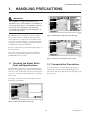


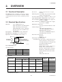
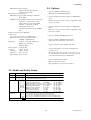
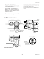
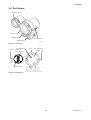
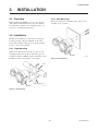
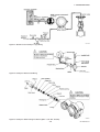
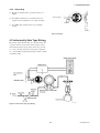

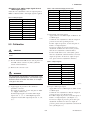
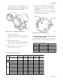
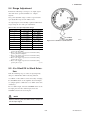
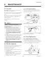

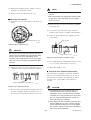

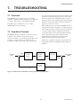

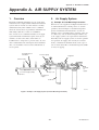
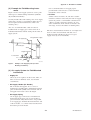
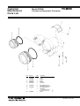
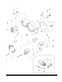
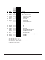


![User`s Manual PK200 電空変換器 [スタイル:S2]](http://vs1.manualzilla.com/store/data/006662005_2-feae5f1db89ea48bcef9ac67fbd68bc0-150x150.png)