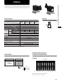
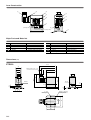
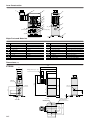
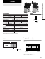
1
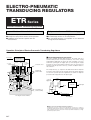
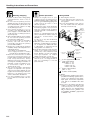
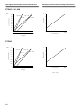
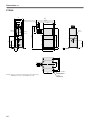
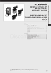
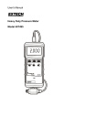
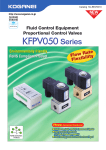
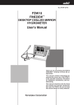
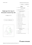
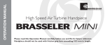
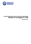
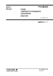
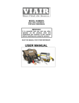
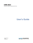
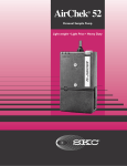
AIR TREATMENT, AUXILIARY, VACUUM,
AND FLUORORESIN PRODUCTS
ELECTRO-PNEUMATIC
TRANSDUCING REGULATORS
CONTENTS
ETR Series
Features, Operation Principle
Application Examples
Handling Instructions and Precautions
Input Signal and Secondary Pressure Characteristics
ETR010
ETR200
ETR600
ETR601
Caution
237
238
239
241
242
244
246
248
Before use, be sure to read the “Safety Precautions” on p. 49.
236
ELECTRO-PNEUMATIC TRANSDUCING REGULATORS
ACCESSORIES
GENERAL CATALOG
ELECTRO-PNEUMATIC
TRANSDUCING REGULATORS
ETR Series
Electro-Pneumatic Transducing Regulators
A fusion of air and electronics
●Flexibly control pressure.
●A sequencer (PC) allows remote control operation.
●Feedback control ensures superior flow rate
characteristics.
Body construction uses P.W.M. control poppet
●Simple construction. Not requiring special air quality.
●Non-bleed type means no air leak problems.
●Any mounting direction is acceptable. It can withstand
strong shocks and vibrations.
Operation Principle of Electro-Pneumatic Transducing Regulators
Input signal
w 2-way
exhaust valve
■Increasing output air pressure A
r Controller
e 2-way
air supply
valve
q Pressure sensor
y Diaphragm
t Pilot chamber
PR
When the controller r input signal increases, the 2-way valve e is
activated and pressure on the pilot chamber t rises. Then, forcing
downward the diaphragm y causes the valve assembly u to move
downward, opening the air supply port i, and causing the supply
pressure P to flow in and output air pressure A to rise. Pressure A is
detected using the pressure sensor q, and the feedback returns to
the controller.
The 2-way valves w, e respond to the difference between output air
pressure A and set pressure by an input signal, and switch supply air
on and off to perform pressure adjustment, to obtain an output air
pressure A that is proportional to the input signal.
2-way air
supply valve
P
2-way
exhaust
valve
A
Controller
Input signal
PR
i Air supply port
u Valve assembly
R
R
P
A
Pressure sensor
This diagram shows the ETR200 .
Block diagram
●What is an electro-pneumatic transducing regulator?
A multi-purpose pressure control device that operates in response to voltage or
current input signals from the outside to continuously step and accurately control high
relief regulator’s (pilot type) pilot section in electro-pneumatic transducers, for highprecision air pressure control.
237
The Koganei Electro-Pneumatic Transducing
Regulator is suitable for such applications as:
Level 1
Setting up test benches simply.
Level 2
Multiple stepping of air cylinder thrust.
Level 3
Controlling valves.
Level 4
Controlling various types of flow dispensers.
Level 5
Controlling tension force in winder equipment.
ELECTRO-PNEUMATIC TRANSDUCING REGULATORS
Application Examples of Electro-Pneumatic Transducing Regulators
Level 1
●Automotive brake equipment
●Automotive electrical parts
●Various kinds of valve
operations
●Research test labs
ETR200
Gauge
Control box
Work for
measurement
Level 2
Level 3
●Automotive parts
●Wristwatch cases
●Print circuit board
●Various kinds of cutting
●Bakeries and snack food processing plants
●Pharmaceutical plants
DYNA cylinder
ETR010
ETR200
Solenoid valve
350-4E2
Control valve
Scale meter
Sequencer
(analog output)
Control box
Level 4
Level 5
●Compact disk manufacturing
●Applying solder paste
●Chemical filling machine
●Video tapes and other magnetic tapes
●Coil wires
●Packaging material winding
●Electrical wiring material winding
ETR200
ETR010
Air brake motor
Koganei
suck back
valve
Tank
Air cylinder
Control box
Index table
Control box
ETR200
Remark: For other examples and technical information materials regarding the applications listed above, consult us.
238
Handling Instructions and Precautions
1. Install in locations where wiring, piping,
and maintenance work is easy to
perform.
2. Do not leave the primary pressure
applied when the electrical power has
been switched OFF. (At this time, the
secondary pressure could rise as high
as the primary pressure.)
3. A bootstrap operation (of 1 to 2
seconds) occurs immediately after the
power supply is switched ON, which
could cause the secondary pressure to
drop temporarily.
4. After switching ON the power supply,
do not leave the primary pressure
lower than the setting value.
5. Do not mount a valve on the ETR’s
primary side that will result in
repeatedly switching the primary
pressure ON and OFF.
6. Electric noise could result in operations
instability. Always take adequate noisereducing measures.
※ For wiring, use shielded wires.
※ Use surge protection for nearby
solenoid valves and inductive loads.
7. Mount in locations that are as distant
from motors and powered lines as
possible. When mounting near inductive
loads and powered lines, always
implement load surge suppression, and
use magnetic shielding for insulation. In
particular, consult us if planning to use
in environments subject to much
external electric noise.
8. The electro-pneumatic transducing
regulator is adjusted to the specifications before being shipped out from
Koganei. Avoid removing or disassembling any of its parts because such
action could result in breakdowns.
9. For other handling issues, see the
User’s Manual included with the
product.
239
General precautions
1. Always thoroughly blow off (use
compressed air) the piping before
plumbing. Entering chips, sealing tape,
rust, etc., generated during piping work
could result in air leaks or other
defective operation.
2. As the interior of the electro-pneumatic
transducing regulator uses precision
parts, the compressed air should be
cleaned air devoid of solid substances,
moisture, etc.
2. Intrusion of contaminated air into the
device could have an adverse effect on
operations characteristics and
durability.
For the use of any other media than
air, consult us.
3. While the system can be used without
lubrication, if lubricating the actuators,
etc. is required, use Turbine Oil Class
1 (ISO VG32) or equivalent. Avoid
using spindle oil or machine oil.
4. The product cannot be used when the
media or the ambient atmosphere
contains any of the substances listed
below. Organic solvents, phosphate
ester type hydraulic oil, sulphur
dioxide, chlorine gas, or acids, etc.
5. If using in locations subject to dripping
water or oil, etc., or to large amounts of
dust, use something to cover and
protect the unit.
Wiring method
1. Removing the connector
(1) Loosen and remove the connector setscrew, and lift off the connector from
the regulator.
(2) Loosen the tightening screw, remove
the seal washer and seal, and push
the body out from the cap.
Tightening
screw
Gasket
Seal washer
Body
Seal
Cap
Setscrew
3:Monitor output
terminal
2:Input signal
terminal
3
Mounting and piping
2
1
1:Power supply
terminal
1:Common terminal
1......Power supply+DC24V terminal
2......Input signal terminal
Blank: DC 1∼5〔V〕
-1: DC 0∼5〔V〕
-2: DC 0∼10〔V〕
-4: DC 4∼20〔mA〕
3......Monitor output terminal
(DC1∼5〔V〕)
.....Common terminal (GND)
2. Wiring
(1) To avoid erratic operation in the electropneumatic transducing regulator due to
electric noise, divide the power supply,
input signal, and monitor output lines
each, and use a shielded 2-wire cable
for each.
(2) The electro-pneumatic transducing
regulator consumes a maximum of 5W
of electrical power. For the power
supply, therefore, use shielded wiring
with a conductor area of 0.4mm2∼0.5
mm2 [0.0006∼0.0008in.2] (equivalent
to AWG24∼22).
ELECTRO-PNEUMATIC TRANSDUCING REGULATORS
Recommendation
Peripheral pneumatic devices are
available for use with the ETR series. See
the following list for reference.
ETR010
TS6-01
Fitting
A, P port
TS8-01
TL6-01
TL8-01
Muffler
R port
KM-1
KM-11
U6-B (0)
Tube
U8-B (0)
Filter
F150-01
ETR200
TS8-02
Fitting
A, P port
TS10-02
TL8-02
TL10-02
PR port
Muffler
R port
150-30A
KM-2
KM-23
U8-B (0)
Tube
U10-B (0)
Filter
F600-02
ETR600
TS10-04
Fitting
A, P port
TS12-04
TL10-04
TL12-04
PR port
Muffler
R port
150-30A
KM-4
KM-41
U10-B (0)
Tube
U12-B (0)
Filter
F600-04
ETR601
TS10-04
Fitting
A, P port
TS12-04
TL10-04
TL12-04
PR port
Muffler
Tube
Filter
R port
150-30A
KM-4
KM-41
U10-B (0)
U12-B (0)
F600-04
240
Input Signal and Secondary Pressure Characteristics
Secondary Pressure and Output Voltage Characteristics
ETR010, 200, 600
1
MPa
V
5
0.9
DC1∼5V
0.7
DC4∼20mA
0.6
0.5
0.4
4
Output voltage
Secondary pressure
DC0∼10V
DC0∼5V
0.8
3
2
0.3
0.2
1
0.1
0
1
0
2
2
4
3
6
4
8
5
10
6
12
7
14
8
16
9
18
10V
0
20mA
0.1 0.2 0.3 0.4 0.5 0.6 0.7 0.8 0.9
1
Secondary pressure
MPa
Input signal
ETR601
MPa
V
0.2
5
0.18
DC0∼5V
DC0∼10V
4
0.14
DC4∼20mA
DC1∼5V
0.12
0.1
0.08
Output voltage
Secondary pressure
0.16
3
2
0.06
0.04
1
0.02
0
0
1
2
3
4
5
6
7
8
9
10V
2
4
6
8
10
12
14
16
18
20mA
0
0.02 0.04 0.06 0.08 0.1 0.12 0.14 0.16 0.18 0.2
Secondary pressure
Input signal
1MPa = 145psi.
241
MPa
Specifications
ELECTRO-PNEUMATIC TRANSDUCING REGULATORS
ETR010
Symbol
Basic model
Item
ETR010
ETR010-1
Media
ETR010-2
ETR010-4
Air
Port size
Rc
1/8
R
P
Pressure setting range
MPa [psi.]
0.005∼0.7 [0.7∼102]
Primary pressure range
MPa [psi.]
Set pressure or more, and 0.9 [131] or less
Proof pressure
MPa [psi.]
Voltage
control
method
Current
control
method
Input
signal
Voltage
DC[V]
Input impedance
Current
1.32 [191]
1∼5
0∼5
0∼10
20
20
42
DC [mA]
──
Ω
──
Input impedance
DC [V]
Output voltage
Output
signal
kΩ
Load impedance
──
──
4∼20
250
1∼5
kΩ
5 or more
DC [V]
Power supply
A
24 (7W)±10%
Linearity ※
±1.0% F.S.
Hysteresis ※
±0.5% F.S.
s
Step response Note
Operating temperature range
(atmosphere and media)
1 or less
5∼50 [41∼122]
°C [ °F]
m/s2 [ft./sec.2]
Vibration resistance
98 [322] or less
Wiring
DIN connector (as standard)
Mass
0.44 [0.97]
kg [lb.]
※ Values are calculated assuming a pressure full span (F.S.) of 0.7MPa [102psi.].
Note: Secondary pressure values assume at no load conditions.
Flow Rate Characteristics
and Relief Characteristics
Order Codes
Basic model
Input signal
ETR010
1
2
4
-
ETR010
Secondary pressure
MPa
0.7
0.6
0.5
0.4
Mounting base is standard equipment.
0.3
●Blank
1
2
4
DC1∼5(V)
DC0∼5(V)
DC0∼10(V)
DC4∼20(mA)
0.2
0.1
20
R/min(ANR)
15
10
5
0
5
Relief flow rate(A→R)
10
15
20
R/min(ANR)
Flow rate(P→A)
Remark: Primary pressure is 0.7MPa [102psi].
1MPa = 145psi. 1R/min = 0.0353ft.3/min.
242
Inner Construction
r
q
w
y
u
u
i
i
e
P
(Primary side)
t
A
(Secondary side)
A
o
Major Parts and Materials
No.
Parts
Materials
No.
Parts
Materials
q
DIN connector
Plastic
t
Pressure sensor
Plastic (diffusion-type semiconductor)
w
Cover
Plastic
y
Circuit board assembly
Glass epoxy
e
Body
Aluminum alloy (anodized)
u
Coil assembly
──
r
Gasket
Synthetic rubber (chloroprene)
i
Plunger
Magnetic stainless
o
Mounting base
Mild steel (zinc plated)
Dimensions (mm)
ETR010
113.3
102
42
Wiring port boreφ6∼φ10
30
67
22.5
65
71.5
A
10.5
R・P
A
P
16
32
55
243
78
4-M4×0.7, Depth 6
Mounting thread
2-φ6.5
Mounting hole
64
11
2
9
R
R c1 /8
10.5
2-Rc1/8
(89.8)
53
27.5
Specifications
ELECTRO-PNEUMATIC TRANSDUCING REGULATORS
ETR200
Symbol
Basic model
Item
ETR200
ETR200-1
Media
ETR200-2
ETR200-4
Air
Port size
Rc
MPa [psi.]
Pressure setting range
MPa [psi.]
MPa [psi.]
Primary pressure range
Proof pressure
Voltage
control
method
Current
control
method
Input
signal
Output
signal
DC[V]
Voltage
Input impedance
kΩ
DC [mA]
Current
Input impedance
1/4
0.01∼0.7 [1.5∼131]
1∼5
0∼5
0∼10
20
20
42
──
──
──
Ω
A
P
1.32 [191]
4∼20
──
250
Output voltage
DC [V]
1∼5
Load impedance
kΩ
DC [V]
24 (7W)±10%
Power supply
R
Set pressure +0.1 [15] or more, and 0.9 [131] or less
5 or more
Linearity ※
±1.0% F.S.
Hysteresis ※
±0.5% F.S.
s
Step response Note
Operating temperature range
(atmosphere and media)
2 or less
5∼50 [41∼122]
°C [ °F]
m/s2 [ft./sec.2]
Vibration resistance
98 [322] or less
Wiring
DIN connector (as standard)
Mass
kg [lb.]
0.74 [1.63]
※ Values are calculated assuming a pressure full span (F.S.) of 0.7MPa [102psi.].
Note: Secondary pressure values assume at no load conditions.
Flow Rate Characteristics
and Relief Characteristics
Order Codes
Basic model
ETR200
Input signal
Secondary pressure
MPa
ETR200
-
1
2
4
0.7
0.6
0.5
0.4
Mounting base is standard equipment.
●Blank
1
2
4
0.3
DC1∼5(V)
DC0∼5(V)
DC0∼10(V)
DC4∼20(mA)
0.2
0.1
500
R/min(ANR)
0
500
Relief flow rate(A→R)
1000
1500
2000
R/min(ANR)
Flow rate(P→A)
Remark: Primary pressure is 0.83MPa [120psi.].
1MPa = 145psi. 1R/min = 0.0353ft.3/min.
244
Inner Construction
!2
q
u
!4
!6
!5
!8
w
e
o
r
t
i
!3
!1
Ay
P
A
(Secondary side)
(Primary side)
R
!0
!7
Major Parts and Materials
No.
Parts
q
DIN connector
w
e
Materials
No.
Parts
Materials
Plastic
!0
Valve
Diaphragm
Aluminum (NBR baked)
!1
Body
Aluminum alloy (anodized)
Valve pin
Brass
!2
Gasket
Synthetic rubber (chloroprene)
r
Valve seat
Brass
!3
Pressure sensor
Plastic (diffusion-type semiconductor)
t
Spring
Piano wire
!4
Circuit board assembly
Glass epoxy
y
Exhaust cover
Aluminum alloy (anodized)
!5
Coil assembly
──
Brass (NBR baked)
u
Cover
Plastic
!6
Plunger
Magnetic stainless
i
Balancer
Brass
!7
Mounting base
Mild steel (zinc plated)
o
Adapter
Aluminum alloy (anodized)
!8
Check valve
Synthetic rubber (NBR)
Dimensions (mm)
113.3
ETR200
42
102
30
Wiring port boreφ6∼φ10
67
22.5
27.5
53
65
P
P
R
R
R c1 /4
A
A
245
55
78
64
4-M4×0.7, Depth 6
Mounting thread
2-φ6.5
Mounting hole
32
12
2
9
3 4. 5
20
14.5
60
119.5
2-Rc1/4
PR
(137.8)
M5×0.8
Specifications
ELECTRO-PNEUMATIC TRANSDUCING REGULATORS
ETR600
Symbol
Basic model
Item
ETR600
ETR600-1
Media
ETR600-2
ETR600-4
Air
Port size
Rc
MPa [psi.]
Pressure setting range
MPa [psi.]
MPa [psi.]
Primary pressure range
Proof pressure
Voltage
control
method
Current
control
method
Input
signal
Output
signal
DC [V]
Voltage
Input impedance
Current
kΩ
1/2
0.01∼0.7 [1.5∼102]
P
1.32 [191]
1∼5
20
0∼5
0∼10
20
42
DC [mA]
──
Ω
──
Input impedance
A
──
──
4∼20
250
Output voltage
DC [V]
1∼5
Load impedance
kΩ
DC [V]
24 (7W)±10%
Power supply
R
Set pressure +0.1 [15] or more, and 0.9 [131] or less
5 or more
Linearity ※
±1.0% F.S.
Hysteresis ※
±0.5% F.S.
s
Step response Note
Operating temperature range
(atmosphere and media)
2 or less
5∼50 [41∼122]
°C [ °F]
m/s2 [ft./sec.2]
Vibration resistance
98 [322] or less
Wiring
DIN connector (as standard)
kg [lb.]
Mass
1.2 [2.65]
※ Values are calculated assuming a pressure full span (F.S.) of 0.7MPa [102psi.].
Note: Secondary pressure values assume at no load conditions.
Flow Rate Characteristics
and Relief Characteristics
Order Codes
Basic model
Input signal
ETR600
1
2
4
-
ETR600
Secondary pressure
MPa
0.7
0.6
0.5
Mounting base is standard equipment.
0.4
●Blank
1
2
4
DC1∼5(V)
DC0∼5(V)
DC0∼10(V)
DC4∼20(mA)
0.3
0.2
0.1
2000
1000
0
1000
2000
3000
R/min(ANR)
R/min(ANR)
Relief flow rate(A→R)
Flow rate(P→A)
Remark:Primary pressure is 0.83MPa [120psi.].
1MPa = 145psi. 1R/min = 0.0353ft.3/min.
246
Dimensions (mm)
ETR600
55
120.8
42
109.5
Wiring port boreφ6∼φ10
30
φ22.5
65
7.5
53
27.5
Rc1/2
M5×0.8
P
P
R
R
142.5
PR
A
A
2
9
17
49
32
83
PR
92
(160.7)
2-Rc1/2
65
Remark: The inner construction and major parts and materials of the
ETR600 are the same as the ETR200. See p.245.
247
100
85
80
40
18.5
4-M4×0.7, Depth 6
Mounting thread
4-φ5.5
Mounting hole
Specifications
ELECTRO-PNEUMATIC TRANSDUCING REGULATORS
ETR601
Symbol
Basic model
Item
ETR601
ETR601-1
Media
ETR601-2
ETR601-4
Air
Port size
Rc
MPa [psi.]
Pressure setting range
MPa [psi.]
MPa [psi.]
Primary pressure range
Proof pressure
Voltage
control
method
Current
control
method
Input
signal
Output
signal
DC [V]
Voltage
Input impedance
Current
kΩ
1/2
0.01∼0.2 [1.5∼29]
0.6 [87]
1∼5
20
P
0∼5
0∼10
20
42
DC [mA]
──
Ω
──
Input impedance
A
──
──
4∼20
250
Output voltage
DC [V]
1∼5
Load impedance
kΩ
DC [V]
24 (7W)±10%
Power supply
R
Set pressure +0.05 [7] or more, and 0.4 [58] or less
5 or more
Linearity ※
±1.0% F.S.
Hysteresis ※
±0.5% F.S.
s
Step response Note
Operating temperature range
(atmosphere and media)
2 or less
5∼50 [41∼122]
°C [ °F]
m/s2 [ft./sec.2]
Vibration resistance
98 [322] or less
Wiring
DIN connector (as standard)
kg [lb.]
Mass
1.2 [2.65]
※ Values are calculated assuming a pressure full span (F.S.)of 0.2MPa [29psi.].
Note: Secondary pressure values assume at no load conditions.
Flow Rate Characteristics
and Relief Characteristics
Order Codes
Basic model
ETR601
Input signal
Secondary pressure
MPa
ETR601
-
1
2
4
0.2
0.15
Mounting base is standard equipment.
●Blank
1
2
4
DC1∼5(V)
DC0∼5(V)
DC0∼10(V)
DC4∼20(mA)
0.1
0.05
800 400
0
400
R/min(ANR)
Relief flow rate(A→R)
800
1200 1600 2000
R/min(ANR)
Flow rate(P→A)
Remark:Primary pressure is 0.25MPa [36psi.].
1MPa = 145psi. 1R/min = 0.0353ft.3/min.
248
Dimensions (mm)
ETR601
55
120.8
42
Wiring port boreφ6∼φ10
30
109.5
φ22.5
65
7.5
53
27.5
Rc1/2
M5×0.8
P
P
R
R
142.5
PR
A
A
2
9
17
49
32
83
PR
92
(160.7)
2-Rc1/2
65
85
100
80
40
18.5
4-M4×0.7, Depth 6
Mounting thread
4-φ5.5
Mounting hole
Remark: The inner construction and major parts and materials of the
ETR601 are the same as the ETR200. See p.245.
調イラストP138 1
249