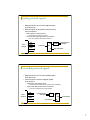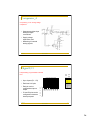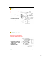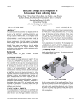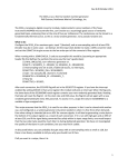
1
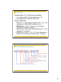
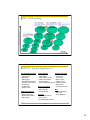
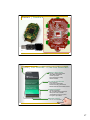
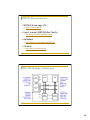
Computational hardware Digital logic (CSE370/351) Programmable logic devices (CSE370/352, CSE467) Gates and flip-flops: glue logic, simple FSMs, registers Two-level PLDs: FSMs, muxes, decoders Field-programmable gate arrays: FSMs, basic data-paths Mapping algorithms to hardware Microprocessors (CSE378/352) General-purpose computer Instructions can implement complex control structures Supports computations/manipulations of data in memory CSE 466 Microcontrollers 1 Microprocessors Arbitrary computations Arbitrary control structures Arbitrary data structures Specify function at high-level and use compilers and debuggers Microprocessors can lower hardware costs If function requires too much logic when implemented with gates/FFs If function does not require higher performance of customized logic CSE 466 Operations are too complex, better broken down as instructions Lots of data manipulation (memory) Ever-increasing performance of processors puts more and more applications in this category Minimize the amount of external logic Microcontrollers 2 1 Microprocessor basics Composed of three parts Data-path: data manipulation and storage Control: determines sequence of actions executed in data-path and interactions to be had with environment Interface: signals seen by the environment of the processor Instruction execution engine: fetch/execute cycle Flow of control determined by modifications to program counter Instruction classes: CSE 466 Data: move, arithmetic and logical operations Control: branch, loop, subroutine call Interface: load, store from external memory Microcontrollers 3 Microprocessor basics (cont’d) Can implement arbitrary state machine with auxiliary data-path CSE 466 Control instructions implement state diagram Registers and ALUs act as data storage and manipulation Interaction with the environment through memory interface How are individual signal wires sensed and controlled? Microcontrollers 4 2 Microprocessor organization Controller Data-path Inputs: from ALU (conditions), instruction read from memory Outputs: select inputs for registers, ALU operations, read/write to memory Register file to hold data Arithmetic logic unit to manipulate data Program counter (to implement relative jumps and increments) Interface Data to/from memory (address and data registers in data path) Read/write signals to memory (from control) control source bus register destination bus source bus CSE 466 file Microcontrollers arithmetic m m logic a d unit r r 5 General-purpose processor Programmed by user New applications are developed routinely General-purpose Must handle a wide ranging variety of applications Interacts with environment through memory CSE 466 All devices communicate through memory data DMA operations between disk and I/O devices Dual-ported memory (e.g., display screen) Generally, oblivious to passage of time Microcontrollers 6 3 Embedded processor Typically programmed once by manufacturer of system Executes a single program (or a limited suite) with few parameters Task-specific Many systems allow firmware updates Can be optimized for a specific application Interacts with environment in many ways Direct sensing and control of signal wires Communication protocols to environment and other devices Real-time interactions and constraints Power-saving modes of operation to conserve battery power CSE 466 Microcontrollers 7 Why embedded processors? High overhead in building a general-purpose system Storing/loading programs Operating system manages running of programs and access to data Shared system resources (e.g., system bus, large memory) Many parts Optimization opportunities As much hardware as necessary for application As much software as necessary for application Can integrate processor, memory, and I/O devices on to a single chip CSE 466 Communication through shared memory/bus Each I/O device often requires its own separate hardware unit Cheaper, portable, lower-power systems Doesn’t require a complete OS, get a lot done with a smaller processor Microcontrollers 8 4 Typical general-purpose architecture CPU Memory Display (with dual-port video RAM) system bus I/O (serial line, keyboard, mouse) Disk Network Interface Sound Interface all the parts around the processor are usually required standard interfaces CSE 466 9 Microcontrollers Typical task-specific architecture medium-speed interactions General Purpose I/O Special I/O Device Driver Microcontroller (CPU+mem+…) ROM RAM Timers Custom Logic high-speed interactions any of the parts around the microcontroller are optional standard interface CSE 466 A/D-D/A Conversion low-speed interactions Microcontrollers 10 5 How does this change things? Sense and control of environment Measurement of time Many applications require precise spacing of events in time Reaction times to external stimuli may be constrained Communication CSE 466 Processor must be able to “read” and “write” individual wires Controls I/O interfaces directly Protocols must be implemented by processor Integrate I/O device or emulate in software Capability of using external device when necessary Microcontrollers 11 Interactions with the environment Basic processor only has address and data busses to memory Inputs are read from memory Outputs are written to memory Thus, for a processor to sense/control signal wires in the environment they must be made to appear as memory bits CSE 466 How do we make wires look like memory? Microcontrollers 12 6 Sensing external signals Map external wire to a bit in the address space of the processor External register or latch buffers values coming from environment Map register into address space Output enable (OE) to get value on to data bus Decoder selects register for reading Lets many registers use the same data bus RD WR WAIT Microprocessor OE to data bus from address bus read signal OUT ADDR IN DATA CSE 466 decoder from environment 13 Microcontrollers Controlling external signals Map external wire to a bit in the address space of the processor Connect output of memory-mapped register to environment Map register into address space Input enable (EN) to take value from data bus Microprocessor Decoder selects register for writing (holds value indefinitely) Lets many registers use the same data bus RD WR WAIT from address bus write signal decoder OUT ADDR DATA CSE 466 EN from data bus Microcontrollers to environment IN 14 7 Time and instruction execution Keep track of detailed timing of each instruction's execution Loops to implement delays Highly dependent on code Hard to use compilers Not enough control over code generation Interactions with caches/instruction-buffers Keep track of time in counters Keeps processor busy counting and not doing other useful things Timer CSE 466 Take differences between measurements at different points in code Keeps running even if processor is idle to save power An independent “co-processor” to main processor Microcontrollers 15 Time measurement via parallel timers Separate and parallel counting unit(s) Co-processor to microprocessor Does not require microprocessor intervention May be a simple counter or a more featured real-time clock Alarms can be set to generate interrupts More interesting timer units CSE 466 Self reloading timers for regular interrupts Pre-scaling for measuring larger times Started by external events Microcontrollers 16 8 Input/output events Input capture Record time when input event occured Can be used in later handling of event Output compare Set output event to happen at a point in the future Reactive outputs Processor can go on to do other things in the meantime e.g., set output to happen a pre-defined time after some input CSE 466 Microcontrollers 17 System bus based communication Extend address/data bus outside of chip Use specialized devices to implement communication protocol Map devices and their registers to memory locations Read/write data to receive/send buffers in shared memory or device Poll registers for status of communication Wait for interrupt from device on interesting events CSE 466 Send completed Receive occurred Microcontrollers 18 9 Support for communication protocols Built-in device drivers For common communication protocols Serial-line protocols most common as they require fewer pins Serial-line controller Special registers in memory space for interaction May use timer unit(s) to generate timing events e.g., RS232, IrDA, USB, Bluetooth, etc. For spacing of bits on signal wire For sampling rate Increase level of integration No external devices May further eliminate need for shared memory or system bus CSE 466 Microcontrollers 19 Microcontrollers Embedded processor with much more integrated on same chip CSE 466 Processor core + co-processors + memory ROM for program memory, RAM for data memory, special registers to interface to outside world Parallel I/O ports to sense and control wires Timer units to measure time in various ways Communication subsystems to permit direct links to other devices Microcontrollers 20 10 Microcontrollers (cont’d) Other features not usually found in general-purpose CPUs Expanded interrupt handling capabilities More instructions for bit manipulations Multiple interrupts with priority and selective enable/disable Automatic saving of context before handling interrupt Interrupt vectoring to quickly jump to handlers Support operations on bits (signal wires) rather than just words Integrated memory and support functions for cheaper system cost Built-in EEPROM, Flash, and/or RAM DRAM controller to handle refresh Page-mode support for faster block transfers CSE 466 Microcontrollers 21 CSE 466 Microcontrollers 22 11 Block diagram of processor (Harvard) Register transfer view of Harvard architecture Separate busses for instruction memory and data memory load path 16 REG 16 AC 16 store path OP N rd wr data Data Memory (16-bit words) addr 16 Z Control FSM 16 IR PC data Inst Memory (8-bit words) 16 16 OP addr 16 CSE 466 23 Microcontrollers Block diagram of processor (Princeton) Register transfer view of Princeton architecture Single unified bus for instructions, data, and I/O load path 16 REG 16 AC 16 OP N rd wr data Data Memory (16-bit words) addr 8 Z Control FSM store path MAR 16 IR PC 16 16 OP 16 CSE 466 Microcontrollers 24 12 The MSP430: Introduction MSP430: An Introduction The MSP430 family Technology Roadmap Typical Applications The MSP430 Documentation MSP430 Architecture MSP430 Devices MSP430 RISC core CSE 466 Microcontrollers 26 13 The Family Broad family of TI’s 16-bit microcontrollers from 1Kbytes ROM, 128 bytes RAM (approx. $1 ) to 256Kbytes ROM, 16Kbytes RAM ( $10) Many subfamilies MSP430x1xx: Flash/ ROM based MCUs offer 1.8V to 3.6V operation, up to 60kB, 8MIPs with Basic Clock. MSP430F2xx: 16 MHz. integrated on-chip oscillator, internal pullup/pull-down resistors MSP430x4xx: 120kB/ Flash/ ROM 8MIPS with FLL + SVS, integrated LCD controller MSP430x5xx: 25 MIPS, 1.8 to 3.6V, Power Management Module for optimizing power consumption, 2x memory CSE 466 Microcontrollers 27 Part numbering convention CSE 466 Microcontrollers 28 14 MSP 430 Roadmap CSE 466 Microcontrollers 29 MSP430 Typical Applications Handheld Measurement Air Flow measurement Alcohol meter Barometer Data loggers Emission/Gas analyser Humidity measurement Temperature measurement Weight scales Medical Instruments Blood pressure meter Blood sugar meter Breath measurement EKG system CSE 466 Utility Metering Home environment Gas Meter Air conditioning Water Meter Control unit Heat Volume Counter Thermostat Heat Cost Allocation Boiler control Electricity Meter Shutter control Meter reading system (RF) Irrigation system White goods Sports equipment (Washing machine,..) Altimeter Bike computer Misc Diving watches Smart card reader Taxi meter Security Smart Batteries Glass break sensors Door control Smoke/fire/gas detectors Microcontrollers 30 15 An MSP430-Based System Adj. Vol. Regul. LCD RS232 RS232 controller Analog I/O 2-axes joystick Switches LEDs Thermistor µC Keypad CSE 466 31 Microcontrollers Another MSP430-Based System CC430F6137 MCU 3-Axis Accelerometer Pressure & Altitude Sensor <1GHz RF • 433, 868 & 915 MHz Temperature Sensor 2-Wire JTAG Access 96 segment LCD Voltage & Battery Sensor Buzzer CR2032 Battery eZ430 Programmer CSE 466 RF Access Point Microcontrollers Chronos Disassembly Tool 32 16 Chronos | Teardown 10/4/10 CSE 466 33 Microcontrollers CC430 | Low-Power RF + Ultra-Low Power MCU MSP430™ Microcontroller • Industry’s lowest power MCU • 16-bit RISC architecture • 27 MHz processor • High-performance analog • Sensor interface CC1101 RF Transceiver SoC • High sensitivity • Low current consumption • Excellent blocking performance • Flexible data rate & modulation format Intelligent Peripherals • 100 nA comparator • 8ch 12-bit ADC offering 200-ksps • 96 segment LCD controller • 128-bit AES security encryption/ decryption coprocessor 64QFN Pin Package • 9.1 mm x 9.1 mm area 34 17 MSP430 Documentation MSP430 home page (TI) User’s manual (MSP430x2xx Family) http://www.ti.com/litv/pdf/slau144e Datasheet www.ti.com/msp430 http://www.ti.com/lit/gpn/msp430f2013 Chronos: CSE 466 http://www.ti.com/lit/pdf/slau292 Microcontrollers 35 MSP 430 Modular Architecture CSE 466 Microcontrollers 36 18 CPU Introduction RISC architecture with 27 instructions and 7 addressing modes. Orthogonal architecture with every instruction usable with every addressing mode. Full register access including program counter, status registers, and stack pointer. Single-cycle register operations. Large 16-bit register file reduces fetches to memory. 16-bit address bus allows direct access and branching throughout entire memory range. 16-bit data bus allows direct manipulation of word-wide arguments. Constant generator provides six most used immediate values and reduces code size. Direct memory-to-memory transfers without intermediate register holding. Word and byte addressing and instruction formats. CSE 466 Microcontrollers 37 MSP430 16-bit RISC CSE 466 Large 16-bit register file eliminates single accumulator bottleneck High-bandwidth 16-bit data and address bus with no paging RISC architecture with 27 instructions and 7 addressing modes Single-cycle register operations with full-access Direct memory-memory transfer designed for modern programming Compact silicon 30% smaller than an ‘8051 saves power and cost Microcontrollers 38 19 CPU Registers CSE 466 Microcontrollers 39 Registers: PC (R0) Each instruction uses an even number of bytes (2, 4, or 6) PC is word aligned (the LSB is 0) MOV #LABEL,PC ; Branch to address LABEL MOV LABEL,PC ; Branch to address contained in LABEL MOV @R14,PC ; Branch indirect, indirect R14 CSE 466 Microcontrollers 40 20 Registers: SP (R1) Stack pointer for return addresses of subroutines and interrupts SP is word aligned (the LSB is 0) Pre-decrement/post-increment scheme MOV 2(SP),R6 ; Item I2 –> R6 MOV R7,0(SP) ; Overwrite TOS with R7 PUSH #0123h ; Put 0123h onto TOS POP R8 ; R8 = 0123h CSE 466 Microcontrollers 41 Registers: SR (R2) CSE 466 C: SR(0) Z: SR(1) N: SR(2) GIE (Global interrupt enable): SR(3) CPUOff: SR(4) OSCOff: SR(5) SCG1, SCG0: SR(7), SR(6) V: SR(8) Microcontrollers 42 21 Status bits CSE 466 Microcontrollers 43 Constant Generators As – source register addressing mode in the instruction word CPE/EE 421/521 Microcomputers 44 22 CISC / RISC Instruction Set CSE 466 Microcontrollers 45 27 Core RISC Instructions CSE 466 Microcontrollers 46 23 Emulated Instructions CSE 466 Microcontrollers 47 51 Total Instructions CSE 466 Microcontrollers 48 24 Double operand instructions CSE 466 Microcontrollers 49 Single Operand Instruction CSE 466 Microcontrollers 50 25 Jump Instructions CSE 466 Microcontrollers 51 3 Instruction Formats CSE 466 Microcontrollers 52 26 Addressing Modes CSE 466 Microcontrollers 53 Register Addressing Mode CSE 466 Microcontrollers 54 27 Register-Indexed Addressing Mode CSE 466 Microcontrollers 55 Symbolic Addressing Mode CSE 466 Microcontrollers 56 28 Absolute Addressing Mode CSE 466 Microcontrollers 57 Register Indirect Addressing Mode CSE 466 Microcontrollers 58 29 Register Indirect Autoincrement Addressing Mode CSE 466 Microcontrollers 59 Immediate Addressing Mode CSE 466 Microcontrollers 60 30 Code Reduction Effect of Constant Generator CSE 466 Microcontrollers 61 Machine Cycles for Format I Instructions CSE 466 Microcontrollers 62 31 Machine Cycles for Format II/III Instructions CSE 466 Microcontrollers 63 MSP430 Memory Model CSE 466 Microcontrollers 64 32 Memory Organization CSE 466 Microcontrollers 65 MSP 430 Architecture: A Closer Look CSE 466 Microcontrollers 66 33 MSPx430x14x Architecture 64 TQFP (The The Thin Quad Flat Pack package CSE 466 Microcontrollers 67 Microcontrollers 68 Basic Clock System Basic Clock Module provides the clocks for the MSP430 devices CSE 466 34 Watchdog Timer WDT module performs a controlled system restart after a software problem occurs • Can serve as an interval timer (generates interrupts) • WDT Control register is password protected • Note: Powers-up active CSE 466 Microcontrollers 69 Microcontrollers 70 Timer_A Timer_A is a 16-bit timer/counter with three capture/compare registers • Capture external signals • Compare PWM mode • SCCI latch for asynchronous communication CSE 466 35 Comparator_A Comparator_A is an analog voltage comparator • Supports precision slope analog-to-digital conversions • Supply voltage supervision, and • Monitoring of external analog signals. CSE 466 71 Microcontrollers Digital I/O Independently programmable individual I/Os Function Select Register PxSEL yes yes yes no Interrupt Enable Register PxIE yes no Interrupt Flag Register PxIFG yes no Direction Register PxDIR yes yes Output Register PxOUT yes yes yes yes • Each has 8 I/O pins • P1 and P2 pins can be configured to assert an interrupt request CSE 466 Port3 … Port6 Interrupt Edge Select Register PxIES • Up to 6 ports (P1 – P6) • Each pin can be configured as input or output Port1 Port2 Input Register PxIN P1. P2. P3. 7 6 5 4 3 2 1 0 P4. P5. P6. Microcontrollers 72 36 ADC12 High-performance 12-bit analog-todigital converter • More than 200 Ksamples/sec • Programmable sample& hold • 8 external input channels • Internal storage CSE 466 Microcontrollers 73 USART Serial Port The universal synchronous/ asynchronous receive/transmit (USART) peripheral interface supports two serial modes with one hardware module • UART or SPI (Synchronous Peripheral Interface) modes • Double-buffered • Baud-rate generator CSE 466 Microcontrollers 74 37