1
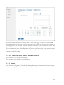
Contents
Chapter 1: Introduction
1.1
1.2
1.3
9
10
Safety Instructions ...................................................................... 10
Included in delivery ..................................................................... 11
Standard practice
........................................................................
Chapter 2: Installation
2.1
2.2
2.3
2.4
2.4.1
2.4.2
2.4.3
2.4.4
2.4.5
2.4.5.1
2.4.5.2
2.4.5.3
2.4.6
2.5
2.5.1
2.5.2
2.5.3
2.5.4
2.5.5
2.6
2.6.1
2.6.2
2.6.3
2.6.4
2.7
2.7.1
2.7.2
2.7.3
2.8
2.8.1
2.8.2
2.9
2.9.1
2.10
13
13
Connection to inverter ................................................................... 14
Terminal block connector ................................................................ 14
SMA .................................................................................... 15
Note - PiggyBack mixed mode ............................................................ 15
Bluetooth Operation ...................................................................... 15
Special RS485 PiggyBack (Manufacturer: Solare Datensysteme Ltd.) .......................... 16
Important Notes for Installation ........................................................... 16
Installation ............................................................................... 17
Connection options
.....................................................................
Wiring scheme .............................................................................17
Control board without PiggyBack ...........................................................18
Control board with PiggyBack ...............................................................18
20
KACO - Powador / PVI-Blue Planet with RS485/EIA485 interface ....................... 20
Powador ................................................................................. 21
PVI-Blue Planet .......................................................................... 21
Wiring ................................................................................... 21
Terminal block - Powador - Models: ........................................................ 21
Terminal block - PVI-Blue Planet - Models: ................................................. 22
SolarMax - Series S, C and E with RS485/EIA485 interface ............................... 23
S and C Series ............................................................................ 23
Cx Series ................................................................................ 24
E Series ................................................................................. 24
Wiring ................................................................................... 24
Fronius - IG 15-60 (HV) and IG 35 + to IG 150+ with ComCard ......................... 25
Installation Fronius ComCard ............................................................. 25
Communication Address .................................................................. 26
Wiring ................................................................................... 26
Danfoss – Inverters ..................................................................... 27
RS485/EIA485 interface .................................................................. 27
Wiring ................................................................................... 28
Mitsubishi with RS485/EIA485 interface ................................................. 29
Wiring ................................................................................... 29
Power-One/Aurora ..................................................................... 29
Original SMA RS485/EIA485 PiggyBack (Manufacturer: SMA)
..............................
2.10.1
2.11
2.11.1
2.11.2
2.12
2.12.1
2.12.2
2.12.3
2.13
2.13.1
2.14
2.14.1
2.15
2.15.1
2.16
2.16.1
2.16.2
2.17
2.17.1
2.18
2.18.1
2.19
2.19.1
2.20
2.20.1
2.21
2.21.1
2.22
2.22.1
2.22.2
2.22.3
2.23
2.24
2.25
2.26
2.26.1
2.26.2
2.26.3
2.27
2.28
2.29
4
30
Sunways – AT/NT ...................................................................... 30
Terminal strip 750V - Models: ............................................................. 31
Terminal strip 850V - Models: ............................................................. 31
Vaillant - auroPOWER VPI/1 and VPI (RS485/EIA485) ................................. 31
Vaillant - auroPOWER VPI/1 ............................................................. 32
Vaillant – auroPOWER VPI ............................................................... 32
Wiring ................................................................................... 32
Solutronic (RS485/EIA485) ............................................................. 34
Wiring ................................................................................... 34
Schüco SGI Series (RS485/EIA485) ..................................................... 34
Wiring ................................................................................... 35
REFUSOL .............................................................................. 35
Wiring ................................................................................... 36
Kostal Pico / Solar-Fabrik Convert T (RS485/EIA485) ................................... 37
Wiring ................................................................................... 37
Multi-String technology ................................................................... 38
Mastervolt with (RS485/EIA485) ........................................................ 38
Wiring ................................................................................... 38
Suntension (Sunville) / Phoenixtec (RS485/EIA485) ..................................... 39
Wiring ................................................................................... 39
Diehl AKO with RS485/EIA485 interface ............................................... 40
Wiring ................................................................................... 40
Connecting SolarLog1000 Analogue Modem Package ..................................... 41
Included in delivery: SolarLog1000 Modem Package ......................................... 42
Connecting the SolarLog1000 Mobile Package ............................................ 42
Included in delivery: SolarLog1000 Mobile Package .......................................... 42
Connecting the MT Sensor Box .......................................................... 42
Assembly ................................................................................ 43
Wiring ................................................................................... 43
Initial startup ............................................................................. 44
Connecting external electricity meters .................................................... 44
Attaching large displays .................................................................. 45
RS485/EIA485 wiring ................................................................... 45
S0 output wiring ......................................................................... 46
Current controlled S0 output .............................................................. 46
Contact controlled S0 output .............................................................. 46
Pulse factor .............................................................................. 46
Connecting Relays ....................................................................... 47
Connecting Alarm contacts .............................................................. 47
Connection to a PC / Network .......................................................... 48
Terminal block - Outdoor - Models:
........................................................
Chapter 3: Manual
3.1
3.1.1
3.2
3.2.1
3.3
3.3.1
3.3.2
3.3.3
3.4
3.4.1
3.4.1.1
3.4.1.2
3.4.1.3
3.4.1.4
3.4.1.5
49
49
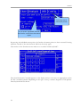
Menu Structure Touchscreen Display ....................................................... 53
PC display .............................................................................. 54
Menu structure PC display ................................................................ 54
Initial startup ............................................................................ 54
Start configuration ........................................................................ 55
Inverter detection ........................................................................ 56
Inverter Configuration .................................................................... 57
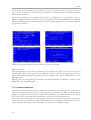
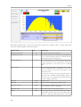
Display menu navigation ................................................................. 58
Graphic ................................................................................. 58
Touchscreen Display
....................................................................
Overview .................................................................................58
Day graphic ...............................................................................59
Month graphic .............................................................................62
Year graphic ...............................................................................63
Total graphic ..............................................................................64
3.4.2
3.4.2.1
3.4.2.2
3.4.2.3
Diagnosis ................................................................................ 64
Messages ..................................................................................64
Inverters event log .........................................................................65
Alarm contact (anti-theft) ...................................................................66
3.4.3
3.4.3.1
3.4.3.2
3.4.3.3
USB ..................................................................................... 66
Copy data .................................................................................66
Data backup ...............................................................................67
Firmware Update ..........................................................................68
3.4.4
3.4.4.1
3.4.4.2
3.4.4.3
3.4.4.4
3.4.4.4.1
3.4.4.4.2
3.4.4.4.3
3.4.4.4.4
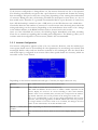
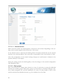
Configuration ............................................................................ 68
Initial configuration ........................................................................68
Inverter detection ..........................................................................70
Inverter Configuration ......................................................................71
Network Settings ...........................................................................73
Dialogue 1 – Basic settings ................................................................73
Dialogue 2 – Network Router ..............................................................74
Dialogue 3 – Analogue Modem ............................................................74
Dialogue 4 – GPRS Modem ...............................................................75
3.4.5
3.4.5.1
3.4.5.2
3.4.5.3
Internet ................................................................................. 76
Basic settings ..............................................................................76
email/SMS ................................................................................76
Homepage ................................................................................76
3.4.6
3.4.6.1
3.4.6.2
3.4.6.3
Advanced ................................................................................ 77
Plant monitoring ...........................................................................77
Large display ..............................................................................77
RS485/EIA485 wireless package ............................................................78
3.4.7
3.4.7.1
Internal .................................................................................. 78
System ....................................................................................78
3.5
Configuration via PC
3.5.1
78
Basic Configuration ....................................................................... 79
....................................................................
5
3.5.1.1
3.5.1.1.1
3.5.1.2
3.5.1.3
3.5.1.4
3.5.1.4.1
3.5.1.4.2
3.5.1.4.3
3.5.1.4.4
3.5.1.4.5
3.5.1.5
3.5.1.5.1
3.5.1.5.2
3.5.1.5.3
3.5.1.5.4
3.5.1.6
LAN - Network Settings ....................................................................79
Internet access ...........................................................................80
Plant groups ...............................................................................80
Inverters order .............................................................................81
Inverter ...................................................................................83
Connected generator power ................................................................83
Pac correction factor ......................................................................83
Product label .............................................................................84
Monitoring ...............................................................................84
Graphic Scaling ...........................................................................86
Forecast ...................................................................................86
Plant size ................................................................................87
Feed-in tariff .............................................................................87
Annual target .............................................................................87
Monthly share ............................................................................87
Graphic ...................................................................................87
3.5.2
3.5.2.1
3.5.2.2
3.5.2.3
3.5.2.4
3.5.2.5
3.5.2.6
Advanced ................................................................................ 88
Internet ...................................................................................88
email ......................................................................................89
SMS ......................................................................................91
Export ....................................................................................93
Fault ......................................................................................94
Status and error codes of SolarMax inverters .................................................95
3.5.3
3.5.3.1
3.5.3.1.1
3.5.3.1.2
3.5.3.1.3
3.5.3.1.4
3.5.3.2
3.5.3.2.1
3.5.3.2.2
3.5.3.3
Internal .................................................................................. 95
Backup ....................................................................................96
Backup - automatically ....................................................................96
Backup - manually ........................................................................96
Data correction ...........................................................................97
Data import of existing day's data ..........................................................97
System ....................................................................................98
Date/Time ...............................................................................99
Additional Password Question .............................................................99
Update ...................................................................................100
3.6
Homepage
3.6.1
3.7
3.7.1
3.7.2
3.7.3
3.7.4
3.7.5
3.7.6
3.7.7
3.7.8
3.7.9
3.7.10
6
101
Free Homepage ......................................................................... 102
Automatic alerts ....................................................................... 102
Inverter failure message - email ........................................................... 102
Inverter failure message - SMS ........................................................... 102
Fault alert from performance monitoring - email ........................................... 102
Fault alert from performance monitoring - SMS ........................................... 103
Fault alert from status/error code monitoring - email ....................................... 103
Fault alert from status/error code monitoring - SMS ....................................... 103
Alarm notification via alarm contact - email ............................................... 103
Alarm notification via alarm contact – SMS ................................................ 103
Yield overview – email .................................................................. 104
Yield overview – SMS ................................................................... 104
.............................................................................
104
PC Visualization ........................................................................ 105
3.8
Yield data
3.8.1
3.8.1.1
3.8.1.2
3.8.1.3
3.8.1.4
Daily overview ............................................................................105
Monthly overview .........................................................................107
Yearly overview ...........................................................................108
Total overview ............................................................................109
3.9
3.9.1
3.10
3.11
3.11.1
3.12
3.13
..............................................................................
111
Event log ............................................................................... 111
Dial-in using an Analogue Modem ...................................................... 113
Useful software ........................................................................ 116
Printing ................................................................................ 117
LED status display ..................................................................... 117
Reset button ........................................................................... 118
Diagnosis
..............................................................................
Chapter 4: Technical Data
4.1
4.2
4.3
4.4
119
119
Timer ................................................................................. 120
Activity log ............................................................................ 120
CE Declaration of Conformity ......................................................... 121
Internet ports
..........................................................................
7
1
Introduction
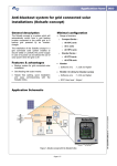
The SolarLog1000 represents the latest generation of the SolarLog series. Building on the web
technology of previous devices, there have been many wishes and suggestions consistently implemented into this device.
The modern display with touchscreen and extensive connectivity options open up unprecedented
possibilities. The new case design is not only aesthetically pleasing but also very practical. This
allows all the cables to be kept hidden and at best completely invisible to the rear.
The SolarLog1000 is a device that can support a variety of inverters supported by its two data
interfaces. Environmental data such as sunlight radiation and temperatures, even wind measurements can be recorded. The data can be loaded onto a USB stick and graphically analysed later
on a PC.
The integrated S0 pulse counter connection can connect digital electricity meters and hence measure electricity consumption. The SolarLog then automatically calculates an energy balance, offsetting its own electricity consumption.
Last but not least, the SolarLog1000 can attach large displays, through the S0 pulse output, or parallel to the inverter via the RS485/EIA485 interface.
The Bluetooth module is optionally available with the SolarLog1000 and can connect the latest
generation of SMA inverters wirelessly.
All these capabilities go to help ensure your photovoltaic system achieves the desired yield for a
long time and problems can be quickly identified and resolved.
In this sense, we wish you every success working with the SolarLog1000 with many profitable
and sunny days.
9
1 Introduction
1.1 Standard practice
The manual consists of 2 parts. First, the installation process is described, i.e. the assembly of the
SolarLogs and the wiring of the inverter to the SolarLog. Then follows the user's manual in
which the configuration and further operation will be described in detail.
Please get to know the device before installing anything. Especially during the initial
installation you should take some time to go through the manual - and not simply just "go
for it".
1.2 Safety Instructions
Read first prior to startup, the following safety instructions.
Our products leave the factory in perfect condition.
In order to maintain this condition, care must be taken in dealing with the equipment (transport,
storage, installation, startup, operation, maintenance, taking out of service). These safety instructions, model plates, labels and safety precautions must be observed, otherwise it can endanger
people's lives and the product itself, and other installations can be damaged.
These safety precautions apply in the Federal Republic of Germany. When used in other countries the relevant national regulations apply.
If the information with these safety precautions should not be sufficient, you can contact the
manufacturer at the given address at any time.
Please check the packaging and claim any damages immediately with the delivery company.
Make sure before turning on, that the power adapter has no damages. If in doubt, consult an
electrician or get in touch with the address at the end of this manual.
Before turning on, please make sure the voltage of the device is identical with the mains supply
in your country.
The device may only be operated with the included power adapter.
If the power adapter comes directly out of a cold environment to a warm environment, condensation may occur. Wait until the temperature compensation has taken place. To start the
device without the temperature compensation is life-threatening!
Repairs should only be performed by authorized personnel. Please contact the mentioned
address at end of the manual.
The power adapter should be checked regularly for damage. In the case of damage to the power
adapter, it needs to be immediately taken out of service and replaced.
10
The device is not suitable for outdoor use
Before cleaning: unplug the device! For cleaning use a gentle detergent with a damp cloth. Never
clean when dripping wet!
Other notes:
The SolarLog1000 operates on 12Volt DC (12VDC, max. 24VDC). Running the unit on a different voltage will invalidate the warranty. Please use only the enclosed power adapter.
The SolarLog1000 has IP20 standard protection and is designed exclusively for installation in dry,
dust-free interiors.
The relay can be used with maximum 24VoltDC and loaded to 5A.
Before any cable connection between the SolarLog1000 and inverter is made, the inverters must
be without any power. That means the AC side must first be separated, then the DC-side. Then
wait at least 5 minutes until the capacitors in the inverters have discharged.
1.3 Included in delivery
The SolarLog1000 is delivered with the following components:
1.SolarLog1000 – Basic Unit
2.12Volt Power adapter
3.Manual
4.Terminal block connectors for all connections: (except CAN): 2x 3-pin, 1x 4-pin, 2x 6-pin
5.4x wall plugs (dowels) and screws for wall mounting
For connection to a PC or network you need a network cable (RJ45 CAT5 or CAT6) in the corresponding length.
Furthermore, you will need suitable cable material for the wiring of the inverters to each other.
Optionally available are suitable, prefabricated cable-sets for the respective inverter manufacturers. The cables have a length of 3m.
11
2
Installation
T
he installation of the SolarLog1000 must take place indoors and protected from dust. For
outdoor and dusty environments, the SolarLog needs to have appropriate protective housing.
The assembly is via 4 mounting points on the rear of the housing. This requires the removal
of the two housing shells top and bottom.
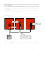
2.1 Connection options
The SolarLog1000 has extensive connections at the housing bottom and top.
Bottom:
Relay
Relay, for switching external signals. For example rotating flashing beacon/light, etc.
RS485-A
First RS485/EIA485 interface. Connection to inverter, Sensor Box or large display
(inactive, when the optional Bluetooth interface is in use)
RS485/RS422B
Second RS485 interface (RS422 for Fronius/Phoenixtec). Connection to inverter,
Sensor Box or large display
Power 12V
12 Volt DC voltage input (max. 24VDC)
Network
Ethernet network interface, 10/100 MBit
RS232/EIA232 RS232/EIA232 Modem Interface Connecting an analogue or GPRS Modem
Top side:
S0 In/Out
S0 pulse input for connection to external electricity meter. S0 pulse output for connection to external large display
13
2 Installation
Alarm
Contact loop for connection to anti-theft device. With optical cables transfers up to
5km.
CAN
CAN bus, for future extensions. Currently unused. No terminal strip is included for
this socket.
USB
USB host connection. Suitable for USB sticks up to 2GByte capacity (Warning: Not
suitable for connecting to PCs!)
Reset
Reset button. Multi-function: 1. Restart SolarLog, 2. Reset to factory settings
2.2 Connection to inverter
Since the SolarLog1000 communicates directly with each inverter, the appropriate data cable is
required. For the connection of SolarLog1000 to the first inverter there are green terminal block
connectors.
Note: pre-assembled cable sets, suitable for your inverter, are available as accessories.
Since each inverter manufacturer uses different wiring and connections, you must have the relevant data cable connected correctly. The following chapters describe the manufacturer supported
connection configurations.
Note: It is essential that you follow the instructions from the manufacturer for connecting the
data cables. These instructions can be taken from the appropriate manufacturer's documentation.
2.3 Terminal block connector
The SolarLog1000 has 2 RS485/EIA485 interfaces, each marked by "A" and "B". The "B" interface can also be used as a RS422 interface (for Fronius/Phoenixtec inverters).
RS485 A:
4-pin green connector
1
4
RS485/RS422-B:
6-pin green connector
1 4 6
The numbering of the connecting plugs are from left to right, from 1 to 4 and 6.
14
The assignment of the connectors are as follows:
Pin
RS485-A RS485-B RS422 (for Fronius/Phoenixtec)
1
Data+
Data+
T/RX+
2
12V
12V
12V
3
Earth
Earth
Earth
4
DataDataT/RX5
R/TX+
6
R/TXNote: The term "data+" / "data-" is manufacturer specific. Sometimes "A" and "B"
are used/described here, or other combinations. Please adhere exactly to the description in
this manual, otherwise the inverter will not be detected!
2.4 SMA
Please note: For SMA inverters there are
2 different connection options, depending on which RS485-PiggyBack is built
into the inverter.
Careful! - different wiring!
Original SMA RS485 PiggyBack:
3-pin Wiring
Special RS485 PiggyBack:
4-pin Wiring
Both PiggyBacks can be fully integrated and installed into all SMA inverters of type "SunnyBoy"
(exception: SB3000/4000/5000TL-20 Next Generation) or of type "Sunny Mini Central".
Important note: Never open the casing of the inverter if it is live. Observe strictly the instructions in the SMA manual.
2.4.1 Note - PiggyBack mixed mode
The special RS485 PiggyBack can also be used in mixed mode with the original SMA PiggyBack
modules. They must also have a 4-wire cabling in place. However, never connect clamp 2 (yellow
SolarLog) with clamp 3 (inverter with Original-PiggyBack/Data Module)
2.4.2 Bluetooth Operation
Note:
1.The Bluetooth operation is only possible when the optional Bluetooth module is installed on
SolarLog1000.
15
2 Installation
2.Currently only inverters SMA-SB3000/4000/5000-20 support wireless Bluetooth operation
(May 2009)
For the Bluetooth operation, there's no preparation necessary on the inverter. The SolarLog1000
currently can read a maximum of 7 Bluetooth SMA inverters
The detection should take place in the same room as where the inverter is. This will stop detection failures due to lack of range. Afterwards, you can then test the SolarLog even further away
from the inverter. Signal strength display is unfortunately not possible.
2.4.3 Special RS485 PiggyBack (Manufacturer: Solare Datensysteme Ltd.)
Note: Here a 4-pin wiring is needed!
The special PiggyBack is a simple RS485 interface converter without controller or without its
own "intelligence". Through the simple and robust design, disturbance behaviour on the inverter
is eliminated. When correctly installed and in compliance with the installation requirements, the
technical data and properties of the inverter remain unchanged. The PiggyBack is galvanically
isolated and has a 6.5 kV isolation protection. Each PiggyBack runs individually a complete functional test on the SMA Inverter.
Note: The Special PiggyBack may only be combined and operated with the SolarLog1000.
The Special RS485 Piggy-backs are compatible with inverters of type
−SB-SunnyBoy (but not to the SB-3000/4000/5000TL-20 NextGeneration, here the original
SMA RS485 Data module must be used)
−SMC SunnyMiniCentral
−SWR inverter (built from 2001 onwards). Possibly the display needs to be dismantled to add-on
the PiggyBacks. This "space problem" exists also on the original SMA PiggyBack.
Please check the completeness of the supplied accessories:
1x isolation tube for data cable
1x Jumper
1x screw connection/feed through Inverter-PG 16 (M22)
1x flat power distributor for connection to housing/earth
2.4.4 Important Notes for Installation
For the fitting of PiggyBack interface cards, the inverter must be opened. This may only be carried out by trained professionals. You should also read all the instructions of the available
inverter manual.
16
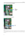
2.4.5 Installation
Work on the inverter must carried out exclusively with a separate power supply. First disconnect
the inverter on the AC side, then from the DC side. Then wait 30 minutes until all the live parts
are discharged.
Also, please note that in the inverter and on the interface card are sensitive electronic components which can be destroyed by static discharge.
2.4.5.1 Wiring scheme
SMA Inverter 1
SMA Inverter 2
SMA-Inverter x
Special
PiggyBack
Jumper
set
Insulating
tube
SolarLog
4-wire, shielded
Cable
Step 1
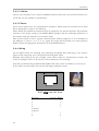
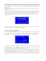
Insert first the PiggyBack on the control board in the inverter. Make sure the word "below" is
visible on the bottom left side of the control board (see Figure 2 below). Note: The lower pin
row must be aligned left.
17
2 Installation
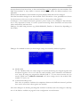
2.4.5.2 Control board without PiggyBack
This is
where the
PiggyBack is
attached
2.4.5.3 Control board with PiggyBack
Label:
Below
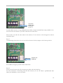
Step 2
Now the individual inverters must be wired to one another. You need a 4-pin, shielded data cable
(e.g. 25m ring, Solare Datensysteme order no. 220014). Connect each of the 4 contacts (2,3,5,7)
on the terminal block of inverter 1 to inverter 2 and inverter to 3, etc. until you have connected
all inverters.
18
Terminal
block strip
Contacts
2,3,5,7
In older SMA inverters of type SWR there's possibly a 10-pin terminal block strip available. Connect here also the contacts 2,3,5 and 7 and leave the others free.
Please make sure that the data cable in the interior of the inverter is fed through the silicone
insulation strips.
Step 3
A terminating resistor has to be set on the last inverter. Set the jumper to the lowest position:
Jumper set
(bottom)
The middle and upper position must remain free!
Step 4
Now you need connect the first inverters per cable with the SolarLog.
For the connection of SolarLog with the first inverter you can use either a prefabricated data
cable (not included) or your own cable.
19
2 Installation
Pull the exposed wires through the cable opening of the inverter and connect them
SolarLog
Terminal strip in the inverter
White
(1)
2
Yellow
(2)
3
Green
(3)
5
Brown
(4)
7
Pull the data cable through the enclosed insulation tube. Connect terminal strip 5 of the inverter
with the accompanying flat pin on the inverter casing.
This completes the hardware installation. You can close the inverter and turn it on.
2.4.6 Original SMA RS485/EIA485 PiggyBack (Manufacturer: SMA)
Note: A 3-pin wiring is required!
The installation is very detailed in the SMA PiggyBack manual, enclosed with the interface board.
The wiring of the inverters with one another is described on page "6 from 8" under "Wiring a
SB/SWR via RS485 to a PC". Connect each individual inverter as in the SMA manual with a
shielded 3-pin data cable.
Then you set jumper A on the PiggyBack of the last inverter as shown on page "5 of 8" and "6
of 8" in the SMA's manual.
For the connection of the SolarLog with the first inverter you can use either a prefabricated data
cable (accessories not included) or your own cable.
Pull the exposed wires through the cable opening of the inverter and connect them
SolarLog
Terminal strip in the inverter
White
(1)
2
Green
(3)
5
Brown
(4)
7
Pull the data cable through the enclosed insulation tube. Connect terminal strip 5 of the inverter
with the accompanying flat pin on the inverter casing.
This completes the hardware installation. You can close the inverter and turn it on.
2.5 KACO - Powador / PVI-Blue Planet with RS485/EIA485 interface
Important note: Never open the casing of the inverter if it is live. Observe strictly the instructions in the KACO manual.
20
2.5.1 Powador
All Powador models have the RS485 interface already integrated from the factory. The interface
must be activated through the operating display. Additionally, each inverter needs a separate communication address assigned to it. It is advisable for the addresses to start at 1, i.e. 1, 2, 3, etc.
Again, this setting will be carried out via the operation display. Follow the instructions in the
KACO manual.
The KACO-Central Inverters are shown as 3 separate inverters in the SolarLog. If for example
two central inverters are available and assigned with address 1 and 2 per RS485 interface, that
would give a total of 6 inverters showing up in the SolarLog.
2.5.2 PVI-Blue Planet
The PVI-BluePlanet models were shipped up to the middle of 2005 and shipped from the factory with an optional RS232 or RS485 fitted. To operate with the SolarLog1000 the RS485 option
is absolutely necessary. The changing of the interface is possible via the Kaco company. Please
ask your installer about this, or KACO directly.
Each inverter needs to have a separate communication address assigned to it. Assignment is
made via a DIP switch inside the inverter. Follow the instructions in the KACO manual. It is
advisable for the addresses to start at 0, i.e. 0, 1, 2, 3, etc.
Note: If the DIP switch is missing on the control board, then it's the RS233 version of the PVIBlue Planet inverter.
2.5.3 Wiring
The wiring of each inverter is carried out by terminal strips that are placed and located inside the
device.
2.5.4 Terminal block - Powador - Models:
Powador built prior to 2006/2007
21
2 Installation
Powador from 2006/2007 onwards (Termination via DIP switches)
Powador 8000xi (6400xi/7200xi):
The 8000xi models are interesting from a cabling side, because here, three 8000xi can be combined together in a group. Similarly, it is also possible to use 1 or 2 devices without grouping
them. The wiring is always completely different. Detailed instructions can also be found in the
Installation manual for KACO inverters.
8000xi as a group:
•Here, one of the three inverters is set per jumper as the "Master" whereas the other two act as a
"slave". Warning! A set jumper ALWAYS means "Slave", pulled jumper ALWAYS "Master" regardless of the labelling on the motherboard. That means, on the master inverter, the jumper
should be pulled, the two slaves must have the jumper set.
•The data cable of the SolarLog will be attached to the terminal strip "LOGGER" of the "Master" inverter
•The 3 inverters are also connected amongst each other via the terminal strip "SYM" .
•All 3 inverters must be equipped with a sequential RS485/EIN485 address which can be configured via the display on the inverter.
•„SYM-Bus" needs to be turned to active on the display of the inverter
8000xi separately:
•Inverter changed to "Slave", i.e. the jumper has to be set.
•The data cable of SolarLog will be attached to the terminal strip "SYM" of the "slave" inverter
•All inverters must be equipped with a sequential RS485/EIN485 address which can be configured via the display on the inverter.
•„SYM-Bus“ needs to be turned to inactive in the configuration on the display of the inverter
2.5.5 Terminal block - PVI-Blue Planet - Models:
Connect each inverter with each other as in the Kaco manual with a shielded 2-pin data cable via
the RS485 terminal strips. There are two RS485 ports, so that the wiring can be passed through.
Connect each terminal A with terminal A of the next inverter and accordingly with the terminals
B.
22
For the connection of the SolarLog with the first inverter, one can use either a prefabricated data
cable (accessories not included) or your own cable.
Pull the exposed wires through the cable opening of the inverter and connect them
SolarLog
Terminal strip in the inverter
White
(1)
B
Brown
(4)
A
BluePlanet / Series 1- Powador:
In addition, a terminating resistor with 330Ohm (enclosed with inverter) needs to be set at the
terminal block on the inverter furthest from the SolarLog. The terminating resistor connects the
free terminal A with terminal B.
Series 2-Powador:
In addition, a terminating resistor on the internal DIP switch (see picture above) to the furthest
inverter from the SolarLog must be set. Please take care to switch DIP switches from the other
inverters to "Off", otherwise it won't be possible to have correct data communication.
Note: If the cable lengths are kept relatively short, the terminating resistor may be omitted in certain circumstances.
2.6 SolarMax - Series S, C and E with RS485/EIA485 interface
Important note: Never open the casing of the inverter if it is live. Observe strictly the instructions of the Sputnik/SolarMax manual.
2.6.1 S and C Series
All the S/C models have the RS485 interface already integrated from the factory. Each inverter
needs to have a separate communication address assigned to it. It is advisable for the addresses to
start at 1, i.e. 1, 2, 3, etc. Again, this setting will be carried out via the operation display. Follow
the appropriate instructions in the SolarMax manual.
S Series: See to it on the inverter's display that only the RS485 interface is enabled (factory
default), and not the built-in Ethernet interface.
Note: The factory default address setting of the inverter is 255, which is not a valid address number. Therefore, even if only 1 inverter is attached to the SolarLog, the address has to be set
manually to "1".
23
2 Installation
2.6.2 Cx Series
The Cx-series models do not contain any RS485 interfaces and need to be retrofitted. Please contact in this case the installer or manufacturer.
2.6.3 E Series
The E-series models have no communication interfaces, which means an interface has be fitted
before being able to attach to the SolarLog.
Please follow the installation instructions that are attached to the relevant interface. Pay particular
attention to the proper setting of the RS485/RS232 Jumpers and the terminating resistance on
the interface card (See manual of the interface card).
Each inverter needs to have a separate communication address assigned to it. It is advisable for
the addresses to start at 1, i.e. 1, 2, 3, etc. Again, this setting will be carried out via the operation
display. Follow the appropriate instructions in the SolarMax manual.
2.6.4 Wiring
Use the RJ45 format for attaching and connecting the RS485 data cable plug to the inverter.
These are the same plugs as in conventional network patch cables.
Warning! The SolarLog also has an RJ45 socket. Please under no circumstances connect this
socket to the RJ45 socket of the inverter. This could destroy the SolarLog!
Note: We recommend the prefabricated SolarMax data cable, which is available as an accessory.
If the cable is custom-made, then use the following termination circuit:
8
1
RJ45-plug from the front
RJ45 Pin
1
2
3
4
5-unused
6-unused
7
8
24
SolarLog RS485
2
2
3
3
1
4
The wiring of each inverter to each other is carried out with conventional network cable, with a
RJ45 plug fitted.
SolarMax S/C Series:
The wiring can be done at anytime because the inverter doesn't have to be opened.
At the bottom of the device you'll find the two RJ45 connectors for plant communication. Insert
the plug of the cable into any socket on the first inverter. The other plug of the cable can be
inserted into any socket on the second inverter. That's how to connect inverter number 2 with
inverter number 3, etc.
Attach the last inverter with the last free jack to the SolarLog using the prefabricated SolarLog
data cable with the RJ45 plug.
SolarMax E Series:
Turn off the electricity or wait till evening (the entries on the display for setting the communication address needs to happen during daytime)
Since the RJ45 connector sockets are on the inside of the inverter on the interface card, the network cable needs to be threaded through the cable feed-through at the bottom of the device.
Except for the first inverter, you always feed two cables: One cable from the previous inverter
and one cable to the next inverter or to the SolarLog. Plug the cable from the previous inverter
from the left socket with the inscription "RS485 in" to the cable on the next inverter in the right
socket with the inscription "RS485 out".
Attach the last inverter with the last free jack to the SolarLog using the prefabricated SolarLog
data cable with the RJ45 plug.
2.7 Fronius - IG 15-60 (HV) and IG 35 + to IG 150+ with ComCard
Important note: Never open the casing of the inverter if it is live. Strictly observe the instructions in the Fronius manual.
Before the SolarLog1000 can be connected to the inverter, an interface board called a „ComCard“ needs to be installed.
2.7.1 Installation Fronius ComCard
The ComCard can come installed from the factory on the inverter or a ComCard can be installed
later on as a retrofit.
Note:The inverter must be opened for the fitting. Please follow strictly the guidelines of the
Fronius IG manual with your inverter!
The installation of the ComCard is very detailed in the inverter manual, follow all the instructions there.
We recommend to leave a free slot between the installed ENS card and ComCard.
25
2 Installation
2.7.2 Communication Address
Each inverter needs to have a separate communication address assigned to it. It is advisable for
the addresses to start at 1, i.e. 1, 2, 3, etc. Again, this setting will be carried out via the operating
display. Follow the instructions in the Fronius manual from the chapter "Operational concept",
section "setup Menu".
2.7.3 Wiring
The wiring of each inverter to each other is carried out with conventional network cable, with a
RJ45 plug fitted.
Each ComCard has two RJ45 jacks, each with "IN" and "OUT" marked. It is very important to
adhere to the right order with the cabling, otherwise no data exchange can take place.
Warning! The SolarLog also has an RJ45 jack. Please under no circumstances connect this jack to
the RJ45 socket of the inverter. This could destroy the SolarLog!
As Fronius can use a RS422 interface, only use the 6-pin RS422 B connection with the SolarLog.
Note: We recommend the prefabricated Fronius data cable, which is available as an accessory.
The cable set includes a terminating plug (which has no terminal resistance!)
If the cable is custom-made, then use the following termination circuit:
RS422 B:
8
1
6
1
RJ45-plug from the front
RJ45 Pin
1
2
3
4
5
6
7
8
26
SolarLog RS422 B (6. pin)
5
1
4
6
-
Terminating plug:
The terminating plug consists of an 8-pin RJ45 blind plug, in which the following wires are
bridged:
RJ45 PIN bridged
3 and 4
5 and 6
over the prefabricated cable with the 6-pin, connect now the SolarLog RS422 B with the IN jack
of the first inverter.
Then connect all inverters via Inverter-1 OUT with Inverter-2 IN, Inverter-2 OUT with
Inverter-3 IN etc.
In the OUT jack of the last inverter plug in the termination plug.
Note: The LED-E on the SolarLog shows the communication status. As soon as all cables are
correctly plugged in and all inverters are active, the red LED turns off.
2.8 Danfoss – Inverters
Important note: Never open the casing of the inverter if it is live. Observe strictly the instructions in the Danfoss manual.
The company Danfoss (PowerLynx) produces also for other manufacturers, e.g. for IBC (ServeMaster) or CentroSolar (Powerstocc®) or in the past for Kyocera (KCx) and SolarWorld (SunPlug).
These devices are largely identical and use the same data protocol.
The interfaces could however deviate.
The SolarLog supports all devices from the company Danfoss
1.UniLynx
2.TripleLynx
2.8.1 RS485/EIA485 interface
A RS485/EIN485 interface is required for monitoring data with the SolarLog. This interface for
UniLynx inverters from February/2007 onwards is already built in from the factory. Previous
models were delivered equipped with either RS485 or a wireless interface. The wireless interface
can't be used with the SolarLog. In this case, the RS485 interface needs to be retrofitted by a
Solar Engineer.
All TripleLynx models have the RS485 interface already built in.
Additional settings on the display are not necessary.
If the TripleLynx devices have an internal modem (e.g. GSM) installed, this must be
disabled, otherwise the RS485 interface of the inverter is inactive! Please contact your
inverter supplier concerning this.
27
2 Installation
2.8.2 Wiring
The wiring of each inverter to each other is carried out with conventional network cable, with a
RJ45 plug fitted. The two RJ45 jacks are located on the right side of the inside cover, which can
be screwed off. Please follow the instructions for that in the Danfoss manual.
Then connect all inverters with each other via conventional network cable.
Insert the plug of the cable into any socket on the first inverter. The other plug of the cable can
be inserted into any socket on the second inverter. That's how to connect inverter number 2 with
inverter number 3, etc.
On the free jack of the first inverter, plug in either the Danfoss data cable (accessories not
included) with the RJ45 connector or the self-assembled cable.
Plug the terminating plug into the last free socket on the last inverter.
Danfoss/PowerLynx wiring:
RS485:
8
1
RJ45-plug from the front
RJ45 Pin
1
2
3
4-unused
5-unused
6
7-unused
8-unused
SolarLog RS485
3
3
4
1
Terminating plug:
The terminating plug consists of an 8-pin RJ45 blind plug, in which the following wires are
bridged:
RJ45 PIN bridged
3 and 4
5 and 6
28
2.9 Mitsubishi with RS485/EIA485 interface
Important note: Never open the casing of the inverter if it is live. Observe strictly the instructions in the Mitsubishi manual.
All inverters from Mitsubishi have the RS485 interface already integrated from the factory. Additionally, each inverter needs a separate communication address assigned to it. It is advisable for
the addresses to start at 1, i.e. 1, 2, 3, etc. Again, this setting will be carried out via the operating
display. Observe the instructions in the Mitsubishi manual. (The address number 1 is the default
for all Mitsubishi inverters)
2.9.1 Wiring
The wiring of each inverter to each other is performed by conventional telephone cable, with an
RJ11 plug fitted. RJ11 connectors are normally 6-pin, but only the middle 4 pins are used, which
are sufficient. It is important that the 4 (or 6) Pins are looped through 1 to 1.
Both RJ11 jacks are located bottom left on the inside of the inverter. For the installation, the
front panel of the inverter has to be removed. Please follow the instructions for that in the Mitsubishi manual.
Connect now all inverters with each other via the RJ11 cable.
Insert the plug of the cable into any socket on the first inverter. The other plug of the cable can
be inserted into any socket on the second inverter. That's how to connect inverter number 2 with
inverter number 3, etc. On the last inverter set the DIP switch for the terminating resistor to position "on".
For the connection of the SolarLog with the first inverter you can use either a prefabricated data
cable (accessories not included) or a separate cable manufactured to the following requirements:
Mitsubishi Wiring:
RS485:
RJ11 Pin
3
4
SolarLog
1
4
2.10 Power-One/Aurora
Important note: Never open the casing of the inverter if it is live. Observe strictly the instructions in the Power-One manual.
29
2 Installation
All inverters from Power-One have the RS485 interface already integrated from the factory.
Additionally, each inverter needs a separate communication address assigned to it. It is advisable
for the addresses to start at 2 (not 1), i.e. 2, 3, 4, etc. Again, this setting will be carried out on the
display. Follow the instructions in the Power-One/Aurora manual
Wiring
The wiring of each inverter is carried out by terminal strips that are placed and located inside the
device. Sometimes different interfaces are installed for indoor/outdoor models. The following is
a guide to wiring with RS485.
2.10.1 Terminal block - Outdoor - Models:
Connect each inverter with each other as described in the inverter manual with a shielded 3-pin
data cable via the RS485 terminal strips. Connect each terminal "+T/R" with terminal "+T/R"
to the next inverter and the terminals "T/R" and "RTN".
For the connection of the SolarLog to the first inverter you can use either a prefabricated data
cable (accessories not included) or your own cable.
Pull the exposed wires through the cable opening of the inverter and connect them
SolarLog
Terminal strip in the inverter
White
(1)
+T/R
Brown
(4)
-T/R
Green
(3)
RTN
In addition, the terminating resistor on the inverter furthest from the SolarLog must be set. The
small switch must be set to position "ON".
2.11 Sunways – AT/NT
Important note: Never open the casing of the inverter if it is live. Observe strictly the instructions in the Sunways manual.
30
Make sure that each Sunways-AT/NT inverter has a different internal address configured. Factory default setting is always address 1. The address configuration is described in Sunways manual
and can be controlled via the display on the inverter. It is advisable for the addresses to start at 1,
i.e. 1, 2, 3, 4, etc.
2.11.1 Terminal strip 750V - Models:
2.11.2 Terminal strip 850V - Models:
Connect each inverter with each other as described in the Sunways manual with a shielded 2-pin
data cable via the RS485 terminal strips. There are two RS485 ports, so that the wiring can be
passed through.
For the connection of the SolarLog with the first inverter you can use either the prefabricated
Sunways data cable (accessories not included) or your own cable.
Pull the exposed wires through the cable opening of the inverter and connect them
SolarLog
Terminal strip in the inverter
White
(1)
RS485+
Brown
(4)
RS485The jumper JP must be set on the inverter furthest from the SolarLog, the other inverters shouldn't have this jumper set.
2.12 Vaillant - auroPOWER VPI/1 and VPI (RS485/EIA485)
Important note: Never open the casing of the inverter if it is live. Observe strictly the instructions in the Vaillant manual.
31
2 Installation
2.12.1 Vaillant - auroPOWER VPI/1
All auroPOWER VPI/1 models have the RS485 interface already integrated from the factory.
The interface must be activated through the operating display. Additionally, each inverter needs a
separate communication address assigned to it. It is advisable for the addresses to start at 1, i.e. 1,
2, 3, etc. Again, this setting will be carried out via the operating display. Follow the instructions in
the Vaillant manual.
2.12.2 Vaillant – auroPOWER VPI
The auroPOWER VPI models were shipped up to the middle of 2005 with an optional RS232
from the factory. To operate with the SolarLog1000 the RS485 option is absolutely necessary.
The changing of the interface is possible through the Vaillant company. Please ask your installer
about this, or ask Vaillant directly.
Each inverter needs to have a separate communication address assigned to it. For devices with
transformer, the assignment of addresses is done via the menu on the inverter. For devices
without transformer the assignment is done via a DIP switch inside the inverter. Follow the
instructions in the Vaillant manual. It is advisable for the addresses to start at 0, i.e. 0, 1, 2, 3, etc.
Note: If the RS485 interface is missing on the control board, then it is the RS232 version of the
auroPOWER VPI Inverter.
2.12.3 Wiring
The wiring of each inverter is carried out by terminal strips that are placed and located inside the
device.
Turn off the electricity or wait till evening (changes made via the display of the VPI/1 models
needs to happen during daytime).
Terminal strip – auroPOWER VPI xx00/2 – Models:
32
Terminal strip – auroPOWER VPI/1 – Models:
Terminal strip – auroPOWER VPI – Models:
Connect each inverter with each other as described in the Vaillant manual with a 2-pin shielded
data cable via the RS485 terminal strips. There are two RS485 ports, so that the wiring can be
passed through.
Connect each terminal A with terminal A of the next inverter and accordingly with the terminals
B.
For the connection of the SolarLog with the first inverter you can use either the prefabricated
data cable (accessories not included) or your own cable.
Pull the exposed wires through the cable opening of the inverter and connect them
SolarLog
Terminal strip in the inverter
White
(1)
B
Brown
(4)
A
In addition, a terminating resistor with 330Ohm (enclosed with inverter) needs to set at the terminal strip on the inverter furthest from the SolarLog. The terminating resistor connects the free
terminal A with terminal B.
Note: If the cable lengths are kept relatively short, the terminating resistor may be omitted in certain circumstances.
Note: From the generation of VPI xx00/2 onwards, the 330 Ohm resistor, depending on your
needs can be switched on via the DIP switch. When delivered, the terminating resistor is
switched on. Currently, this applies only to equipment without a transformer.
33
2 Installation
2.13 Solutronic (RS485/EIA485)
Important note: Never open the casing of the inverter if it is live. Observe strictly the instructions from the Solutronic manual.
All inverters must be equipped with Firmware version 1.2.39 or higher. Current
firmware versions and instructions for installing are found at www.solutronic.de
The inverters must be earthed, otherwise it may cause problems with inverter detection.
All inverters from Solutronic have the RS485 interface already integrated from the factory (connection plug X2). Additionally, each inverter needs a separate communication address assigned to
it. It is advisable for the addresses to start at 1, i.e. 1, 2, 3, etc. This setting will be carried out on
the operating display (parameter 230). Furthermore, the parameter 265 from the COM interface
on "Protocol 9 - SolarLog" needs to be set.
Follow the instructions in the Solutronic manual..
2.13.1 Wiring
Connect the inverter to each other via a 3-pin shielded data cable to the X2 connector on the
inverter:
For the connection of the SolarLog with the first inverter you can use either the prefabricated
data cable (accessories not included) or your own cable.
SolarLog
Clamping plug on the inverter (in each case from the left)
White
(1)
Pin 1 - RS485-A
Green
(3)
Pin 3 - GND
Brown
(4)
Pin 2 - RS485-B
2.14 Schüco SGI Series (RS485/EIA485)
Important note: Never open the casing of the inverter if it is live. Observe strictly the instructions in the Schüco manual.
34
All models have the RS485 interface already integrated from the factory. Each inverter needs to
have a separate communication address assigned to it. It is advisable for the addresses to start at
1, i.e. 1, 2, 3, etc. Again, this setting will be carried out via the operating display. Follow the
instructions in the Schüco manual.
2.14.1 Wiring
The wiring of each inverter to each other is carried out with conventional network cable, with a
RJ45 plug fitted. Schüco uses here special IP65-enabled network plugs that are necessary for outdoors. If the inverter is mounted indoors, you can also use normal network cable.
The attached SolarLog data cable is IP20 and is only suitable for indoor use.
Schüco Pin SolarLog Pin
(RJ45-plug) (4-pin green plug)
3 (A)
4
6 (B)
1
RJ-45plug
front
view
rear
view
Connect all Schüco inverters with each other via normal network cables. At the bottom of the
device behind a cover are the two RJ45 connectors for plant communication. Insert the plug of
the cable into any socket on the first inverter. The other plug of the cable can be inserted into
any socket on the second inverter. That's how to connect inverter number 2 with inverter number 3, etc.
For the connection of the SolarLog with the first inverter you can use either the prefabricated
data cable (accessories not included) or your own cable.
Connect the last free jack of the first/last inverter with the data cable that has the RJ45 plug.
Attach the terminating plug (IP20!) at the other end. For cable lengths below 100m, the terminating plug isn't really necessary.
2.15 REFUSOL
All inverters must be equipped with firmware version 800.2.20 or higher (viewable in:
Menu F1\Numerical list\parameters 1.1 to 1.3). Current firmware versions and
instructions for installing are found at www.refu-elektronik.de
35
2 Installation
All inverters from REFU Electronics have the RS485 interface already integrated from the factory on the underside of the housing (RS485 IN/OUT). Additionally, each inverter has to have
the Solarlog type of communication stated and a separate communications address assigned to it.
It is advisable for the addresses to start at 1, ie 1, 2, 3, etc. The highest address is 255. These settings can be made on the display of the RUFUSOL device as follows:
−Press F1
−„Select "Numerical list", press ENTER
−Set to parameter number 2000 [Password Protection], press ENTER twice
−Set to parameter number 72555, press ENTER
−Set to parameter number 0407, press ENTER
−Select sub-parameter 0407.3, press ENTER
−Enter the number 2 [Communication type RS485: SolarLog], press ENTER
−Set to parameter number 0406, press ENTER
−Select sub-parameter 0406.3, press ENTER
−Enter Number xx [address] here, press ENTER
Furthermore, the interface speed needs to be set to 9600 baud:
−Set to parameter number 0420, press ENTER
−Select sub-parameter 0420.3, press ENTER
−Enter number 9600, press ENTER
With x2 ESCAPE you get back to the power indicator
After the specification of parameters on the display, the built-in DC-disconnecter switch
of the inverter has to be turned off shortly, so that the settings become active. Furthermore, the date and time need to be set correctly on the inverter.
2.15.1 Wiring
Connect each inverter with each other with a shielded 2-pin data cable via the RS485 sockets.
There are two RS485 ports with IN/OUT, so that the wiring can be passed through. Each
inverter includes "2x 4-pin plugs SACC-M12MS-4SC" packs. Insert a plug into the OUT jack of
one inverter (X14B), and the other plug into the IN jack (X15B) of the other inverter.
For the connection of the SolarLog with the first inverter, create a cable with the following
description.
Connect the pins on the green 4/6-pin terminal strips of the SolarLog and the 4-pin REFUSOL
round pin plug:
SolarLog
REFUSOL
1 (White)
2
4 (Brown)
3
Terminal resistance:
The furthest away inverter from the SolarLog needs an additional "RS485 OUT" REFUSOL
rounded plug PIN1 to PIN2 and PIN3 to PIN4 bridged in order to terminate the data bus.
36
2.16 Kostal Pico / Solar-Fabrik Convert T (RS485/EIA485)
Important note: Never open the casing of the inverter if it is live. Observe strictly the instructions in the Kostal manual.
All inverters from Kostal have the RS485 interface already integrated from the factory, whose
connecting terminal is inside the housing. Additionally, each inverter needs a separate communication address assigned to it. It is advisable for the addresses to start at 1, i.e. 1, 2, 3, 4, etc.
Unfortunately, the RS485 address can't be changed directly on screen, but must be configured via
the web-server of the inverter. This requires a PC with a network cable connected to the inverter
and the IP address needs to be changed via the PC to allow access to the inverter's internal Webserver (The IP address of the inverter is visible on the display).
After entering the IP address, a login window appears. A different User/Password might be
needed depending on the manufacturer and software version:
Kostal PICO:
User: PICO
Password: pvwr
Solar-Fabrik Convert:
Old firmware:
User: convert
Password: pvwr
Or new firmware:
User: pvserver
Password: pvwr
More information on connecting the PC and network cable can be found in the manufacturer's
documentation.
Kostal Piko:
The procedure is described in the manual „Kom_Anleitung_PIKO_Version_1-21.pdf“ or in
„Kom_Anleitung_PIKO_Version_2-0.pdf“.
Solar-Fabrik Convert T-Models:
The procedure is described in the manual
„Montage-_und_Bedienungsanleitung_convert_Netboard__Version_3.1_.pdf“.
The company Solare Datensysteme Ltd. can't supply the documentation because of copyright
reasons. You can however download it from the internet homepage of the manufacturer.
2.16.1 Wiring
Connect the inverter to each other via a 3-pin shielded data cable to the 10-pin terminal block of
the inverters. The terminal block is located directly beneath the display. Connect each terminal 1,
2 and 3 ( "A", "B", "GND") with each other.
10
9
8
7
6
5
4
3
2
1
GND
B
A
37
2 Installation
For the connection of the SolarLog with the first inverter you can use either the prefabricated
data cable (accessories not included) or your own cable.
SolarLog
Clamping plug on the inverter (in each case from the right)
White
(1)
Clamp 1-A
Green
(3)
Clamp 3-GND
Brown
(4)
Clamp 2-B
2.16.2 Multi-String technology
The Pico / Convert inverters are equipped with several MPP trackers, which means each string
input is separately monitored and optimally adapted to the connected modules. The SolarLog can
read the data of up to 3 individual strings, which depends on a parallel connection on the inside
of the inverter and possibly gets reduced. The SolarLog automatically detects during the inverter
input how many strings are active.
For a successful detection of single strings, the inverter has to be feeding in!
2.17 Mastervolt with (RS485/EIA485)
Note: For the installation it's not necessary to open the casing. All the necessary connection sockets are located on the outside.
All inverters from Mastervolt have the RS485 interface already integrated from the factory on the
underside of the housing via RS485 sockets.
2.17.1 Wiring
Use the RJ45 format for attaching and connecting the RS485 data cable plug to the inverter.
These are the same plugs as in conventional network patch cables.
Warning! The SolarLog also has an RJ45 socket. Please under no circumstances connect this
socket to the RJ45 socket of the inverter. This could destroy the SolarLog!
Note: We recommend the prefabricated Mastervolt data cable, which is available as an accessory.
If the cable is custom-made, then use the following termination circuit:
RJ45 Pin
SolarLog RS485
8
1
RJ45-plug from the front
4
3
1
4
Then connect all inverters with each other via conventional network cable.
Insert the plug of the cable into any socket on the first inverter. The other plug of the cable can
be inserted into any socket on the second inverter. That's how to connect inverter number 2 with
inverter number 3, etc.
On the free jack of the first inverter, plug in either the Mastervolt data cable (accessories not
included) with the RJ45 connector or the self-assembled cable.
Multi-String technology
The Mastervolt inverters are equipped depending on the model with 1 or 2 MPP trackers, which
means each string input is separately monitored and optimally adapted to the connected modules.
Also, some inverters can be subdivided internally into 2 or even 3 single inverters. For example
the QS6400 can be detected as 2 inverters with 2 strings, a XL15 as 3 independent XL5000s.
The SolarLog automatically detects during the inverter input how many inverters and strings are
active.
Important note:
The order which the SolarLog recognizes the inverters at detection is random. It is strongly
recommended that immediately after detection, you carry out a reorganization of the inverters in
the dialogue "Configuration/Basic/Inverters". The inverters can be identified via the displayed
serial number.
2.18 Suntension (Sunville) / Phoenixtec (RS485/EIA485)
Note: For the installation an optional RS485-data card is required, and needs to be installed on
each inverter. You don't need to open the inverter, the card can be connected via the underside
of the housing and screwed on.
2.18.1 Wiring
The RS485 data card on the inverter has 2x 4 terminal clamps, shown as "R+ R- T- T+'. The
inverters are connected with one another one to one through a 4-wire, shielded data cable.
39
2 Installation
Note: We recommend the prefabricated Sunville data cable, which is available as an accessory.
If the cable is custom-made, then use the following termination circuit:
SolarLog RS485-B
1
4
5
6
RS485 data card
R+
(white)
R(yellow)
T+
(green)
T(brown)
(Please! observe accurately the T-/T+ on the data card!)
Multi-String technology
The Sunville/Phoenixtec inverters are equipped depending on the model with 1 or 3 MPP trackers, which means each string input is separately monitored and optimally adapted to the connected modules.
The SolarLog automatically detects during the inverter input how many inverters and strings are
active.
Important note:
The order which the SolarLog recognizes the inverters at detection is random. It is strongly
recommended that immediately after detection, you carry out a reorganization of the inverters in
the dialogue "Configuration/Basic/Inverters". The inverters can be identified via the displayed
serial number.
2.19 Diehl AKO with RS485/EIA485 interface
Note: For the installation it's not necessary to open the casing. All the necessary connection sockets are located on the outside.
All inverters from Diehl-AKO have the RS485 interface already integrated from the factory on
the underside of the housing via RS485 sockets.
2.19.1 Wiring
Use the RJ45 format for attaching and connecting the RS485 data cable plug to the inverter.
These are the same plugs as in conventional network patch cables.
Warning! The SolarLog also has an RJ45 socket. Please under no circumstances connect this
socket to the RJ45 socket of the inverter. This could destroy the SolarLog!
Note: We recommend the prefabricated Diehl AKO data cable, which is available as an accessory.
If the cable is custom-made, then use the following termination circuit:
40
RJ45 Pin
3
6
SolarLog RS485
1
4
Then connect all inverters with each other via conventional network cable.
Insert the plug of the cable into any socket on the first inverter. The other plug of the cable can
be inserted into any socket on the second inverter. That's how to connect inverter number 2 with
inverter number 3, etc.
8
1
RJ45-plug from the front
On the free jack of the first inverter, plug in now either the Diehl AKO data cable (accessories
not included) with the RJ45 connector or the self-assembled cable.
Important note:
The order which the SolarLog recognizes the inverters at detection is random. It is strongly
recommended that immediately after detection, you carry out a reorganization of the inverters in
the dialogue "Configuration/Basic/Inverters". The inverters can be identified via the displayed
serial number.
2.20 Connecting SolarLog1000 Analogue Modem Package
The analogue modem is available in two versions:
1.Analogue Modem Home
2.Analogue Modem Industry
Prerequisite for the operation of the modem is an analogue phone line. This is also usually part
of any ISDN technology, available via the ISDN telephone system. Please check that you can still
make a phone call through the line being used. For the data connection to the Internet, the SolarLog uses a Internet-By-Call connection. Some telephone systems are equipped with locks to prevent this dial-up happening.
If the dial-up function of the SolarLog1000 is to be used, the corresponding telephone number
on the telephone socket being used needs to be assigned.
Check if the connection works with a normal telephone. Make an outside call and have someone
call you too.
41
2 Installation
2.20.1 Included in delivery: SolarLog1000 Modem Package
•
•
•
RS232 serial cable
Telephone connection cable
Power adapter
Connecting to the SolarLog1000 is very easy:
1. Connect the modem via the RS232 serial cable to the RS232 port on the SolarLog
2. Connect the modem to the telephone cable and plug the cable into the phone TAE
jack
3. Plug in the power adapter and turn on the modem
All other settings can be configured on the SolarLog display. A PC isn't needed.
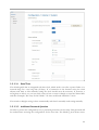
2.21 Connecting the SolarLog1000 Mobile Package
The Mobile package connects the SolarLog1000 with the internet over a mobile phone network.
Additionally to the Mobile Package, you also need a SIM Card from your choice of mobile
phone providers (not included).
2.21.1 Included in delivery: SolarLog1000 Mobile Package
Mobile Modem GPRS
•
RS232 serial cable
•
Power adapter
•
external antenna with 2m connection cable
(a DIN rail is available optionally as an accessory)
•
Connection to SolarLog1000
1.Insert the SIM card into the modem. Press hard with a sharp object on the yellow eject button
on the side of the modem.
2.Screw the external antenna onto the modem. Find a suitable place where the antenna (with
magnetic foot) has a good reception. Possibly check the reception with a normal mobile phone
first. A good reception is important for a reliable data connection.
3.Connect the modem via the RS232 serial cable to the SolarLog1000
4.Plug the RJ11 plug of the power supply into the modem
All other settings can be configured on the SolarLog display. A PC isn't needed.
2.22 Connecting the MT Sensor Box
The SolarLog1000 is thanks to the MT Sensor Box (optional accessory) capable of collecting and
storing environmental data. The environmental data include:
•
Radiation sensor
•
Module temperature
42
Ambient temperature (optional, sensor accessories)
Wind speed (optional, sensor accessories)
This data delivers important key values for yield control and further evaluation/analysis.
•
•
The SolarLog radiation sensor is equipped with a high quality mono-crystalline cell, rugged and
designed for permanent use outdoors (IP65). All components are just screwed on, so that the
assembly can be carried out very quickly. All cables are UV and weather resistant.
Warning: The opening of the sensor is not necessary and would lead to a loss of guarantee.
Currently a maximum of 1 Sensor Box can be attached to the SolarLog1000.
The connection of the Sensor Box to the SolarLog1000 happens via a free RS485 interface,
which can be accessed via the display (Dialogue Config/Initial configuration/Start) and needs to
be set to the "MT Sensor" interface type.
2.22.1 Assembly
Sensor:
The radiation sensor must be fixed parallel, i.e. the same orientation and inclination of the modules on the mounting bolts attached to a mounting rail. The location should be chosen so that
preferably no shading happens.
Module temperature
The module temperature is controlled by an integrated cell-temperature sensor, so that a more
complex assembly on the back of the module isn't necessary.
Outside temperature (optional):
The outside temperature sensor is screwed into the radiation sensor (3pin connection). Screw on
tight. Mount the sensor in a shady place with the wall-mount brackets. The cable must not be
extended.
Wind Speed Sensor (optional):
The wind sensor is screwed into the radiation sensor (2pin connection). Screw on tight. The wind
wheel needs to be fixed above the assembly bracket in a more exposed position. The cable must
not be extended.
2.22.2 Wiring
The connecting cable is 4-wire one and includes the 12V power supply and data line to the SolarLog. No separate power adapter is required. The power cable may be extended (max. 100m), but
it must have the supply voltage of 12V at the end of the cable line. Outdoors, the cable connection needs to be protected accordingly and done a minimum IP54 protection. Note: penetrating
moisture/wetness can cause a short circuit and destroy the Sensor Box and SolarLog.
The 4-wires of the connecting cable should be connected with the green 4-pin plug on the SolarLog (allocation is on the backside of the Sensor):
The wiring is as follows:
RS485 SolarLog
Sensor Box
1
2
3
4
(Data+)
(+12V)
(GND)
(Data-)
Data+ A
+12V
GND
Data- B
(brown)
(red)
(black)
(yellow)
43
2 Installation
The shielding needs to be connected to a potential equalisation.
2.22.3 Initial startup
When the SolarLog1000 is switched on, the Sensor Box also receives electricity. Afterwards, the
Sensor Box needs to be configured to the desired free RS485 interface. That can be done through
the display dialogue (Config/Start Config/Start where you can select the "MT Sensor".
The Sensor Box can be then via the display dialogue "Inverter Detection" integrated into the system, just like any normal inverter can be too.
2.23 Connecting external electricity meters
An external electricity meter can be connected to the SolarLog1000 via the S0-input. An external
three-phase electricity meter of the whole plant can give an exact reference measurement for
example when a solar plant is owned by more than one party, giving accurate interval billing possibilities.
The electricity meter is listed as a virtual inverter on the SolarLog1000. The pulses are placed in a
momentary power value (Pac) and the total income is offset.
Therefore, the SolarLog1000 is capable of monitoring a plant without further connections to
inverters. Especially then, when the installed inverter data protocol is not supported yet. Together
with the radiation sensor from the Sensor Box, the SolarLog can be used as a monitoring device
for such installations.
The S0 port on the external electricity meter needs to be connected to the 6-pin S0 In/Out plugs
as follows:
6
1
SolarLog
1
2
3
bridged
4
5
unused
6
unused
S0
S0+
S0-
The cable length between the electricity meter and SolarLog1000 should not exceed 10m.
44
The pulse factor is set at 1000 pulses/kWh per default, but can be changed on the SolarLog display in the dialogue "Config/Basic/Inverters" on inverter 1.
2.24 Attaching large displays
There are basically 2 different ways to attach large displays to the SolarLog1000:
1. Via RS485
2. Through S0 pulse output
Generally, the RS485 port should be used if the choice exists. The RS485 cable lengths usually go
up to 1000m and the data can be displayed on the SolarLog1000.
The current feed performance can be read through the SO output as a pulse string. The display
must calculate the performance and overall yield by itself.
2.25 RS485/EIA485 wiring
If the RS485 connection is used, one has to take into account that the interface is already in use
by the inverter. The display in general can be looped into the same RS485 line. Basically: As soon
as the RS422 interface is being used (Fronius/Phoenixtec/Sunville) no display can be connected.
Note: Generally, the manufacturer's specifications need to be followed. If the display is looped
into the same line as the inverters, then the display needs to have the interface parameters set
accordingly. Please contact the manufacturer of the display to do this.
Schneider-Display Technology:
3-pin Control cable, 3x 0,5mm²
Display
SolarLog RS485-A/B
brown - A
1
2 (unused)
grey-GND
3
blue-B
4
RiCo Electronic:
To attach the RiCo display via RS485 to the SolarLog, the terminal block 3, Pin 1 and 2 must be
connected. More detailed information available in the manual of the display.
2-pin Control cable, 2x 0,5mm²
Display
SolarLog RS485-A/B
Pin1: Data+
1
2 (unused)
3 (unused)
Pin2: Data4
45
2 Installation
2.26 S0 output wiring
The S0-output can be configured and used in various ways, depending on the wiring of the 6-pin
clamp plug.
6
1
2.26.1 Current controlled S0 output
(e.g. Displays from Schneider Display Technology)
Requires a 2-pin shielded cable, 2x 0,6mm², max. length 100 meters
Observe strictly the manufacturer's data of the display manufacturer.
Display
S0+
S0-
SolarLog S0 In/Out
4
5
6
bridged
2.26.2 Contact controlled S0 output
(e.g. Displays from RiCo Electronic)
Requires a 2-pin shielded cable, 2x 0,6mm², max. length 100 meters
Observe strictly the manufacturer's data of the display manufacturer.
Display
S0S0+
SolarLog S0 In/Out
6
5
2.26.3 Pulse factor
The SolarLog1000 is set by default to 1000 pulses/kWh on the SO output. This value can be
changed on the SolarLog display under the dialogue "System/Large display". The pulse factor
needs to be configured in conjunction with the plant size (kWp).
Plant size kWp
Pulse factor
30 kWp
2000
60 kWp
1000
100 kWp
600
46
150 kWp
400
300 kWp
200
600 kWp
100
Please note that the impulse factor on the SolarLog and the display need to be identical.
2.27 Connecting Relays
The SolarLog1000 has a potential-free control relay which can be switched on in the event of an
alarm or failure. It may be charged with a maximum of 24Volt and 5 amps, so that a 220Volt
load can't be directly connected but rather through another load relay.
The cabling is via a 3-pin connection plug:
1
3
In OFF-state are:
Pin 1-2 open
Pin 2-3 closed
In the ON state (alert/failure active) are:
Pin 1-2 closed
Pin 2-3 open
Typically, PIN1 and PIN2 are used to connect the load relay.
Through the SolarLog display in the dialogue "Config/Advanced/Anti-theft device", you can
easily test the relay.
2.28 Connecting Alarm contacts
The SolarLog1000 has an alarm contact that triggers when the connection is broken. For the wiring on the mounting-rail, a weather-resistant, thin cable should be used, that rips under strain.
The maximum cable length is 1000 meters.
The connection is via a 3-pin connecting plug:
47
2 Installation
1
3
PIN1 and PIN3 must be connected. If the connection is interrupted, the alarm triggers, which
can send a message via the relay an email or SMS.
The SolarLog can test and configure the Alarm feature via the display in the dialogue
"Config/Advanced/Anti-theft device".
2.29 Connection to a PC / Network
The SolarLog1000 is equipped with a standard Ethernet RJ45 network jack, meaning any standard network cable can be connected to it. Speeds of 10Mbit and 100Mbit are supported.
Generally, any PC network technology can be used to connect the SolarLog1000.. The following
technology is available:
1. Direct Cable Connection
2. Connection via a network router
3. Connection through the mains power (PowerLine)
4. Connection via wireless (WLAN / GSM)
Connect the SolarLog1000 now via the Ethernet RJ45 network cable with your network card on
your PC or if available with your network router.
Please note that for a direct connection of the SolarLog1000 to PC a so-called "Crossover" (twisted) network cable needs to be used.
If using the SolarLog PowerLine package, you can connect the SolarLog via the network cable
supplied with the PowerLine plug. Then connect the PC / switch or internet router via the
second PowerLine plug. The two PowerLine plugs will connect automatically with each other and
serve as a "Network cable via the mains power line". The PowerLine plugs should not be connected via a multiple power socket, as other power supplies would disrupt the data quality.
The IP address of the SolarLog can be comfortably configured via the display. This process is
described in the chapter "startup" in the user manual.
48
3
Manual
Once all the cables and accessories has been connected to the SolarLog1000, the unit can be put
into operation, i.e. the configuration can now be carried out.
The SolarLog500 is designed so that the initial configuration can be done without a PC directly
on the screen. Additional settings can be carried out via PC.
startup is particularly easy since all important settings are automatically done one after the other.
Further configuration can still be done later on. Of course, all settings made at the beginning can
be changed later on.
3.1 Touchscreen Display
The SolarLog1000 can be operated comfortably via the built-in Touchscreen. Touchscreen means
that just like the mouse arrow on a typical PC, you can use your finger on the screen to select
things. You just have to "point" with the finger to go to the desired function and select it. The
pressure applied to the screen isn't important. Just press lightly with the tip of your finger on the
desired position or button. If the SolarLog doesn't respond immediately, wait a few seconds and
try again. Under no circumstances press harder on the screen.
Important note: Using a hard sharp object can break the glass area and lead to a loss of guarantee.
The display has touch points everywhere, which means the controls can be spread out everywhere throughout the display. The following image shows an example of where actions can be
triggered.
49
3 Manual
Action buttons
Action Area
Calling the main menu
• Action buttons
Different functions can be called upon, which depending on the dialogue will be different.
• Action Area
Through pressure on the surface, the main menu will be called up where you can then switch
to other dialogues.
There are generally two types of dialogues:
− Graphic dialogue (like above)
− Text dialogue
Graphic dialogues usually have special functions, sometimes even "hidden" areas of action areas
which can't be seen. For example, if you press on a 'Year' while viewing a bar chart of the "Total
Graphic dialogue", you can jump to the individual year's graphic. The bar itself is therefore an
action area.
50
Text dialogues usually serve as configuration dialogues. In these dialogues, there are no action
areas, but only action buttons:
Action buttons
Text dialogues have always got one or more action buttons on the bottom edge of the display.
The left button is always "Menu", the other buttons vary depending on the dialogue. The "next"
button leads you further into sub-dialogues. The number of sub-dialogues if at all can be seen on
the top right of the screen.
The main menu appears at the upper edge of the display:
51
3 Manual
Selecting more
submenu points
If you press anywhere outside
the menu, it will close the menu
again
By pressing the individual menu points, the further sub-menu points are then accessed. Pressing
anywhere outside of the menu buttons will close the menu again.
Text entries via the Touchscreen are made on a so-called "virtual keyboard":
The virtual keyboard if needed appears on the display and you can carry out appropriate entries
just like a normal keyboard. Depending on the type of entry, a numeric keypad or a full alphanumeric keyboard will be shown.
52
3.1.1 Menu Structure Touchscreen Display
The following menu structure gives an overview of the available dialogues on the Touchscreen
display:
Level 1
Level 2
Graphic
Overview
Level 3
Day
Month
Year
Total
Large display
Diagnosis
Messages
Inverter activity log
Alarm contact (anti-theft)
USB
Copy data
Data backup
Copy all data
Input yield data
Input configuration
Firmware Update
Configuration
Start
Initial configuration
Inverter detection
Basis
Network
Plant groups
Inverter
Forecast
Internet
Basic settings
email/SMS
Homepage
Advanced
Plant monitoring
Large display
Alarm contact (anti-theft)
Inverter status monitoring
RS485/EIA485 wireless package
Internal
Data correction
System
Firmware
Language settings
53
3 Manual
3.2 PC display
To operate the SolarLog on the PC, you don't need additional software to be installed. The SolarLog has an integrated web server which contains all the software necessary. All evaluations and
graphical configurations can easily be done on the PC, you only need a web browser.
For operation via web browser, a network connection between the PC and SolarLog1000 is
necessary. The network configuration must first be carried out on the text display.
It is recommended to use the internet browser "Mozilla Firefox" which is available on all major
operating systems.
Generally though, any internet browser can be used. Please activate "Javascript" for use with the
SolarLog1000.
To call up the main dialogue on SolarLog1000, start your internet browser and enter the network
address.
3.2.1 Menu structure PC display
Level 1
Level 2
Yield data
PC Visualization
Level 3
Palm / Pocket PC
Diagnosis
Event log
Degradation
Configuration
Basis
LAN
Plant groups
Inverters order
Inverter
Forecast
Graphic
Advanced
Internet
email
SMS
Export
Fault
Internal
Backup
System
Update
3.3 Initial startup
Once all the cables and accessories has been connected to the SolarLog1000, the unit can be put
into operation, i.e. the configuration can now be carried out.
The SolarLog1000 is designed so that the initial configuration can be done without a PC directly
on the display.
54
However, there are dialogues which are only available via the display (for example inverter detection), or only via a web browser on a PC (for example sorting the display order of the inverters).
Generally, we recommend configuration directly on the display, though dependant on plant size
and knowledge level of the installer, the operation via PC could be easier and possibly faster.
startup is very easy, as all the important dialogues and settings are dealt with automatically one
after the other. Further configuration can still be done later on. Of course, all settings made at
the beginning can be changed later on.
Generally, the startup is divided up as follows:
1.Start configuration
1.Inverter manufacturer details
2.Inverter detection
2.Configuration of the inverters (only connected module performance)
3.Internet configuration (if necessary)
1.Configuration of the Internet access (DSL, modem, wireless)
2.Details of homepage site-access data
3.Test Internet access
4.Other functions (if necessary)
1.Alarm functions
2.Large display
The vast majority of settings are already preconfigured on the SolarLog and don't need to
be changed.
3.3.1 Start configuration
Start first with the details in the "Start configuration":
Select "Config" in the main menu. /Start/Start configuration. This dialogue contains the most
important settings like date and time, network address, as well as the inverters in use.
Please check the date and time. The SolarLog1000 contains a supporting-capacitor that can buffer the time set at the factory over a long period of time. However, the date and time should be
corrected if necessary. The IP address of the SolarLog is also already set, so as to allow faster
55
3 Manual
access per PC onto the SolarLog. The address can also be configured later, see chapter "Connecting to the PC/Network". If the SolarLog is attached to an Internet router, the network address
will be set automatically.
In the next 3 dialogues, the attached inverters can be configured. For every interface type, i.e.
RS485-A, RS485/422-B and S0 input, the corresponding inverter manufacturers are displayed.
Identical OEM devices are selected according to the original manufacturer, as the data telegrams
are generally identical.
Finally, you can spring directly into the dialogue "Inverter detection".
Bluetooth option:
The SolarLog1000 can be factory ordered with the Bluetooth Option so that certain inverter
models from SMA can be attached via Bluetooth. In this case the the appropriate selection
appears at the Start configuration in dialogue "2/5". If Bluetooth is selected, then "SMA" is automatically preset.
Warning: The use of the Bluetooth interface automatically disables the RS485-A interface. Only
RS485-B can be used additionally.
3.3.2 Inverter detection
The Inverter detection scans all active interfaces, to identify the amount and type if necessary of
inverters attached. The detection may take some time, especially with SMA and Sputnik/SolarMax. The display however shows the status and the number of identified inverters. By clicking
the "Finish" button, the scan can be shortened if all inverters are already detected.
Note: The maximum number of 100 inverters per SolarLog depends on the length of data cable
and on the inverter manufacturers being used. SMA allow for example a maximum of 50 inverters per interface, Kaco allows the addressing of 32 inverters on a single interface.
56
If the inverter configuration is changed later on, the inverter detection has also to be repeated.
The SolarLog automatically recognizes that a post-detection is required and formats the existing
data accordingly. This process may take a long time, depending on the existing data and number
of inverters. During this time, the SolarLog shouldn't be interrupted or shut down, as a loss of
data would result. Therefore it is generally recommended before a post-detection is carried out,
that a full data backup is carried out onto a USB stick or via the Web browser onto a hard drive.
Check after detection the number of inverters. If not all inverters were detected, please check the
wiring and settings on the inverters. Depending on the manufacturer there needs to be a change
in the address number or the RS485 interface needs to be activated on the inverter.
Once you have identified the inverter, the SolarLog begins immediately with data recording.
There are no restrictions regarding data recording and configuration. The SolarLog offers you to
continue with the configuration of the inverters, which is also recommended.
3.3.3 Inverter Configuration
The inverter configuration appears at first to be very extensive. However, only the attached generator power details need to be modified, all other parameters for monitoring exist already with
meaningful default values and can therefore normally be left unchanged. Also the Sensor Box
and the S0 input is configured as an inverter. Here some special details are necessary, which are
accessible via the "Next" button.
Depending on the inverter manufacturer and type of inverter, the input values can vary.
Number
Here, additional inverters can be selected from a list.
New number
(Only visible for certain inverter manufacturers)
Since SMA and Danfoss inverters have no address number adjustable via the
inverter display, the inverters are sorted according to their serial numbers,
which is more or less randomly done, and may not correspond to the addressing desired. Therefore, the current position can be changed to another one.
Note: It is recommended to carry out this change immediately after inverter
detection, since already logged data can not be transferred to the new position.
If a larger number of inverters needs to be reordered, the dialogue "Inverter
order" via the web interface on the PC should be used.
Device
number
name/serial Differs depending on the inverter manufacturer.
Product label
Here any label can be chosen, which is shown on the display dialogue or on the
PC.
57
3 Manual
In dialogue 2, the connected module performance can be entered. Depending on the type of the
inverter, the total performance or the string performance can be configured. Please enter the
exact performance data here without errors, since these values are used to monitor the plant performance.
Module field
Connected
power
Via the Module field number, you can order together similar strings/inverters.
Only strings/inverters with the same module field number are compared
against each other during the plant monitoring.
Example: 4 inverters aligned East connected and 3 inverters on modules
aligned West. The module field number The "East Inverter" should now be "1"
and the "West inverter" should be "2". These parameters are important for performance comparison of the inverters to each other.
module Here, for every inverter or string (only for Multi-String inverters), the module's
exact power total must be specified.
At 28 x 160 Watt modules = 4480
Product label
The String name, which appears on the homepage or PC (only for Multi-String
inverters)
In Dialogue 3 and the following dialogues, the data for the system monitoring is configured. The
SolarLog already has useful predefined values preset, so that nothing needs to be changed here at
the startup phase.
You should therefore press "Save". Then configure all the inverters one after the other in order as
described above.
This completes the normal setup of the inverter. The SolarLog now records the data of the
inverter and monitors the plant.
3.4 Display menu navigation
Operating the SolarLog via the display happens through many dialogues, which can be selected
via the main menu. During the development of the SolarLog, a lot of value was placed on being
able to completely operate and configure the SolarLog without the use of a PC.
3.4.1 Graphic
3.4.1.1 Overview
This dialogue provides an overview of the date, time, detected inverters and accessories, as well
as the current day/total values and CO2 savings.
58
3.4.1.2 Day graphic
The day graphic show the performance values (Pac) of the inverter as a curve. The scaling of the
y-axis calculates automatically from the total of the displayed inverters. The hours displayed on
the x-axis can be configured separately for every month.
Below that the legend shows the most important parameters as a numerical value:
Pac
Current feed-in power (Pac)
Pdc
Current module power (Pdc)
Efficiency
Efficiency according to the formulae Pac/Pdc x 100
Energy
Accumulated Days Yield in kWh
Specific Yield
Specific energy = Day Yield kWh / Plant size kWp
Pmax
Highest reached performance value in 5-minute averaged values
The status displays the current inverter status and error codes. Inverters with the same status are
grouped together. The status and error text is manufacturer specific and should be in the manufacturer's user manual. The status "MPP" means "Maximum Power Point" and means that electricity is being fed in.
"Offline" means that the inverters are in night-time mode, so are off.
By using the buttons at the top of the screen, you can browse the day's date using "previous or
next". Pressing on the date always changes you to the present day. Pressing on the bottom screen
area opens the main menu.
Pressing the middle button "Day graphic" opens a submenu:
Via this submenu, further options are available. The options that appear depend on whether a
Sensor Box is attached or not. The selection boxes in the rectangle fields are parameters, which
additionally to the power curve can be shown on a second y-axis. Only 1 parameter can be selec-
59
3 Manual
ted, otherwise the overview gets lost (several parameters in the web view can also be displayed in
colour).
Inverter selection
To select the inverters in the day view, you can select and control them here. Every
inverter selected or deselected, or "All inverters" selects all inverters at once.
In this example, the inverters 2, 3, 6 and 7 have been selected for the calculation of
the graphic and the legend.
If groups have been defined, then the groups appear first and then the next step
leads to the selection of the inverters inside the groups.
Using this technique, you have access to all or only a certain selection of inverters.
Yield line
A yield line appears in the graphic together with the day's target value.
Udc
Here the DC voltage history is shown. If several or all inverters in the plant are
selected, the averaged voltage line is shown.
60
Temp. Inverter
Sun
sensor
Here the inside temperature of the inverter is displayed. Not all inverters deliver
these data values (for example SMA and Fronius don't)
Radiation The Sun radiation sensor provides a standard reference value for current sunlight.
The value is directly comparable to the plant DC power converted to 1kWh/kWp.
The graphic shows the reference value as a hatched area, within which the actual
DC power should be at.
In the example we see that the DC power before noon was below the possible theoretical performance. In this case, it's due to shading, it's not always a fault or a
defect at the plant.
Temp. Module
The module temperature is an important parameter regarding module efficiency.
61
3 Manual
Temp. Outside
Wind
The outside temperature is an optional sensor, which is available as an accessory to
the Sensor Box.
3.4.1.3 Month graphic
The month's graphic shows the daily values. Again here, the y-scaling is automatically calculated
from the selected inverters.
You can navigate like the day graphic with the buttons at the top of the screen. The choice and
selection of the inverter can be done via the "Month's graphic" button.
If one day's bar is clicked, it will change to the corresponding date's day graphic. Because the
bars are relatively thin, you sometimes hit the wrong day, but you can quickly change that to the
correct day with the "Previous/Next" buttons.
62
The legend shows the main parameters as a numerical value:
Yield target
The SolarLog calculates for every month a target yield, that in turn determines the year's
desired yield/earnings.
Actual
yield/Target
yield
Displays the generated target/actual yield in percent
Average yield
The average of all days in the month
Actual yield
The actual month's yield in kWh
Specific Yield
Specific energy = Month's yield kWh/Plant size kWp
Maximum yield Highest day's yield in the month
3.4.1.4 Year graphic
The year's graphic shows the monthly values. Again here, the y-scaling is automatically calculated
from the selected inverters.
You can navigate like the day graphic with the buttons at the top of the screen. The choice and
selection of the inverter can be done via the "Year's graphic" button.
If one month's bar is clicked, it will change to the corresponding date's month graphic.
The legend shows the main parameters as a numerical value:
Yield target
The annual target value is determined by the year's desired yield via the dialogue "Forecast"
Actual
yield/Target
yield
Displays the generated target/actual yield in percent
Average yield
The average of all months in the year
Actual yield
The actual year's yield in kWh
Specific Yield
Specific energy = Year's Yield kWh / Plant size kWp
Maximum yield Highest month's yield in the year
63
3 Manual
3.4.1.5 Total graphic
The overall graphic shows the stored yearly values. A total of up to 6 years can be shown within
one graphic. From 7 years onwards, you can browse via the previous/next button to other years.
You can navigate like the day graphic with the buttons at the top of the screen. The choice and
selection of the inverters can be done via the "Total graphic" button.
If one years bar is clicked, it will change to the corresponding year's graphic.
The legend shows the main parameters as a numerical value:
CO2
The total CO3 value saved
Average yield
The average value of all years
Minimum yield Lowest annual yield
Actual yield
The total yield
Specific Yield
Specific energy = Total yield kWh / Plant size kWp
Maximum yield Highest year's yield
3.4.2 Diagnosis
Under diagnosis you can query in detail the plant's condition.
3.4.2.1 Messages
The SolarLog generates messages depending on configuration for errors and faults, or just to give you the
current day's yield. Each message can be sent as an email or SMS. In addition, all messages are stored temporarily in memory and are available on the display for retrieval. The last 50 messages can be retrieved.
Furthermore calling the messages list acknowledges/confirms the pulled relay, which is connected into
the plant monitoring. Example:
64
It's part of the inverter configuration, that an inverter breakdown activates the relay. If an inverter breaks
down now, the relay trips. It remains tripped until you pull up the dialogue "Messages". This acknowledges/confirms the error, so to speak.
Since all messages are usually sent per email, the corresponding message is also stored in the messages list.
That gives you the ability later on, to find out the reason why the relay was tripped.
The messages list saves:
• Date and time of the incident
• Incident type The following incident types:
"Day's income", "Performance monitoring", Inverter status/faults", "Inverter offline", "Alarm contact"
• Message type "email", "SMS" or "---" (nothing sent)
• Delivery status.
„OK“ Sent
„#x“ x = Number of failed transfer attempts. After 4 attempts appears "NOK"
3.4.2.2 Inverters event log
The event log records all status changes to the inverter in a separate protocol. Every 15 seconds
(depending on the number and type of the inverter sometimes even longer), the status and error
codes are read from the inverters. If there's a change, it gets saved in the log. Every inverter has
200 memory slots available. The current status is always at the very top of the list in dialogue
Page 1.
If an error occurs, then the text "Err" blinks. Some inverter manufacturers do not provide extra
error codes in their data telegrams, here the errors are "packed" as status code. In this case, no
"Err" is displayed.
Error codes are per default so configured in the plant monitoring, that an email gets sent. Therefore, critical messages also appear in the dialogue "Diagnose/messages".
65
3 Manual
3.4.2.3 Alarm contact (anti-theft)
The SolarLog1000 constantly monitors its internal alarm contact. Once this has been interrupted
the alarm is triggered. What happens here can be configured in the dialogue "Config/Advanced/
Alarm contact" (notification by email/SMS/relay).
Once the alarm has triggered, it remains active for a maximum of 20 minutes, then it automatically gets cleared. You can manually clear the alarm at any time or even completely reset it. You
should only carry out a reset, if the cause of the alarm has been dealt with, otherwise it will trig ger immediately afterwards again.
3.4.3 USB
The SolarLog contains a USB interface, which every USB compatible USB stick can be connected. The maximum memory size shouldn't exceed 2GByte.
Note: A PC can't be connected to this USB interface.
3.4.3.1 Copy data
Here you can copy all data from the SolarLog to a USB stick. The unique thing about it is, you
can view all the data offline on a PC afterwards, i.e. without a direct network connection you can
view the data. The visualization is done using the Web browser, no software has to be installed
on the PC
Copying the data always gives you the data for the day curves of the last 31 days. If a complete
record is desired, you should copy at least once this time period onto the USB stick. The old data
of course will be kept. A USB stick with 512 MB memory is sufficient for many years of data
storage.
After saving the data, the USB stick can be plugged into the PC. After a brief pause, a window
will automatically open under Windows.
66
Please select "Open folder, to see files".
If no window opens, then open the file manager "Explorer" and select the USB stick drive.
There you will see the file "index.htm" and also the folder "SL1000" which contains all the data.
Please double-click or open the "index.htm". This opens the visualization, which is described on
page 105
3.4.3.2 Data backup
67
3 Manual
The data backup can be done any time onto a USB stick or back to the USB stick. All data is
saved (Day curves max. 60 days), i.e. the configuration and measurement data. When restoring
the data, the measurement data or the configuration can be selected individually.
3.4.3.3 Firmware Update
Firmware updates can also be carried out via the USB stick. Just download the latest firmware
from www.solare-datensysteme.de and save to the main directory on the USB stick.
The SolarLog has the possibility of taking care of firmware updates automatically. This function
can be activated via the display dialogue "Config/Internal/Firmware", and is already setup with
DSL connections.
3.4.4 Configuration
The following describes the configuration dialogues presented in the order that they appear.
3.4.4.1 Initial configuration
The initial configuration contains the most important settings that need to be made, before the
data logging and monitoring can begin.
After the very first start of the SolarLog1000, dialogue 1 is opened, later you have to navigate
here manually via the main menu. The time zone GMT +1 is setup by default, which is suitable
for all countries in Central Europe.
68
The time (clock) is important, which is already setup from the factory by default, but after prolonged storage can be lost. Then a random value is there, that has to be corrected.
The IP address is 192.168.178.49 by factory default and can be modified here to a network
address, which suits a local network. Saving a change in the network address causes the SolarLog
to restart . Generally the IP address only needs changing or controlled, if the SolarLog1000 is
attached to a router or a PC.
Furthermore, it's possible to get a network address automatically. That is only possible if the SolarLog is attached to an internet router, which has this function ("DHCP"). After saving and the
associated restart, the new IP address will be shown accordingly. The SolarLog can now be
accessed via this address and has automatic access to the internet.
In dialogue 2, you can choose the inverter manufacturer, that is attached via the RS485-A interface. Note that the MT Sensor Box is also treated like an inverter and therefore runs as type "MT
Sensor".
In dialogue 3, the RS485/422-B interface is defined, here you can also set the "Fronius" inverter.
69
3 Manual
Here is the possibility to activate the electricity meter attached to the SO input. This setting is
important, as the electricity meter is treated/managed as a virtual "Inverter" on the SolarLog1000. An "electricity meter inverter" has subsequently always the number 1, all other "real"
inverters follow thereafter.
Since the initial configuration is a quick guide into a functional and ready system, you can now go
directly to the dialogue "Inverter detection". All previously entered data is automatically saved.
3.4.4.2 Inverter detection
The "Inverter detection" is used on SolarLog1000 to detect all attached inverters and to sort the
assigned addresses. Via the dialogue "Start configuration" you have to define which interfaces are
occupied by which inverters. Number and type of devices are now automatically recorded here.
Based on the number and type of devices, the memory on the SolarLog is optimally divided in
order to maximise long-term data storage. If the number of inverters is changed later on, the
internal database has to be reformatted, and depending on the data already stored can be quite a
complex and lengthy process.
The initial detection looks like the following dialogue:
Now press "Start" and it changes into the overview:
70
Every interface is shown with the predefined inverter-type, and everything is examined in turn.
This process can be relatively long, such as when Sputnik/SolarMax searches through a 253
address range.
Important: For the inverter detection, all inverters need to be active. The detection cannot be
carried out in darkness.
After detection, please check the number of found inverters. If one is missing, you should control the settings on the inverter and check cabling/wiring (see Installations Guide) and repeat the
detection process again. Only when all inverters are successfully detected should you proceed.
If no inverters are detected, this also will be displayed and also in this case, the detection has to
be repeated.
Once detection has been completed successfully, you'll be asked if you want to continue to the
"Inverter configuration". You should confirm with "Yes".
3.4.4.3 Inverter Configuration
The inverter configuration consists of 5 sub-dialogues, but only the first 2 are important for the
initial configuration. The other settings apply to the plant monitoring and the graphic scaling,
which are all set to "good" values by default. Generally you don't have to make any changes.
All dialogues relate always to a single inverter. Which inverter is currently being configured is
shown in dialogue 1 above at „Number“. This number can be changed by pressing on it. In this
case a list of all inverters is displayed which you can select from.
The "number" is the internal position under which the inverter is managed. The number reflects
again which address the inverter was assigned on the display. Inverters without an address
assigned, e.g. SMS or Kyocera/PowerLynx are more or less randomly displayed or sorted according to serial number. This order can and should be changed with the help of the function "New
number" to a real and desired address. This change should take place immediately after the
71
3 Manual
inverter detection has been done, as the associated data can't be applied to the new number. The
field "New number" is only visible to inverter manufacturers, where the address number is not
adjustable.
Device name and address/serial number are purely display fields and can't be changed.
The label should be changed or at least checked. There should be a clear, speakable text chosen
for the inverter, as this text is used as a label in a lot of selection lists and graphics.
In dialogue 2, the connected inverters 'generator power' needs to be configured. This information is very important in terms of correct system monitoring. Please determine and enter their
values meticulously and error-free.
Dialogue for multi-string inverters (e.g. SMA SB5000TL, Danfoss or Power-One, depending on
the model):
Dialogue for standard inverters (in which single strings are internally switched together):
Module field
Via the "Module field", the same strings for system monitoring are merged together and
monitored together. For a roof with the same modules, same orientation and identical
roof slope, all strings are assigned the Module field "1". If even more inverters are con
nected, which have a different orientated roof, these strings receive the module field
number "2" and so on.
Connected module power
This value is needed to facilitate the comparison between the different inverter's perform
ance and to offset their values against one another.
The other dialogues are already preconfigured and don't normally need to be changed. A description of the fields is available on page 83 in the configuration via web browser.
72
3.4.4.4 Network Settings
The network settings are always needed to be configured when
you want to access the SolarLog1000 on a PC via a network.
for those wanting to connect the SolarLog1000 through a router to the Internet.
for those wanted to connect an analogue modem or GPRS modem for remote monitoring
on the SolarLog.
3.4.4.4.1 Dialogue 1 – Basic settings
Here you can configure the IP address and subnet mask. The factory default address
is192.168.178.49 and needs to be adapted so that access via a PC is possible. An exact description
on how to do this is on page.
Then you define the appropriate internet access for you.
„Network router“ means that a router needs to be attached to the network interface of the SolarLog1000. This router takes over the entire dial-up and data transfer into the internet. In general,
DSL routers are used, but also increasingly routers attached to a TV cable modem. It's important
that the dial-in is always possible for the SolarLog. The router should not be turned off, otherwise proper notifications won't get through in the case of faults/breakdowns or the homepage
won't have the correct data.
„Analogue modem is valid for a telephone connection.
„GPRS modem means a connection to the internet via a mobile phone network.
73
3 Manual
3.4.4.4.2 Dialogue 2 – Network Router
The attached internet router has its own IP address, which must be entered under "Gateway".
How to find the IP address of the router is found and described on page .
In some networks, especially at companies, the DNS server has a separate address and not
identical to the Internet router (Gateway). In this case, a separate DNS can be configured.
3.4.4.4.3 Dialogue 3 – Analogue Modem
If a telephone line is available, the SolarLog1000 can with the help of the SolarLog1000 Modem
Package gain access to the Internet. This is always necessary when you want to receive information remotely per email, SMS or on the homepage.
The internet-by-call provider Arcor has already been setup by default, complete with dial-in number, Username and password. The cost is 1 cent/minute, but are also time-dependent. Of course,
any Internet-by-call provider can be used here.
Note: Solare Datensysteme Ltd. is not liable for costs resulting from data connections.
On some telephone systems, it's necessary that before the actual telephone number a "0" must be
pre-dialled. This setting can also be made here. By default, you can hear the dialling process of
the modem, which gives you a good test function until the connection has been established.
Later, the dial tone will be turned off.
74
Problems with the internet connection are best tested with a conventional telephone, whether the
telephone line works and is active. If "0" a as prefix is to be used, this then can be tested easily
and fast.
When using an analogue modem, the SolarLog1000 is generally capable of a dial-in connection.
That means that the SolarLog can be dialled into from "outside" using a PC and modem. The
SolarLog1000 recognizes this and establishes a data connection. This process is described on
page 113.
The standard password is "solarlog" which can and should be changed here.
3.4.4.4.4 Dialogue 4 – GPRS Modem
In many cases in which no DSL or telephone line is available, the connection to the Internet via a
mobile phone network is the only option available. From a cost perspective, there are many very
cheap data connection possibilities with providers like the mobile phone provider "Simyo" in
Germany. Monthly costs of under 5 Euros are possible, but of course depend on the plant size
and the number of transfers per day.
The configuration is very easy, it needs only a "APN" (Access Point Name), a Username and
password. The factory default has "Simyo" already preconfigured. If the GPRS modem with a
SIM card is used, no settings have to be changed.
Note: Many SIM cards need to have the data option activated via a telephone call first.
The following APN/User settings are set for known German mobile phone providers:
Simyo / Eplus
O2
Vodafone
T-Mobile
Used Network
EPlus
Eplus + D1
D2
D1
APN
internet.eplus.de
surfo2
web.vodafone.de
internet.t-mobile
User
eplus
[leave empty]
[leave empty]
t-mobile
Password
eplus
[leave empty]
[leave empty]
tm
(All infos are for Germany and without any guarantee for its correctness)
Please also enter a valid PIN code.
Then save the settings and go to the "Test" button to check the signal strength of the GPRS connection. The connection should at least be "Good", otherwise no secure and permanent connection can be guaranteed.
Note to "User" and "Password".
If GPRS provider recommends that the 'Username' and 'password' be left 'empty', sometimes
something needs to be entered for a successful data connection to be established.
75
3 Manual
3.4.5 Internet
Via the settings "Internet", all information regarding the internet-server being used and the
homepage should be made.
3.4.5.1 Basic settings
Here the access data for the internet connection is to be entered.
Warning! There are two different types of Internet connections:
1. Solar Engineer Portal/SolarLog Portal
This portal costs money to use and offers in addition to the visualization of the plant, a
host of other evaluation tools and monitoring functions for the Solar Engineer.
2. SolarLog homepage
The homepage is free and is meant as an entry to Internet monitoring. Registration must
be done via „www.solarlog-home.de“, in order to receive the necessary access
data/information.
3.4.5.2 email/SMS
Here you can activate the email and SMS function, up to 2 email addresses for notifications can
be entered and one SMS mobile phone number as well.
Note: The SMS function costs to use. For test purposes, 3 free SMS's are available after registration, then afterwards an SMS quota can be purchased via „www.solarlog-home.de / SMS“.
Through the last sub-dialogue, you can send a test message, which needs to be successfully sent
at least once.
3.4.5.3 Homepage
Here you can set the interval for updating the Data export to the Internet. "Daily" is set by
default, but depending on the type and costs to make the internet connection, you can reduce
this time down to a minimum of 10 minutes.
In the other sub-dialogues, you define a plant description for the homepage, as well as triggering
a connection test.
76
3.4.6 Advanced
The advanced functions are generally rarely used and therefore found in this separate menu
point. The following items are available:
• Plant monitoring
• Large display
• Alarm contact (Anti-theft security)
• RS485/EIA485 wireless package
3.4.6.1 Plant monitoring
These helpful settings manage centrally which disturbances/faults trigger which alarms. It's
recommended as a final configuration step to set this parameter.
LED „E“: In the case of an fault/disturbance, the LED "E" begins to blink. This feature is useful, when the SolarLog is to be used without an Internet connection, but the plant owners still
want to have a simple way of monitoring the plant.
„Relay“: In the case of a fault/disturbance, the potential-free contact (relay) closes. This feature
for example can activate an alarm light/beacon, to give a quick visual control - even without
Internet connectivity.
3.4.6.2 Large display
There are currently 3 "classic" large displays supported:
• Schneider Display Technology
• RiCo Electronic
• HvG Hard & Software Engineering
These displays can be attached via the RS485 bus or even on the S0 pulse input. If the RS485
bus is already occupied by an inverter, a display can still be looped parallel into the data bus.
Observe strictly the instructions from the display manufacturer regarding the wiring and possible
pre-configuration.
77
3 Manual
3.4.6.3 RS485/EIA485 wireless package
The RS485 wireless/radio package is an optional accessory to connect remote inverters, which
were difficult to attach per cable to the SolarLog. Since wireless connections never work 100%
predictably, there is a test function to examine the connection. It's important that the RS485
interface to be tested is configured to the corresponding inverter via the dialogue "Config/Start/
Start Config" and that the radio modules are set to the corresponding transmission speed of the
inverter. For the test, there's an appropriate test adapter available for the wireless package. Please
refer to the manual regarding the wireless package settings.
3.4.7 Internal
The dialogues in the "internal" area are rarely needed, usually only for the initial installation.
The following items are available:
• Data correction
• System settings
• Firmware
• Language settings
3.4.7.1 System
The system functions control the backlight on the display, i.e. the On and Off time, plus a dimmer function for the display when it's not being used over a longer period.
The "Slide show" function switches, similar to a screen-saver, after a period of time between the
individual graphic functions.
Furthermore, the display can be protected against illegal access via a PIN code protection.
In the last sub-dialogue, the SolarLog can be returned to factory settings.
3.5 Configuration via PC
The configuration can alternatively be carried out on a PC via a web browser (e.g. Internet
Explorer).
Note: Not all functions, that are configurable on the display are available on the web interface.
Generally, all functions required for a unit installation, e.g. inverter detection can only be carried
out on the display.
To access the configurations dialogue, please give in the network address of the SolarLog.
78
Note:The address above only serves as an example. Please use instead the network address that
you entered manually on the display or the address that was displayed during an "Automatic
detection".
The main menu of the SolarLog1000 now appears:
Please choose at the top right "Configuration".
3.5.1 Basic Configuration
The basic configuration includes the most important settings. If used without an internet connection, these settings are usually sufficient.
3.5.1.1 LAN - Network Settings
The network settings are usually set on the display and don't normally need to be changed anymore.
79
3 Manual
3.5.1.1.1 Internet access
Please check here which way SolarLog1000 is connected to the internet. Depending on the settings, various options appear at the bottom area of the screen.
If the network router is selected, the SolarLog directs all internet-related data via the network
interface to the Gateway address. The router there is responsible for the correct delivery of data.
Note: The configuration of the network settings through your web browser is identical to the
operation directly on the display.
Saving the settings restarts the SolarLog1000, so that the changes to the network configuration
takes immediate effect.
3.5.1.2 Plant groups
Since the SolarLog can manage many inverters at once, it's necessary to group the individual
inverters into inverter groups. These plant groups are found then in all inverter dialogue selections, which strengthens the overview immensely. Of course it's still possible to select a subselection and then the individual inverters, e.g. for a detailed view of the data.
80
For each plant group, an individual feed-in tariff can be set, as well as the year's target value. That
makes also plant groups ideal for covering plant expansions, etc. A plant with originally 5 inverters and 30 kWp from 2004, can be expanded in 2007 with a further 3 inverters and 20 kWp, can
also be comfortably managed on SolarLog1000 as separate groups. Feed-in tariffs and the year's
targets can be configured in the dialogue "Forecast", currently possible only via the display directly.
Each plant group can be displayed onto its own large display.
Up to 10 plant groups can be set, with up to 15 inverters per group. Via the Add and Remove
buttons, you can easily assign individual inverters or remove them from a group.
After saving the changes, the settings are immediately active.
3.5.1.3 Inverters order
The order of the inverters is established during the detection phase and is normally sorted by
serial number and communication address. Should the order be changed in the SolarLog, this can
happen easily in this dialogue.
81
3 Manual
On the left side the inverters are listed in the old order, with the current position, the inverter
name and serial number/address number. On the right side, the order can be changed by clicking
on "Add".
The inverter order can only be reordered within a data interface. An inverter, which is
connected via the S0 input or Bluetooth, can't be swapped therefore with an RS485-B
inverter interface.
The change of order applies also to the data within the SolarLog. Therefore there are 3 ways to
reorganize your data accordingly:
1. Leave data unchanged
Was there inverters exchanged due to faults and then via inverter detection newly detec
ted, the new order may differ to the previous one. Therefore, it is absolutely necessary to
configure the new order in this dialogue. However, the data doesn't have to be reordered
– nothing has changed from the perspective of the Data-logger.
2. Reorganize data to a new position
Was the plant expanded, or should the data on the existing plant be resorted, it is import
ant that the data to the inverters also be reordered. If that's not done, there's going to be
a real "data salad" after saving the new order.
The reorganization of the data can take some time depending on the amount of data
already recorded. This process should not be cancelled under any circumstances!
3. Erase all data
If the plant is being setup afresh, this point should definitely be chosen. This deletes the
existing (few) data and SolarLog can begin recording to a clean database.
82
3.5.1.4 Inverter
In this dialogue, all the relevant data from the inverters is stored.
The device name and serial number is read from SMA devices and various other manufacturers
automatically. On other inverters, the communication address will be displayed.
Please check if all inverters have been correctly recognized. Each inverter is uniquely identified
by its serial number.
The inverters are always sorted by the serial number or communication address. If the order is to
be changed, this can be changed through the dialogue "Inverter order". Please note that the
ordering should be carried out immediately after inverter detection.
3.5.1.4.1 Connected generator power
The connected module power on the inverter in Wp. The total power can be calculated from the
'module power' x 'number of modules' (together at each inverter, not the entire plant)
3.5.1.4.2 Pac correction factor
When the electricity yields displayed on the inverter display is compared with the calibrated electricity meter, you'll notice a discrepancy. Either the inverter shows too much or too little. In order
to balance out this difference, you can define a correction factor here.
All yield data is saved internally without the correction factor, it's only at data output that the
factor is offset. This gives the freedom for the factor to be applied at any time later on.
The formula for calculating the correction factor is:
Yield electricity meter / Yield inverter x 1000
83
3 Manual
If the inverter has no display, you have to leave the correction factor at 1000, so that after about
1 week a factor can be determined.
3.5.1.4.3 Product label
Short description of the inverter, in cases of non-multi-string inverters possibly the location of
the connected modules.
3.5.1.4.4 Monitoring
The monitoring of individual inverters, with its strings and modules attached are an important
function of the SolarLog1000. Malfunctions can be reported by email or SMS.
Monitoring and recognition:
1.Breakdown of inverter
2.Performance drop of a module field
The monitoring is based on the constant performance comparison of all inverters including the
single strings on multi-string inverters. If the actual performance goes below a certain tolerance
from the desired performance, after a selectable delay a notification will be triggered.
Each string attached is assigned to a module field. Module fields are divided according to the
same type of solar module, module slope and module orientation. If a plant has all the same
84
modules from the same type and same orientation, then only a single module, e.g. "1" is defined.
Unused strings needs to turned off using "0".
More module fields need to be defined if inverters have differing orientations.
Ideally, each field consists of at least two individual strings, which are capable of mutually monitoring each other.
Example:
A plant with 23.6 kWp is divided into 3x SMA SB5000TL, 2x SMA SB2500.
Which are located on a barn roof 18 kWp with 30° slope, 20° South-East deviation, and on an
adjacent garage 5 kWp, elevated, 32° inclination, 0° South deviation
Location
Inverter
String performance
Module field
Barn
1.SB5000TL
2000
1
Barn
1.SB5000TL
2000
1
Barn
1.SB5000TL
2200
1
Barn
2.SB5000TL
2000
1
Barn
2.SB5000TL
2000
1
Barn
2.SB5000TL
2200
1
Barn
3.SB5000TL
2000
1
Barn
3.SB5000TL
2000
1
Barn
3.SB5000TL
2200
1
Garage
1.SB2500
2500
2
Garage
2.SB2500
2500
2
All connected strings can mutually monitor each other, the strings from module field-1 several
times, both strings from module field-2 mutually monitor each other.
If a single module dips in performance, the string performance will fall in spite of the same sun
radiation conditions and be recognized and reported.
The performance comparison is always reliable even in cloudy weather. The only important thing
is that all modules are not over shadowed. Therefore, a monitoring period can be set in the configuration to guarantee that no shading occurs.
Since the performance measurement in inverters is very inaccurate below a certain threshold, a
minimum percentage can be set under which the monitoring is suspended.
If snow covers the units, it can also lead to errors in the reporting. These are messages from the
performance comparison, when part-coverage happens, or breakdown messages when the
inverter no longer turns on due to snow coverage.
There are two approaches to minimize this problem:
1.The minimum percent value from which performance monitoring begins should be chosen
as high as possible, e.g. 30%.. With a generator power of 4500 Wp, the performance monitoring first begins at 1350 Watts. Partly shaded modules pull down the unshaded module's performance so much that you seldom or never reach the required 1350 Watt. Thereby this
solves the problem for partial coverage.
85
3 Manual
2.Failure messages always occur when the inverters are not working or offline during the preconfigured unshaded times. It is assumed that a defect has occurred. That means that even
complete snow cover would be reported as a breakdown. To solve this problem, there is an
indicator for snow cover. If this is set, no failure messages are given if all inverters are offline.
The fact that all the installed inverters are broken is possible (e.g. after lightning), but rather
unlikely. So if the indicator is set, it is assumed that the inverters do not work merely because
the modules are completely covered by snow. The indication is also dependent on the current
date. Only between early November and late April will it be considered. Outside this period,
so in Spring, Summer and Autumn, it is automatically disabled. Then, the monitoring works
as usual, and reports also a complete failure of all inverters.
The "Fault duration" indicates how long a fault is continuously sent before it is recognized as a
"breakdown". The minimum fault duration is 5 minutes, but should actually be even longer.
To prevent too many disruptions being reported too often, a maximum number of messages per
day can be defined.
3.5.1.4.5 Graphic Scaling
Normally nothing needs to be changed here, as the SolorLog calculates the generator power values input automatically. But, of course, these values can be changed to suit your needs.
For each period (daily value, monthly value, annual value, total) the maximum value in kW can be
entered. (except for day).
3.5.1.5 Forecast
The forecast is used in the current year to provide insight as to whether the plant will reach the
desired annual yield or not.
In addition, a percentage value is allocated each month from the "German Yield Statistics" of
recent years.
Of course you can never know how the summer will be and if one has a full month "of hail",
but in general, the annual forecast in September is already amazingly accurate.
The SolarLog1000 always calculates the target value that accumulates daily. That means at the
beginning of the month not the entire months target is demanded, but only the days already
passed and current days. The SolarLog forecast takes into account the income of all previous
years and can account for local weather events (e.g., mostly snow in December, etc.).
86
3.5.1.5.1 Plant size
Please enter your size in plant Watt peak here.
3.5.1.5.2 Feed-in tariff
Please enter here the feed-in tariff value here. This factor calculates the yield in euro in the visualization.
3.5.1.5.3 Annual target
Here the desired year's target is entered in kWh/kWp.
3.5.1.5.4 Monthly share
Your monthly shares must in total be 100%. You can also adjust the values to suit your local conditions accordingly.
As a rule though, you shouldn't have to change anything.
3.5.1.6 Graphic
The graphical view is determined by a division of the X-and Y-axis.
On the X-axis is the time lapse as opposed to measurement value on the Y-axis.
87
3 Manual
For the day view, it's necessary to define for every month the day's beginning and end, so as to
prevent the 'data begin' or 'data end' being "swallowed" in the display.
Note: The SolarLog1000 works regardless of this setting and collects data as soon as the inverter
starts delivering data and stops when the inverter is shut down at night.
Thus, the two upper input lines are assigned to the start of the day, and the bottom two rows of
data to the end of the day.
Changes don't normally need to be made.
3.5.2 Advanced
Under "Advanced Configuration", the Internet-related functionality in particular is found. If the
SolarLog1000 doesn't have an Internet router connected, this configuration point can be skipped.
It is in any case recommended that the SolarLog be connected to the Internet, at least to ensure
the automatic notifications via email/SMS.
3.5.2.1 Internet
Through this dialogue, the homepage views data can be configured.
Similarly, the Online Banner may be defined according to one's own wishes and text .
88
More on this in the chapter "Homepage"
3.5.2.2 email
The SolarLog1000 includes an email program which can send messages in certain situations.
These are:
• Overview day's yield
• Inverter faults
• Inverter failure
• Deviation of target performance
89
3 Manual
The settings in this dialogue are used both as a basic configuration for sending emails in general,
as well as a configuration if and when the daily earnings information should be sent.
Even when no daily yields should be sent, it is necessary to give in the email server data here for
example to get 'faults' emailed.
„SMTP server“, „Username“ and „Password“ taken from the documentation of your
internet/email provider.
Note: at www.solarlog-home.de you can request a free homepage and email address. On activation you will receive instructions for the configuration of the access data.
If you use your own email server, then "email from" and "email to" are identical and is one's own
email address.
"Last Transmission" and "Status" indicate when the SolarLog1000 last tried to send an email.
Possible status codes:
1 – Can't resolve the IP address or SMTP server –
90
=Still unable to connect to the Internet
Cause:
-No Gateway configured
-DNS server not available/reachable (firewall?)
2 – Username oder Passwort false, or not accepted
3 – SMTP server doesn't respond
99 – Unknown error
Email functionality can be tested directly during configuration by using the button "Start test
transmission". Save the changed settings.
91
3 Manual
The sending of SMS happens in two steps. First an email is sent to the email provider that offers
the SMS service. They recognize a keyword in the subject line of the email, that this email should
be sent as an SMS to a certain number.
Email providers that offer this service in Germany include "T-Online, Arcor or GMX".
"Yield in the subject line" means that the SMS-text will also be written into the subject line. Some
email providers send an SMS free of charge for incoming emails with the subject line as information. This suffices to give yourself an "cheap" overview of your plant.
Apart from that, the configuration is as described in "email".
Particularly simple is the configuration if you use the SMS service available at www.solarloghome.de. There is a charge for this service.
The SMS dispatch can be tested during the configuration with the button "Start test transmission". Save the changed settings.
92
3.5.2.4 Export
The Export function is used to transfer the yield data regularly to a website to present the plant
including online data on the internet. To set it up and run a website, see the section "Homepage"
below.
Change the examples according to your own data.
Under „FTP server“ the name of the homepage is normally entered.
„Username“ and „Password“ are the access data to the homepage.
A "directory" should only be entered if the SolarLog website is not directly in the main directory
where your website should be. Otherwise, leave the field completely blank.
The updating interval determines how often the SolarLog1000 updates the data. Data is always
copied every 5-minutes even without being sent, even though the interval could be much larger,
93
3 Manual
i.e. 1 hour. Depending on your internet tariffs/rates, you can select indirectly here the desired
transfer volume. As an indication, each transfer has a maximum of about 10 Kbytes transferred,
not very much.
Should the SolarLog homepage be fed via the Export function, please choose the "SolarLog"
data format. Alternatively or additionally, a data export in CSV format can be selected. These
files are then transferred to the homepage in a readable format for Excel. This can be used if
needed for further evaluations. Exports are carried out mornings and evenings (Online/Offline
switch) of all stored data. In addition, the 5-minute data is always stored with a date, so that an
archive with even very old data is formed.
Note: The data transfer doesn't happen necessarily immediately after the configuration, it may
take up to 12 hours, until all data is transferred. That's because of the fact that older data which
has usually more volume can only be transferred when the inverter switches On and Off
(Online/Offline switch). To speed up this process the SolarLog can also be briefly switched Off
and On. The data transfer takes place after 10 minutes.
If there are problems with the data transfer, this can be checked in the field "Last transmission"
and "Status", to see when the SolarLog1000 last tried to copy data.
Possible status codes:
1 – Can't resolve the IP address
=Still unable to connect to the Internet
Cause:
-No Gateway configured
-DNS server not available/reachable (firewall?)
2 – FTP server not found. Please check for correct spelling.
3 – Username or password wrong, or not accepted
4 – Can not change to desired directory
5 – File could not be sent
Note: The status codes of the SolarLog1000 are different to those of the SolarLog100e/400e.
The data transfer can be tested directly at the configuration button "Start test transmission". Save
the changed settings.
For those who don't have internet access via a router, i.e. the SolarLog1000 has no internet
access, you can export the data manually (CSV format) onto a disk.
The configuration is particularly easy and straightforward if you choose the free service under
www.solarlog-home.de.
3.5.2.5 Fault
94
The SolarLog1000 may due to a certain status or error code trigger a message via email or SMS.
Through this dialogue you can configure any status/error codes, and at which error duration a
message gets sent at. Also, the maximum number of messages to be sent can be entered. This
prevents constant "smaller" plant problems being constantly sent via SMS.
The available status/error codes depends on the inverter type. Please refer to the inverter manual,
which status/error codes for an automatic notification are relevant. By default, all error codes are
reported (suitable for SMA).
3.5.2.6 Status and error codes of SolarMax inverters
The area from 1-31 affects error messages.
The area from 32 to 49 affects status messages.
3.5.3 Internal
The "Internal configuration" includes data backup, data import from initial start data and updating the SolarLog1000 software.
95
3 Manual
3.5.3.1 Backup
3.5.3.1.1 Backup - automatically
Here, a regular backup to an arbitrary site via FTP protocol can be configured. The backup
includes all the statistical data. Since each transfer contains larger amounts of data (> 1 Mbyte),
automatic data backups via analogue and wireless shouldn't be activated.
3.5.3.1.2 Backup - manually
If there's no connection to the internet, the data backup can also be done manually. In this case,
a file gets saved to a chosen directory on the PC.
96
Similarly, an old backup can also be used to restore data. This for example could be necessary
after a software update. To load the data backup, the SolarLog1000 asks for Username and password. Enter here
Username: solarlog
Password:
solarlog
.
3.5.3.1.3 Data correction
There's also the possibility to make a correction or give in afresh the daily sum at any time.
The Date needs to be always in 8 digits, 2 for the day, 2 for the month and 2 digits for the year
separated by a decimal point.
The daily value is entered as Wh and must correspond to the electricity meter value, meaning the
real day's value.
3.5.3.1.4 Data import of existing day's data
Similarly, existing data (daily values) taken down manually can be fed into the SolarLog1000. This
is useful if a lot of data needs to be entered retrospectively, which would take too long using the
function "Data correction".
The file must consist of individual lines of text, which have the date and daily income in "Wh"
(not kWh!) separated by a semicolon.
Example:
01.04.06;136435
02.04.06;128219
and so on.
Note: The year may also be 4-digits in length.
97
3 Manual
The data import deletes the existing data memory completely before daily values are restored.
That's why the Data import should always take place after the initial startup of the SolarLog
takes place.
The daily total value is split proportionately into the configured inverters power. Note that the
sum of the configured inverters power has to be the same as the total value of the entire plant in
the dialogue "Configuration/Basic/dialogue". If this is not the case, the SolarLog will show differing daily values.
Enter the electricity meter stand. The daily value is corrected via the correction value. If the initial correction factor is not yet known, the value 1000 should be set.
The data import can only be implemented if all inverters are properly detected and configured.
To activate the data import, the SolarLog1000 asks for a Username and password. Enter here
Username: solarlog
Password: solarlog
.
Note: Please check whether the format of the data also meets the requirements mentioned
above. Open the program "WordPad", which is available under any Windows installation. Then
open the old data file and check the data format. No apostrophes at the beginning or end of a
line are allowed. You can correct the data file directly with WordPad and then save it.
3.5.3.2 System
The "System data" are all the data entered by you during configuration. Recommendable is a
backup of the system data when the configuration has changed.
After a firmware update it could be that all data was reinitialized meaning deleted. If so, then you
need to load a system backup directly after a firmware update.
During the loading of the system backup, SolarLog1000 asks for a Username and password.
Enter here
Username: solarlog
Password: solarlog
.
98
3.5.3.2.1 Date/Time
The SolarLog1000 has an integrated real-time clock, which works even after a power failure or a
network drop for a very long time (50 days). If a connection to the Internet exists, the clock
adjusts itself daily so that manually setting the clock should never be necessary. If, however, a
wrong date or time is set, you can easily correct it here or reset it. Simply re-enter the desired date
and time. Example: The entry for 28.2.2009 17:31 time would read: 28.02.09 17:31:00
The switch to daylight saving is done automatically and doesn't normally need setting manually.
3.5.3.2.2 Additional Password Question
In order to protect the configuration area, a password protection can be setup. This password will
be needed when accessing the configuration for the first time. The SolarLog now allows access
99
3 Manual
and changes to the configuration. 5 minutes after the last login to the configuration, the login
closes, and you have to sign in again.
To change the password, the old password must be entered again for security reasons. When
delivered and after resetting to factory default, the password is not stored, so you don't have to
enter anything at the "old password" dialogue.
3.5.3.3 Update
Using this feature, you can update the software on the SolarLog1000.
This allows new features at any time to be integrated into the system, or bug fixes can be implemented.
To load the firmware, the SolarLog1000 asks for a Username and password. Enter here
Username: solarlog
Password: solarlog
It is absolutely necessary before an update to create a current backup of the systems data and
other data.
Latest updates are always available to download at the website
www.solare-datensysteme.eu/firmware2.html
As a general rule, a manual update is not necessary, since the SolarLog automatically receives and
installs new released updates retrieved via the Internet connection and installed overnight. No
data is lost during a firmware update.
100
3.6 Homepage
An interesting feature on the SolarLog1000 is the possibility to transfer data to the internet. Thus,
any number of remote internet queries are possible and also the presentation of the facility for
friends and people interested in solar technology is possible in this way.
The homepage visualization works completely independently of your SolarLog1000. You need
no dedicated line or the like.
Only prerequisite is that you have a "homepage". In general, the Internet provider offers a
homepage for free. There are also free providers, that offer free homepages via their website (e.g.
www.arcor.de)
A further condition is that the data from the homepage can be sent via the FTP protocol.
The actual content of the homepage, i.e. the individual pages and graphics, are available at
http://www.solare-datensysteme.eu/fhome0.html . The files must be copied without changes to
the homepage.
Then you must configure SolarLog1000, so that the device "knows" where to send the data regulary.
In summary therefore, you need the following things to setup a SolarLog homepage:
•A Homepage
•The website has to be writeable via the FTP protocol
•The actual files for the homepage
•Configuration on SolarLog1000 (Export)
You can also use a picture of your plant as well. This requires only that the file "solaranlage.jpg"
be replaced with your own image.
Once a homepage works successfully, the "Online Banners" are automatically available. This is a
small graphic with short and concise information about the plant and also displays the day's earnings. The daily yield is updated automatically depending on the configured transmission interval
in the dialogue "Export"
The Banner can be integrated into other homepages as information and as a link. The html code
found on the homepage is the file "iframe.html" and looks as follows:
<iframe src="http://www.solarlog100.de/visu/karwath/banner.html" width="200"
height="120" name="SolarLogBanner" scrolling="no" frameborder="0">
<p>Your browser does not support frames::
You can use the embedded page via the following link info:
101
3 Manual
<a href="http://www.solarlog100.de/visu/karwath/banner.html">Banner</a></p>
</iframe>
Of course you need to modify the address after the "http://" to suit your own homepage.
3.6.1 Free Homepage
If you do not have your own web space, Solare Datensysteme Ltd. offers via www.solarloghome.de a free homepage including free email notification. After registration you will receive the
access data via email, which you enter into the SolarLog configuration.
There's no need to use an FTP program as the entire homepage is already preconfigured.
Notifications via SMS in case of plant problems are also possible at a small charge.
3.7 Automatic alerts
An important point of the SolarLog1000 is the automatic notifications, that can be sent via email
or SMS.
The following notification possibilities are available:
1.Inverter failure notification
2.Fault alert from performance monitoring notification
3.Fault notification from status/error code monitoring
4.Alarm message due to alarm contact (anti-theft device)
5.Yields overview
Depending on whether the message is an email or SMS, the text content looks differently. This is
because the text is limited to 160 characters for SMS messages.
The following examples demonstrate the different notification types.
3.7.1 Inverter failure message - email
Subject:
SolarLog - Inverter failure from 29.12.05 - 11:50:00
Content:
Inverter-1 'Garage' (Serial no. 1100046563) is offline, possible breakdown! Please check!
3.7.2 Inverter failure message - SMS
Subject:
SMS PV failure
Content:
Inverter-2 'Barn' (Serial no. 2000069376) is offline, possible breakdown!
3.7.3 Fault alert from performance monitoring - email
Subject:
SolarLog - Fault alert from performance monitoring from 01.01.06 11:05:00
102
Content:
Module field 1 - Inverter-1 'Inverter 1' (Serial no. 1100046563)
String 2: P target = 931 W, P actual = 534 W, Diff. = 43%
3.7.4 Fault alert from performance monitoring - SMS
Subject:
SMS PV power
Content:
Inverter-3 'Roof' (Serial no. 2000067623): P target =1364W, P actual=900W, Diff.=35%
3.7.5 Fault alert from status/error code monitoring - email
Subject:
SolarLog - fault notification from status/error code monitoring from
02.01.06 - 15:47:30
Content:
Inverter-1 'Garage' (Serial no. 1100046563) at fault!
Status=8 Fault, Error=55 Shutdown,
3.7.6 Fault alert from status/error code monitoring - SMS
Subject:
SMS PV Status/Error
Content:
Inverter-1 'Garage' (Serial no. 1100046563) at fault!
Status=8 Fault, Error=55 Shutdown,
3.7.7 Alarm notification via alarm contact - email
Subject:
SolarLog - Alarm triggered by contact at 02.01.06 - 15:47:30
Content:
Plant: Solar devices from the family ...
Operator: family ...
Warning! The alarm contact on the anti-theft device was
activated. Please check immediately!
3.7.8 Alarm notification via alarm contact – SMS
Subject:
SolarLog - Alarm triggered
Content:
Warning! The alarm contact on the anti-theft device was
activated. Please check immediately!
103
3 Manual
3.7.9 Yield overview – email
(Total of all inverters)
Subject:
SolarLog - Income overview from 01.01.06 - 20:00:00
Content:
Day:
Total
7.10 kWh
Spec.
1.58 kWhp
Max
3.13 kW
Target
2.55 kWh
Actual 278 %
Month:
Total
7.10 kWh
Spec.
1.5 kWhp
Max
0.0 kWhMax
Average
0.0 kWh
Target
2.5 kWh
Actual 278 %
Year:
Total
Spec.
7 kWh
1 kWhp
3.7.10 Yield overview – SMS
(Total of all inverters)
Subject:
SMS PV yield
Content:
Day:7.1kWh, 1.5kWhp, 3138WMax, 278% Actual Month:7kWh, 1kWhp, 0kWhMax, ø0kWh,
278%Actual Year:7kWh, 1kWhp
The underlined part in the subject of the SMS is used as a keyword and is configurable.
3.8 Yield data
There are several possibilities for visualizing the yield data. The data can be displayed in a screen
filling view, or alternatively in a small specially developed for PDAs view. Furthermore, all data
can be transferred to the homepage to enable a remote query.
In each view, you can choose between daily, monthly and yearly view, and a partial overall view of
all saved years.
It's also possible to view earlier data (e.g. previous day or month) through the arrow symbols
"Next/Previous".
104
3.8.1 PC Visualization
This standard view opens in a separate window and has
1.Daily overview
2.Monthly overview
3.Yearly overview
4.Total overview
3.8.1.1 Daily overview
It always starts with the current date in the Day view. Using the arrow symbols on the top left,
various day views can be selected. If you click on the Date under the heading "Daily Overview"
you get into the Month view.
The daily yield curve is made up out of 5-minute averaged values put together.
Depending on the number of connected inverters (max. 10), a corresponding number of inverter
symbols appears. The symbol on the very left stands for all inverters, the symbols on the right of
that are for individual inverters. The colours of the symbols serve only to distinguish the individual inverters. Each symbol can be selected separately and combined individually or combined
altogether. An icon with a "tick" means that the yield information of the desired inverter is displayed. If only a single tick with a single inverter is set, then this one inverter with its entire string
information will be shown. Of course, only if the inverter is a multi-string model.
The yield curve of all inverters in total or only a single inverter is shown as a yellow area. Other
information, like individual inverters or single strings is shown with coloured lines.
The Y-scale comes automatically from the inverters selected and is determined by the Max-power
from the inverter configuration.
Using the buttons on the top right, even more information is available.
Yield:
Here, a yield line is displayed, showing the current day's total. In addition, a green
line shows the target total for the day.
Udc:
This shows the generator voltage. To show the voltage of the individually strings,
only 1 inverter can be selected.
kWp:
With this setting, the left scaling of the "Power in watts" gets changed to "Power in
kW/kWp". That means the performance of a string or inverter is divided by the
generator power that's connected. Thus, all curves are comparable with respect to
their specific performance and a visual control of the performance can be made.
Strings with the same module orientation and slope should "overlap", i.e. lie on top
of each other. If not, shading exists in most cases, but it can also be an installation
error, e.g. if a module was forgotten to be installed or was connected to another
string. Likewise, declining module performance can be detected.
°C:
Here the inverter internal temperature is shown. Especially devices with a fan can be
indirectly monitored, whether the fan still works properly and the hot air is being
transported away from the device. Please note that inverters are designed for high
indoor temperatures. The temperature display only shows in inverters which also
provide the corresponding measurement value (i.e. not with SMA and Fronius).
105
3 Manual
The table beneath that on the left side always shows the current values. On the right side,
however, the day-specific values are shown:
Product label
Unit
Description
Feed performance Pac
W
The current fed power P on AC side
Generator power Pdc
W
The current fed power P on DC side (= solar generator).
If only a single multi-string inverter is selected, the individual strings will be shown separately
Inverter efficiency η
%
The current efficiency 'Eta' taken from generator power
and feed performance. The manufacturer's information
regarding efficiency of the inverter can be controlled
here.
Status / Error
Status code and depending on the inverter also an error
code. The displayed codes are dependent on the manufacturer and need to be viewed in the manuals of the
individual inverters.
The same status messages are always grouped together. If
all inverters are in the Mpp mode then "Mpp" appears. If
one of them for e.g. is in Derating mode, then this would
look like: "2xMpp, 1xDerating"
Day yield
kWh
The day's total
Day yield
Euro
The daily total is multiplied by the feed-in tariff.
Specific day Yield
kWhp
The day's total is divided by the plant size. This value is a
good comparison value to other plants.
Maximum value
Target
106
W
kWh
The maximum power value within one day.
The SolarLog1000 uses a statistical forecast, that assigns to
each month a specific target value. The month's target is
set here as a daily target and displayed here. If the target
value of the day's earnings is reached or exceeded, then
the forecasted performance has been reached.
Actual
%
The actual percentage value shows the proportion
between the day's actual yield and target yield.
*Only the selected inverters are added up and displayed.
3.8.1.2 Monthly overview
The operation corresponds to the day view. Through the menu items on the left you can select
other time periods, where you can go to the previous or next month selected via the arrow symbols. If you click on the date under the heading "Monthly Overview" you reach the years over view. Using the inverter symbols, the day's yield can be displayed as a bar graph.
The daily income is displayed in total as a bar graph. If you click on an individual bar, then you
are taken back to the day overview of the corresponding date. Depending on whether the current values of that day are still in memory, the day's values will be displayed.
The green line shows the day's target yield.
The table beneath that on the left side always shows the current values. On the right side, on the
other hand, are the month's specific values:
Product label
Unit
Description
107
3 Manual
Feed performance Pac
W
The current fed power P on AC side
Generator power Pdc
W
The current fed power P on DC side (= solar generator).
If only a single multi-string inverter is selected, the individual strings will be shown separately
Inverter efficiency η
%
The current efficiency 'Eta' taken from generator power
and feed performance. The manufacturer's information
regarding efficiency of the inverter can be controlled
here.
Status / Error
Status code and depending on the inverter also an error
code. The displayed codes are dependent on the manufacturer and need to be viewed in the manuals of the
individual inverters.
The same status messages are always grouped together. If
all inverters are in the Mpp mode then "Mpp" appears. If
one of them for e.g. is in Derating mode, then this would
look like: "2xMpp, 1xDerating"
Month's yield
kWh
The Month's total
Month's yield
Euro
The monthly total is multiplied by the feed-in tariff.
Specific Month's Yield
kWhp
The month's total is divided by the plant size. This value
is a good comparison value to other plants.
Maximum value
W
The maximum power value inside a month.
Target
kWh
The SolarLog1000 uses a statistical forecast, that assigns to
each month a specific target value. If the target value of
the month's earnings is reached or exceeded, then the
forecasted performance has been reached. Note that the
month's target value is calculated daily and proportionally.
First month's target = month target / number of days of
the month
Actual
%
The actual percentage value indicates the proportion
between the actual month and the month's target yield.
*Only the selected inverters are added up and displayed.
3.8.1.3 Yearly overview
The operation corresponds to the month's view. Through the menu points on the left you can
select other time periods, where you can go to the previous or next year selected via the arrow
symbols.
The individual month's income is displayed in total as a bar graph.
The green line shows the desired month's target yield.
If you click on an individual bar, then you are taken back to the monthly overview of the corresponding month. There are daily data available for the past 3 years.
The table beneath that on the left side always shows the current values. On the right side,
however, the day-specific values are shown:
108
Product label
Unit
Description
Feed performance Pac
W
The current fed power P on AC side
Generator power Pdc
W
The current fed power P on DC side (= solar generator).
If only a single multi-string inverter is selected, the individual strings will be shown separately
Inverter efficiency η
%
The current efficiency 'Eta' taken from generator power
and feed performance. The manufacturer's information
regarding efficiency of the inverter can be controlled
here.
Status / Error
Status code and depending on the inverter also an error
code. The displayed codes are dependent on the manufacturer and need to be viewed in the manuals of the
individual inverters.
The same status messages are always grouped together. If
all inverters are in the Mpp mode then "Mpp" appears. If
one of them for e.g. is in Derating mode, then this would
look like: "2xMpp, 1xDerating"
Annual yield
kWh
The year's total
Annual yield
Euro
The year's total multiplied by the feed-in tariff.
Specific Year Yield
kWhp
The year's total divided by the plant size. This value is a
good comparison value to other plants.
Maximum value
W
The maximum power value within one year.
Target
kWh
In the configuration you can enter a desired year's target,
which is displayed here. In the current year, a proportional target value up to the current date is displayed
("accrues").
Actual
%
The actual percentage value shows the proportion
between the year's actual yield and target yield.
It may well be that the actual value is already above 100%,
even though the current year is still running. This means
then that the amount in brackets has already been
reached, even if only day yields are still to be added that
are part of the target.
*Only the selected inverters are added up and displayed.
3.8.1.4 Total overview
109
3 Manual
The operation corresponds to the year's view. Through the menu points on the left you can select
other time periods, where you can go to the previous or next intervals selected via the arrow symbols (if in memory).
The years incomes are displayed in total as bar graphs.
The green line shows the desired year's target yield.
If you click on an individual bar, then you are taken back to the year's overview of the corresponding year's date.
The table beneath that on the left side always shows the current values. On the right side,
however, the total values are shown:
Product label
Unit
Description
Feed performance Pac
W
The current fed power P on AC side
Generator power Pdc
W
The current fed power P on DC side (= solar generator).
If only a single multi-string inverter is selected, the individual strings will be shown separately
Inverter efficiency η
%
The current efficiency Eta' taken from generator power
and feed performance. The manufacturer's information
regarding efficiency of the inverter can be controlled
here.
Status / Error
110
Status code and depending on the inverter also an error
code. The displayed codes are dependent on the manufacturer and need to be viewed in the manuals of the
individual inverters.
The same status messages are always grouped together.
If all inverters are in the Mpp mode then "Mpp" appears.
If one of them for e.g. is in Derating mode, then this
would look like: "2xMpp, 1xDerating"
Total yield
kWh
The total sum over all years
Total earnings
Euro
The monthly total is multiplied by the feed-in tariff.
Specific Total Yield
kWhp
The total sum is divided by the plant size. This value is a
good comparison value to other plants.
Maximum value
W
The maximum year's yield.
*Only the selected inverters are added up and displayed.
In the overall view, the avoided CO2 emission is displayed, although 0.7 kilograms of CO2 per
kWh of electricity generated is to be expected.
3.9 Diagnosis
The main task of SolarLog1000 is the early detection of plant problems. In addition to the automatic alarm possibilities per email and SMS, the SolarLog1000 offers via this menu item further
diagnostic possibilities which can be called upon at any time.
3.9.1 Event log
Every inverter is separately monitored and evaluated by the SolarLog 1000. This includes the continuous readout of the internal status and error codes. These codes can differ from inverter to
inverter and are explained in the manuals of the inverters.
Note SMA codes: All definitions shown on the SolarLog are original SMA definitions. These
definitions are explained to a large part in the manual of the SMA inverter.
Any status and error code change is logged accurately in the event log. Even offline times, which
means times where the inverter is turned off, are logged.
The event log should be regularly reviewed, to make sure no irregularities are occurring.
Possible abnormalities are as follows:
•Power disruption during the day
•Frequent "derating" of an inverter. The inverter regulates the feed-in performance for overload
or due to too high operating temperatures.
It's perfectly normal if the status keeps changing mornings and evenings, for example when the
inverter awakes from the "night's sleep" or when "shutdown" occurs.
The event log is in the form of a table and displays all the current entries. The log has a capacity
of 200 events per inverter.
Using the selection possibilities, you can filter the individual inverters by date, in order to identify
the problems faster.
Degradation
111
3 Manual
Solar modules "age" over the years, which means that yield performance even with the same sun
radiation gets less with time. The module manufacturers give performance guarantees, usually
around 80% of the rated output over 20 to 25 years. How should the module performance be
compared and evaluated over the years? Every year is different and never comparable.
The SolarLog1000 provides a statistical analysis of each year on the basis of daily yields.
Also for each year the "average daily maximum value" is calculated.
This is calculated from actual maximum values and a statistical approximation, in order to filter
out extreme peaks. The comparison of these calculated maximum values allows conclusions on
the performance of the plant.
Requirements for a data comparison are enough data records per year and the identical plant
technology. Especially the days of Spring and Summer are important for a comparison, because
this is when the maximum yields take place.
112
3.10 Dial-in using an Analogue Modem
The SolarLog1000 can be dialled into via the SolarLog1000 modem package (Home/Industry).
That means the SolarLog can be called up and operated via a normal telephone line. This is very
handy, if the SolarLog remotely monitors a plant and you need to make changes to the configuration later on down the line. But there are also all graphical functions available.
Prerequisite for this is that the modem can be reached with a telephone number, which means
the modem "rings". Furthermore to use the modem to dial-in via PC/Notebook, you have to
setup the "Dial-up connection" on Windows.
The following is an example configuration for Windows XP.
(1)Select "Start/System settings" and then "Network and Internet connections" Then click on
"Network Connections"
(2)It now opens the window "Network Connections", here click on "New Connection". It opens
now an assistant which leads you through additional configuration points:
113
3 Manual
Click on "Next." Now select "Connect to the Internet"
−Then
114
click the "Next" button. Now select "Setup my connection manually"
1.Again click on "Continue". Now select "Connect using a dial-up modem"
•You
will be prompted to enter a "Name of the Internet service provider". Enter here "SolarLog
dial-up modem" and press "Next".
115
3 Manual
•
•
•
•
•
•
•
•
Now you need to specify the number under which the modem of the SolarLog is reachable at.
In the next dialogue enter in Username "solarlog" and password is also "solarlog". It is recom
mended to modify the default password. The bottom two check boxes please leave empty as
indicated in the picture.
Click on "Next." In the next dialogue, click the check-box "Icon on desktop" and click "Fin
ish". Now the dial-up modem is ready to use.
On the desktop is now the appropriate dial-in icon. Click on it. It opens a dialogue, which now
starts the dial-in. Click "Dial". For a test, turn on your PC/Notebook's speakers and you
should hear the modem dialling, which is the typical high-pitched sound.
Once connected, Windows gives you a notification and the dial-in window shrinks to the right
below the status bar.
Open the web browser, enter the following IP address:
192.168.49.49
Using this address, your PC/Notebook will find the web interface of the SolarLog and display
it. The screen build-up is slower than what DSL connections usually are. All the functions are
there though, just as if you were accessing the SolarLog directly via a network connection.
You can end the connection at any time, just by clicking with the right-mouse button on the
dial-in symbol at the bottom right of the screen and click on "Disconnect".
3.11 Useful software
In the Internet there's lots of useful software that make the daily interaction with the computer
easier. We have a list of programs, that help particularly when working with the SolarLog. All
programs are free to use.
116
3.11.1 Printing
Printing from the SolarLog can be done with the Print function on the internet browser. The
graphical display doesn't always get printed properly or completely depending on your browser,
we recommend using a very useful print program http://www.hardcopy.de that can be
downloaded for free.
The program appears as a small symbol at the top right part of the window and prints by a
simple mouse-click the current screen contents on any standard printer.
To print in landscape mode, you have to change the setting in "Settings/Options/Orientation" to
"landscape".
3.12 LED status display
LED LED 2
1
LED E Status
Meaning
Initial- SolarLog starts.
ization Blinks > 5 minutes
Ok
Error
Ok
Error
Ok
Solution
Wait.
Error. Turn electricity on/off try again.
Read the time through
the internet
Can't read the time
Set the time manually
Test Internet access
Read configuration from Wait
inverter
Configuration is invalid Check the interface
or unreadable
Check the cable
Reset to factory settings
Normal operation
117
3 Manual
Inverter Online
Normal operation
Inverter Offline
Note / Only Fronius:
Error No data communication
Ok
1.Wait till the inverters starts
feeding in
2.Check the wiring
3.Check mains power interface
converter
Plant has reported a Fault report and confirmation
fault. (Only
in
the
dialogue
SolarLog1000)
"Diagnosis/messages"
LED off
LED on
LED blinks slowly
LED blinks fast
The red LED "P" is always lit and shows the power supply.
3.13 Reset button
The reset button has several functions which can be triggered.
1.Restarting the SolarLog (the actual reset function)
2.Reset to factory settings
The functions work after pressing and holding for a while. If the button is pressed, the LED-1
signals immediately. This is the sign that the button has been pressed.
After 5 seconds, the LED-1 signals again. If you release the button now, the SolarLog does an
"orderly" reboot similar to the shutdown in Windows. Just pulling the power plug should always
be avoided.
After 20 seconds, LED-1 and LED-2 signal. If you release the button now, the SolarLog is
returned its factory settings. Note: If the button is pressed again inside 5 seconds, it won't be
returned to the factory settings, almost as a safety measure to cancel the process.
118
4
Technical Data
Supply voltage
12 V DC (24V DC max.)
Energy consumption
approx. 3 Watt
Power Supply
external power adapter 12V DC
Dimensions (W x H x D) in cm
22.5 / 28.5 / 4
Housing
Plastic housing
passively ventilated
Interfaces
Ethernet - RJ45 socket - 10/100MBit
RS485/RS422 combined
S0 pulse input/output (according to DIN43864 and 62056)
Reset
Memory capacity
8 MB RAM + 1GB SD-RAM (internal only)
Protection
IP 20 (exclusively for indoor use)
Temperature range
-10°C to 50°C
Display
4 LEDs for status display
Assembly
Wall mounting
Weight
Net SolarLog:
Net Manual, Power supply, plugs:
Gross incl. packaging:
0.61 kg
0.33 kg
1.13 kg
4.1 Internet ports
If the SolarLog is connected to the internet via a router, the following ports on the router need
to be unlocked:
119
4 Technical Data
Port 21
Port 25
Port 53
Port 80
Port 123
TCP
TCP
UDP/TCP
TCP
UDP
FTP data transfer (Passive mode)
SMTP email dispatch
DNS name resolution (separate DNS possible)
HTTP web server
NTP Time Server
4.2 Timer
If a timer is used to disconnect SolarLog from the mains at night time, this may be done from
00:00 to 03:30 am. It is necessary that the SolarLog be activated at 4:00 clock, as the time adjustment and summer/winter time takes place after this time.
4.3 Activity log
Version
Date
Description
1.0.0
30.06.09
SolarLog1000
120
4.4 CE Declaration of Conformity
SolarLog1000
This is to certify that the designated device upholds the guidelines of the European Union, in
particular in accordance with the EMV Directive 89/336/EEC and the Low Voltage Directive
73/23/EEC.
The device meets the following standards:
EMV Directive (interference immunity, emitted interference)
:
EN 61000-6-3
EMV interference immunity
:
EN 61000-6-1
Device security
:
EN 60950-1
The above-mentioned device is therefore equipped with a CE label.
Rosenfeld, the 6th of May, 2009
Solare Datensysteme Ltd.
Joerg Karwath
Managing Director
Thomas Preuhs
Managing Director
121
122