1
PHOTOVOLTAIC SOLUTIONS
Operating Instructions
Data logger for photovoltaic plants
RPSlog1000
Table of contents
This document ............................................................................................................................ 9
Warranty and liability ................................................................................................................. 9
Obligation ................................................................................................................................... 9
Copyright .................................................................................................................................... 9
Storage ....................................................................................................................................... 9
1
General safety instructions and information on use ............................................................. 10
1.1
Terminology .................................................................................................................... 10
1.2
Designated use ............................................................................................................... 10
1.3 Misuse ............................................................................................................................. 11
1.3.1
Explosion protection ...............................................................................................................11
1.4 Warning information and symbols used in the user manual .......................................... 11
1.4.1
Hazard classes .......................................................................................................................11
1.4.2
Hazard symbols......................................................................................................................12
1.4.3
Prohibition signs .....................................................................................................................12
1.4.4
Recycling................................................................................................................................12
1.4.5
Grounding symbol ..................................................................................................................12
1.4.6
ESD symbol ............................................................................................................................12
1.4.7
Information signs ...................................................................................................................12
1.5
Marking of text passages................................................................................................ 13
1.6
Conformity ...................................................................................................................... 13
1.7
Directives and guidelines to be adhered to by the operator .......................................... 13
1.8
Operator's general plant documentation........................................................................ 13
1.9 Operator's/operating staff's responsibilities.................................................................. 13
1.9.1
Selection and qualification of staff ..........................................................................................13
1.9.2
General work safety ...............................................................................................................13
1.10 Organizational measures ................................................................................................ 14
1.10.1 General ..................................................................................................................................14
1.11 Handling and installation................................................................................................ 14
1.12 Electrical connection....................................................................................................... 14
1.12.1 Safety regulations ..................................................................................................................14
1.13 Safe operation................................................................................................................. 14
1.14 Maintenance and service/troubleshooting ..................................................................... 15
1.15 Utilities and operating materials .................................................................................... 15
2
Transport and storage ........................................................................................................... 16
3
Scope of supply ..................................................................................................................... 17
3.1 Options............................................................................................................................ 18
3.1.1
Sensors ..................................................................................................................................18
3.1.2
RPSlog1000 Modem Package..................................................................................................19
3.1.3
RPSlog1000 Mobile Package ...................................................................................................19
4
Technical data ....................................................................................................................... 20
5
Product overview / Description of function .......................................................................... 22
5.1 Description of function ................................................................................................... 22
5.1.1
Name plate ............................................................................................................................23
08/10
RPSlog1000
1
6
7
Installation and connection .................................................................................................. 24
6.1
Mechanical installation RPSlog1000............................................................................... 24
6.2
Mechanical installation Sensor-Box................................................................................ 24
Electrical connections............................................................................................................ 25
7.1
Special safety instructions.............................................................................................. 25
7.2
Connection options RPSlog1000..................................................................................... 26
7.3 Electrical connections of Sensor-Box.............................................................................. 28
7.3.1
Terminal strip connector and cable .........................................................................................29
7.3.1.1
Cable sets .......................................................................................................................29
7.3.1.2
Cable set RS485-A for inverter connection .......................................................................29
7.3.1.3
Cable set RS485/422-B for Sensor-Box connection ..........................................................30
7.3.1.4
Cable set for PM interface (only for power management option) ......................................30
7.4
Connection RPSlog1000 Modem Package ...................................................................... 31
7.5
Connection RPSlog1000 Mobile Package ....................................................................... 32
7.6 Connection to solar inverter RPS.................................................................................... 32
7.6.1
Wiring RPSlog1000 with solar inverter RPS .............................................................................33
7.6.2
Bus termination ......................................................................................................................34
7.6.2.1
Setting the solar inverter RPS address .............................................................................36
7.7 Connection of Sensor Box ............................................................................................... 36
7.7.1
Commissioning of Sensor Box.................................................................................................36
7.8
Connection of external electricity meters ...................................................................... 37
7.9
Alarm contact.................................................................................................................. 38
7.10 Connection of alarm contact........................................................................................... 38
7.11 Connection to PC/network ............................................................................................. 39
7.12 Internet ports ................................................................................................................. 39
7.13 Connection of large display ............................................................................................ 39
7.13.1 Connection to RS485 ..............................................................................................................40
7.13.2 Connection to S0 output .........................................................................................................40
7.13.2.1 Current controlled S0 output ...........................................................................................40
7.13.2.2 Contact controlled S0 output ...........................................................................................41
7.13.2.3 Pulse factor .....................................................................................................................41
8
Operation............................................................................................................................... 42
8.1 Control elements............................................................................................................. 42
8.1.1
Touch screen display ..............................................................................................................42
8.1.2
Graphic dialogues...................................................................................................................42
8.1.2.1
Using graphic dialogues...................................................................................................42
8.1.3
Text dialogues........................................................................................................................43
8.2 Commissioning................................................................................................................ 44
8.2.1
Initial configuration ................................................................................................................44
8.2.2
Date, time, selection of inverter, S0 input...............................................................................44
8.3
Inverter detection........................................................................................................... 46
8.4 Connection to PC/network ............................................................................................. 47
8.4.1
Step 1 – Determine own network address ..............................................................................48
8.4.2
Step 2 – Connect network cable .............................................................................................48
8.4.3
Step 3 – Configuration of IP address ......................................................................................48
8.5
2
Connection via analogue modem.................................................................................... 49
RPSlog1000
08/10
9
Control................................................................................................................................... 52
9.1
Language ........................................................................................................................ 52
9.2 Touchscreen menu items ................................................................................................ 52
9.2.1
Menu structure .......................................................................................................................52
9.2.2
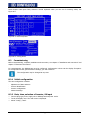
Chart menu ............................................................................................................................52
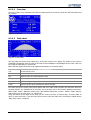
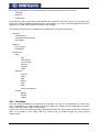
9.2.2.1
Overview .........................................................................................................................53
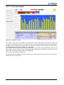
9.2.2.2
Daily chart.......................................................................................................................53
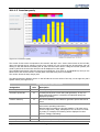
9.2.2.3
Monthly chart ..................................................................................................................56
9.2.2.4
Annual chart....................................................................................................................57
9.2.2.5
Total chart ......................................................................................................................57
9.2.3
Analysis menu ........................................................................................................................58
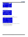
9.2.3.1
Messages ........................................................................................................................58
9.2.3.2
Solar inverter event records.............................................................................................59
9.2.3.3
Alarm contact ..................................................................................................................59
9.2.4
USB menu ..............................................................................................................................59
9.2.4.1
Data export .....................................................................................................................60
9.2.4.2
Data backup ....................................................................................................................60
9.2.4.3
Firmware update .............................................................................................................61
9.2.5
Configuration menu ................................................................................................................61
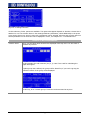
9.2.5.1
Initial configuration (Start) ..............................................................................................61
9.2.5.2
Identification of inverter ..................................................................................................63
9.2.5.3
Inverter configuration......................................................................................................64
9.2.5.4
Network settings (Basic) ..................................................................................................65
9.2.5.5
Internet...........................................................................................................................68
9.2.5.6
Extended .........................................................................................................................70
9.2.5.7
Internal ...........................................................................................................................72
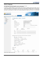
10 Configuration via PC.............................................................................................................. 75
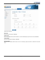
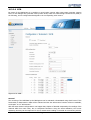
10.1 Yield data ........................................................................................................................ 76
10.1.1 Visualization PC ......................................................................................................................77
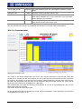
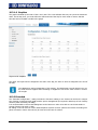
10.1.1.1 Overview daily.................................................................................................................77
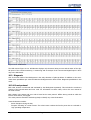
10.1.1.2 Overview monthly ...........................................................................................................79
10.1.1.3 Overview yearly...............................................................................................................81
10.1.1.4 Overview total .................................................................................................................82
10.1.2 Visualization Palm/PocketPC ...................................................................................................83
10.1.2.1 Day view .........................................................................................................................84
10.1.2.2 Month view .....................................................................................................................85
10.1.2.3 Year view ........................................................................................................................86
10.1.3 SCB monitor ...........................................................................................................................86
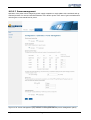
10.2 Diagnosis......................................................................................................................... 87
10.2.1 Event protocol ........................................................................................................................87
10.2.2 Degradation ...........................................................................................................................88
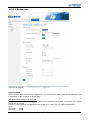
10.3 Configuration .................................................................................................................. 89
10.3.1 Basic Configuration.................................................................................................................89
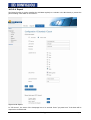
10.3.1.1 LAN – Network settings ...................................................................................................89
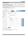
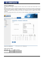
10.3.1.2 Plant groups ....................................................................................................................91
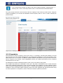
10.3.1.3 Inverter order..................................................................................................................92
10.3.1.4 Inverters .........................................................................................................................93
10.3.1.5 Forecast ..........................................................................................................................96
10.3.1.6 Graphics ..........................................................................................................................98
10.3.2 Extended................................................................................................................................98
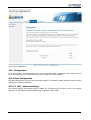
10.3.2.1 Internet...........................................................................................................................99
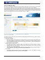
10.3.2.2 Email.............................................................................................................................100
10.3.2.3 SMS ..............................................................................................................................101
10.3.2.4 Export ...........................................................................................................................102
10.3.2.5 Malfunction ...................................................................................................................104
10.3.2.6 iSCB ..............................................................................................................................105
08/10
RPSlog1000
3
10.3.2.7 Power management ......................................................................................................107
10.3.3 Internal ................................................................................................................................108
10.3.3.1 Backup (data backup)....................................................................................................109
10.3.3.2 System data ..................................................................................................................111
10.3.3.3 Update (firmware update) .............................................................................................112
10.4 Homepage ..................................................................................................................... 113
10.5 RPS Portal ..................................................................................................................... 114
10.6 Automatic notification .................................................................................................. 114
10.6.1 Solar inverter failure message - Email...................................................................................114
10.6.2 Solar inverter failure message – SMS....................................................................................114
10.6.3 Power monitoring fault message – Email ..............................................................................114
10.6.4 Power monitoring fault message – SMS ................................................................................114
10.6.5 Status/error code monitoring fault message – Email .............................................................114
10.6.6 Status/error code monitoring fault message – SMS...............................................................115
10.6.7 Alarm contact alarm message – Email ..................................................................................115
10.6.8 Alarm contact alarm message – SMS ....................................................................................115
10.6.9 Yield overview – Email..........................................................................................................115
10.6.10 Yield overview – SMS ...........................................................................................................115
10.7 LED error indication ...................................................................................................... 116
10.8 Reset button ................................................................................................................. 116
10.9 Maintenance and service .............................................................................................. 116
4
RPSlog1000
08/10
List of illustrations
Figure 3-1: RPSlog1000...............................................................................................................................17
Figure 3-2: RPSlog1000 accessories, sensors...............................................................................................18
Figure 5-1: Name plate ...............................................................................................................................23
Figure 6-1: Position for screw fastening.......................................................................................................24
Figure 7-1: Connection options at bottom ...................................................................................................26
Figure 7-2: Connection option at upper side ................................................................................................27
Figure 7-3: Connection options Sensor-Box .................................................................................................28
Figure 7-4: PIN assignment of terminal strip connector RS485-A .................................................................29
Figure 7-5: PIN assignment of terminal strip connector RS485/422-B ..........................................................30
Figure 7-6: PIN assignment of terminal strip connector PM interface ...........................................................30
Figure 7-7: Cabling example including a ripple control receiver....................................................................31
Figure 7-8: RS485 assembly group ..............................................................................................................33
Figure 7-9: RS-485 connection terminal block..............................................................................................33
Figure 7-10: Example for Communication wiring..........................................................................................35
Figure 7-11: 6pin S0-In/Out connector ........................................................................................................37
Figure 7-12: Connector ...............................................................................................................................38
Figure 7-13: Relay contact ..........................................................................................................................38
Figure 7-14: "Alarm contact" connector .......................................................................................................38
Figure 7-15: "S0 output" connector .............................................................................................................40
Figure 8-1: Example 1 Graphic dialogue ......................................................................................................42
Figure 8-2: Graphic dialogue - example .......................................................................................................43
Figure 8-3: Graphic dialogue - example .......................................................................................................43
Figure 8-4: Text dialogues - example ..........................................................................................................43
Figure 8-5: Virtual keyboard ........................................................................................................................44
Figure 8-6: "Config./Start"...........................................................................................................................44
Figure 8-7: "Config./Start"...........................................................................................................................45
Figure 8-8: "Configuration"..........................................................................................................................45
Figure 8-9: "Initial configuration" ................................................................................................................45
Figure 8-10: "Selection of inverter and S0 input" .........................................................................................46
Figure 8-11: Inverter detection ...................................................................................................................47
Figure 8-12: New modem connection ..........................................................................................................49
Figure 8-13: Selection of type of network connection ..................................................................................49
Figure 8-14: Setup connection manually......................................................................................................50
Figure 8-15: Connection via dial-up modem ................................................................................................50
Figure 8-16: Enter name of Internet service provider ..................................................................................50
Figure 8-17: Enter telephone number..........................................................................................................50
Figure 8-18: Enter password ......................................................................................................................51
Figure 8-19: Enter Internet account information..........................................................................................51
08/10
RPSlog1000
5
Figure 9-1: Overview Touchscreen display dialogues ...................................................................................52
Figure 9-2: Overview...................................................................................................................................53
Figure 9-3: Daily chart ................................................................................................................................53
Figure 9-4: Settings submenu .....................................................................................................................54
Figure 9-5: Monthly chart ............................................................................................................................56
Figure 9-6: Annual chart .............................................................................................................................57
Figure 9-7: Total chart ................................................................................................................................57
Figure 9-8: Messages ..................................................................................................................................58
Figure 9-9: Event records ............................................................................................................................59
Figure 9-10: Alarm contact ..........................................................................................................................59
Figure 9-11: Data export .............................................................................................................................60
Figure 9-12: Contents of USB stick ..............................................................................................................60
Figure 9-13: Data backup............................................................................................................................60
Figure 9-14: Firmware update .....................................................................................................................61
Figure 9-15: Initial configuration 1/5 ...........................................................................................................61
Figure 9-16: Initial configuration 2/5 ...........................................................................................................62
Figure 9-17: Initial configuration 3/5 ...........................................................................................................62
Figure 9-18: Initial configuration 4/5 ...........................................................................................................62
Figure 9-19: Initial configuration 5/5 ...........................................................................................................63
Figure 9-20: Inverter identification ..............................................................................................................63
Figure 9-21: Overview of inverter identification ...........................................................................................63
Figure 9-22: Inverter identification message................................................................................................64
Figure 9-23: Selection of solar inverter ........................................................................................................64
Figure 9-24: Module power .........................................................................................................................65
Figure 9-25: Monitoring and graph scaling ..................................................................................................65
Figure 9-26: Network settings .....................................................................................................................66
Figure 9-27: Network settings for router mode ............................................................................................66
Figure 9-28: Network settings for modem mode..........................................................................................67
Figure 9-29: Network settings for GPRS modem ..........................................................................................67
Figure 9-30: Internet initial settings ............................................................................................................68
Figure 9-31: Internet Email/SMS .................................................................................................................69
Figure 9-32: WEB, update interval...............................................................................................................69
Figure 9-33: Text for Internet homepage resp. RPS Portal, online banner, connection test ..........................70
Figure 9-34: "Config. | Extended" menu. .....................................................................................................70
Figure 9-35: System monitoring ..................................................................................................................70
Figure 9-36: Ext. display at RS485-A ...........................................................................................................71
Figure 9-37: Ext. display at RS485-B ...........................................................................................................71
Figure 9-38: Ext. display at S0 output .........................................................................................................71
Figure 9-39: Alarm contact ..........................................................................................................................71
Figure 9-40: Inverter status monitoring 1/5.................................................................................................72
6
RPSlog1000
08/10
Figure 9-41: Inverter status monitoring 2/5.................................................................................................72
Figure 9-42: RS485 Wireless-Set .................................................................................................................72
Figure 9-43: "Config. | Internal" menu. .......................................................................................................72
Figure 9-44: Data correction .......................................................................................................................73
Figure 9-45: Display illumination, slide show ...............................................................................................73
Figure 9-46: Display access protection ........................................................................................................73
Figure 9-47: Serial number..........................................................................................................................73
Figure 9-48: Initialization, resetting, factory settings ...................................................................................73
Figure 9-49: Firmware update .....................................................................................................................74
Figure 9-50: Language settings ...................................................................................................................74
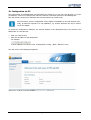
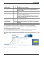
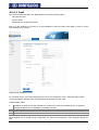
Figure 10-1: Control via a web browser .......................................................................................................75
Figure 10-2: Overview daily.........................................................................................................................77
Figure 10-3: Overview monthly ...................................................................................................................79
Figure 10-4: Overview yearly ......................................................................................................................81
Figure 10-5: Overview total.........................................................................................................................82
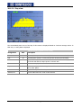
Figure 10-6: Palm/PocketPC visualization ....................................................................................................83
Figure 10-7: Power curve of day .................................................................................................................84
Figure 10-8: Yield diagram - Month view .....................................................................................................85
Figure 10-9: Year view ................................................................................................................................86
Figure 10-10: SCB Monitor ..........................................................................................................................87
Figure 10-11: Event protocol solar inverter..................................................................................................88
Figure 10-12: Degradation ..........................................................................................................................89
Figure 10-13: Configuration of LAN and Internet access ..............................................................................90
Figure 10-14: Managing plant groups ..........................................................................................................91
Figure 10-15: Inverter order........................................................................................................................92
Figure 10-16: Solar inverter data.................................................................................................................93
Figure 10-17: Monitoring .............................................................................................................................94
Figure 10-18: Period without shadowing .....................................................................................................95
Figure 10-19: Snow cover expected ............................................................................................................95
Figure 10-20: Power deviation.....................................................................................................................95
Figure 10-21: Fault period ...........................................................................................................................95
Figure 10-22: Maximum number of messages .............................................................................................96
Figure 10-23: Graph scaling ........................................................................................................................96
Figure 10-24: Forecast ................................................................................................................................97
Figure 10-25: Graphics................................................................................................................................98
Figure 10-26: Internet.................................................................................................................................99
Figure 10-27: Email...................................................................................................................................100
Figure 10-28: SMS ....................................................................................................................................101
Figure 10-29: Export .................................................................................................................................102
Figure 10-30: Malfunction .........................................................................................................................104
08/10
RPSlog1000
7
Figure 10-31: iSCB ....................................................................................................................................105
Figure 10-32: Power management (only available in RPSlog1000 PM with power management option) .....107
Figure 10-33: Backup (data backup) .........................................................................................................109
Figure 10-34: System ................................................................................................................................111
Figure 10-35: Update (firmware update) ...................................................................................................112
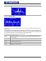
Figure 10-36: Online banner .....................................................................................................................113
8
RPSlog1000
08/10
This document
Dear customer,
This user manual describes the RPSlog1000 by BONFIGLIOLI VECTRON GmbH and its use.
The user manual contains important information on how the RPSlog1000 can be used safely, properly and
efficiently. Compliance with this user manual contributes to avoiding risks, minimizing repair cost and downtimes and increasing the reliability and service live of the RPSlog1000. For this reason, make sure you read
the user manual carefully.
In case any problems occur which are not covered by this user manual sufficiently, please
contact the manufacturer.
Warranty and liability
BONFIGLIOLI VECTRON GmbH would like to point out that the contents of this user manual do not form part
of any previous or existing agreement, assurance or legal relationship. Neither are they intended to supplement or replace such agreements, assurances or legal relationships. The manufacturer's obligations are exclusively specified in the relevant purchase contract. This contract also contains all and any warranty regulations which may apply to the relevant scope of supply. These contractual warranty provisions are neither
extended nor limited by the specifications contained in this documentation.
The manufacturer reserves the right to correct or amend the specifications, product information and omissions in these operating instructions without notice. The manufacturer shall not be liable for any damage,
injuries or costs which may be caused by the aforementioned reasons.
In addition to that, BONFIGLIOLI VECTRON GmbH excludes any warranty/liability claims for any personal
and/or material damage if such damage is due to one or more of the following causes:
-
inappropriate use of RPSlog1000,
-
non-compliance with the instructions, warnings and prohibitions contained in this user manual,
-
unauthorized modifications of the RPSlog1000,
-
insufficient monitoring of parts which are subject to wear,
-
catastrophes by external impact and force majeure.
Obligation
This user manual must be read before commissioning. Anybody entrusted with tasks in connection with the
-
transport,
-
assembly,
-
installation and
-
use of the RPSlog1000
must have read and understood the user manual and, in particular, the safety instructions in order to protect
himself/herself and prevent the RPSlog1000 from being damaged.
Copyright
This user manual is protected by copyright. It is solely intended for use by operating staff and must not be
copied nor disclosed to third parties.
Storage
This user manual is an integral component of the RPSlog1000. It must be stored such that it is accessible to
operating staff at all times. In case the RPSlog1000 is sold to other users, this user manual must also be
handed over.
08/10
RPSlog1000
9
1
General safety instructions and information on use
The chapter 1 "General safety instructions and information on use" contains general safety instructions for
the Operator and the Operating Staff. At the beginning of certain main chapters, some safety instructions
are included which apply to all work described in the relevant chapter. Special work-specific safety instructions are provided before each safety-relevant work step.
1.1
Terminology
Operator
This is the entrepreneur/company who/which operates the RPSlog1000 and uses it as per the specifications
or has it operated by qualified and instructed staff.
Operating Staff
The term Operating Staff covers persons instructed by the Operator of the RPSlog1000 and assigned the
task of operating it.
Qualified staff
The term Qualified Staff covers staff who is assigned special tasks by the Operator of the RPSlog1000 , e.g.
transport, installation, maintenance and service/repair and troubleshooting. Based on their qualification
and/or know-how, qualified staff must be capable of identifying defects and assessing functions.
Qualified electrician
The term Qualified Electrician covers qualified and trained staff who has special technical know-how and
experience with electrical installations. In addition, Qualified Electricians must be familiar with the applicable
standards and regulations and must be able to assess the assigned tasks properly and identify and eliminate
potential hazards.
Instructed person
The term Instructed Person" covers staff who was instructed and trained about/in the assigned tasks and
the potential hazards that might result from inappropriate behavior. In addition, instructed persons must
have been instructed in the required protection provisions, protective measures, the applicable directives,
accident prevention regulations as well as the operating conditions and verified their qualification.
Expert
The term Expert covers qualified and trained staff who has special technical know-how and experience relating to RPSlog1000. Experts must be familiar with the applicable government work safety directives, accident
prevention regulations, guidelines and generally accepted rules of technology in order to assess the operationally safe condition of the RPSlog1000 .
1.2
Designated use
The RPSlog1000 is a data logger for data management and storage and plant monitoring of photovoltaic
plants.
The device may only be used when it is in a technically perfect condition and only for the purpose mentioned
above.
Any other use shall be considered as not in conformity with the designated use.
Applied standards:
-
2006/95 EC Low voltage directive
-
DIN EN 50178 Electronic equipment for use in power installations
-
EN 60204-1 Safety of machinery - Electrical equipment of machines
-
2004/108/EC Electromagnetic compatibility
However, use of the device still holds risk for life and limb of operating staff or other persons as well as the
risk of damaging the RPSlog1000 and/or other tangible assets. Only use the RPSlog1000 if it is in a technically perfect condition and in compliance with its designated use, aware of the risks involved, taking the required safety measures and in compliance with this user manual.
The RPSlog1000 may only be used for data management and storage and plant monitoring of photovoltaic
plants equipped with solar inverter of RPS series. Any other use shall be considered as not in compliance
with the designated use. The manufacturer shall not be held liable for any damage resulting from such noncompliance. The sole risk shall be borne by the operator.
For the performance limits of the RPSlog1000, refer to chapter 4 "Technical data".
10
RPSlog1000
08/10
1.3
Misuse
Any use other than that described in "Designated use" shall not be permissible and shall be considered as
misuse.
The following is not permitted:
-
use by uninstructed staff,
-
use of the device while it is not in perfect condition.
The manufacturer shall not be held liable for any damage resulting from such misuse. The sole risk shall be
borne by the operator.
1.3.1 Explosion protection
The RPSlog1000 is an IP 20 protection class device. For this reason, use of the device in explosive atmospheres is not permitted.
1.4
Warning information and symbols used in the user manual
1.4.1 Hazard classes
The following hazard identifications and symbols are used to mark particularly important information:
DANGER
Identification of immediate threat holding a high risk of death or serious injury if not avoided.
WARNING
Identification of immediate threat holding a medium risk of death or serious injury if not
avoided.
CAUTION
Identification of immediate threat holding a low risk of minor or moderate physical injury if
not avoided.
NOTE
Identification of a threat holding a risk of material damage if not avoided.
08/10
RPSlog1000
11
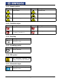
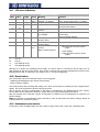
1.4.2 Hazard symbols
Symbol
Meaning
Symbol
Meaning
General hazard
Suspended load
Electrical voltage
Hand injury
Danger of crushing
Hot surfaces
1.4.3 Prohibition signs
Symbol
Meaning
Symbol
Meaning
No persons with pacemakers
Fire, open flames forbidden
No switching; it is forbidden to switch
the machine, assembly on
No smoking
1.4.4 Recycling
Symbol
Meaning
Recycling; to avoid waste, collect all
materials for reuse.
1.4.5 Grounding symbol
Symbol
Meaning
Ground connection
1.4.6 ESD symbol
Symbol
Meaning
ESD: Electrostatic Discharge (can
damage components and assemblies)
1.4.7 Information signs
Symbol
Meaning
Tips and information making using the
RPSlog1000 easier.
12
RPSlog1000
08/10
1.5
Marking of text passages
Special passages in the user manual are marked by the following symbols:
-
Marking of lists.
•
Marking of instructions and information in safety instructions.
1.6
Conformity
The declaration of conformity will be supplied by the manufacturer upon request.
1.7
Directives and guidelines to be adhered to by the operator
The operator must follow the following directives and regulations:
•
Ensure that the applicable workplace-related accident prevention regulations as well as other applicable
national regulation are accessible to the staff.
•
An authorized person must ensure, before using the PPSlog1000, that the device is used in compliance
with its designated use and that all safety requirements are met.
•
Additionally, comply with the applicable laws, regulations and directives of the country in which the
RPSlog1000 is used.
1.8
•
Operator's general plant documentation
In addition to the user manual, the operator should issue separate internal operating instructions for the
RPSlog1000. The user manual of the RPSlog1000 must be included in the user manual of the whole
plant.
1.9
Operator's/operating staff's responsibilities
1.9.1 Selection and qualification of staff
•
Any work on the RPSlog1000 may only be carried out by reliable staff. The staff must not be under the
influence of any drugs. Note the minimum age required by law. Only employ qualified or instructed staff.
Define the staff's responsibility in connection with all work with RPSlog1000 clearly.
•
Work on the electrical components may only be performed by a qualified electrician according to the
applicable rules of electrical engineering.
1.9.2 General work safety
•
In addition to the user manual, any applicable legal or other regulations relating to accident prevention
and environmental protection must be complied with. The staff must be instructed accordingly. Such
regulations and/or requirements may include, for example, handling of hazardous media and materials
or provision/use of personal protective equipment.
•
In addition to this user manual, issue any additional directives that may be required to meet specific
operating requirements, including supervision and reporting requirements, e.g. directives relating to
work organization, workflow and employed staff.
•
Do not change or modify the RPSlog1000 in any way that might affect safety, unless such change or
modification has been approved expressly by the manufacturer.
•
Only use the RPSlog1000 if the rated connection and setup values specified by the manufacturer are
met. Only use original spare parts.
•
Provide appropriate tools as may be required for performing all work on the RPSlog1000 properly.
08/10
RPSlog1000
13
1.10 Organizational measures
1.10.1 General
•
Train your staff in the handling and use of the RPSlog1000 as well as the risks involved.
•
Use of any individual parts or components of the RPSlog1000 in other parts of the operator's plant is
prohibited.
1.11 Handling and installation
•
Do not commission any damaged or destroyed components.
•
Prevent any mechanical overloading of the RPSlog1000.
•
Do not touch any electronic construction elements and contacts. The RPSlog1000 is equipped with
components which are sensitive to electrostatic energy and can be damaged if handled improperly. Any
use of damaged or destroyed components shall be considered as a non-compliance with the applicable
standards.
•
The RPSlog1000 may only be installed in suitable operating rooms.
1.12 Electrical connection
•
The five safety rules must be complied with.
•
Never touch terminals which are energized in operation because the capacitors may still be charged
even if the device is switched off.
•
Before carrying out any assembly and/or connection work, switch off the RPSlog1000.
•
When performing any work on/with the RPSlog1000, always comply with the applicable national and
international regulations/laws on work on electrical equipment/plants.
•
Connect the RPSlog1000 in accordance with the technical data and only with a power supply appropriate
for this type of application.
1.12.1 Safety regulations
For work with electrical equipment. When working on/in electrical plants, always follow the five safety rules.
1 Disconnect mains,
2 Prevent reconnection,
3 Test for absence of harmful voltages,
4 Ground and short circuit,
5 Cover or close off nearby live parts.
1.13 Safe operation
•
During operation of the RPSlog1000, always comply with the applicable national and international regulations/laws on work on electrical equipment/plants.
•
Never perform any connection works during operation of the RPSlog1000.
•
In order to avoid accidents or damage, only qualified staff and electricians may carry out the work such
as installation, commissioning or setup.
•
In the case of a defect of terminals and/or cables, immediately disconnect the RPSlog1000 from mains
supply.
•
Persons not familiar with the operation of RPSlog1000 as well as children must not have access to the
RPSlog1000. Do not bypass nor decommission any protective facilities.
•
Only use original accessory .
14
RPSlog1000
08/10
1.14 Maintenance and service/troubleshooting
•
Work on the electrical components must not be done.
•
Unauthorized opening and improper interventions can lead to material damage. Repairs on the
RPSlog1000 may only be carried out by the manufacturer or persons authorized by the manufacturer.
1.15 Utilities and operating materials
Comply with all applicable environmental protection regulations. Ensure that all utilities and operating materials are disposed of properly.
08/10
RPSlog1000
15
2
Transport and storage
Only store the RPSlog1000 in its original package in dry rooms which are protected against dust and moisture and are subjected to little temperature deviations only. Transport and storage temperature: -20 …
70 °C, relative air humidity: 5 … 95 %, not condensing.
16
RPSlog1000
08/10
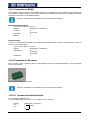
3
Scope of supply
The RPSlog1000 is delivered including the following components:
-
RPSlog1000
-
Plug-type power supply unit 12 V
-
User manual
-
Terminal strip connector for all connections (except for CAN): 2 x 3 pins, 1 x 4 pins, 2 x 6 pins.
-
4 anchors and screw material for wall mounting
With PM (power management) option, additionally:
-
Ripple control receiver connecting cable
Figure 3-1: RPSlog1000
Additionally required:
-
Network cable (RJ45-CAT5 or CAT6) for connection to PC or network
-
Cable material for cabling of inverters with one another
08/10
RPSlog1000
17
3.1
Options
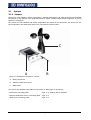
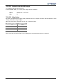
3.1.1 Sensors
Sensors for solar radiation, module temperature, ambient temperature and wind speed provide important
information for the analysis of the yield data and thus enable a reliable target/actual comparison as well as
rapid error recognition.
The sensors for solar radiation and module temperature are housed in the Sensor-Box, the sensors for ambient temperature and wind speed have to be connected to the Sensor-Box.
C
A
B
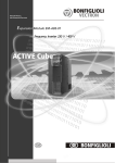
Figure 3-2: RPSlog1000 accessories, sensors
A
RPSlog Sensor-Box
B
Ambient temperature sensor
C
Wind sensor
The sensors are equipped with cables for connection to data logger or Sensor-Box.
- Sensor-Box connecting cable
4-pin, 3 m, weather and UV-resistant
- Ambient temperature sensor connecting cable
3-pin, 3 m
- Wind sensor connecting cable
2-pin, 5 m
18
RPSlog1000
08/10
3.1.2 RPSlog1000 Modem Package
The analogue modem is available in two variants:
-
Analogue Modem Home
-
Analogue Modem Industrial
An analogue telephone connection is required for operation of the modem. Such a connection is normally
available in the case of an ISDN telephone system.
Scope of supply RPSlog1000 Modem Package
-
Analogue Modem
-
serial RS232 cable
-
Telephone connection cable
-
Power supply unit
3.1.3 RPSlog1000 Mobile Package
The Mobile Package connects the RPSlog1000 to the Internet via the mobile phone network. In addition to
the Mobile Package, you will need a SIM card of your mobile network operator (not included in scope of
supply).
Scope of supply of RPSlog1000 Mobile Package
-
mobile phone modem GPRS
-
serial RS232 cable
-
power supply unit
-
external antenna with 2 m connecting cable
08/10
RPSlog1000
19
4
Technical data
Supply voltage
Technical data data logger RPSog1000
12 V DC
Energy consumption
approx. 3.5 Watt
Power supply
external plug-type power supply unit
Dimensions (W x H x D)
220 x 210 x 50 mm
Housing
Plastic housing, passive ventilation
Interfaces, inputs and outputs
Ethernet with RJ45 socket, 10/100 MBit,
2 x RS485, including 1 RS422,
Relay, 24 V DC, max. 5 A,
S0 pulse input/output (according to DIN 43864 and EN
62056),
Alarm contact, max. cable length 1000 m,
USB host,
RS232 modem interface,
Reset button
Memory capacity
8 MByte RAM and 1024 MB FlashRAM
Degree of protection
IP 20 (for indoor use only)
Temperature range
-10 … 50 °C
Display
4 LEDs for status indication
Installation
Wall mounting
Weight
0.61 kg
20
RPSlog1000
08/10
Technical data Sensor-Box
Power supply
Via RS485 data cable of RPSlog (12-28VDC); no additional
power supply required.
Dimensions (W x H x D)
145 x 85 x 40 mm
Weight
approx. 360 g
Housing
Powder-coated aluminum
Degree of protection
IP 65
Solar cell
Monocrystalline silicon (50 mm x 33 mm)
Current measurement shunt
1 Ω (TK 30 ppm/K)
Insolation sensor
± 5 % (0 W/m² to 1400 W/m²); error with temperature
compensation compared to pyranometer across the
working range of -20 °C to 70 °C (vertical light impact).
Cell temperature
± 1K (-20 °C to +70 °C)
Outdoor temperature
± 1K (-20 °C to +70 °C)
Temperature range
-20 °C … +75 °C
Operating temperature
-20 °C … +70 °C
Deviation at 25 °C
± 1.5 °C
Non-linearity
± 1.5 °C
Deviation at minimum and maximum tempera± 2.0 °C
ture
Power consumption
40 mA typical at 20 V DC
Interface
RS485
Galvanic isolation
1000 V between supply and RS485 bus
Installation
On modular mounting rails; matching screws included in
scope of supply. All sensors are screwed. Opening the sensors is not permitted.
Sensor-Box connecting cable
4-pin, 3 m, weather and UV-resistant
Ambient temperature sensor connecting cable
3-pin, 3 m
Measuring range of ambient temperature sen-20 °C to +70 °C
sor in stainless steel sleeve
Wind sensor connecting cable
2-pin, 5 m
Wind sensor
± 5 % (0.8 m/s to 40 m/s, max. 60 m/s for a short time, 25 °C to +60 °C, free from ice)
Conformity
CE according to DIN EN-61000-6-1:2007 and
DIN EN-61000-6-3:2007
08/10
RPSlog1000
21
5
Product overview / Description of function
5.1
Description of function
The RPSlog1000 data logger enables monitoring of solar inverters, including data storage and data transmission. Monitoring is possible both on site and via remote maintenance. On site, the data is provided via the
serial RS232 interface. For remote maintenance, data transmission can be made through the RJ45-LAN interface (DSL) or the RS232 interface (GPRS, analog modem) via an Internet connection.
The RPSlog1000 can be controlled via the touch screen display or a web browser.
Up to 20 solar inverters can be connected per RPSlog1000.
The data is saved on the device and can be uploaded on a website or Web-Portal, where it can be processed
and viewed in various graphical representations.
The data can be also exported as an CSV file.
The following data can be captured and transmitted:
-
Yield data of a day, month, year (AC power, DC power, energy, spec. yield, etc.)
-
Efficiency
-
DC voltage
-
Inverter temperature
If optional sensors are used, additional data can be captured:
-
Solar radiation
-
Module temperature
-
Ambient temperature
-
Wind speed
For analysis, set points or expected yields can be defined and compared to the actual values in a graphical
representation.
With PM (power management) option:
As from January 2009, it must be possible for grid operators to reduce the supplied effective power of photovoltaic plants in Germany with a generator power 100 kWp and more (Article 6.1 EEG). The RPSlog1000,
in the PM variant, features an additional supply power management for plants with a generator power of
100 kWp and more.
The interface are four digital inputs for the connection of a ripple control receiver.
Features of RPSlog1000:
-
Graphical touch screen display
-
Relay for external alarming
-
LAN interface (10/100 MBit/s)
-
Web control
-
Email/SMS/Homepage messaging
-
Remote inquiry
-
S0 input for digital energy meters
-
USB port for data transfer via USB stick
-
1 GByte memory for yield data
-
Monitoring/recording for up to 20 inverters. Monitoring is possible both on site and via remote maintenance.
Additionally with PM variant:
4 digital inputs for controlling of feed-in power.
22
RPSlog1000
08/10
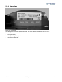
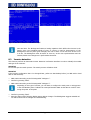
5.1.1 Name plate
Figure 5-1: Name plate
The RPSlog1000 is identified by the name plate. The name plate is located below the top cover.
It contains
-
the type number,
-
the input voltage [VDC] and
-
the serial number (SN).
08/10
RPSlog1000
23
6
Installation and connection
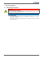
6.1
Mechanical installation RPSlog1000
The RPSlog1000 has to be mounted close to the solar inverters that are be monitored. A minimum distance
of 2 meters between the data logger and the nearest solar inverter has to be kept.
To fix the RPSlog1000, proceed as follows:
•
Take off the two gray covers.
•
Fix the RPSlog1000 using the supplied screws and the holes provided in the device.
•
Fix the covers again applying gentle pressure.
Figure 6-1: Position for screw fastening
6.2
Mechanical installation Sensor-Box
Ensure that the pressure equalization element (next to cable gland) is not damaged. If the
cover of the pressure equalization element is loosened during assembly, it can be fixed again,
provided that the pressure equalization element or the cover is undamaged.
The Sensor-Box must be fixed parallel, i.e. with identical alignment and inclination, with the modules on a
mounting rail using the supplied fixing screws. The installation location should be selected so that no shadowing can occur.
Fix the Sensor-Box via the two wall brackets to a suitable substructure using at least one M6 screw and a
washer per bracket.
The module temperature is captured via an integrated cell temperature sensor so that no additional assembly on module back panel is required.
The ambient temperature sensor is screwed to the Sensor-Box (3-pin connection). Tighten screw firmly.
Mount the sensor at a shady location using the wall fixture. The cable must not be extended.
The wind sensor is screwed to the Sensor-Box (2-pin connection). Tighten screw firmly. Fix the wind wheel
at a high, exposed location if possible. The cable must not be extended.
24
RPSlog1000
08/10
7
Electrical connections
7.1
Special safety instructions
DANGER
Electric shock by live components!
In the case of improper installation, accidents or material damage may result from noncompliance with the safety instructions. Note:
NOTE
Damage RPSlog1000
•
Only use the supplied power supply unit. The RPSlog1000 is operated at 12 - 24 volt direct current (12 - 24 VDC).
•
08/10
The RPSlog1000 has degree of protection IP20. The relay may be loaded at a maximum
of 24 Volt DC and 5A.
RPSlog1000
25
7.2
Connection options RPSlog1000
Bottom side:
Figure 7-1: Connection options at bottom
Connection options at bottom side
1
Rel.
Relay for switching external signals, e.g. warning beacons, etc.
2
RS485-A
First RS485 interface. Connection to inverter and/or large display
3
RS485/422-B
Second RS485 interface. Connection to Sensor-Box
4
Power
12 - 24 Volt direct voltage input
5
Network
Ethernet network interface, 10/100 MBit
6
RS232
RS232 modem interface. Connection to analog or GPRS modem
26
RPSlog1000
08/10
Upper side:
F
A
B
Figure 7-2: Connection option at upper side
C D
E
Connection options at upper side
A
Reset
Reset button. Restart RPSlog1000; no resetting of data.
B
USB
USB host connection. Suitable for USB sticks with a capacity to 2 GByte. Not suitable for connection to PC.
C
CAN
CAN-Bus intended for future extensions. Currently not used. No terminal strip connector is provided for this socket.
D
Alarm
Alarm contact, e.g. for connection of an anti-theft contact loop.
With bell wire up to 1000 m.
E
S0-In/Out
S0 pulse input for connection to external energy meter.
S0 pulse output for connection to external large display.
F
PM (optional)
Power Management. Port for connection of ripple control receivers for effective
power reduction management.
08/10
RPSlog1000
27
7.3
Electrical connections of Sensor-Box
C
D
A B
Figure 7-3: Connection options Sensor-Box
A
C
Ambient temperature sensor connection port
Pressure equalization element
B
D
Wind sensor connection port
RPSlog1000 connection port
Color assignment of connecting cable from Sensor-Box to RPSlog1000:
Connecting cable to RPSlog1000
Color of wire
Assignment
red
power supply (plus 12V)
black
power supply (ground)
brown
A (Data +)
orange
B (Data -)
black (large crossshield
section)
The connecting cable has 4 wires and includes 12 V power supply and the data line to the RPSlog1000. No
separate power supply unit is required for the Sensor-Box. The connecting cable may be extended (max.
200 m), an appropriate cable cross-section has to be used. In outdoor environments, the cable connection
must be protected appropriately, with the minimum protection class IP54.
NOTE
Damage RPSlog1000
•
Penetrating moisture can result in short circuits and destroy the Sensor-Box and
RPSlog1000.
•
The shield must be connected with a potential equalization system.
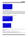
The Sensor-Box has to be connected to the RS485/422-B socket of the RPSlog1000. That followed the Sensor-Box has to be integrated in the system by the inverter detection, here the corresponding socket has to
be configured in the RPSlog1000 for interface type "M&T Sensor".
The overvoltage protection concept must be adapted to the local conditions.
28
RPSlog1000
08/10
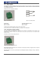
7.3.1 Terminal strip connector and cable
Green terminal strip connectors are supplied for connection of the RPSlog1000 to the inverter. The PIN assignment at the device is shown in Figure 7-4 and Figure 7-5.
7.3.1.1
Cable sets
•
For values, refer to table "Connection".
•
Connect terminal strip on both sides.
Connection
Maximum cable length
2400 … 4800 Baud: 2400
9600 … 19200 Baud: 1200
57600 Baud:
600
115200 Baud:
300
RPSlog1000 <-> inverter
RPSlog1000 <-> Sensor Box
200
Type of cable
m
2-wire, pairwise twisted cable with
m
braided shield (no foil shield), wire size
m
at least 0.5 mm²
m
4-wire, pairwise twisted cable with
braided shield (no foil shield), UVresistant
cross-section at least 0,22 mm2
The maximum cable length depends on the baud rate. For information regarding the baud rate, refer to the
instructions of the solar inverter.
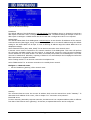
7.3.1.2
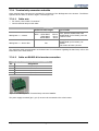
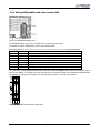
Cable set RS485-A for inverter connection
4-pin green terminal strip connector RS485-A
Pin
Assignment
1
A (Data+)
2
3
4
12 V
Ground
B (Data-)
Figure 7-4: PIN assignment of terminal strip connector RS485-A
The power supply terminals (pin 2, pin 3) must not be connected to the solar inverter.
08/10
RPSlog1000
29
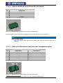
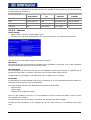
7.3.1.3
Cable set RS485/422-B for Sensor-Box connection
6-pin green terminal strip connector RS485/422-B
Pin
Assignment
1
A (Data+)
2
12 V
3
4
Ground
B (Data-)
Figure 7-5: PIN assignment of terminal strip connector RS485/422-B
4-pin connected connectors can also be plugged in the left-hand side of the 6-pin connector.
NOTE
Damage RPSlog1000
•
Plug in on left-hand side. Otherwise the RPSlog1000 and the interface boards may be
damaged.
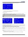
7.3.1.4
Pin
1
2
3
4
5
6
Cable set for PM interface (only for power management option)
6-pin green terminal strip connector PM interface
Assignment
Description1
+5 V
D_IN_1
Level 1
D_IN_2
Level 2
D_IN_3
D_IN_4
+5 V
Level 3
Level 4
Figure 7-6: PIN assignment of terminal strip connector PM interface
1
The level are freely configurable by means of the user interface of RPSlog1000.
30
RPSlog1000
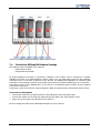
08/10
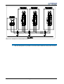
Figure 7-7: Cabling example including a ripple control receiver
7.4
Connection RPSlog1000 Modem Package
The analog modem is available in two variants:
-
Analog Modem Home
-
Analog Modem Industrial
An analog telephone connection is required for operation of the modem. Such a connection is normally
available in the case of an ISDN telephone system. Check if you can make phone calls from the telephone
connection used. For the data connection to the Internet, the RPSlog1000 establishes an Internet-by-Call
connection. Some telephone systems are provided with functions preventing establishing such a connection.
If the dial-in function of the RPSlog1000 is to be used, the corresponding phone number must be assigned
to the phone outlet used.
If necessary, check the connection using a telephone: Make an external phone call and have others call you.
Connection to RPSlog1000
•
Connect the modem to the RS232 terminal of the RPSlog1000 using the RS232 cable.
•
Connect the modem to the telephone cable and plug the cable in the TAE telephone outlet.
•
Plug in the power supply unit and switch the modem on.
All other settings are made via the RPSlog1000 display. No PC is required.
08/10
RPSlog1000
31
7.5
Connection RPSlog1000 Mobile Package
The Mobile Package connects the RPSlog1000 to the Internet via the mobile phone network. In addition to
the Mobile Package, you will need a SIM card of your mobile network operator (not included in scope of
supply).
Connection to RPSlog1000
•
Insert the SIM card in the modem. Using a pointed object, press the yellow eject button on the side of
the modem.
•
Fix the external screw antenna to the modem. Find a suitable place with good reception quality for the
magnetic base antenna. If necessary, check the reception quality using a mobile phone. Good reception
is essential for a reliable data connection.
•
Connect the modem to the RPSlog1000 using the RS232 cable.
•
Plug the RJ11 connector of the power supply unit in the modem.
All other settings are made via the RPSlog1000 display. No PC required.
7.6
Connection to solar inverter RPS
DANGER
Electric shock by live components!
In the case of improper installation, accidents or material damage may result from noncompliance with the safety instructions. Note:
•
Disconnect inverter from power supply.
Attention!
The solar inverters are designed according to the requirements and limit values of product norm EN 61800-3
with an interference resistance (EMI) for operation in industrial installations.
Electromagnetic interference is to be avoided by expert installation and consideration of the specific product
information.
•
A twisted and shielded cable is to be used for the RS485 bus line.
•
The shield must be a braided shield (no foil shield).
•
The shield is to be connected to PE properly on both sides (large contact surface).
•
The so-called semi-duplex/2-wire method is the transmission method used.
For more information of the communication of the solar inverter RPS refer to the corresponding manual.
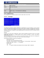
32
RPSlog1000
08/10
7.6.1 Wiring RPSlog1000 with solar inverter RPS
Figure 7-8: RS485 assembly group
The RS485 assembly group can be found on the frequency inverter AEC.
For details on the pin assignment, refer to the following table.
Bus connector X310 CM-485T (7-pin terminal strip)
Terminal
1
2
3
4
5
6
7
Name
A (Data +)
A’ (Data +)
B (Data -)
B’ (Data -)
+5 V
0V
PE
Function
Short-circuit proof and functionally insulated; max. current 60 mA
Bridge from pin 1 for cable loops
Short-circuit proof and functionally insulated; max. current 60 mA
Bridge from pin 3 for cable loops
Supply voltage +5 V
Earth / GND
Shield
The connection of the RS485-Interface has to be done via terminal X4.2 which can be found in the bottom
area of the cabinet. The shield has to be connected via the shield terminal to the designated shield busbar.
More details of wiring can be found in the circuit diagram which is enclosed to the cabinet.
Figure 7-9: RS-485 connection terminal block
08/10
RPSlog1000
33
Details of the assignment of terminal block X4.2 are listed in the following table.
Terminal block X4.2
Terminal
1
2
3
4
Name
A
A’
B
B’
Function
Short-circuit proof and functionally insulated; max. current 60 mA
Bridge from pin 1 for cable loops
Short-circuit proof and functionally insulated; max. current 60 mA
Bridge from pin 3 for cable loops
7.6.2 Bus termination
The physically first and last client must be terminated and so provided with a bus termination resistor. For
this purpose the DIP switch S1 has to be used in the solar inverter, see Figure 7-8: RS485 assembly group”.
This is a passive termination. The data logger RPSlog1000 represents the first client on the bus and is terminated by default.
By default, the bus termination of the solar inverter is OFF
NOTE
34
•
Ensure proper bus termination. Otherwise, communication via the RS485 interface is not
possible.
•
Active termination is permissible only once per network. Termination via an external circuit and the DIP switch at the same time is not permissible.
•
Ensure that the GND is not interrupted. In practice, this result in a better fault behaviour.
•
The terminals for signals A and B are parallel. This enables wiring of several inverters.
RPSlog1000
08/10
Figure 7-10: Example for Communication wiring
Note
•
08/10
With the RPSlog1000 it is possible to record the data of maximum twenty solar inverters.
RPSlog1000
35
7.6.2.1
Setting the solar inverter RPS address
The node address of a solar inverter is set via parameter RS232/RS485 NodeID 394. Up to 20 solar inverters can be connected via the RS485 bus to the RPSlog1000. The solar inverters are assigned unambiguous
addresses in the range from 1 to 30.
Parameter
No.
Setting
Description
394
Min.
Max.
Default
1
30
1
RS232/RS485 NodeID
For operation of the RS485 assembly group, each client must be assigned an address
Bus addresses may only be assigned once, i.e. no double assignments.
An address change is effective immediately, i.e. without a restart of the frequency inverter.
7.7
Connection of Sensor Box
Via the Sensor-Box, the RPSlog1000 can capture and store environmental data. Environmental data include:
-
Solar radiation
-
Module temperature
-
Ambient temperature
-
Wind speed
This data is important for further yield control evaluations and analyses.
Only one Sensor Box can be connected to the RPSlog1000.
The Sensor Box is connected via the RS485B interfaces of the RPSlog1000 which have to be configured for
the interface type via the display.
The Sensor Box is powered with 12 V by the RPSlog1000.
This means, that 4-wire cabling to the Sensor Box is required.
Terminal assignment is as follows:
Cabling of Sensor-Box
Connection
RS485RPSlog1000
Sensor-Box
1
A (Data +)
Brown
2
+12 V
Red
3
GND
Black
4
B (Data -)
Orange
The max. cable length between the RPSlog1000 and the Sensor Box is approx. 200 m.
7.7.1 Commissioning of Sensor Box
As soon as the RPSlog1000 is turned on, the Sensor Box will also be powered automatically. It will take approx. 1 minute for the Sensor Box to be initialized.
The Sensor Box is integrated in the system like an inverter via the display dialogue "Inverter identification".
36
RPSlog1000
08/10
7.8
Connection of external electricity meters
External electricity meters can be connected to the RPSlog1000 via the S0 input. An external three-phase
electricity meter of the whole plant can give an exact reference measurement for example when a solar
plant is owned by more than one party, giving accurate interval billing possibilities.
The electricity meter is listed as a virtual inverter on the RPSlog1000. The pulses are placed in a momentary
power value (Pac) and the total income is offset.
Therefore, the RPSlog1000 is capable of monitoring a plant without further connections to inverters. Especially then, when the installed inverter data protocol is not supported yet. Together with the radiation sensor
from the Sensor Box, the RPSlog1000 can be used as a monitoring device for such installations.
The S0 terminal of the external power meter is connected to the 6-pin S0-In/Out connector as follows:
Figure 7-11: 6pin S0-In/Out connector
RPSlog1000
1
2
3
bridged
4
5
not assigned
6
not assigned
S0
S0+
S0-
The length of the cable between the power meter and the RPSlog1000 should not exceed 10m.
By default, the pulse factor is set to 1000 pulses/kWh and can be set on the RPSlog1000 display in dialogue
"Config. | Basic | Inverter" at inverter 1. The external power meter is seen as an solar inverter and is assigned the first address.
08/10
RPSlog1000
37
7.9
Alarm contact
The RPSlog1000 features a floating control relay which switches in case of an alarm or failure. Its maximum
load capacity is 24 Volt and 5 Ampere, which means that a 220 V consumer cannot be controlled directly but
via an additional load relay.
Cabling is done via a 3-pin plug connector:
3
2
1
Figure 7-13: Relay contact
Figure 7-12: Connector
In OFF state:
PIN 1-2 is open
PIN 2-3 is closed
In ON stat (alarm/fault active):
PIN 1-2 is closed
PIN 2-3 is open
Typically, PIN1 and PIN2 should be used to control the load relay.
For the setting options on RPSlog1000 display, see chapter “9.2.5.6 Extended”.
7.10 Connection of alarm contact
The alarm contact of the RPSlog1000 is triggered if the connection is interrupted. For the wiring on the
mounting-rail, a weather-resistant, thin cable should be used, that rips under strain. The maximum cable
length is 1000 m.
Connection is done via a 3-pin plug connector:
Figure 7-14: "Alarm contact" connector
PIN1 and PIN3 must be connected. If the connection is interrupted, the alarm is triggered which is reported
via the relay, email or SMS.
The alarm function can be set up and tested on the RPSlog1000 display in dialogue "Config | Extended |
Alarm contact".
38
RPSlog1000
08/10
7.11 Connection to PC/network
The RPSlog1000 features a Standard Ethernet RJ45 network port which can be connected using standard
network cables. The speeds 10 Mbit and 100 Mbit are supported.
Generally any PC network technology can be used for connecting the RPSlog1000. The following technology
is available:
-
Direct cable connection
-
Connection via network router
-
Connection through mains power (PowerLine)
-
Connection via wireless (WLAN/GSM)
Connect the RPSlog1000 via an Ethernet RJ45 network cable to your PC or, if applicable, your network
router.
In the case of a direct RPSlog1000 PC connection, a crossover network cable must be used.
If the PowerLine package is used, the RPSlog1000 can be connected via the supplied network cable with the
PowerLine plug. The PC/switch or Internet router has to be connected via the second PowerLine plug. The
two PowerLine plugs connect automatically and then serve as "network cable via the mains power line". The
PowerLine plugs should not be connected via multiple power socket, as power supplies would disrupt the
data quality.
The IP address of the RPSlog1000 can be configured via the display. This process is described in the chapter
8.2 "Commissioning".
7.12 Internet ports
If the RPSlog1000 is connected to the Internet via a router, it must be ensured that the following ports are
enabled on the router:
Port
Port
Port
Port
Port
21 TCP
25 TCP
53 UDP/TCP
80 TCP
123 UDP
FTP data transfer (passive mode)
SMTP email sending
DNS name resolution (separate DNS possible)
HTTP web server
NTP time server
7.13 Connection of large display
Generally, there are two ways to connect large displays to the RPSlog1000:
-
via RS485
-
via S0 pulse output
If possible use the RS485 connection variant. Via the S0 output, only the current feed-in power can be
transmitted as a sequence of pulses, the display must calculate the power and total yield itself.
If the RS485 bus is already occupied by an inverter, a display can still be looped parallel into the data bus.
Observe strictly the instructions from the display manufacturer regarding the wiring and possible preconfiguration.
08/10
RPSlog1000
39
7.13.1 Connection to RS485
If the RS485 variant is chosen, both RS485 interfaces of the RPSlog1000 are available. A large display can
be connected to both interfaces, even if solar inverters are already connected there. Preferably, the display
should be connected to a free RS485 interface.
Note the manufacturer's specifications when connecting the display.
Schneider Displaytechnik:
3-pin. control cable 3 x 0.5 mm²
Display
RPSlog1000 – RS485-A/B
brown-A
1
2 (unused)
gray-GND
3
blue-B
4
RiCo-Electronic:
In order to connect the RiCo display to the RPSlog1000 via RS485, PINs 1 and 2 on terminal block 3 must be
connected in the RiCo device.
2-pin. control cable 2 x 0.5 mm²
Display
RPSlog1000 – RS485-A/B
PIN1:Data+
1
2 (unused)
3 (unused)
PIN2:Data4
7.13.2 Connection to S0 output
The S0 output can be operated in various configurations which are activated depending on the assignment
of the 6-pin terminal.
Figure 7-15: "S0 output" connector
Note the manufacturer's specifications when connecting the display.
7.13.2.1 Current controlled S0 output
(e.g. Schneider Displaytechnik)
A 2-pin shielded cable, 2 x 0.6 mm², max. length 100 m is required.
Display
S0+
S0-
40
RPSlog1000 – S0-In/Out
4
bridged
5
6
RPSlog1000
08/10
7.13.2.2 Contact controlled S0 output
(e.g. displays made by RiCo-Electronic)
A 2-pin shielded cable, 2 x 0.6 mm², max. length 100 m is required.
Display
S0S0+
RPSlog1000 – S0-In/Out
6
5
7.13.2.3 Pulse factor
By default, the RPSlog1000 outputs 1000 pulses/kWh on the S0 output. This value can be adjusted in menu
"Config. | Extended | Large display".
Adjust the pulse factor, depending on the size of the plant (kWp).
Size of plant kWp
30
60
100
150
300
600
Pulse factor
2000
1000
600
400
200
100
Please note that the impulse factor on the RPSLog1000 and the display needs to be identical.
08/10
RPSlog1000
41
8
Operation
8.1
Control elements
The RPSlog1000 is controlled via the integrated touch screen display. Generally, there are two different control interfaces:
-
Graphic dialogues
-
Text dialogues
8.1.1 Touch screen display
NOTE
•
Do not use hart, pointed objects for controlling the display. Other wise the screen might
be damaged.
•
If the RPSlog1000 does not respond immediately, wait for a few seconds and try again.
Don't press harder!
To select a function, slightly touch the relevant button with your finger.
The whole display surface is touch-sensitive, i.e. the control elements may be located
anywhere on the screen.
8.1.2 Graphic dialogues
8.1.2.1
Using graphic dialogues
The graphic dialogues feature action areas and action buttons.
Figure 8-1: Example 1 Graphic dialogue
-
42
If touched, action buttons will perform the relevant function.
RPSlog1000
08/10
-
If touched, action areas will open another graphic or text dialogue. In the example shown in Figure 8-3,
touching the action area will open the graphic dialogue "Main menu".
Action areas are not labeled and are not always identifiable as control elements, see Figure 8-2 (thee month
view is opened) and Figure 8-3 (the main menu is opened).
Figure 8-2: Graphic dialogue - example
Figure 8-3: Graphic dialogue - example
8.1.3 Text dialogues
The text dialogues feature action buttons.
Figure 8-4: Text dialogues - example
If pressed, action buttons bearing a certain designation perform the indicated functions.
If you touch the screen outside of the buttons, the screen returns to the previous dialogue; changes will not
be saved.
The "Menu" action button is always located at the bottom left.
08/10
RPSlog1000
43
Action buttons with input fields, activate a virtual keyboard which you can use for entering values, see
Figure 8-5".
Figure 8-5: Virtual keyboard
Figure 8-6: "Config./Start"
8.2
Commissioning
Before commissioning, complete installation and connection, see chapter 6 "Installation and connection" and
chapter 7 “Electrical connections”.
For commissioning, the RPSlog1000 must be configured. Configuration is done via the display. Exception:
For configuration of the general Internet settings, you will need a PC.
The configuration may be changed at any time.
8.2.1 Initial configuration
The start configuration includes:
-
Adjustment of date and time
-
Inverter identification
-
Inverter configuration
-
Network settings
8.2.2 Date, time, selection of inverter, S0 input
•
Connect plug-type power supply unit to RPSlog1000 and power outlet.
•
Touch the display once. The main menu is displayed.
•
Select "Config. | Start".
44
RPSlog1000
08/10
Figure 8-7: "Config./Start"
•
Select "Initial config".
Figure 8-8: "Configuration"
•
Check and, if necessary, change the date and time.
•
If necessary, enter IP address (faster access to RPSlog1000 via PC).
Figure 8-9: "Initial configuration"
In the next menu the following settings can be done by pushing the “next” button.
•
Select solar inverter at interface RS485-A.
•
Select Sensor-Box at interface RS485/422-B.
•
Select electricity power meter at S0 input.
08/10
RPSlog1000
45
Figure 8-10: "Selection of inverter and S0 input"
Date and time: The RPSlog1000 features a backup capacitor which buffers the time set in the
factory even over extended periods of time. If a timer is used for disconnection of the
RPSlog1000 from the power grid overnight, this can be done in the time from 00:00 hrs to
3:30 hrs. The RPSlog1000 must be active at 4:00 hrs, as the time synchronization and the
summer/winter time changeover is performed at that time.
8.3
Inverter detection
This function performs an automatic inverter detection in all active interfaces in order to identify the number
and type of the inverters.
Attention!
Do not interrupt the search process. The search process will take a while.
Attention!
If the inverter configuration has to be changed later, perform a data backup before (on USB stick or hard
disk via web browser).
•
Make entries according to the following table "Dialogue 1".
•
Confirm by pressing "Next".
•
Make entries according to the following table "Dialogue 2".
Depending on the type of inverter, you will have to configure the total power or string power
in the field Module power. Indicate the exact performance data as this data is used for monitoring the power of the plant.
•
Confirm by pressing "Next".
•
Save the values of the following display pages without changes. The RPSlog1000 suggests suitable values which should not be changed for commissioning.
46
RPSlog1000
08/10
Figure 8-11: Inverter detection
Dialogue 1
Number
Solar inverter can be selected from list.
Device identification
address/serial number
Address, device identification and serial number of solar inverter.
Designation
Choose any name which will be shown in most selection dialogues on the
display or PC.
Dialogue 2
Module field
Via the module field number similar solar inverters can be assigned to one
group/category. Only solar inverters with the same module field number will be
synchronized in the plant monitoring system.
Example: Four solar inverters are connected to modules with East orientation, and
three solar inverters are connected to modules with West orientation. The module
field number of the East solar inverters should be "1", the module field number of
the West solar inverters should be "2". This parameter is important for comparing
the performance of the solar inverters.
Connected module
power
Enter the exact total module power for the solar inverter. With 1000 x 160 W modules = 160000W
Now, the typical inverter commissioning procedure is finished. The RPSlog1000 records the solar inverter
data and monitors the plant.
8.4
Connection to PC/network
The RPSlog1000 features a Standard Ethernet RJ45 network port which can be connected using standard
network cables. The speeds 10 Mbit and 100 Mbit are supported.
Generally any, PC network technology can be used for connecting the RPSlog1000. The following technology
is available:
-
Direct cable connection
-
Connection via network router
-
Connection through the mains power (PowerLine)
-
Connection via wireless (WLAN/GSM)
The following instructions are
98/ME/NT/2000/2003/XP/Vista.
valid
for
the
operating
system
Microsoft
Windows,
versions
The network configuration is divided in the following steps:
Step 1 – Determine own network address
Step 2 – Connect RPSlog1000 using network cable
Step 3 – Configure network address of RPSlog1000
After these three steps, the network configuration of the RPSlog1000 is finished and the RPSlog1000 can be
reached via the web browser.
08/10
RPSlog1000
47
8.4.1 Step 1 – Determine own network address
If you already know the network address (IP address) of your PC, start with step 2.
Each device connected to a network has its own unique network address which must not be assigned to any
other device. In order to determine the network address of your PC:
•
Open the command prompt (DOS window) on your Windows PC (Start | Execute | "CMD" + Enter).
•
Enter "ipconfig" and press enter.
The following will be output:
Ethernet adapter "LAN connection"
Connection specific DNS suffix:
IP address:
192.168.1.1
Subnet mask:
255.255.255.0
Standard gateway:
192.168.1.254
In the example, the IP address (network address) is "192.168.1.1". This is the address of the PC.
Write down the IP address, subnet mask and standard gateway. This information is required for the further
configuration.
The following description refers to the example address. Replace the example address by the
IP address of your PC.
If the PC was not part of a network before, it is possible that the network interface has not been configured
yet. In this case, you will have to open the network configuration function under Windows and configure a
permanent network address (not "Assign automatically").
8.4.2 Step 2 – Connect network cable
Using an Ethernet RJ45 network cable, connect the RPSlog1000 to the network board of your PC or a network router.
In the case of a direct RPSlog1000 PC connection, a crossover network cable must be used.
8.4.3 Step 3 – Configuration of IP address
The RPSlog1000 must be configured with a network address (IP address).
The default address is:
192.168.178.49
The IP address of the RPSlog1000 must be adjusted to a free address of the PC network:
•
Via the touch screen, open menu "Config. | Basic | Network".
•
Select "IP address".
•
Change address. Use the first 3 number of the address of your PC, set the last number to "49".
For example: 192.168.1.49
If no Internet router is available, the network configuration is complete and can be saved.
If an Internet router is available, the network address of the Internet router must be entered in the network
configuration of the RPSlog1000:
•
Press "Next".
•
In "Gateway", enter the network address written down in step 1 in "Standard gateway".
•
Press "Save".
Network configuration is complete.
If required, you can also assign a different network address (IP address) to the RPSlog1000 instead of "49".
48
RPSlog1000
08/10
8.5
Connection via analogue modem
Via the RPSlog1000 Modem Package (Home/Industrial), the RPSlog1000 can also be reached and controlled
from the outside via the telephone. This enables remote monitoring and configuration changes. All graphical
functions are available.
To that end, it is necessary, that the modem can be reached through a telephone number. The dialing PC
must feature a modem which must be set up for a dial-up connection.
In the following example, this configuration is shown for Windows XP.
•
Select "Start/System settings", then select "Network and Internet connections". Select "Network connections".
•
The window "Network connections" is opened. Select "Create new connection". A wizard will be opened
guiding your through the configuration.
Figure 8-12: New modem connection
•
Click "Next". Select "Connect to the Internet".
Figure 8-13: Selection of type of network connection
08/10
RPSlog1000
49
•
Click "Next". Select "Set up connection manually".
Figure 8-14: Setup connection manually
•
Click "Next". Select "Connect using a dial-up modem".
Figure 8-15: Connection via dial-up modem
•
In "ISP Name", enter: "RPSlog modem dial-up". Click "Next".
Figure 8-16: Enter name of Internet service provider
•
Enter the phone number at which the modem of the RPSlog1000 can be reached.
Figure 8-17: Enter telephone number
50
RPSlog1000
08/10
•
User name "rpslog". Enter "rpslog" in password. We recommend that you change the standard password. Do not select the bottom two fields.
Figure 8-18: Enter password
Do not select the bottom two fields.
Figure 8-19: Enter Internet account information
•
Click "Next". In the next dialogue, select "Create icon on Desktop". Click "Finish". Now, the dial-up modem is ready for use.
•
Click the dial-up symbol on the desktop. The dial-up dialogue is opened. Click "Dial".
•
For a test on your PC turn on the speakers so that you can hear the sounds of the modem during the
dial-up process.
As soon as the connection has been established, Windows will display a message and the dial-up window
will be minimized and displayed on the bottom right in the status line.
•
Open the web browser and enter the following IP address: 192.168.1.49
Via this address, the PC will find the web environment of the RPSlog1000 and display it. The screen build-up
will be slower than in the case of DSL connections. All functions are available just as in the case of access
via a network.
To disconnect right-click the dial-up symbol and select "disconnect".
08/10
RPSlog1000
51
9
Control
The RPSlog1000 is controlled via the touch screen display or the web browser on the PC. For control via a
PC, a network connection is required.
9.1
Language
Select the required language in menu "Config | Internal | Language settings". This changes the language of
the touch screen display and the user interface in the web browser.
The language of the user interface in the web browser will only be changed to the language
settings of the RPSlog1000 if the page with the IP address of the RPSlog1000 is reloaded.
9.2
Touchscreen menu items
The following sections provide an overview of the available dialogues on the Touchscreen display.
9.2.1 Menu structure
Chart
Analysis
USB
Overview
Messages
Data export
Daily Chart
Event records
Data backup
Monthly Chart
Alarm contact
Firmware
update
Annual Chart
Configuration
Save all data
Import Measured
Configuration Data
Start
Identification of INV
Network
Basis
Overall Chart
Initial Configuration
Public
Display
System Groups
Inverter
Forecast
Initiall settings
Internet
Email/SMS
Homepage
System Monitoring
Extended
Ext. Display
Alarm Contact
INV Status Monitoring
RS485-Radio-Set
Data Correction
Internal
System
Firmware
Language Settings
Figure 9-1: Overview Touchscreen display dialogues
9.2.2 Chart menu
Here all capture data is displayed graphically for evaluation.
52
RPSlog1000
08/10
9.2.2.1
Overview
Overview of date, time, identified solar inverters and accessories as well as current day and total values and
CO2 savings.
Figure 9-2: Overview
9.2.2.2
Daily chart
Figure 9-3: Daily chart
The day graph shows the power values (Pac) of the solar inverters as a graph. The scaling of the y-axis is
calculated automatically from the total of the solar inverters displayed. The displayed hours of the x-axis can
be configured separately for each month.
Below that the legend shows the most important parameters as numerical values.
Day graph legend
Pac
Current feed-in power
Pdc
Current module power
Eff.
Efficiency base on formula Pac/Pdc*100%
Energy
Total day yield in kWh
Espec
Specific energy = Day yield/plant size (kWh/kWp)
Pmax
Maximum power value reached as 5-minute average
The status shows the current solar inverter status and error codes. Solar inverters with the same status are
grouped together. For explanations on the status and error texts, refer to the inverter operating instructions.
Status "MPP" means: "Maximum Power Point" and indicates that power is fed in. "Offline" means that the
solar inverters are in night mode, i.e. switched off.
Using the buttons in the upper screen area, you can scroll to the next or previous date. Touch the date, to
return to the present day. Touch the lower screen area to open the main menu. Pressing the middle button
"Daily chart" opens a submenu:
08/10
RPSlog1000
53
Figure 9-4: Settings submenu
Via this submenu, further options are available. The options that appear depend on whether a Sensor Box is
attached or not. The selection boxes in the rectangle fields are parameters, which additionally to the power
curve can be shown on a second y-axis. Only 1 parameter can be selected, otherwise the overview gets lost.
Several parameters in the web view can be displayed in colour, see chapter 10.1.1 "Visualization PC".
Selection in Day Graph submenu
Inverter select
Here, you can select which inverters are displayed in the day view. You can select or
deselect any inverter.
In this example, the solar inverters (Inv) 2, 3, 6 and 7 are used for calculating the
graph and legend.
If plant groups were defined, the groups will be listed first, if you touch a group, the
relevant inverters of the group will be displayed.
In this way, all or a certain group of inverters can be accessed at any time.
54
RPSlog1000
08/10
Selection in Day Graph submenu
Yield line
A yield line, including the day target, is displayed in the graph.
Udc
The DC voltage curve is displayed. If all or several inverters of the plant are selected,
the mean voltage curve is displayed.
Temp. Inverter
The inner temperature of the frequency inverter is displayed.
Radiation sensor
The radiation sensor supplies a standardized reference value of the current sun radiation. The value can be compared directly to the plant DC power converted to 1
kWh/kWp. The graph shows the reference value as a shaded area within which the
actual DC-power should be.
Temp. module
The module temperature is an important parameter for determining the efficiency of
the module.
Temp. ambient
The outdoor temperature is measured by an optional sensor which is available as an
accessory of the Sensor-Box.
08/10
RPSlog1000
55
Selection in Day Graph submenu
Wind
9.2.2.3
The wind speed can be evaluated by an external wind sensor via the Sensor-Box.
Monthly chart
Figure 9-5: Monthly chart
The monthly chart shows the daily values. Again here, the y-scaling is automatically calculated from the selected inverters.
You can navigate like the day graphic with the buttons at the top of the screen. The choice and selection of
the solar inverter can be done via the "Monthly chart" button. If one day's bar is clicked, it will change to the
corresponding date's day chart. Because the bars are relatively thin, you sometimes hit the wrong day, but
you can quickly change that to the correct day with the "Previous/Next" buttons.
The legend shows the main parameters as a numerical value:
Legend of month graph
Etarget
The RPSlog1000 calculates a yield target based on the desired annual yield (from menu
"Basic | Forecast").
Eact/Etarg
Generated target/actual yield in percent
Emean
The average of all days of the month
Eactual
The actual month’s yield in kWh
Espec
Specific energy = monthl’s yield/plant size (kWh/kWp)
Emax
Highest day’s yield in the month
56
RPSlog1000
08/10
9.2.2.4
Annual chart
Figure 9-6: Annual chart
The annual chart shows the monthly values. The y-scaling is automatically calculated from the selected solar
inverters.
The navigation can be made with the buttons at the top of the screen. The choice and selection of the
inverter can be done via the "Annual chart" button. If one month's bar is clicked, it will change to the corresponding month’s chart.
The legend shows the main parameters as a numerical value:
Legend of year graph
Etarget
The annual target is determined through the desired annual yield from menu "Basic |
Forecast".
Eact/Etarg
The realized target/actual yield in percent
Emean
The mean value of all months of the year
Eactual
The yield actually reached in the year in kWh
Espec
Specific energy = annual yield/plant size (kWh/kWp)
Emax
Highest monthly yield in year
9.2.2.5
Total chart
Figure 9-7: Total chart
The total chart shows the stored yearly values. A total of up to 6 years can be shown within one graphic.
From 7 years onwards, you can browse via the previous/next button to other years.
You can navigate like the day graphic with the buttons at the top of the screen. The choice and selection of
the solar inverters can be done via the "Total chart" button. If one years bar is clicked, it will change to the
corresponding year's graphic.
The legend shows the main parameters as a numerical value:
08/10
RPSlog1000
57
Legend of overall graph
CO2
Total CO2savings.
Emean
Mean value of all years.
Emin
Lowest annual yield.
Eactual
Total yield.
Espec
Specific energy = Total yield/plant size (kWh/kWp)
Emax
Highest annual yield.
9.2.3 Analysis menu
In the diagnosis menu, detailed information about the plant status can be found.
9.2.3.1
Messages
Figure 9-8: Messages
The RPSlog1000 generates messages
current day's yield. Each message can
porarily in memory and are available
Furthermore calling the messages list
plant monitoring.
depending on configuration for errors and faults, or just to give the
be sent as an email or SMS. In addition, all messages are stored temon the display for retrieval. The last 50 messages can be retrieved.
acknowledges/confirms the pulled relay, which is connected into the
Example:
It's part of the solar inverter configuration, that an inverter breakdown activates the relay. If an inverter
breaks down, the relay trips. It remains tripped until the dialogue "Messages" is chosen. This acknowledges/confirms the error.
Since all messages are usually sent per email, the corresponding message is also stored in the messages list.
That gives the ability later on, to find out the reason why the relay was tripped.
The following information is saved in the message list:
58
-
Date and time of event
-
Event type. There are the following event types:
"Day yield", "Power monitoring", "Inverter status/error", "Inverter offline", "Alarm contact"
-
Message type "Email", "SMS" or "---" (no dispatch)
-
Delivery status.
"OK" Sent
"#x"
x = Number of failed transfer attempts. After 4 attempts "NOK" is displayed.
RPSlog1000
08/10
9.2.3.2
Solar inverter event records
Figure 9-9: Event records
The event records reports all status changes of the solar inverters in a report. Every 15 seconds (longer intervals possible, depending on the number and type of solar inverters), the status and error codes are read
from the solar inverters. In case of a change, the change will be saved in the report. 200 events can be
saved per inverter. The current status is shown in the list on dialogue page 1.
If an error has occurred, it will be indicated by the flashing text "Err".
By default, error codes are dispatched by email. For this reason, critical messages are also displayed in the
dialogue "Diagnosis/Messages".
9.2.3.3
Alarm contact
Figure 9-10: Alarm contact
The RPSlog1000 monitors its internal alarm contact. As soon as it is interrupted, an alarm is triggered. This
is the case, for example, if a cable connected to the alarm contact is interrupted.
The response can be set up in dialogue "Config. | Extended | Alarm contact" (reporting by email / SMS /
relay / error LED / loudspeaker).
The Alarm remain active for at most 20 minutes, after that time it will be acknowledged automatically.
Alarms can be acknowledged or reset manually at any time. Alarms should not be reset before the cause of
the alarm has been eliminated, otherwise the alarm will be triggered again immediately.
9.2.4 USB menu
The RPSlog1000 contains an USB host interface for connection of an USB stick. The maximum storage capacity must not exceed 2 GB.
PCs can not be connected to this interface.
08/10
RPSlog1000
59
9.2.4.1
Data export
Figure 9-11: Data export
The yield data of the RPSlog1000 can be copied to the USB stick. By this means the whole visualization, including all options, can be viewed on a PC offline, i.e. without network connection. Visualization is opened
via the web browser, no additional software must be installed on the PC.
The data download transfers the day curve data of the last 31 days together with the necessary files for the
visualisation in a web browser. If continuous recording is required, the data should be downloaded on the
USB stick at least once in this period. The old data will be kept on the USB stick after each export.
After the data download, the USB stick can be connected to the USB port of a PC.
On the USB stick, you will find the file "index.htm" and the folder "SL800E" which contains all data.
Figure 9-12: Contents of USB stick
•
Open "Index.htm.
This opens the visualization, see chapter 10.1.1 "Visualization PC".
9.2.4.2
Data backup
Figure 9-13: Data backup
The data backup can be done onto a USB stick. All data is saved, the configuration and measurement data
(Day curves max. 60 days).
When restoring the data, the measurement data and/or the configuration can be selected individually.
60
RPSlog1000
08/10
9.2.4.3
Firmware update
Figure 9-14: Firmware update
The firmware of the RPSlog1000 can be updated via the USB stick. The latest firmware has to be copied to
the main directory on the USB stick. Updates enable integration of new functions in the system as well as
repairing errors.
The RPSlog1000 has the possibility of taking care of firmware updates automatically. This function can be
activated via the display dialogue "Config/Internal/Firmware", and is already setup with DSL connections.
Attention!
Before any firmware updates, backup the system and yield data.
Depending on the update, the internal data structures may have to be reorganized. In this process all data is
deleted and will have to be restored afterwards.
The data logger has to be restarted after the update.
9.2.5 Configuration menu
The following describes the configuration dialogues presented in the order that they appear.
9.2.5.1
Initial configuration (Start)
The initial configuration contains the most important settings that need to be made, before the data logging
and monitoring can begin.
•
Select "Config. | Start | Initial config." menu.
When the RPSlog1000 is started for the first time, the first dialogue will be opened automatically. You can
also open it manually at any time via the main menu (Config. | Start | Initial conifg). By default, time zone
GMT+1 is selected which is valid for all countries in Central Europe.
Figure 9-15: Initial configuration 1/5
By default, the IP address is set to 192.168.178.49. Here, you can set it to an address of the local network.
After a change and saving of the network address the RPSlog1000 will be restarted. You only have to
change/check the IP address if the RPSlog1000 is to be connected to a router or a PC.
Network addresses can be assigned automatically {"Get IP automatically (only with router)"}. This is only
possible if the RPSlog1000 is connected to an Internet router (DHCP function, Dynamic Host Configuration
08/10
RPSlog1000
61
Protocol). After saving and the associated restart the new address will be shown accordingly. The
RPSlog1000 can be accessed as soon as the new network address is saved and the RPSlog1000 has restarted. Click "Next" to reach the next dialogue.
In the second dialogue the solar inverter manufacturer can be chosen, that is connected to the RS485-A
interface.
Figure 9-16: Initial configuration 2/5
An optional Sensor Box is treated like an inverter.
In the third dialogue the manufacturer of the Sensor-Box can be chosen, that is connected to the S485/422B interface.
Figure 9-17: Initial configuration 3/5
In the fourth dialogue as electricity meter that is connected to the S0 input can be activated.
Figure 9-18: Initial configuration 4/5
The electricity meter is threaten as a virtual "solar inverter" on the RPSlog1000. An "electricity
meter inverter" has subsequently always the number 1, all other "real" solar inverters follow
thereafter.
62
RPSlog1000
08/10
In the next dialogue the inverter identification can be started. By touching "Save", the first dialogue of the
"Initial configuration" will be shown.
Figure 9-19: Initial configuration 5/5
9.2.5.2
Identification of inverter
The "identification of inverter" is used to detect all attached inverters to the RPSlog1000 and to sort the assigned addresses. Via the dialogue "Initial configuration" it has to be defined which interfaces are occupied
by which devices. Number and type of devices are automatically recorded. Based on the number and type of
devices, the memory on the RPSlog1000 is optimally divided in order to maximise long-term data storage. If
the number of solar inverters is changed later on, the internal database has to be reformatted, and depending on the data already stored can be quite a complex and lengthy process. Press "Proceed to identification
of inverter” to start the identification.
In the case of a first identification, the following dialogue is opened:
Figure 9-20: Inverter identification
Touch "Start".
Figure 9-21: Overview of inverter identification
Each interface is displayed with the preset device type and will be searched one after the other. This process
may take some time.
Attention!
During the inverter identification process, all solar inverters must be active.
Upon completion of the identification process, check the number of solar inverters found.
If one or more solar inverters were not identified, check the solar inverter settings and cabling and repeat
the identification again. Continue when all solar inverters were identified.
08/10
RPSlog1000
63
If no solar inverter was identified, a message will be displayed. Repeat the identification.
Figure 9-22: Inverter identification message
If the identification process was completed successfully, you will be asked if you wish to start the "Inverter
configuration". Confirm by touching "Yes".
9.2.5.3
Inverter configuration
The inverter configuration consists of five sub-dialogues, only the first two dialogues are important for the
initial configuration. The other settings are about plant monitoring and graph scaling which are preset to
appropriate values. Here, you don't have to change anything normally.
For later changes, open menu "Config. | Basic | Inverter".
Selection of inverter
•
Touch the field after "Number" to select an solar inverter from a list.
Figure 9-23: Selection of solar inverter
All dialogues relate always to a single solar inverter. Which solar inverter is currently being configured is
shown in dialogue 1 above at „Number“. This number can be changed by pressing on it. In this case a list
of all inverters is displayed which you can select from.
The "number" is the internal position under which the inverter is managed.
Device name and address/serial number are purely display fields and can't be changed. The address is the
NodeID of the solar inverter on the RS485 bus. The serial number is the one of the frequency inverter not of
the solar inverter.
The designation of the solar inverter should be changed or at checked. There should be a clear, speakable
text chosen for the inverter, as this text is used as a label in a lot of selection lists and graphics.
Enter the connected module power. In dialogue 2, the connected inverters 'generator power' needs to be
configured.
64
RPSlog1000
08/10
In dialogue 2, the connected generator power for the chosen inverter needs to be configured.
Figure 9-24: Module power
Module power:
This information is required for correct plant monitoring. The information refers to the power of the generator in Wp connected to the solar inverter. The generator power can be calculated by multiplying the module
power with the number of modules (overall pertains to single solar inverter not to the whole plant).
Module field:
This option is provided for future functions and does not have to be set.
The other dialogues are pre-configured and don't have to be changed normally:
Figure 9-25: Monitoring and graph scaling
9.2.5.4
Network settings (Basic)
The network settings are needed to be configured to
-
access RPSlog1000 by means of a PC via the network.
-
connect RPSlog1000 to the Internet via a router.
-
connect an analog modem or GPRS modem to RPSlog1000 for remote maintenance.
Dialogue 1 – Basic settings
•
Select "Config. | Basic | Network" menu.
•
Set the IP address and subnet mask.
08/10
RPSlog1000
65
Figure 9-26: Network settings
IP Address:
The default address of the RPSlog1000 is 192.168.178.49. The IP address has to be changed in case that a
data export via network router or configuration via PC is wished. The default setting can be kept in case of a
data export via analogue or GPRS-modem and in the case that a configuration via PC is not required.
Subnet Mask:
The default Subnet Mask of the RPSlog1000 is 255.255.255.0. In case that the IP addresses of the networkconnected devices (data logger, String Connection Box, PC) are set to the same IP address range the default
setting for the Subnet Mask can be kept. In case of differing IP address range the Subnet Mask has to be
adapted accordingly.
Select “Network-Router (DSL, cable, ISDN)” for an internet connection via a network router
A network router must be connected to the network interface of the RPSlog1000. This router will perform
the connection and data transfer into the Internet. In general DSL routers are used, but also increasingly
routers attached to a TV cable modem. The dial-in must always be possible for the RPSlog1000. The router
must not be switched off. Otherwise, reporting of failures is not ensured and/or the homepage as well as the
RPS Portal cannot be supplied with data.
Select "Analog modem" for an internet connection via telephone line.
Select "GPRS Modem" for an internet connection via a mobile phone network.
Dialogue 2 – Network router
•
Set the IP address (gateway) of the network router.
Figure 9-27: Network settings for router mode
Gateway:
The connected Internet router has its own IP address which must be entered here under "Gateway". To
determine the IP address of the router, refer to chapter 7.11 "Connection to PC/network".
Extra DNS server
In some networks, particularly corporate networks, the DNS server has a separate address which is different
from that of the Internet router (gateway). In this case, a separate DNS server can be configured.
66
RPSlog1000
08/10
Dialogue 3 – Analog modem
•
Set up the Internet-by-Call access of your Internet service provider, including the dial-in number, user
name and password.
Figure 9-28: Network settings for modem mode
If a telephone connection is available, it can be used as the access point to the Internet by the RPSlog1000
by means of the RPSlog1000 Modem Package. This is necessary if you wish to obtain information by email,
SMS or Homepage.
Arisong costs depend on the time the connection is established.
Use prefix "0":
In some telephone systems it is necessary to dial the prefix "0" before the actual phone number.
Sound off:
By default, a sound can be heard while the modem dials in. The dial in sound can be switched off.
Enable dial-in/password:
When using an analogue modem, the RPSlog1000 is generally capable of a dial-in connection. That means
that the RPSlog1000 can be accessed from "outside" using a PC and modem. The RPSlog1000 recognizes
this and establishes a data connection.
The default password is "rpslog", it is recommended to change the password.
In the case of problems with the Internet connection, use a standard telephone to check whether the telephone connection works properly or a prefix 0 is necessary.
Dialogue 4 – GPRS modem
•
To enable wireless connection, enter the Access Point Name (APN), user and password.
Figure 9-29: Network settings for GPRS modem
If no DSL and or telephone connection is available, the RPSlog1000 can also connect to the Internet via a
mobile phone network. The costs for wireless transfer normally depend on the size of the plant and the
number of daily transmissions.
By default, the connection data of one provider are set up. If the GPRS modem is used in combination with a
SIM card of this provider, the settings don't have to be changed.
08/10
RPSlog1000
67
In many cases, the data option of the SIM card has to be enabled by making a phone call. The PIN code of
the SIM card has to be entered.
APN/user settings for German mobile phone service providers
Simyo/EPlus
O2
Vodafone
T-Mobile
EPlus
EPlus + D1
D2
D1
Network used
APN
internet.eplus.de
surfo2
web.vodafone.de
internet.t-mobile
User
eplus
[leave empty]
[leave empty]
t-mobile
Password
eplus
[leave empty]
[leave empty]
tm
9.2.5.5
Internet
Initial settings
•
Select "Config. | Internet | Initial settings" menu.
•
For the server, user name and password, refer to the documents of your Internet/email provider.
Figure 9-30: Internet initial settings
Warning! There are two different types of Internet connections:
RPS Portal
The portal comes with costs and offers in addition to the visualization of the plant, a lot of other evaluation
tools and monitoring functions for the solar technologist.
RPS Homepage
The homepage is cost-free and a first step into the installation monitoring via Internet. A registration at an
internet service provider is necessary. The server has to provide a data transfer via FTP.
For data export to a homepage or the RPS Portal, refer to chapter 10.3.2.4 "Export".
Email/SMS
In this dialogue the email and SMS function can be activated, up to two email addresses and one SMS mobile phone number can be entered for notifications.
The email program included in the RPSlog1000 can send the following data:
-
Yield overview
-
Inverter faults
-
Deviations from target performance
Even if no day yields are to be sent, it is recommended to enter the email server data in order to receive
fault messages, for example.
The SMS-Function can only be used in conjunction with the RPS Portal and is charged.
Through the last sub-dialogue, a test message can be sent, which needs to be successfully sent at least
once.
68
RPSlog1000
08/10
•
Select "Config. | Internet | Email/SMS" menu and set the required options.
Figure 9-31: Internet Email/SMS
•
Touch "Next" and enter the sending time in the "Yield data daily" menu.
•
Press "Next" and carry out connection test.
Possible status codes:
1
IP address of SMTP servers not available. No connection to Internet. Possible causes: no gateway
configured, DNS server not available or reachable, firewall.
User name or password wrong and/or not accepted.
SMTP server does not respond.
Unknown error.
2
3
99
WEB
•
Select "Config. | Internet | WEB" menu.
Figure 9-32: WEB, update interval
The RPSlog1000 can make plant data available in the Internet. This enables remote inquiries and plant presentations from any Internet access point.
The homepage as well as the RPS Portal visualization work independently of the RPSlog1000. No leased line
or access portal are required, but a homepage or RPS Portal account is needed.
A further condition is that the data can be sent to the server data via ftp protocol.
The pages and graphs of the homepage are available on a CD-ROM. The files can be uploaded on the
homepage.
The RPSlog1000 has to be configured accordingly to ensure that the has the information where to send the
data.
The configuration of the homepage can either be made via the touch-screen of the data logger or via a Web
browser:
-
via RPSlog1000: Menu "Config. | Internet | WEB"
-
via Web browser: Menu "Configuration | Extended | Export". See chapter 10.3.2.4 "Homepage".
08/10
RPSlog1000
69
•
Configure the data of the homepage/RPS Portal.
The online banner can be customized to your own needs and provided with text.
•
After entering the text a connection test has to be carried out.
Figure 9-33: Text for Internet homepage resp. RPS Portal, online banner, connection test
9.2.5.6
Extended
Settings in "Config | Advanced" menu.
Figure 9-34: "Config. | Extended" menu.
System monitoring
•
Select "Config. | Advanced | System monitoring" menu.
•
Select required action in case of fault message.
Close relay:
The potential free contact "Rel." closes. This feature
for example can activate an alarm light/beacon, to
give a quick visual control
Send email/send SMS:
Enter the email address and/or mobile phone
number in "Config. | Internet | Email/SMS" menu.
See chapter 9.2.5.5 "Internet".
Switch on LED "E":
In the case of a fault, the LED "E" of the
RPSlog1000 will light up.
Figure 9-35: System monitoring
70
RPSlog1000
08/10
Large display
•
Select "Config. | Extended | Ext. display" menu.
•
Select the large display connected to the
RS485-A interface of the RPSlog1000.
Connection, see chapter 7.13.1 "Connection to
RS485".
Figure 9-36: Ext. display at RS485-A
•
Select "Config. | Advanced | Ext. display" menu.
•
Touch "Next" to open menu 2/3.
•
Select the large display connected to the
RS485-B interface of the RPSlog1000.
Connection, see chapter 7.13.1 "Connection to
RS485".
Figure 9-37: Ext. display at RS485-B
•
Select "Config. | Advanced | Ext. display" menu.
•
Touch "Next" to open menu 3/3.
•
Enter the pulse factor of the used large display
connected to the S0 output of the RPSlog1000.
Connection and configuration, see chapter 7.13.2
"Connection to S0 output".
Figure 9-38: Ext. display at S0 output
Alarm contact
•
Select "Config. | Advanced | Alarm contact"
menu.
•
Define if the alarm contact is to be activated
and how the alarm is to be reported.
Alarm is triggered if a cable connected to the alarm
contact is interrupted (can be used for anti-theft
protection, for example).
Connection, see chapter 7.10 "Connection of alarm
contact".
Diagnosis, see chapter 9.2.3.3 "Alarm contact".
Figure 9-39: Alarm contact
08/10
RPSlog1000
71
Inverter status monitoring
•
Select "Config. | Advanced | Inverter status
monitoring" menu.
Normally no changes required. The status monitoring can be made more comfortable via the web
interface of the RPSlog1000, see chapter 10.3.2.5
“Malfunction”.
Figure 9-40: Inverter status monitoring 1/5
•
Select "Config. | Advanced | Inverter status
monitoring" menu.
•
Touch "Next" to switch to menus 2/5 to 5/5 and
set up the required message options.
Status or error codes can be dispatched by email or
SMS.
Status codes
Error codes
1 … 8:
1 … 16
17 … 254
Status messages
Warning messages
Error messages
Figure 9-41: Inverter status monitoring 2/5
Testing of the RS485-Wireless-Set
•
Select "Config. | Extended | “RS485-Radio-Set "
menu.
The inverter can be wireless-connected to the
RPSlog1000 via an optional RS485 wireless package. The wireless connection between transmitter
and receiver can be tested.
Figure 9-42: RS485 Wireless-Set
9.2.5.7
Internal
Settings in "Config | Internal" menu.
Figure 9-43: "Config. | Internal" menu.
72
RPSlog1000
08/10
Data correction
•
Select "Config. | Internal | Data correction"
menu.
The day value of a selected day can be entered or
corrected.
For a data correction via web browser, see chapter
10.3.3.1 "Backup (data backup)".
For a data import of an initial stock via web
browser, see chapter 10.3.3.1 "Backup (data
backup)".
Figure 9-44: Data correction
System (Display settings, resetting to default settings)
•
Select "Config. | Internal | System" menu.
The following settings are possible:
-
Display illumination, slide show
-
Display access protection
-
Serial number
-
Initialization and resetting to default settings
Figure 9-45: Display illumination, slide show
Figure 9-46: Display access protection
Figure 9-47: Serial number
Figure 9-48: Initialization, resetting, factory settings
Attention!
The instruction "Initialize inverter configuration" deletes the configuration settings and the yield data. The
instruction has to be confirmed by the user.
08/10
RPSlog1000
73
Firmware
•
Select "Config. | Internal | Firmware" menu.
A firmware update can be performed automatically
via the Internet. Before a firmware update, back up
all data.
RPSlog1000:
Save data on USB stick.
See "Data backup".
Web browser:
Save data on homepage.
See chapter 10.3.3.1 "Backup (data backup)".
Save data on PC.
See chapter 10.3.3.1 "Backup (data
backup)".
Save system settings on PC.
See chapter 10.3.3.2 "System data".
The firmware can also be updated via a USB stick.
See chapter 9.2.4.3 "Firmware update".
Figure 9-49: Firmware update
Language settings
•
Select "Config. | Internal | Language settings"
menu.
This changes the language of the touch screen and
the user interface in the web browser.
Figure 9-50: Language settings
The language of the user interface in the web browser changes to the language settings of
the RPSlog1000 when the page with the IP address of the RPSlog1000 is reloaded.
74
RPSlog1000
08/10
10 Configuration via PC
The configuration of the RPSlog1000 can alternatively be carried out on a PC via a web browser (e.g. Internet Explorer). Control via a web browser requires a network connection between PC and RPSlog1000.
Any web browser can be used. JavaScript has to be activated in the web browser.
Not all functions, that are configurable on the display are available on the web interface. Generally, all functions required for a unit installation, e.g. inverter detection can only be carried
out on the display.
To access the configurations dialogues, the network address of the RPSlog1000 has to be entered in the
address bar of a web browser.
•
Start your web browser.
•
Enter the IP address of the RPSlog1000.
For example:
If the IP address is not known: refer to RPSlog1000 "Config. | Basic | Network" menu.
The main menu of the RPSlog1000 appears:
Figure 10-1: Control via a web browser
08/10
RPSlog1000
75
The menus are devided into three main groups, they can be found at the top of the screen:
-
Yield data
-
Diagnosis
-
Configuration
In the left area of the screen menus and submenus are provided for each menu group. The currently active
menu item is always highlighted with bold fonts. When clicking on a menu group all associated menus are
displayed, for certain menus additional submenus are available.
The following menu structure is available for the RPSlog1000 in the web browser view:
-
-
-
Yield data
-
Visualization PC
-
Visualization Palm/PocketPC
-
SCB monitor
Diagnosis
-
Event protocol
-
Degradation
Configuration
-
-
-
Basic
-
LAN
-
Plant groups
-
Inverter order
-
Inverters
-
Forecast
-
Graph
Advanced
-
Internet
-
Email
-
SMS
-
Export
-
Fault
-
iSCB
-
Power management
Internal
-
Backup
-
System
-
Update
10.1 Yield data
There are several possibilities for visualizing the yield data. The data can be displayed in a screen filling
view, or alternatively in a small, specially developed for PDAs view. All data can be transferred to the homepage or the RPS Portal to enable a remote query.
In each view, can be chosen between daily, monthly and yearly view, and a partial overall view of all saved
years. It is possible to view earlier data (e.g. previous day or month) through the arrow symbols
"Next/Previous".
76
RPSlog1000
08/10
10.1.1 Visualization PC
This standard view opens in a separate window and features
−
−
−
−
Overview
Overview
Overview
Overview
daily
monthly
yearly
total
10.1.1.1 Overview daily
Figure 10-2: Overview daily
It always starts with the current date in the day view. Using the arrow symbols on the top left, various day
views can be selected. By clicking on the date below the heading "Daily Overview" the monthly overview will
be shown.
The daily yield curve is made up out of 5-minute averaged values put together.
Depending on the number of connected solar inverters (max. 20), a corresponding number of INV-symbols
appears. The symbol on the very left stands for all solar inverters, the symbols on the right of that are for
individual solar inverters. The colours of the symbols serve only to distinguish the individual solar inverters.
Each symbol can be selected separately and combined individually or combined altogether. An icon with a
"tick" means that the yield information of the desired solar inverter is displayed. To update the display click
on the lens symbol between the arrow symbols.
The yield curve of all or only a single solar inverter is shown as a yellow area. Other information, like individual inverters is shown with coloured lines.
The Y-scale comes automatically from the inverters selected and is determined by the Max-power from the
solar inverter configuration.
Using the buttons on the top right, even more information is available.
Especially devices with a fan can be indirectly monitored, whether the fan still works properly and the hot air
is being transported away from the device. Please note that inverters are designed for high indoor temperatures.
08/10
RPSlog1000
77
Yield:
A yield line is displayed, showing the current day total energy yield. In addition, a green line shows
the target for the day.
The generator voltage is displayed.
With this setting, the left scaling of the "Power in W" gets changed to "Power in kW/kWp". That
means the power of a solar inverter is divided by the connected generator power. Thus, all curves
are comparable with respect to their specific performance and a visual control of the performance
can be made.
The temperature inside the frequency inverters is displayed. It can be indirectly monitored, whether
the fans work properly and the hot air is being transported away from the device. Please note, that
the inverters are designed for high indoor temperatures.
Udc:
kWp:
°C:
The values listed on the left side below the graph (see Figure 10-2) are current values. On the right side,
day values will be displayed.
Designation
Unit
Values shown in day overview
Description
Feed-in power Pac
W
Currently fed-in power on AC side.
Generator power Pdc
W
Currently fed-in power on DC side (solar generator). If only one single multi-string inverter is selected, the individual strings are displayed separately.
Inverter efficiency
%
The current efficiency "eta" based on generator power and feed-in
power.
Status/error
Status code and error code. For the displayed codes, refer to the
solar inverter operating instructions.
Identical status messages are grouped together. If all solar inverters
are in Mpp mode, "Mpp" is displayed. If one of them is in derating
mode, for example, the following will be displayed for three devices:
"2xMpp, 1xDerating".
Day yield
kWh
The day’s total yield.
Day yield
Euro
The day’s total yield multiplied by the feed-in tariff.
Day specific yield
Maximum value
kWh/kWp Day’s total yield divided by plant size. This enables a good comparison to other plants.
W
Target
kWh
Actual
%
Maximum power value within the day.
The RPSlog1000 uses a statistical forecast, that assigns to each
month a specific target value. The month’s target is set to a daily
target and is displayed here. If the target value of the day’s earnings
is reached or exceeded, then the forecasted performance has been
reached.
The actual percentage value indicates the proportion between the
day‘s actual yield and day’s target yield.
Only the selected solar inverters are included in the calculation of the total values and displayed.
78
RPSlog1000
08/10
10.1.1.2 Overview monthly
Figure 10-3: Overview monthly
The control of this screen corresponds to the day’s view. Via the menu items on the left side, other time
periods can be selected, via the arrow symbols you can go through the previous/next month. By clicking on
the date below the heading the years overview will be shown. Using the inverter symbols, the day’s yield of
the chosen solar inverters can be displayed as a bar graph.
The individual total day yields are shown as a bar diagram. If you click on an individual bar, then you are
taken back to the day overview of the corresponding date. Depending on whether the current values of the
day are still in memory, the day’s values will be displayed.
The red line shows the day’s target yield.
The table beneath the diagram shows on the left side the current values of the day, on the right the month’s
specific values (see Figure 10-3):
08/10
RPSlog1000
79
Values shown in month overview
Designation
Unit
Description
Feed-in power Pac
W
Currently fed-in power on AC side.
Generator power Pdc
W
Currently fed-in power on DC side (solar generator). If only one single multi-string inverter is selected, the individual strings are displayed separately.
Inverter efficiency
%
The current efficiency "eta" based on generator power and feed-in
power.
Status/error
Status code and error code. For the displayed codes, refer to the
solar inverter operating instructions.
Identical status messages are grouped together. If all solar inverters
are in Mpp mode, "Mpp" is displayed. If one of them is in derating
mode, for example, the following will be displayed for three devices:
"2xMpp, 1xDerating".
Month yield
kWh
The Month’s total yield.
Month yield
Euro
The month’s total yield multiplied by the feed-in tariff.
Month yield, specific
kWh/kWp Month’s total yield divided by plant size. This enables a good comparison to other plants.
Maximum value
kWh
Maximum day’s yield value within a month.
Target
kWh
The RPSlog1000 uses a statistical forecast, that assigns to each
month a specific target value. If the target value of the month’s
earnings is reached or exceeded, then the forecasted performance
has been reached. Note that the month’s target value is calculated
daily and proportionally. First month’s target value = month target /
number of days of the month.
Actual
%
The actual percentage value indicates the proportion between the
month‘s actual yield and month’s target yield.
Only the selected solar inverters are included in the calculation of the total values and displayed.
80
RPSlog1000
08/10
10.1.1.3 Overview yearly
Figure 10-4: Overview yearly
The control of this screen corresponds to the month’s and day’s view. Via the menu items on the left side,
other time periods can be selected, via the arrow symbols you can go through the previous/next year. By
clicking on the date below the heading the all years overview will be shown. Using the inverter symbols, the
month’s yield of the chosen solar inverters can be displayed as a bar graph.
The individual total month yields are shown as a bar diagram. If you click on an individual bar, then you are
taken back to the month overview. The day data of the last three years are available.
The red line shows the day’s target yield.
The table beneath the diagram shows on the left side the current values of the day, on the right the year’s
specific values (see Figure 10-4):
Values shown in year overview
Designation
Unit
Description
Feed-in power Pac
W
Currently fed-in power on AC side.
Generator power Pdc
W
Currently fed-in power on DC side (solar generator). If only one
single multi-string inverter is selected, the individual strings are
displayed separately.
Inverter efficiency
%
The current efficiency "eta" based on generator power and feed-in
power.
Status/error
Status code and error code. For the displayed codes, refer to the
solar inverter operating instructions.
Identical status messages are grouped together. If all solar inverters are in Mpp mode, "Mpp" is displayed. If one of them is in derating mode, for example, the following will be displayed for three
devices: "2xMpp, 1xDerating".
Annual yield
kWh
The year’s total yield
Annual yield
Euro
The year’s total yield multiplied by the feed-in tariff.
08/10
RPSlog1000
81
Annual yield, specific
kWh/kWp Year total divided by plant size. This enables comparison to other
plants.
Maximum value
kWh
Maximum month’s yield value within a year.
Target (accumulated)
kWh
In the configuration, the required annual target can be defined
which will be displayed here. In the current year, a pro-rata target
will be displayed ("accumulated").
%
The actual percentage value indicates the proportion between the
year‘s actual yield and year’s target yield.
Actual
Only the selected solar inverters are included in the calculation of the total values and displayed.
10.1.1.4 Overview total
Figure 10-5: Overview total
The control of this screen corresponds to the year’s view. Via the menu items on the left side, other time
periods can be selected, via the arrow symbols you can go through the previous/next intervals (if saved in
the memory). By clicking on the text below the heading a yield line diagram of the last years will be shown,
the yield curve progression over the years can be compared. Using the inverter symbols, the year’s yield of
the chosen solar inverters can be displayed as a bar graph.
The individual total year yields are shown as a bar diagram. If you click on an individual bar, then you are
taken back to the year overview.
The red line shows the year’s target yield.
On the left side below the bar diagram, the current values are displayed, on the right side, the total values
will be displayed (see Figure 10-5).
82
RPSlog1000
08/10
Values shown in general overview
Designation
Unit
Description
Feed-in power Pac
W
Currently fed-in power on AC side.
Generator power Pdc
W
Currently fed-in power on DC side (solar generator). If only one
single multi-string inverter is selected, the individual strings are
displayed separately.
Inverter efficiency
%
The current efficiency "eta" based on generator power and feed-in
power.
Status/error
Status code and error code. For the displayed codes, refer to the
solar inverter operating instructions.
Identical status messages are grouped together. If all solar inverters are in Mpp mode, "Mpp" is displayed. If one of them is in derating mode, for example, the following will be displayed for three
devices: "2xMpp, 1xDerating".
Total yield
kWh
The total yield of all years.
Total yield
Euro
The total yield of all years multiplied by the feed-in tariff.
Total yield, specific
Maximum value
kWh/kWp Total yield divided by plant size. This enables a good comparison to
other plants.
W
Maximum annual yield.
Only the selected solar inverters are included in the calculation of the total values and displayed.
In the general view, the avoided CO2 emission is displayed, based on 0.7 kg per kW of electrical power.
10.1.2 Visualization Palm/PocketPC
This view is specially designed for display on small PDA screens. The resolution is 320 x 320 pixels.
The view is compatible with Palm OS5 and higher, as well as with PocketPC-2003/2005.
This view can also be used as an alternative on the PC. The window can be opened at the edge of the
screen and is updated automatically every 60 seconds. In this way, the plant can be monitored at all times
easily.
Figure 10-6: Palm/PocketPC visualization
08/10
RPSlog1000
83
10.1.2.1 Day view
Figure 10-7: Power curve of day
The accumulated power curve of the day of all inverters is displayed based on 5-minutes average values. In
PDA view, no string data is displayed
Values shown in power curve of day
Designation
Unit
Description
Pac
W
Currently fed-in power P on AC side (all solar inverters accumulated).
Pdc
W
Currently fed-in power P on DC side (all solar inverters accumulated).
INV
%
Current efficiency of inverters. This value is calculated from the input power
on the DC side and the output power on the AC side.
E
kWh
The current day’s yield.
Espec
Wh/Wp
Pmax
W
Maximum Pac power of the day.
Status/error
-
Current status and error code of solar inverter
84
Day current day total divided by plant size. This value is used for comparison to other plants.
RPSlog1000
08/10
10.1.2.2 Month view
Figure 10-8: Yield diagram - Month view
The month view comprises a bar diagram showing the individual day yields.
Use the arrow symbols to scroll to the next/previous month.
Values shown in month view
Designation
Etarget
Eact/Etarget
Unit
Description
kWh
Monthly target yield based on the configured forecast. This value is accumulated, i.e. on the first day of the month, the month target is calculated for one day only.
%
The accumulated month yield compared to month target.
Emean
kWh
The day average.
E
kWh
The current month total.
Espec
Wh/Wp
Emax
kWh
Status/error
08/10
-
Day current month total divided by plant size. This value is used for comparison to other plants.
Maximum day yield in month
Current status and error code of solar inverter
RPSlog1000
85
10.1.2.3 Year view
Figure 10-9: Year view
The year view shows all months of a year as a bar diagram.
Use the arrow symbols to select the year.
Values shown in year view
Designation
Etarget
Eact/Etarget
Unit
Description
kWh
Annual target yield based on the configured forecast. In the current
year, the annual target is calculated on a pro-rata basis.
%
The accumulated annual yield compared to annual target.
Emean
kWh
Annual average.
E
kWh
The current year total.
Espec
Wh/Wp
Emax
kWh
Status/error
-
Day current year total divided by plant size. This value is used for
comparison to other plants.
The maximum month yield.
Current status and error code of solar inverter
10.1.3 SCB monitor
The SCB Monitor is used for quick checking of the string currents if SCBs with the monitoring option Monitoring are used. A string current monitoring with the corresponding visualization and alarming functions can
only be done in conjunction with the RPS Portal.
The window is updated every 15 seconds to display up-to-date current values at all times.
To display this window, SCBs have to be configured and monitoring has to be activated before, see chapter
10.3.2.6 “iSCB”.
86
RPSlog1000
08/10
Figure 10-10: SCB Monitor
The SCB monitor Figure 10-10: SCB Monitor displays only the actual string current and the state of the digital inputs of the contact monitoring. A monitoring and an analysis of the currents and digital inputs is done
only in the RPS Portal.
10.2 Diagnosis
One of the main tasks of the RPSlog1000 is the early detection of plant problems. In addition to the automatic alarm possibilities per email and SMS the RPSlog1000 also offers further diagnostic possibilities in this
menu.
10.2.1 Event protocol
Each solar inverter is monitored and evaluated by the RPSlog1000 separately. This includes the continuous
readout of the internal status and error code. For information on these codes, refer to the user manual of
the solar inverter.
Each change in the status and error code is listed in the event protocol. Offline times, periods in which the
inverter is turned off, are logged.
The event protocol should be checked regularly to identify any unusual situations.
Unusual situations include:
-
Power disruption during the day.
-
Frequent "Derating" of a solar inverter. The solar inverter reduces the feed-in power due to overloads or
high operating temperature.
08/10
RPSlog1000
87
In the morning and evening, the status of the device changes (starting / stopping phase, „7 –
Warnung Init“). This is a normal procedure and no unusual situation as described above.
The event protocol shows the current events, and has a capacity of 200 events per solar inverter. Using the
selection possibilities, you can filter the individual inverters by date, status or error in order to identify the
problems faster.
Figure 10-11: Event protocol solar inverter
10.2.2 Degradation
Solar modules are subject to ageing in the course of time, i.e. assuming a constant solar radiation, the yield
gets less with time. The module manufacturers give performance guarantees, usually around 80% of the
rated output over 20 to 25 years. In addition, climatic conditions are different every year and are therefore
hard to compare to one another. Via the degradation function, the module performance can be compared
and assessed over the years.
The RPSlog1000 provides a statistical analysis of each year on the basis of daily yields.
The average day maximum is calculated for each year. This value is calculated from the actual maximum
values and a statistical adjustment to filter out extreme peaks. The comparison of these maximum values
allows conclusions regarding the plant performance. To enable data comparison, sufficient data sets must be
available for each year and the plant technology must be the same. Especially the spring and summer days
are most important for a comparison, as this is when the maximum yields are produced.
88
RPSlog1000
08/10
Figure 10-12: Degradation
10.3 Configuration
In the configuration, the RPSlog1000 is set up for general and special requirements. The configuration via
the web browser does not include all features of the configuration via the display.
10.3.1 Basic Configuration
The Basic configuration covers the most important settings. For operation without Internet connection, these
settings will normally be sufficient.
10.3.1.1 LAN – Network settings
The network settings were already made in chapter 8.2 "Commissioning" and don't have to be changed.
Changes are required if the network addresses are changed to other areas.
08/10
RPSlog1000
89
Figure 10-13: Configuration of LAN and Internet access
It has to be defined how the RPSlog1000 is connected to the Internet. Depending on the selection, various
options are available in the bottom part of the screen.
Network router:
The RPSlog1000 forwards all Internet-related data to the gateway address via the network interface. The
router there is responsible for correct transmission of the data.
Analog and GPRS modem:
Dial-in is controlled by the RPSlog1000.
Saving the settings restarts the RPSlog1000, by this the changes of the network settings take effect.
90
RPSlog1000
08/10
10.3.1.2 Plant groups
The RPSlog1000 can manage up to 20 solar inverters, the individual solar inverters can be grouped together.
This enables a better overview in the dialogues. It is still possible to select the individual solar inverters to
obtain a detail view of the data, for example.
Grouping is also suitable for plant extensions. It can make sense to group solar inverters with the same PV
modules or the same orientation of PV modules.
The feed-in tariff and the annual target (kWh/kWp) can be defined for each solar inverter group. The feed-in
tariff and the annual target for the solar inverter groups can be also entered via the RPSlog1000 display in
the "Config | Basic | Forecast" menu.
Each plant group can be output on a separate large display.
•
Create a plant group via "Add" and "Delete".
Figure 10-14: Managing plant groups
Up to 10 plant groups can be created, each with up to 15 solar inverters.
Press "Save" to apply the settings immediately.
08/10
RPSlog1000
91
10.3.1.3 Inverter order
The order of the inverters is established during the detection phase and is normally sorted by serial number
and communication address. In this menu the display order of the solar inverters can be modified.
On the left side the solar inverters are listed in the old order, with the current position, the inverter name,
address and part number. The part number is the one of the frequency inverter which is installed inside the
solar inverter, the identification of the solar inverter should be made according to the manually adjusted bus
address. On the right side, the order can be changed by clicking on "Add".
Figure 10-15: Inverter order
The change of order applies also to the data within the RPSlog1000, therefore there are 3 ways to reorganize the data accordingly:
-
Leave data unchanged
If any solar inverter was exchanged due to faults and then via inverter detection newly detected, the
new order may differ to the previous one. Therefore, it is absolutely necessary to configure the new
order in this dialogue. However, the data doesn't have to be reordered – nothing has changed from
the perspective of the data logger.
-
Reorganize data to a new position
If the plant was extended, or should the data on the existing plant should be resorted, it is import
ant that the data of the solar inverters is also reordered. If that's not done, there's going to be a real
"data salad" after saving the new order.
The reorganization of the data can take some time depending on the amount of data already recorded. This process should not be cancelled under any circumstances!
-
Erase all data
If the plant is being setup afresh, this point should definitely be chosen. This deletes the existing
data and RPSlog1000 can begin recording to a clean database.
92
RPSlog1000
08/10
10.3.1.4 Inverters
In this dialogue, all the relevant data from the solar inverters is stored.
The device name and serial number is read out automatically.
It should be checked whether all solar inverters were correctly recognized. Each solar inverter can be
uniquely identified by the serial number of the frequency inverter which is installed inside the solar inverter.
As the serial number of the frequency inverter can only be determined by reading out the corresponding
parameter, the identification by means of the manually adjusted bus address on the device is recommended.
Figure 10-16: Solar inverter data
08/10
RPSlog1000
93
The inverters are always sorted by the serial number or communication address. If the order is to be
changed, this can be changed through the dialogue "Inverter order". Please note that the ordering should be
carried out immediately after inverter detection.
Select the solar inverter for which the data has to be entered via "Number".
Connected generator power
The connected generator power is the module power in Wp connected to the solar inverter. The total power
can be calculated from the module power, multiplied by the number of modules (referred to the individual
solar inverter, not referred to whole plant).
Pac correction factor
If the power displayed by the solar inverter is compared to one of the calibrated power meter, a difference
can be observed. In order to compensate this difference, a correction factor can be entered.
Yield data are saved internally without applying a correction factor, the factor will be considered for data
output. This enables later adjustment of the factor.
The correction factor is calculated using the following formula:
Power meter yield/Solar inverter yield * 1000
Description
Short description of the solar inverter.
Monitoring
Monitoring of the individual inverters is an important function of the RPSlog1000. Malfunctions can be reported by email and SMS.
Figure 10-17: Monitoring
The following is monitored and recognized:
-
Failure of inverters
-
Power drop of module fields
Monitoring is based on continuous performance comparison of all solar inverters. If the actual performance
deviates from the target performance (considering a permissible tolerance), which means the performance
of the other inverters connected to the same module field, a message can be issued after a definable delay.
Each inverter can be assigned to a module field. Module fields are distinguished by identical solar module
type, module inclination and orientation. If all solar inverters are connected to modules of the same type and
have the same orientation, only one module field, e.g. "1" has to be defined. In the case of different orientations, further module fields have be defined. Ideally, each module field should consists of at least two
inverters, which are capable of mutually monitoring each other.
Example:
A plant with 740 kWp is divided in 1 x BV RPS510DE0000, 2 x BV RPS450120DE00000.
Of these:
-
on free range:
500 kWp, 30° inclination, 10° SE deviation
-
in neighbouring hall:
240 kWp, 30° inclination, 0° South deviation
94
RPSlog1000
08/10
Monitoring example
Location
Inverter
Generator power
Module field
Free range
1.RPS510DE0000
125000
1
Free range
1. RPS510DE0000
125000
1
Free range
1. RPS510DE0000
125000
1
Free range
1. RPS510DE0000
125000
1
Hall
1. RPS450120DE00000
100000
2
Hall
2. RPS450120DE00000
100000
2
All connected solar inverters of the same module field can monitor each other. If a single solar inverter dips
in performance, due to a defective strings, it will be detected and reported.
The performance comparison works reliably even in cloudy weather. It is essential that all modules are not
exposed to shadowing. For this reason, the monitoring period can be set such in the configuration that the
plant is monitored only at times without shadowing.
Figure 10-18: Period without shadowing
Since the power measurement in the solar inverter is inaccurate below a certain threshold, a minimum percentage for the power can be specified below which monitoring is suspended.
If the modules are covered by snow, false alarms may be triggered. This includes performance loss messages (part of modules covered by snow) or failure messages if the solar inverter is not switched on due to a
closed snow cover.
There are two ways to minimize this problem:
-
The minimum percentage as from which the power monitoring is started should be as high as possible
(e.g. 30 %). In the case of a generator power of 125000 Wp, power monitoring will only start from
37500 Watt. Partly shadowed module, however, affect the power of unshadowed modules, so that the
necessary 37500 Watt will hardly ever be reached. Thus, the problem of a partial snow cover is solved.
-
A full snow cover would be reported as a failure. In order to solve this problem, the snow cover label is
provided. If this label is set, no failure message will be triggered if all solar inverters are offline. Although
it is possible that all solar inverters installed are defective (e.g. after stroke of lightning), but the probability of such an event is low. If the label is set, it is assumed that the inverters aren't working because
the modules are covered completely. The label additionally depends on the current date. It is considered
only from the beginning of November to the end of April. Outside of this time it is deactivated automatically, and any complete failure of all inverters will be reported.
Figure 10-19: Snow cover expected
The power deviation which has to be measured between solar inverters of one module field, at which a malfunction is detected, can be adjusted.
Figure 10-20: Power deviation
The time period indicates how long a malfunction must be present without interruption in order to be reported. The minimum period is 5 minutes, a longer period is recommended.
Figure 10-21: Fault period
08/10
RPSlog1000
95
In order to avoid that faults are reported too often, a maximum number of messages to be dispatched per
day can be defined.
Figure 10-22: Maximum number of messages
Graph scaling
Normally, nothing has to change anything, as the RPSlog1000 calculates the values automatically upon entry
of the generator power. In case of problems with the scaling of the graphs, adjust the values as required.
Incorrect values for the connected generator power can lead to distortion of the daily curve.
Figure 10-23: Graph scaling
10.3.1.5 Forecast
The forecast is used in the current year to provide insight whether the plant will reach the desired annual
yield or not.
A percentage value is allocated each month from the (German) yield statistics of recent years. In general,
the annual forecast in September is already amazingly accurate.
The RPSlog1000 always calculates the target value that accumulates daily. That means at the beginning of
the month not the entire months target is demanded, but only the days already passed and current days.
The Solar-Log™ forecast takes into account the income of all previous years and can account for local
weather events (e.g., mostly snow in December, etc.).
96
RPSlog1000
08/10
Figure 10-24: Forecast
Plant size
Enter the size of the plant in WattPeak.
Feed-in triff
Enter the applicable feed-in tariff. This factor is used for calculating the yield in Euros in the visualization.
Yearly target
Enter the required annual target in kWh/kWp.
Month portions
The total of the month portions must be 100 %. If necessary, adjust the values to reflect the local conditions.
08/10
RPSlog1000
97
10.3.1.6 Graphics
The graph is defined by the scale of the x and y axis. The x axis indicates the time, the y-axis the measured
value. For the day view, you must define the start and end of the day for each month to ensure that the
start and end of the data is visible in the graph.
Figure 10-25: Graphics
The upper two input lines are assigned to the start of the day, the lower to lines are assigned to the end of
the day.
The RPSlog1000 works independent of this setting. The RPSlog1000 records data as soon as
the solar inverter supplies data. Recording is stopped as soon as the solar inverter is turned
off at night.
10.3.2 Extended
The "Extended configuration", mainly includes the functions relating to the Internet as well as the integration of String Connection Boxes (SCB) and the power management (as required in Germany as from January
2009 for plants exceeding 100 kWp).
It is recommended to connect the RPSlog1000 to the Internet in order to be able to use the automatic reporting functions via email or SMS.
An analog router can also be used in ISDN telephone systems as such systems also feature an analog telephone connection. Dial-in fees will only be incurred in the case of a failure.
98
RPSlog1000
08/10
10.3.2.1 Internet
Via the "Internet" dialogue, data with general information about the PV plant can be configured, this data
will be displayed in the homepage view.
The online banner can be adapted to your own needs, including text entries. Also refer to chapter 10.4
"Homepage"
Figure 10-26: Internet
08/10
RPSlog1000
99
10.3.2.2 Email
The email program included in the RPSlog1000 can send the following data:
-
Day yield overview
-
Inverter faults
-
Deviations from target performance
Even if no day yields are to be sent, it is recommended to enter the email server data in order to receive
fault messages, for example.
Figure 10-27: Email
For the SMTP server, user name and password, refer to the documents of your Internet/email provider.
"Last transmission" indicates when the RPSlog1000 transmitted the last email.
Possible status codes:
1
2
3
99
IP address of SMTP servers not available. No connection to Internet. Possible causes: no gateway
configured, DNS server not available or reachable, firewall.
User name or password wrong and/or not accepted.
SMTP server does not respond.
Unknown error.
Email dispatch can be tested during configuration via "Start test transmission". Save changed settings before.
100
RPSlog1000
08/10
10.3.2.3 SMS
The SMS notification contains the same information as the email function:
-
Day yield overview
-
Inverter faults
-
Deviations from target performance
Figure 10-28: SMS
Sending of SMS is done in two steps. First, an email is sent to an email provider offering SMS service. A key
word in the reference line indicates that an email is to be sent to a certain number as SMS.
"Yield in subject" means that the SMS text is written in the subject line additionally. When email arrives,
some email providers send a SMS with the subject for information. This is sufficient to keep track of the
plant status.
The configuration has to be carried out analogous to chapter 10.3.2.2 "Email".
SMS dispatch can be tested via "Start test transmission". Save changed settings before.
08/10
RPSlog1000
101
10.3.2.4 Export
The Export function is used to transfer the yield data regularly to a website or the RPS Portal, to present the
plant including online data on the internet.
Figure 10-29: Export
In "FTP Server", the name of the homepage has to be entered. Enter “rps-portal.com” if the data will be
exported to the RPS Portal.
102
RPSlog1000
08/10
"User name" and "Password" are the access data to the homepage. If using the RPS Portal the necessary
access data has to be entered by the solar installer.
A directory has to be specified only if the RPSlog1000 homepage is not to be saved in the main directory of
the homepage. Otherwise, leave the field empty. If using the RPS Portal the serial number of the
RPSlog1000 has to be entered here.
The updating interval defines how often the RPSlog1000 transfers the data to the Internet. The data logger
captures every 15 seconds all important yield data and creates every 5 minutes an average value. This
means that every 5 minutes a new value with yield data is stored in the RPSlog1000. Each time, all unsent
5-minutes data will be copied, even if the interval is much greater (e.g. an hour). The size of each transferred data depends on the amount of connected inverters and SCB. Per inverter maximum 20kB and per
SCB with 8 stringconnections and 8 digital inputs maximum 30kB will be transferred.
Select data format "RPSlog1000" to update the RPSlog1000 homepage via the export. Alternatively or additionally, you can select data export in CSV format. These files are transmitted to the homepage in a format
which can be read by Excel for further evaluation. The data is exported in the morning and evening (Online/Offline change-over). In addition, the 5-minute data is saved, including the date of the day. In this way,
an archive is created which also contains very old data.
Data transmission will not necessarily take place immediately after configuration. It may take
up to 12 hours until all data is transmitted. This is due to the fact that the older data with the
higher data volume will only be transmitted upon online/offline changeover of the solar
inverter. In order to accelerated this procedure, you can switch the RPSlog1000 on and off
again. Data transmission will take place after approx. 10 minutes.
In case of data transmission problems, check the fields "Last transmission" and "Status" to
find out when the RPSlog1000 last tried to copy data.
Possible status codes:
1
2
3
4
5
IP address cannot be determined, no connection to Internet yet.
Cause:
No gateway configured yet.
DNS server not available/reachable (check firewall settings)
FTP server not found. Check spelling.
User name or password wrong and/or not accepted.
Selected directory cannot be opened.
File could not be sent.
Data dispatch can be tested during configuration via "Start test transmission". Before, save the changed
settings.
If the RPSlog1000 does not have access to the Internet, you can export the data to a hard disk in CSV format.
08/10
RPSlog1000
103
10.3.2.5 Malfunction
The RPSlog1000 can trigger a message via email or SMS in case of a certain solar inverter status or error
code.
Through this dialogue it can be configured at which status/error and at which error duration a message gets
sent at. Also, the maximum number of messages to be sent can be entered. This prevents constant
"smaller" plant problems being constantly sent via SMS. The configuration has to be made for each inverter
separately.
Refer to the operating manual of the solar inverter for further information regarding status and error codes.
Figure 10-30: Malfunction
Status and error codes:
Status codes
Error codes
104
1 … 8:
1 … 16
17 … 254
Status messages
Warning messages
Error messages
RPSlog1000
08/10
10.3.2.6 iSCB
By means of the RPSlog1000 it is possible to record string currents when using smart generator junction
boxes. In this dialogue the generator smart junction boxes, which are called String Connection Box (iSCB) in
the following, can be configured and assigned to the corresponding solar inverter.
Figure 10-31: iSCB
General
The recording of the iSCB data by the RPSlog1000 can be activated or deactivated using check boxes. If the
functionality is deactivated no data will be collected and also the SCB monitor function will be not available,
see chapter 10.1.3 “SCB monitor”.
With the same channel configuration it can happen that, despite of identical measurands, the readings of the
channels differ from each other, due to component tolerances. Using the offset calibration, the current
measuring accuracy can be improved. For this a measurement reading is recorded at a time during which it
08/10
RPSlog1000
105
can be assured that the current is 0A, the measured value is set as zero point. The offset calibration takes
place daily, hereby the value for the offset in the “Channel configuration” can change. It is recommended to
activate this function.
iSCB configuration
The data of up to 60 iSCB can be recorded. The configuration of a iSCB can be shown/made separately, for
this the relevant iSCB has to be chosen form a dropdown list at “Selection”
In order to be able to show the data in the RPS Portal, it has to be assured that the iSCB is connected and in
operation. Via the checkboxes the data recording of an iSCB can be deactivated without deleting its configuration.
To identify an iSCB a unique name can be assigned to it.
The iSCB are uniquely identified via their IP address in the network, the IP address has to be entered in the
configuration menu of the respective iSCB.
The String Connection Box (iSCB) measures by means of analogue inputs the string currents and by means
of digital inputs the status of arbitrary components in the installation/iSCB. The number of used analogue
and digital inputs has to be entered in the corresponding input fields. Depending on the number entered
here an appropriate number of channels appear in the “Channel configuration”. For more information regarding the iSCB refer to the product documentation.
The installed generator power to the iSCB has to be entered in Wp.
Each iSCB has to be assigned to a solar inverter, the identified solar inverters by the RPSlog1000 can be
chosen from a dropdown list.
Channel configuration
In this menu item the iSCB specific data acquisition has to be configured. The entries must be done correctly
to ensure a clean function of the current detection. The individual channels can be disabled via check boxes
and so excluded from the monitoring. Channels which are not used or known for errors can be deactivated
temporarily or permanently.
At “Type” no changes have to be made.
The entry “Offset” is an iSCB specific value and is 2.5, which means that an analogue input value of 2.5V is
equivalent to 0A.
In the “Slope” entry the current transformer ratio of the analogue inputs has to be entered, this value is
iSCB specific and is 100mV/A.
The installed generator power per channel has to be entered in Wp.
The above listed entries have to be made only for the first channel, by clicking on the “Duplicate” button the
settings will be taken over for all other channels.
The monitoring of the string currents and digital signals is only possible in conjunction with
the RPS Portal. A monitoring with the RPSLlog1000 is not possible, this device only records
the data.
106
RPSlog1000
08/10
10.3.2.7 Power management
Operators of PV plants can be obliged by power supply companies to equip plants with a technical and operational provision for remote-controlled reduction of the feed-in power in the case of grid overload and for
retrieving the current actual feed-in power.
Figure 10-32: Power management (only available in RPSlog1000 PM with power management option)
08/10
RPSlog1000
107
Monitoring and protocoling
By default, monitoring and recording of power management is deactivated and must be activated here. After
activation, the RPSlog1000 records all power changes signaled via the digital inputs in an event log with 200
storage places.
On the RPSlog1000, power reduction will be signaled by a flashing P-LED which enables easy visual control.
Channel and level setup
Here, you can assign the digital inputs to the required power reduction. By default, the following power levels are used 100 %, 60 %, 30 % and 0 %. Each power level is controlled by a separate input.
It should be noted that some inverters do not reduce the power to 0 Watt if reduced to 0 % but feed in a
certain minimum residual power.
If power is reduced to 0 % (Level 4), the relay of the RPSlog1000 (floating output) can be triggered additionally and trigger any other circuits that may be connected.
As soon as any power level other than level 4 is activated, the relay will drop out again.
In order to prevent great power jumps, e.g. from full load to 0 %, a power reduction delay can be configured. By default, a 30 % change every 15 seconds is selected. This means that, in the case of a power reduction from 100 % to 0 %, the actual power is reduced to 0 only after approx. 60 seconds. If the power
reduction is to be effected without any delay, 100 % must be entered. At the moment this function is not
used by the solar inverter, it decreases the power slowly.
Commissioning/test
Power reduction can be simulated simply by bridging a digital input with 5 V. The time until the reference
value is reached depends on the chosen digital input and its configuration.
Network link
The networking function ensures that the reduction connected to an RPSlog1000 PM is passed on to up to 9
other RPSlog1000 in the network. In this way, it is possible to reduce the power in widely distributed plants
which feature more than one RPSlog1000 via one ripple control receiver.
For information regarding the necessary solar inverter adjustments refer to the corresponding product
documentation.
10.3.3 Internal
The internal configuration includes data backup, data import from initial start and updating of the
RPSlog1000 software.
108
RPSlog1000
08/10
10.3.3.1 Backup (data backup)
Figure 10-33: Backup (data backup)
08/10
RPSlog1000
109
Data backup (automatic)
Regular data backup to any homepage via FTP protocol can be configured. The data backup includes all statistic data. In the case of analog and wireless transfer, do not activate automatic data backup, as each
transfer involves large data volumes (>1 Mbyte).
Data backup (manual)
If no Internet access is available, the data backup can also be performed manually. In this case, the file will
be saved to any folder on a PC.
Old data backups can be restored. This may be necessary after a software update, for example. During the
restoring procedure the RPSlog1000 will prompt you to enter your user name and password.
Enter:
User name:
rpslog
Password:
rpslog
Data correction
The day total can be corrected or re-entered for any day.
The date must have an 8-character format, i.e. two digits indicating the day, two digits indicating the month,
two digits indicating the year, separated by decimal points.
The day value is entered in kWh and must correspond to the power meter reading, the real actual day value.
Data import
An data stock of manually captured day data can be uploaded on the RPSlog1000. This makes sense if a lot
of data is to captured which would take too long if the "Data correction" function were used.
The file must consist of individual text lines, where the data and the day yield in "Wh" must be separated by
a semicolon.
Example:
01.04.2006;136435
02.04.2006;128219
etc.
The data import deletes the existing data memory completely before restoring day data. For this reason, the
data import should be carried out directly after commissioning of the RPSlog1000 if possible.
The day total is divided on a pro rata basis depending on the configured inverter power. The total of the
configured inverter power values must correspond to the total plant power value entered in "Configuration |
Basic" menu. If this is not the case, the RPSlog1000 will display deviating day values after the data import.
The power meter reading must be entered. The day value is corrected using the correction factor. If the
correction factor is yet unknown, it should be set to 1000.
The data import can only be executed as soon as all inverters have been identified and configured correctly.
Before the data import, the RPSlog1000 will prompt you to enter your user name and password.
Enter:
User name:
rpslog
Password:
rpslog
To check if the format of the data meets the requirements, proceed as follows:
Start the "WordPad" application which is available in each Windows installation.
Open the import file and check the data format. For example, there must not be any inverted commas at the
beginning or the end of a line. You can also edit and save the file in "WordPad".
110
RPSlog1000
08/10
10.3.3.2 System data
Figure 10-34: System
System backup
System data are data entered during configuration. It is recommend to back up the system data before the
configuration or after a change in configuration.
Uploading system settings from hard disk:
After a firmware update, it may be that all data was re-initialized and deleted. In this case, the system
backup can be restored.
During the system backup, the RPSlog1000 will prompt you to enter your user name and password.
Enter:
User name:
rpslog
Password:
rpslog
08/10
RPSlog1000
111
Choose language
The language of the RPSlog1000 can be changed.
Date / time
The RPSlog1000 features a real time clock which continues the time for a period of 100 days even in the
case of a power failure or if the unit is disconnected from power supply. If the unit is connected to the Internet, the time will be set daily. For this reason, you don't have to set the time manually. In "New", the
date and time can be corrected.
Example: For 28 February 2007 17:31 enter:
28.02.07 17:31:00
Changeover to daylight-saving time is done automatically.
Additional login for configuration
In order to protect the configuration area, a password protection can be setup. This password will be
needed when accessing the configuration for the first time. After entering the password, the RPSlog1000
allows access and changes to the configuration. Five minutes after the last access to the configuration, access will be disabled again.
To change the password, the old password must be entered again for security reasons. When delivered and
after resetting to factory default, the password is not stored, so you don't have to enter anything at the "old
password" dialogue.
10.3.3.3 Update (firmware update)
Using this menu, the firmware of the RPSlog1000 can be updated. This enables an integration of new functions in the system or implementation of bug fixes.
Figure 10-35: Update (firmware update)
Attention!
Before any firmware updates, backup the system and yield data.
112
RPSlog1000
08/10
Depending on the update, the internal data structures may have to be reorganized. In this process all data is
deleted and will have to be restored afterwards.
Before upload of the firmware the RPSlog1000 will prompt you to enter your user name and password.
Enter:
User name:
rpslog
Password:
rpslog
An update of the firmware can be done automatically via the Internet connection, see chapter 9.2.5.7
“Internal“. The RPSlog1000 installs new released updates overnight.
10.4 Homepage
The RPSlog1000 can upload plant data to the Internet. This enables remote inquiries and plant presentations
from any Internet access point.
The homepage visualization works independent of RPSlog1000. No leased line or access portal is required,
only storage space on a server is necessary. In addition, it must be possible to send the homepage data via
ftp protocol.
The pages and graphs of the homepage are available on a CD-ROM. The files can be uploaded on the
homepage, without any changes.
The RPSlog1000 has to be configured in a way to ensure that the device knows where to send the data.
Configuration:
-
via RPSlog1000: Menu "Config. | Internet | WEB". See chapter 9.2.5.5 "Internet".
-
via web browser: Menus "Configuration | Advanced | Internet" and "Configuration | Advanced | Export".
See chapters 10.3.2.1 "Internet" and 10.3.2.4 "Export".
To set up an RPSlog1000 homepage, you will need the following:
-
a server which can be reached via FTP protocol
-
the files for the homepage
-
export configuration
If you wish to use your own plant image, the file "solaranlage.jpg" must be exchanged.
As soon as the homepage works properly, the "online banner" will be available. This is a small graph, providing information about the plant and displaying the day yield. The day yield is updated automatically, depending on the transfer interval configured in "Export" menu.
Figure 10-36: Online banner
This banner can be linked to other homepages for information. You will find the related HTML code in the
homepage file "iframe.html".
<iframe src="http://www.meineHomePage.de/solaranlage/banner.html" width="200" height="120"
name="RPSLogBanner" scrolling="no" frameborder="0">
<p>Your browser cannot display embedded frames:
To view the embedded page, follow this link:
<a href=" http://www.meineHomePage.de/solaranlage/banner.html ">Banner</a></p>
</iframe>
Change the address after "http://" according to your homepage.
08/10
RPSlog1000
113
10.5 RPS Portal
For the description of the RPS portal functions, refer to the portal documentation.
10.6 Automatic notification
Automatic messages can be sent by email or SMS.
The following messages can be sent:
-
Solar inverter failure message
-
Power monitoring fault message
-
Status/error code monitoring fault message
-
Alarm contact alarm message
-
Yield overview
The text of the message will be different, depending on whether an email or SMS is sent. This is due to the
fact that SMS text is limited to 160 characters.
In the following, you will find examples for each message type.
10.6.1 Solar inverter failure message - Email
Reference:
RPSlog1000 – Solar inverter failure message dated 29/12/05 - 11:50:00
Contents:
Inverter 1 'Garage' (serial # 09127231) is offline, possible failure! Please check!
10.6.2 Solar inverter failure message – SMS
Reference:
SMS PV failure
Contents:
Inverter 2 'Barn' (serial # 09057441) is offline, possible failure!
10.6.3 Power monitoring fault message – Email
Reference:
RPSlog1000 - Power monitoring fault message dated 01/01/06 - 11:05:00
Contents:
Module field 1 - Inverter 1 'Inverter 1' (serial # 09117291)
Solar inverter 2: Ptarget = 93100 W, Pact = 53400 W, Dev = 43%
10.6.4 Power monitoring fault message – SMS
Reference:
SMS PV power
Contents:
Inverter 3 'Roof' (Serial # 08026687): Ptarget=13640W, Pact=9000W, Dev=35%
10.6.5 Status/error code monitoring fault message – Email
Reference:
RPSlog1000 - Status/error code monitoring fault message dated 1/2/2006 - 15:47:30
Contents:
Inverter 1 'Garage' (Serial # 10081598) fault!
Status=8 fault, error=55 shutdown
114
RPSlog1000
08/10
10.6.6 Status/error code monitoring fault message – SMS
Reference:
SMS PV status/error
Contents:
Inverter 1 'Garage' (Serial # 10065789) fault!
Status=7 fault, error=31-mains failure
10.6.7 Alarm contact alarm message – Email
Reference:
RPSlog1000 - Alarm contact triggered on 02.01.06 - 15:47:30
Contents:
Plant: PV plant by ...
Operator: Company ...
Attention! The anti-theft alarm contact was triggered. Please check immediately.
10.6.8 Alarm contact alarm message – SMS
Reference:
RPSlog1000 - Alarm contact
Contents:
Attention! The anti-theft alarm contact was triggered. Please check immediately.
10.6.9 Yield overview – Email
(Total of all solar inverters)
Reference:
RPSlog1000 - Yield overview dated 31/08/09 - 20:00:00
Contents:
Day:
Total 1078.32 kWh
Spec. 4.49 kWh/kWp
Max 215.52 kW
Target 826.84 kWh
Actual yield 130.4 %
Month:
Total 28067.61 kWh
Spec. 116.95 kWh/kWp
Max 1431.7 kWh
Average 905.4 kWh
Target 25632 kWh
Actual yield 109.5 %
Year:
Total 214118 kWh
Spec. 892.16 kWh/kWp
10.6.10 Yield overview – SMS
(Total of all inverters)
Reference:
SMS PV yield
Contents:
Day: 1078.32 kWh, 4.49 kWhp, 215.52 WMax, 130.4 %Act month: 28067.61 kWh, 116.95 kWhp,
0 kWhMax, ø 905.4 kWh, 109.5 %Act year: 214118 kWh, 892.16 kWhp
The underlined part in the SMS reference is used as a key word and can be configured.
08/10
RPSlog1000
115
10.7 LED error indication
LED 1
LED 2
LED E
Status
Initialization
Ok
Error
Ok
Error
Ok
Ok
LED
LED
LED
LED
Note /
error
LED status indication
Meaning
RPSlog1000 is starting.
Flashing > 5 minutes.
Read time via Internet.
Can't read the time.
Read configuration from
inverter.
Configuration invalid or
not readable.
Solution
Wait.
Error. Power supply off/on - try again.
Set time manually.
Check Internet access.
Wait.
Check interface.
Check cable.
Reset to default settings.
Normal operation
Inverter online.
Normal operation
Inverter offline.
Output error or warning of inverter
Alarm contact triggered.
Wait until solar inverters feed-in
power.
-
Check cabling.
-
Check interface converter power
supply.
off
on
flashing slowly
flashing quickly
Red LED "P" is always on, indicating power supply. If a power meter is connected to the S0 input, the "P"
LED will flash at the rate of the pulses. If the power is reduced via the power management function of the
RPSlog1000 the LED “P” blinks also, see chapter 10.3.2.7 “Power management”.
10.8 Reset button
The reset button has several functions which can be triggered.
- Restarting the RPSlog1000 (the actual reset function)
- Reset to factory settings
The functions work after pressing and holding for a while. If the button is pressed, the LED-1 signals immediately. This is the sign that the button has been pressed.
After 5 seconds, the LED-1 signals again. If the button is released now, the RPSlog1000 does an "orderly"
reboot similar to the shutdown in Windows. Pulling the power plug should always be avoided.
After 20 seconds, LED-1 and LED-2 signal. If the button is released now, the RPSlog1000 is returned to its
factory settings.
Note: If the button is pressed again inside 5 seconds, it won't be returned to the factory settings, almost as
a safety measure to cancel the process.
10.9 Maintenance and service
If necessary, clean the RPSlog1000 from the outside, using a cotton cloth, water and a mild detergent.
116
RPSlog1000
08/10
INDUSTRY PROCESS
AND AUTOMATION SOLUTIONS
Bonfiglioli Worldwide & BEST Partners
AUSTRALIA
BONFIGLIOLI TRANSMISSION (Aust) Pty Ltd.
2, Cox Place Glendenning NSW 2761 (Australia)
Locked Bag 1000 Plumpton NSW 2761
Tel. (+ 61) 2 8811 8000 - Fax (+ 61) 2 9675 6605
www.bonfiglioli.com.au - [email protected]
AUSTRIA
BONFIGLIOLI ÖSTERREICH GmbH
Molkereistr 4 - A-2700 Wiener Neustadt
Tel. (+43) 02622 22400 - Fax (+43) 02622 22386
www.bonfiglioli.at - [email protected]
MOLL MOTOR GmbH
Industriestrasse 8 - 2000 Stockerau
Tel. (+43) 2266 634210 - Fax (+43) 2266 6342180
www.mollmotor.at - [email protected]
BELGIUM
ESCO TRANSMISSION N.V./S.A.
Culliganlaan 3 - 1831 Machelem Diegem
Tel. (+32) 2 7176460 - Fax (+32) 2 7176461
www.esco-transmissions.be - [email protected]
BRASIL
BONFIGLIOLI REDUTORES DO BRASIL INDÚSTRIA E COMÉRCIO LTDA.
Travessa Cláudio Armando 171 - Bloco 3 - CEP 09861-730
Bairro Assunção - São Bernardo do Campo - São Paulo (Brasil)
Tel. (+55) 11 4344 1900 - Fax (+55) 11 4344 1906
www.bonfigliolidobrasil.com.br - [email protected]
CANADA
BONFIGLIOLI CANADA INC.
2-7941 Jane Street - Concord, Ontario L4K 4L6
Tel. (+1) 905 7384466 - Fax (+1) 905 7389833
www.bonfigliolicanada.com - [email protected]
CHILE
IMATESA S.A.
Santa Rosa 5699 - San Miguel - Santiago
Tel. (+56) 2 5264702 - Fax (+56) 2 5265878
www.imatesa.cl - [email protected]
CHINA
BONFIGLIOLI DRIVES (SHANGHAI) CO. LTD.
19D, No. 360 Pudong Road (S)
New Shanghai International Tower - 200120 Shanghai (P.R. China)
Tel. (+86) 21 69225500 - Fax (+86) 21 69225511
www.bonfiglioli.cn - [email protected]
DENMARK
BRD. KLEE A/S
Gadagervej 11 - 2620 Albertslund
Tel. (+45) 43 868333 - Fax (+45) 43868388
www.klee.dk - [email protected]
FRANCE
BONFIGLIOLI TRANSMISSIONS S.A.
14 Rue Eugène Pottier BP 19
Zone Industrielle de Moimont II - 95670 Marly la Ville
Tel. (+33) 1 34474510 - Fax (+33) 1 34688800
www.bonfiglioli.fr - [email protected]
GERMANY
BONFIGLIOLI DEUTSCHLAND Gmbh
Sperberweg 12 - 41468 Neuss
Tel. (+49) 02131 2988-0 - Fax (+49) 02131 2988-100
www.bonfiglioli.de - [email protected]
GREAT BRITAIN
BONFIGLIOLI UK Ltd
Industrial Equipment - Unit 7, Colemeadow Road
North Moons Moat - Redditch, Worcestershire B98 9PB
Tel. (+44) 1527 65022 - Fax (+44) 1527 61995
www.bonfiglioli.co.uk - [email protected]
Mobile Equipment
3 - 7 Grosvenor Grange, Woolston, Warrington - Cheshire WA1 4SF
Tel. (+44) 1925 852667 - Fax (+44) 1925 852668
www.bonfiglioli.co.uk - [email protected]
GREECE
B.E.S.T. HELLAS S.A.
O.T. 48A T.O. 230 - C.P. 570 22, Industrial Area - Thessaloniki
Tel. (+30) 2310 796456 - Fax (+30) 2310 795903
www.bonfiglioli.gr - [email protected]
HOLLAND
ELSTO AANDRIJFTECHNIEK
Loosterweg, 7 - 2215 TL Voorhout
Tel. (+31) 252 219 123 - Fax (+31) 252 231 660
www.elsto.nl - [email protected]
HUNGARY
AGISYS AGITATORS & TRANSMISSIONS Ltd
2045 Törökbálint, Tö u.2. (Hungary)
Tel. (+36) 23 50 11 50 - Fax (+36) 23 50 11 59
www.agisys.hu - [email protected]
Worldwide
INDIA
BONFIGLIOLI TRANSMISSIONS PVT Ltd.
PLOT AC7-AC11 Sidco Industrial Estate
Thirumudivakkam - Chennai 600 044
Tel. +91(0) 44 24781035 / 24781036 / 24781037
Fax +91(0) 44 24780091 / 24781904
www.bonfiglioliindia.com - [email protected]
INDONESIA
PT. ANEKAMAKMUR TEKNIK NUSAJAYA
Pertokoan Glodok Makmur No. 32 - Jakarta Barat
Tel. (+62) 21 624 8828 - Fax (+62) 21 624 2405
www.anekamakmur.com - [email protected]
ITALY
BONFIGLIOLI ITALIA S.p.A.
Via Sandro Pertini lotto 7b - 20080 Carpiano (Milano)
Tel. (+39) 02 985081 - Fax (+39) 02 985085817
www.bonfiglioli.it - [email protected]
NEW ZEALAND
SAECO BEARINGS TRANSMISSION
36 Hastie Avenue, Mangere Po Box 22256, Otahuhu - Auckland
Tel. (+64) 9 634 7540 - Fax (+64) 9 634 7552 - [email protected]
POLAND
POLPACK Sp. z o.o. - Ul. Polna 129 - 87100 Torun
Tel. (+48) 56 6559235 to 37 - Fax (+48) 56 6559238
www.polpack.com.pl - [email protected]
PORTUGAL
BT BONFITEC Equipamentos Industriais, Lda.
Largo do Colegio de Ermesinde, 70 - Formiga 4445-382 Ermesinde
Tel. (+351) 229759634/5/6 - Fax (+351) 229752211
www.bonfitec.pt - [email protected]
RUSSIA
FAM
57, Maly prospekt, V.O. - 199048, St. Petersburg
Tel. (+7) 812 3319333 - Fax (+7) 812 3271454
www.fam-drive.ru - [email protected]
SPAIN
TECNOTRANS BONFIGLIOLI S.A.
Pol. Ind. Zona Franca sector C, calle F, n∞6 08040 Barcelona
Tel. (+34) 93 4478400 - Fax (+34) 93 3360402
www.tecnotrans.com - [email protected]
SOUTH AFRICA
BONFIGLIOLI POWER TRANSMISSION Pty Ltd.
55 Galaxy Avenue, Linbro Business Park - Sandton
Tel. (+27) 11 608 2030 OR - Fax (+27) 11 608 2631
www.bonfiglioli.co.za - [email protected]
SOUTH KOREA
YOUN HO INDUSTRIAL
Room B1, World Plaza Bldg. - 1262 Guro-Dong, Gurd-Gu, Seoul
Tel. (+82) 2 626 43201 - Fax (+82) 2 263 23202
www.younho.com - [email protected]
SWEDEN
BONFIGLIOLI SKANDINAVIEN AB
Koppargatan 8 - 234 35 Lomma (Sweden)
Tel. (+46) 40418230 - Fax (+46) 40414508
www.bonfiglioli.se - [email protected]
THAILAND
K.P.T MACHINERY (1993) CO.LTD.
259/83 Soi Phiboonves, Sukhumvit 71 Rd. Phrakanong-nur,
Wattana, Bangkok 10110
Tel. (+66) 2 3913030/7111998 - Fax (+66) 2 7112852/3811308/3814905
www.kpt-group.com - [email protected]
TURKEY
BONFIGLIOLI TURKIYE
Atatürk Organíze Sanayi Bölgesi, 10015 Sk. No: 17, Çigli - Izmir
Tel. +90 (0) 232 328 22 77 (pbx) - Fax +90 (0) 232 328 04 14
www.bonfiglioli.com.tr - [email protected]
USA
BONFIGLIOLI USA, INC.
3541 Hargrave Drive Hebron, Kentucky 41048
Tel. (+1) 859 334 3333 - Fax (+1) 859 334 8888
www.bonfiglioliusa.com
[email protected] - [email protected]
VENEZUELA
MAICA SOLUCIONES TECNICAS C.A.
Calle 3B - Edif. Comindu - Planta Baja - Local B - La Urbina - Caracas 1070
Tel. (+58) 212 2413570 / 2425268 / 2418263
Fax (+58) 212 2424552 - Tlx 24780 Maica V - [email protected]
VIETNAM
BONFIGLIOLI VIETNAM LTD.
Lot C-9D-CN My Phuoc Industrial Park 3
Ben Cat - Binh Duong Province - Vietnam
Tel. (+84) 650 3577411 - Fax (+84) 650 3577422
[email protected] - www.bonfiglioli.vn
HEADQUARTERS
BONFIGLIOLI RIDUTTORI S.p.A.
Via Giovanni XXIII, 7/A
40012 Lippo di Calderara di Reno
Bologna (ITALY)
Tel. (+39) 051 6473111
Fax (+39) 051 6473126
www.bonfiglioli.com
[email protected]
SPARE PARTS BONFIGLIOLI
B.R.T.
Via Castagnini, 2-4
Z.I. Bargellino - 40012
Calderara di Reno - Bologna (ITALY)
Tel. (+39) 051 727844
Fax (+39) 051 727066
www.brtbonfiglioliricambi.it
[email protected]
PHOTOVOLTAIC SOLUTIONS
RPSlog1000
www.bonfiglioli.com
COD. VEC 711 R0