Transcript
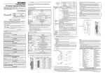
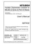
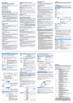
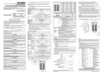
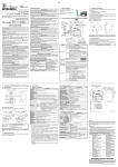
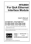
User's Manual
MODEL
CL2Y8-TP1S2-U
MODEL
13JP24
Number
IB(NA)-0800257-B(0506)MEE
© 2003 MITSUBISHI ELECTRIC CORPORATION
zSAFETY PRECAUTIONSz
(Read these precautions before using.)
Please read this manual carefully and pay special attention to safety in order to handle this
product properly. Also pay careful attention to safety and handle the module properly.
These precautions apply only to Mitsubishi equipment. Refer to the user’s manual of the CPU
module to use for a description of the PLC system safety precautions.
These z SAFETY PRECAUTIONS z classify the safety precautions into two categories:
"DANGER" and "CAUTION".
DANGER
CAUTION
Procedures which may lead to a dangerous condition and cause
death or serious injury if not carried out properly.
Procedures which may lead to a dangerous condition and cause
superficial to medium injury, or physical damage only, if not
carried out properly.
CAUTION may also be linked
Depending on circumstances, procedures indicated by
to serious results.
In any case, it is important to follow the directions for usage.
Store this manual in a safe place so that you can take it out and read it whenever necessary.
Always forward it to the end user.
[DESIGN PRECAUTIONS]
DANGER
z Refer to Chapter 3 of this manual for the operation status of the module in case a
communication error occurs in the data link.
z Output could be switched on or off when a problem occurs in the remote I/O modules. So
build an external monitoring circuit that will monitor any output signals that could cause a
serious accident.
CAUTION
z Do not have control cables and communication cables bundled with or placed near by the
main circuit and/or power cables. Wire those cables at least 100mm(3.94 inch) away from
the main circuit and/or power cables. It may cause malfunction due to noise interference.
[INSTALLATION PRECAUTIONS]
CAUTION
z Use the module in an environment that meets the general specifications contained in this
manual. Using this module in an environment outside the range of the general
specifications could result in electric shock, fire, erroneous operation, and damage to or
deterioration of the product.
z Do not directly touch the module’s conductive parts.
Doing so could cause malfunction or trouble in the module.
z Tighten the module securely using DIN rail or installation screws within the specified torque
range. If the screws are too lose, the module may drop from its installation position, short
circuit, or malfunction. If the screws are too tight, the screws may be damaged, which may
cause the module to drop from its installation position or short circuit.
[WIRING PRECAUTIONS]
DANGER
z Completely turn off the externally supplied power used in the system when installing or
placing wiring. Not completely turning off all power could result in electric shock or damage
to the product.
CAUTION
z Terminal screws which are not to be used must be tightened always.
Otherwise there will be a danger of short circuit against the bare solderless terminals.
z Perform correct wiring for the module according to the product’s rated voltage and terminal
arrangement. Connecting to a power supply different from rating or miss-wiring may cause
fire and/or product failure.
z Fix terminal screws securely within the regulated torque. Loose terminal screws may cause
fire and/or malfunction. If the terminal screws are too tight, it may cause short circuit or
erroneous operation due to damage of the screws.
z Make sure foreign objects do not get inside the module, such as dirt and wire chips. It may
cause fire, product failure or malfunction.
2.1 General Specifications
The General specifications for the remote I/O module are shown in the following table.
Item
Operating ambient
temperature
Storage ambient
temperature
Operating ambient
humidity
Storage ambient
humidity
Specifications
0 to 55
-25 to 75
5 to 95%RH, non-condensing
5 to 95%RH, non-condensing
Frequency
2.2 Performance specifications
The performance specifications for the remote I/O module are shown in the following
table.
Type
Item
Number of outputs
Isolation method
Rated load voltage
Max. load current
Max. inrush current
Leakage current at OFF
Voltage drop at ON
Output method
Protect function
Response
time
OFF
8 points
Photocoupler isolation
12/24V DC
0.1A/point 0.8A/1 common
0.7A 10ms or lower
0.1mA or lower
0.3V or lower (TYP.) 0.1A, 0.6V or lower (MAX.) 0.1A
Sink type
Overload protection function, Overheat protection function
0.5ms or lower
ON
Number of stations occupied
External power Voltage
supply of the
Current
output part
consumption
Voltage
Current
Module
consumption
power supply
Current on
startup
Applicable wire size
40mA or lower (When 24V DC and all point is on)
70mA or lower (24V DC)
DIN rail installation, mounted by screws of type M4 0.7 mm
Can be installed in six directions
0.3 to 1.5mm2 (AWG22 to 16)
Connector for
CC-Link/LT interface
3)
0 1 2 3 4 5 6 7
DC24V
- +
2)
L
ON
ON
LINK
/PW
OUT
40 20 10 8 4 2
STATION NO.
1
40 20 10 8 4 2
STATION NO.
HLD
DC24V DC24V
Y0
Y1
Y2
Y3
Y4
Y5
Y6
1 0.5ms
1.5ms
Y7
DC24G DC24G COM+ COM+ COM+ COM+ COM+ COM+ COM+ COM+
L
5)
CL2Y8-TP1S2
Insulation
Load power supply/
external power supply
of the output part
CL2Y8-TP1S2
CAUTION
DC24V DC24V
Y0
Y1
Y2
Y3
Y4
Y5
1
Y6
HLD
Y7
1 +24V
2 DA
3 DB
4 24G
Terminal block
for I/O interface
1
2
3
4
5
6
7
8
9
10
11
12
13
14
15
16
17
18
19
20
DC24V
DC24G
DC24V
DC24G
Y0
COM+
Y1
COM+
Y2
COM+
Y3
COM+
Y4
COM+
Y5
COM+
Y6
COM+
Y7
COM+
DC/DC
Constant voltage
circuit
4
(0.16)
4
(0.16)
Center of DIN rail
DC24G DC24G COM+ COM+ COM+ COM+ COM+ COM+ COM+ COM+
4.5 installation hole (M4 screw)
40 (1.57)
Unit: mm (inch)
7. Cable Installation Procedure
(1) Cable Installation
Insert the tool into the square shaped hole, which corresponds to the
terminal you wish to use.
While the tool is inside the hole, insert the wire into the circular shaped hole
(as shown below).
Remove the tool from the square shaped hole, taking care not to remove the
wire.
After the wire has been clamped, gently pull the wire to confirm that it is
secure.
Square shaped hole
Circular shaped hole
Tool *2
Wire
*1: Take care that the wire strip length
is between 8mm to 11mm.
If the wire strip length is too long,
this will expose the bare wire, which
increases the risk of electric shock
or short circuit.
If the wire strip length is too short,
this will result in the wire not being
securely attached.
*2: When mounting/removing the cable,
make sure to use the dedicated
tool, i.e., a tool dedicated to spring
clamp terminal block, and insert the
tool vertically into the hole.
If a general slotted screwdriver is
used instead of the dedicated tool,
or the tool is not vertically inserted,
the spring clamp terminal part or
terminal block resin part might be
broken.
(2) Cable removal
Insert the tool into the corresponding square shaped hall until it stops.
Pull the wire out of the hall completely.
Warranty
Mitsubishi will not be held liable for damage caused by factors found not to be the cause of
Mitsubishi; machine damage or lost profits caused by faults in the Mitsubishi products;
damage, secondary damage, accident compensation caused by special factors unpredictable
by Mitsubishi; damages to products other than Mitsubishi products; and to other duties.
For safe use
y This product has been manufactured as a general-purpose part for general industries, and
has not been designed or manufactured to be incorporated in a device or system used in
purposes related to human life.
y Before using the product for special purposes such as nuclear power, electric power,
aerospace, medicine or passenger movement vehicles, consult with Mitsubishi.
y This product has been manufactured under strict quality control. However, when installing
the product where major accidents or losses could occur if the product fails, install
appropriate backup or failsafe functions in the system.
Country/Region Sales office/Tel
U.S.A
Mitsubishi Electric Automation Inc.
500 Corporate Woods Parkway Vernon
Hills, IL 60061
Tel : +1-847-478-2100
Brazil
MELCO-TEC Rep. Com.e Assessoria
Tecnica Ltda.
Rua Correia Dias, 184,
Edificio Paraiso Trade Center-8 andar
Paraiso, Sao Paulo, SP Brazil
Tel : +55-11-5908-8331
Germany
Mitsubishi Electric Europe B.V. German
Branch
Gothaer Strasse 8 D-40880 Ratingen,
GERMANY
Tel : +49-2102-486-0
U.K
Mitsubishi Electric Europe B.V. UK
Branch
Travellers Lane, Hatfield, Herts., AL10
8XB,UK
Tel : +44-1707-276100
Italy
Mitsubishi Electric Europe B.V. Italian
Branch
Centro Dir. Colleoni, Pal. Perseo-Ingr.2
Via Paracelso 12, 20041 Agrate B.,
Milano, Italy
Tel : +39-039-6053344
Spain
Mitsubishi Electric Europe B.V. Spanish
Branch
Carretera de Rubi 76-80
08190 Sant Cugat del Valles,
Barcelona, Spain
Tel : +34-93-565-3131
France
Mitsubishi Electric Europe B.V. French
Branch
25 Boulevard des Bouvets, F-92741
Nanterre Cedex, France
TEL: +33-1-5568-5568
South Africa
Circuit Breaker Industries LTD.
Tripswitch Drive, Elandsfontein Gauteng,
South Africa
Tel : +27-11-928-2000
Country/Region Sales office/Tel
Hong Kong
Ryoden Automation Ltd.
10th Floor, Manulife Tower, 169 Electric
Road, North Point, HongKong
Tel : +852-2887-8870
China
Ryoden Automation Shanghai Ltd.
3F Block5 Building Automation
Instrumentation Plaza 103 Cao Bao Rd.
Shanghai 200233 China
Tel : +86-21-6120-0808
Taiwan
Setsuyo Enterprise Co., Ltd.
6F., No.105 Wu-Kung 3rd.RD, Wu-Ku
Hsiang, Taipei Hsine, Taiwan
Tel : +886-2-2299-2499
Korea
HAN NEUNG TECHNO CO.,LTD.
1F Dong Seo Game Channel Bldg.,
660-11, Deungchon-dong Kangsec-ku,
Seoul, Korea
Tel : +82-2-3660-9552
Singapore
Mitsubishi Electric Asia Pte, Ltd.
307 Alexandra Road #05-01/02,
Mitsubishi Electric Building
Singapore 159943
Tel : +65-6473-2308
Thailand
F. A. Tech Co.,Ltd.
898/28,29,30 S.V.City Building,Office
Tower 2,Floor 17-18 Rama 3 Road,
Bangkpongpang, Yannawa,
Bangkok 10120
Tel : +66-2-682-6522
Indonesia
P.T. Autoteknindo SUMBER MAKMUR
Jl. Muara Karang Selatan Block a Utara
No.1 Kav. No.11 Kawasan Industri/
Pergudangan Jakarta - Utara 14440
Tel : +62-21-663-0833
India
Messung Systems Put,Ltd.
Electronic Sadan NO:111 Unit No15,
M.I.D.C BHOSARI,PUNE-411026, India
Tel : +91-20-712-2807
Australia
Mitsubishi Electric Australia Pty. Ltd.
348 Victoria Road, PostalBag, No 2,
Rydalmere, N.S.W 2116, Australia
Tel : +61-2-9684-7777
6)
[Pin numbers and signal names]
4 3 2 1
CAUTION
z When disposing of this product, treat it as industrial waste.
5. Wiring
16 mm or larger
1)
Clamping torque range
0.824 to 1.11 N y m
0.425 to 0.575 N y m
(2) When using a DIN rail, attach the DIN rail after taking the following items into
consideration:
(a) Applicable DIN rail types (conform to JIS C 2812)
TH35-7.5Fe
TH35-7.5Al
(b) Interval between the DIN rail’s installation screws
Tighten the screws using a pitch of 200mm (7.87in.) or less when attaching a
DIN rail.
(3) To attach the remote I/O module to the DIN rail, press the centerline area of the
DIN rail hook beneath the module until a click is heard.
(4) Maintain some distance between the module and other components and parts, 10
mm from the top and 50mm (1.97in.) from the bottom of the module, in order to
improve ventilation and to make replacement of the module easy if a remote I/O
module is installed on a board.
(5) Install the remote I/O module on a level surface.
If the surface is uneven, unnecessary force is applied to the printed circuit board,
causing malfunctions.
This section explains the names of the components for the remote I/O module.
4)
OUT
40 20 10 8 4 2
STATION NO.
Wire strip length:
8mm to 11mm *1
3. Part Names
PW L RUN L ERR.
ON
LINK
/PW
Hook for installing the module on a DIN rail.
Screw location
Module mounting screw (M4 screw)
Terminal block mounting screw (M3 screw)
DC type noise voltage 500Vp-p, noise width 1µs, noise carrier frequency 25
Noise durability
to 60Hz (noise simulator condition)
First transient/noise burst IEC 61000-4-4 : 1kV
500V AC for 1 minute between primary (external DC terminal) and secondary
Withstand voltage
(internal circuit)
10MΩ or more between primary (external DC terminal) and secondary
Insulation resistance
(internal circuit) when measured with a 500V DC insulation resistance tester
Protection class
IP2X
Weight
0.12kg
I/O part connection method
2-piece 20-point spring clamp terminal block
Module installation method
0 1 2 3 4 5 6 7
Connector for CC-Link/LT communication line and module power supply.
Terminal block for connecting output signal, load power supply, and
external power supply of the output part.
10
(0.39)
CL2Y8-TP1S2
PW L RUN L ERR.
(1) Tighten the terminal screws for the module to the specified torque shown below.
Insufficient tightening torque could result in shorts, failures or malfunction.
0.5ms or lower (Resistive load)
Zener diode
8 points/1 common (terminal block 2-wire type)
In 4-point mode: Occupies 2 stations
In 8 or 16-point mode: Occupies 1 station
10.2 to 28.8V DC (ripple ratio : within 5%)
15mA (24V DC, when all points are ON)
Not including external load current
24V DC (-15 to +20%) (ripple ratio : within 5%)
ON OFF
Surge suppression
Common wiring method
4) Connector for
CC-Link/LT
interface
5) Terminal block
for I/O interface
6) Hook for
DIN rail
4.5
(0.18)
4. Handling Precautions
CL2Y8-TP1S2
[STARTING AND MAINTENANCE PRECAUTIONS]
[DISPOSAL PRECAUTIONS]
Sweep count
*1 : This indicates the section of the power supply to which the equipment is assumed to be
connected between the public electrical power distribution network and the machinery within
premises. Category II applies to equipment for which electrical power is supplied from fixed
facilities.
The surge voltage withstand level for up to the rated voltage of 300 V is 2500 V.
*2 : This index indicates the degree to which conductive material is generated in terms of the
environment in which the equipment is used.
Pollution level 2 is when only non-conductive pollution occurs. A temporary conductivity caused
by condensing must be expected occasionally.
*3 : It can also be used in an environment other than on the control panel if the conditions such as
usage ambient temperature and humidity are satisfied.
DANGER
z Do not disassemble or modify the module. Doing so may cause failure, malfunction, injury,
or fire.
z Do not drop or apply any strong impact to the module. Doing so may damage the module.
z Completely turn off the externally supplied power used in the system before mounting or
removing the module. Not doing so could result in damage to the product.
z Before touching the module, always touch grounded metal, etc. to discharge static electricity
from the human body, etc. Not doing so can cause the module to fail or malfunction.
Amplitude
0.075mm
(0.003in.)
———
0.035mm
(0.001in.)
———
Under
———
Conforming intermittent 10 to 57Hz
10 times each
to JIS
vibration 57 to 150Hz
9.8m/s2
Vibration resistance
in X, Y, Z
B 3502, IEC
directions (for
Under
61131-2
10 to 57Hz
———
80 min.)
continuous
vibration 57 to 150Hz
4.9m/s2
Conforming to JIS B 3502,
Shock resistance
IEC 61131-2 (147 m/s2, 3 times in each of 3 directions X, Y, Z)
Operating ambience
No corrosive gases
Operating altitude
2000m (6562ft.) max.
Installation location
Inside control panel *3
Overvoltage
II max.
category *1
Pollution level *2
2 max.
[STARTING AND MAINTENANCE PRECAUTIONS]
z Do not touch terminals when the power is on. Doing so could cause an electric shock.
z Switch off all phases of the externally supplied power used in the system when cleaning the
module or retightening the terminal or module mounting screws. Not doing so could result
in electric shock.
Acceleration
4.5 5.1 elongated mounting hole (M4 screw)
69(2.72)
60.5(2.38) 0.4(0.02)
4
(0.16)
22 (0.87)
2. Specifications
6. External Dimensions
0.2 (0.01)
Thank you very much for purchasing this product.
Please read this manual thoroughly before starting to use the product and
handle the product properly.
This user’s manual explains specifications and names of individual parts of the
CL2Y8-TP1S2 type CC-Link/LT remote I/O module (hereinafter abbreviated as
remote I/O module).
Description
Confirmation details
On: Power supply on.
PW
Off: The power supply is turned off or the voltage drop is too
large.
On: Normal communication.
L RUN
Off : Communication cutoff
(time expiration error).
On: Indicates that a communication data error has occurred
or the setting switch is outside the allowable range.
Flicker at regular intervals:
Indicates that the setting switch has been changed while
current is being conducted.
(The module continues to operate even while the LED is
L ERR.
flickering. The changed settings will be reflected when
the power has been restored.)
Flicker at irregular intervals:
Indicates that the terminal resistor is left unconnected or
that the module or connection cable are affected by
noise.
Off: Normal communication.
Displays the ON/OFF status of the output (turned on in the
0 to 7
ON status and turned off in the OFF status).
2) Output hold
Specifies whether to maintain or turn off the output of the remote I/O
setting switch
module in case the communication stops.
(SW8)
The switch is set to OFF at shipment from the factory.
ON: Maintain output
OFF: Turn output off
3) Station number Select "10", "20" or "40" to set the ten’s place of the station number.
setting switches Select "1","2","4" or "8" to set the one’s place of the station number.
(SW1 to 7)
All switches are set to OFF at shipment from the factory.
Always set the station number within the range of 1 to 64.
A setting error occurs and "L ERR." LED flickers if the value outside the
range 1 to 64 is set.
(Example) Set the switches as below when setting the station number to 32:
Station
Ten’s place
One’s place
number
40
20
10
8
4
2
1
32
OFF
ON
ON
OFF
OFF
ON
OFF
LED name
49 (1.93)
CL2Y8-TP1S2
CC-Link/LT Remote I/O Module
No.
Item
1) Operating
status indicator
LEDs
41(1.61)
1. Overview
LINK/PW
Pin No.
1
2
3
4
Signal
name
+24V
DA
DB
24G
[Terminal numbers and signal names]
1
3
5
DC24V DC24V
2
4
7
Y0
9
11
Y2
Y1
6
8
15
13
Y3
10
Y4
12
17
19
Y6
Y5
14
16
All COM+ and DC24V terminals are connected within the module (common).
The power to the module is supplied via the power adapter.
Y7
18
20
DC24G DC24G COM+ COM+ COM+ COM+ COM+ COM+ COM+ COM+
HEAD OFFICE : 1-8-12, OFFICE TOWER Z 14F HARUMI CHUO-KU 104-6212, JAPAN
NAGOYA WORKS : 1-14, YADA-MINAMI 5-CHOME, HIGASHI-KU, NAGOYA, JAPAN
When exported from Japan, this manual does not require application to the Ministry
of Economy, Trade and Industry for service transaction permission.
Specifications subject to change without notice.
Printed in Japan on recycled paper.