1
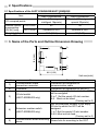
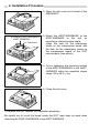
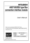
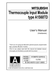
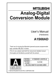
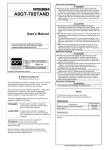
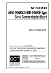
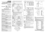
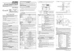
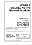
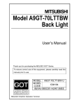
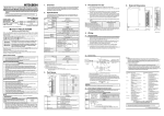
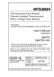
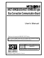
A9GT-50WQBUSS/A9GT-50WBUSS type Bus Connection Communication Board User’s Manual Thank you for buying the MELSEC-GOT Series Prior to use, please read both this manual and detailed manual thoroughly and familiarize yourself with the product. MODEL A9GT-50W(Q)BUSS-U MODEL 1DM112 CODE IB(NA)-0800185-B(0406)MEE MITSUBISHI Graphics Operation Terminal z SAFETY PRECAUTIONS z (Always read before starting use) When using Mitsubishi equipment, thoroughly read this manual and the associated manuals introduced in the manual. Also pay careful attention to safety and handle the module properly. These precautions apply only to the installation of Mitsubishi equipment and the wiring with the external device. Refer to the user’s manual of the CPU module to be used for a description of the PLC system safety precautions. These SAFETY PRECAUTIONS classify the safety precautions into two categories: "DANGER" and "CAUTION". DANGER Procedures which may lead to a dangerous condition and cause death or serious injury if not carried out properly. CAUTION Procedures which may lead to a dangerous condition and cause superficial to medium injury, or physical damage only, if not carried out properly. CAUTION may also Depending on circumstances, procedures indicated by be linked to serious results. In any case, it is important to follow the directions for usage. Store this manual in a safe place so that you can take it out and read it whenever necessary. Always forward it to the end user. [DESIGN PRECAUTIONS] DANGER z Do not bundle control lines or communication wires together with main circuit or power lines, or lay them close to these lines. As a guide, separate the lines by a distance of at least 100 mm (3.94 inch) otherwise malfunctions may occur due to noise. [INSTALLATION PRECAUTIONS] DANGER z Before mounting or dismounting this module to or from the GOT, always shut off GOT power. Not doing so can cause a module failure or malfunction. z Before connecting the Communication cable to this module, always shut off GOT power. Not doing so can cause a malfunction. [INSTALLATION PRECAUTIONS] CAUTION z Use this module in the environment given in the general specifications of the GOT User's Manual. Not doing so can cause an electric shock, fire, malfunction or product damage or deterioration. z Insert the communication board securely into the GOT connector. After it has been inserted, check to make sure that it is not being lifted up. A faulty connection can lead to faulty input or output. z When installing this unit to the GOT, fit it to the connection interface of the GOT and tighten the mounting screws in the specified torque range. Undertightening can cause a drop, failure or malfunction. Overtightening can cause a drop, failure or malfunction due to GOT or screw damage. z When mounting the communication board, take care not to become injured by the components that are installed or surrounding materials. z When mounting the communication board, remove any static electricity accumulated on your body before engaging in work. Otherwise, this may result in damage to the board. [WIRING PRECAUTIONS] CAUTION z Insert and fit the bus connection cable into the connector of the module to be connected until it "clicks". After fitting, check for looseness. Not doing so can cause a malfunction due to a connection fault. [STARTUP AND MAINTENANCE PRECAUTIONS] DANGER z Do not change the switch setting during to the be in operation. Doing so can cause a malfunction. z Before starting cleaning, always shut off GOT power. Not doing so can cause a module failure or malfunction. [STARTUP AND MAINTENANCE PRECAUTIONS] CAUTION z Do not disassemble or modify any module. This will cause failure, malfunction, injuries, or fire. z Do not touch the conductive areas and electronic parts of this module directly. Doing so can cause a module malfunction or failure. z Always secure the cables connected to the module, e.g. run them in conduits or clamp them.Not doing so can cause module or cable damage due to dangling, moved or accidentally pulled cables or can cause a malfunction due to a cable contact fault. z Do not hold the cable part when unplugging any cable connected to the module. Doing so can cause module or cable damage or a malfunction due to a cable contact fault. z Always make sure to touch the grounded metal to discharge the electricity charged in the body, etc., before touching the module. Failure to do so may cause a failure or malfunctions of the module. [DISPOSAL PRECAUTIONS] CAUTION z Dispose of this product as industrial waste. Manuals Relevant Manuals For relevant manuals, refer to the PDF manual stored within the drawing software. 2001 MITSUBISHI ELECTRIC CORPORATION 1. Overview This user's manual describes the A9GT-50WQBUSS Bus connection communication board (hereafter referred to as the "A9GT-50WQBUSS")/A9GT-50WBUSS Bus connection communication board (hereafter referred to as the "A9GT-50WBUSS"). The A9GT-50WQBUSS/A9GT-50WBUSS is mounted on the A956WGOT to PLC system of the via a bus. The A9GT-50WQBUSS is a communication board used for QCPU (Q mode) bus connection. The A9GT-50WBUSS is a communication board used for A/QnA/motion controller CPU bus connection. A956WGOT + A9GT-50WQBUSS/A9GT-50WBUSS PLC CPU When bus connection communication board is used, it is necessary to set the increased number of stages and the I/O slot number. The setting method varies as shown below depending on the bus connection communication board used. Type Setting method A9GT-50WQBUSS Set by [Setup] of the GOT utility function. Set by the extension stage switch and I/O slot switch of the A9GT-50WBUSS A9GT-50WBUSS. Refer to the GOT-A900 Series User's Manual(GT Works Version5/GT Designer Version5 compatible Connection System Manual) for the configuration of the bus connection system and setting. After opening the box, check that the following items are present. Description Quantity A9GT-50WQBUSS or A9GT-50WBUSS 1 Communication board Mounting screw 3 2. Specifications 2.1 Specifications of the A9GT-50WQBUSS/A9GT-50WBUSS Specifications Item A9GT-50WQBUSS A9GT-50WBUSS 16points (I/O assignment: 32points (I/O assignment: I/O occupied points intelligent 16points) special 32points) Internal current CPU 5VDC 42 36 consumption GOT 5VDC Included in GOT Included in GOT (DC5V) [mA] Weight [g] (lb) 49.6 (0.11) 53 (0.12) 3. Name of the Parts and Outline Dimension Drawing 5) 97.8 (3.85) 5) 1) 2) 5) 3) 4) 88.9 (3.50) Unit:mm(inch) Number 1) 2) Name Communication cable connection connector Connector Description Connector for connection of communication cable Connector for connection to the GOT Set the empty I/O slot to which the GOT will be assigned. 0 to 7 :Set the empty I/O slot number. 8,9 :Must not be used. (Factory-set to 0) Set the extension number of the empty I/O slot to which the GOT will be assigned. 1 to 7:Set the empty I/O slot number. 0,8,9 :Must not be used. (Factory-set to 0) 3) I/O slot switch (A9GT-50WBUSS only) 4) Extension number switch (A9GT-50WBUSS only) 5) Communication board mounting Screw hole for mounting to the GOT screw 4. Installation Procedure 1) Open the slot cover on the back of the A956WGOT. a) Insert the A9GT-50WQBUSS /A9GT-50WBUSS. b) Push down. 2) Mount the A9GT-50WQBUSS or the A9GT-50WBUSS in the slot for mounting a communication board. (Align the hole for the attachment screw on the transmission board with the hole for the attachment screw on the transmission board of the GOT main module, then attach.) 3) Fix by tightening the mounting screws of the A9GT-50WQBUSS or the A9GT50WBUSS within the specified torque range (36 to 48 N y cm). 4) Close the slot cover. To remove the unit, reverse the installation procedure. Be careful not to touch the board inside the GOT main body by hand when mounting the A9GT-50WQBUSS or the A9GT-50WBUSS. Warranty Mitsubishi will not be held liable for damage caused by factors found not to be the cause of Mitsubishi; machine damage or lost profits caused by faults in the Mitsubishi products; damage, secondary damage, accident compensation caused by special factors unpredictable by Mitsubishi; damages to products other than Mitsubishi products; and to other duties. For safe use y This product has been manufactured as a general-purpose part for general industries, and has not been designed or manufactured to be incorporated in a device or system used in purposes related to human life. y Before using the product for special purposes such as nuclear power, electric power, aerospace, medicine or passenger movement vehicles, consult with Mitsubishi. y This product has been manufactured under strict quality control. However, when installing the product where major accidents or losses could occur if the product fails, install appropriate backup or failsafe functions in the system. Country/Region Sales office/Tel U.S.A Mitsubishi Electric Automation Inc. 500 Corporate Woods Parkway Vernon Hills, IL 60061 Tel : +1-847-478-2100 Brazil MELCO-TEC Rep. Com.e Assessoria Tecnica Ltda. AV. Paulista 1471, Conj. 308, Sao Paulo City, Sao Paulo State, Brazil Tel : +55-11-283-2423 Germany Mitsubishi Electric Europe B.V. German Branch Gothaer Strasse 8 D-40880 Ratingen, GERMANY Tel : +49-2102-486-0 U.K Mitsubishi Electric Europe B.V. UK Branch Travellers Lane, Hatfield, Herts., AL10 8XB,UK Tel : +44-1707-276100 Italy Mitsubishi Electric Europe B.V. Italian Branch Centro Dir. Colleoni, Pal. Perseo-Ingr.2 Via Paracelso 12, 20041 Agrate B., Milano, Italy Tel : +39-039-6053344 Spain Mitsubishi Electric Europe B.V. Spanish Branch Carretera de Rubi 76-80 08190 - Sant Cugat del Valles, Barcelona, Spain Tel : +34-93-565-3131 France Mitsubishi Electric Europe B.V. French Branch 25 Boulevard des Bouvets, F-92741 Nanterre Cedex, France TEL: +33-1-5568-5568 South Africa Circuit Breaker Industries LTD. Tripswitch Drive, Elandsfontein Gauteng, South Africa Tel : +27-11-928-2000 Country/Region Sales office/Tel Hong Kong Ryoden Automation Ltd. 10th Floor, Manulife Tower, 169 Electric Road, North Point, HongKong Tel : +852-2887-8870 China Ryoden Automation Shanghai Ltd. 3F Block5 Building Automation Instrumentation Plaza 103 Cao Bao Rd. Shanghai 200233 China Tel : +86-21-6475-3228 Taiwan Setsuyo Enterprise Co., Ltd. 6F., No.105 Wu-Kung 3rd.RD, Wu-Ku Hsiang, Taipei Hsine, Taiwan Tel : +886-2-2299-2499 Korea HAN NEUNG TECHNO CO.,LTD. 1F Dong Seo Game Channel Bldg., 660-11, Deungchon-dong Kangsec-ku, Seoul, Korea Tel : +82-2-3660-9552 Singapore Mitsubishi Electric Asia Pte, Ltd. 307 ALEXANDRA ROAD #05-01/02, MITSUBISHI ELECTRIC BUILDING SINGAPORE 159943 Tel : +65-6473-2308 Thailand F. A. Tech Co.,Ltd. 898/28,29,30 S.V.City Building,Office Tower 2,Floor 17-18 Rama 3 Road, Bangkpongpang, Yannawa, Bangkok 10120 Tel : +66-2-682-6522 Indonesia P.T. Autoteknindo SUMBER MAKMUR Jl. Muara Karang Selatan Block A Utara No.1 Kav. No.11 Kawasan Industri/ Pergudangan Jakarta - Utara 14440 Tel : +62-21-663-0833 India Messung Systems Put,Ltd. Electronic Sadan NO:111 Unit No15, M.I.D.C BHOSARI,PUNE-411026 Tel : +91-20-712-2807 Australia Mitsubishi Electric Australia Pty. Ltd. 348 Victoria Road, PostalBag, No 2, Rydalmere, N.S.W 2116, Australia Tel : +61-2-9684-7777 HEAD OFFICE : 1-8-12, OFFICE TOWER Z 14F HARUMI CHUO-KU 104-6212, JAPAN NAGOYA WORKS : 1-14, YADA-MINAMI 5-CHOME, HIGASHI-KU, NAGOYA, JAPAN When exported from Japan, this manual does not require application to the Ministry of Economy, Trade and Industry for service transaction permission. Specifications subject to change without notice. Printed in Japan on recycled paper.