1
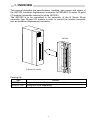
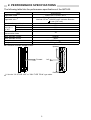
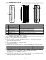
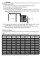
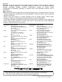
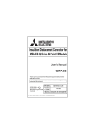
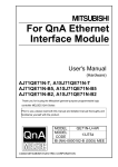
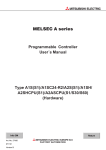
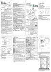
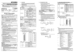
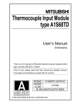
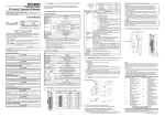
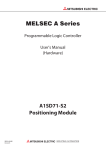
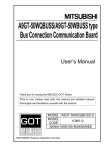
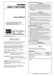
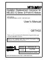
Insulation Displacement Connector for MELSEC-Q Series 32-Point I/O Module MITSUBISHI PROGRAMMABLE LOGIC CONTROLLER User’s Manual Q6TA32 Thank you for purchasing the Mitsubishi programmable logic controller MELSEC-Q series. Prior to use, please read this manual thoroughly and familiarize yourself with the product MODEL Q6TA32-U-JE MODEL CODE 13JT92 IB(NA)-0800228-B(0301)MEE © 2002 MITSUBISHI ELECTRIC CORPORATION SAFETY PRECAUTIONS (Read these precautions before using.) When using Mitsubishi equipment, thoroughly read this manual and the related manuals introduced in this manual. Also pay careful attention to safety and handle the module correctly. These SAFETY PRECAUTIONS classify the safety precautions into two categories: “DANGER” and “CAUTION”. DANGER CAUTION Procedures which may lead to a dangerous condition and cause death or serious injury, if not carried out correctly. Procedures which may lead to a dangerous condition and cause superficial to medium injury, or physical damage only, if not carried out correctly. Depending on circumstances, procedures indicated by CAUTION may also cause serious accidents. In any case, it is important to follow the directions for usage. Store this manual in a safe place so that you can take it out and read it whenever necessary. Always forward it to the end user. [DESIGN PRECAUTIONS] CAUTION Do not bunch the control wires or communication cables with the main circuit or power line, or install them close to each other. They should be installed 100 mm (3.94 inch) or more from each other. Otherwise, noise may occur and result in malfunction. [INSTALLATION PRECAUTIONS] CAUTION Use the PLC in an environment that meets the general specifications given in the CPU user's manual. Using this PLC in an environment outside the range of the general specifications may cause electric shock, fire, malfunction, and damage to or deterioration of the product. When installing this product on an I/O module, securely install it using 2 fixing screws (M2.6). Incorrect installation may cause this product to fall out, the I/O module to malfunction or similar problems to occur. A-1 [INSTALLATION PRECAUTIONS] CAUTION Always install or remove this product after switching power off externally in all phases. Otherwise, the I/O module may go down or malfunction. [WIRING PRECAUTIONS] DANGER Always start wiring after switching power off externally in all phases. Otherwise, an electric shock may occur or this product may be damaged. CAUTION When wiring this product, be sure that the terminal layout is correct and the I/O module's rated voltage is used. Connecting a power supply out of the rating or miswiring could result in fire or damage. Make sure that the applicable wires are crimped onto the terminal conductors before using this product. Be careful not to let foreign matters such as sawdust or wire chips get inside this product or the I/O module. These may cause fire, damage, or malfunction. [STARTING AND MAINTENANCE PRECAUTIONS] DANGER Do not insert or pull out the wires when power is on. It may cause a malfunction or electric shock. Always clean or retighten fixing screws after switching power off externally in all phases. Otherwise, the I/O module may malfunction. CAUTION Do not disassemble or rebuild this product. It may cause accidents, malfunction, injury, or fire. Always install or remove this product after switching power off externally in all phases. Otherwise, the I/O module may go down or malfunction. [DISPOSAL PRECAUTIONS] CAUTION When disposing this product, handle it as industrial waste. A-2 REVISIONS * The manual number is given on the bottom right of the top cover. Print Date Feb., 2002 Jan., 2003 *Manual Number Revision IB(NA)-0800228-A First edition IB(NA)-0800228-B Manual title change Pressure-Displacement Terminal Block Adaptor for MELSEC-Q Series 32-Point I/O Module This manual confers no industrial property rights or any rights of any other kind, nor does it confer any patent licenses. Mitsubishi electric Corporation cannot be held responsible for any problems involving industrial property rights which may occur as a result of using the contents noted in this manual. 2002 MITSUBISHI ELECTRIC CORPORATION CONTENTS SAFETY PRECAUTIONS ...............................................................................A-1 REVISIONS ....................................................................................................A-3 Manuals..........................................................................................................A-3 1. OVERVIEW ................................................................................................... 1 2. PERFORMANCE SPECIFICATIONS ............................................................ 2 3. NAMES OF PARTS ....................................................................................... 3 4. HANDLING INSTRUCTIONS ........................................................................ 3 5. WIRING ......................................................................................................... 4 5.1 Wiring Instructions ................................................................................... 4 5.2 External Wiring......................................................................................... 4 5.3 Wiring Procedure ..................................................................................... 5 6. EXTERNAL DIMENTIONS ............................................................................ 7 Manuals The following manual is related to this product. Please order it if necessary. Related manual Manual Name I/O Module Type Building Block User's Manual A-3 Manual Number (Model Code) SH-080042 (13JL99) 1. OVERVIEW This manual describes the specifications, handling, part names and others of the Q6TA32 insulation displacement connector for MELSEC-Q series 32-point I/O module (hereinafter referred to as the Q6TA32). The Q6TA32 is to be connected to the connector of the Q Series 40-pin connector type 32-point I/O module in order to convert the module connector into an insulation displacement connector. Q6TA32 Q Series I/O module Packing list Type Q6TA32 Q6TA32-TOL Product 32-point insulation displacement connector Wiring tool (sold separately) 1 2. PERFORMANCE SPECIFICATIONS The following table lists the performance specifications of the Q6TA32. Item Applicable model Applicable wire 2 Number of connectable wire To the left Tensile 1 strength Forward of wire Upward or downward Number of wire insertion/ disconnection times Max. allowable voltage Max. allowable current Contact resistance Weight Specifications QX41, QX71, QY41P, QY71 Polyvinyl chloride wire (twisted wire) Nominal 0.5 mm2 (AWG20) max. insulation diameter: 1.9 mm (0.07 inch) 1 35N 22N 60N 30 250VAC 3ADC 100m (327.8 feet) or less 0.08 kg (0.18 lb.) 1: Direction of tensile strength of wire Upward 20 19 B Forward Left 18 17 16 15 14 13 12 11 10 9 8 7 6 5 18 17 16 15 14 13 12 11 10 9 8 7 6 5 2 1 2 1 Downward 2: Use the "UL STYLE 1007" or "CSA TYPE TR-64" type cable. 2 20 19 A 3. NAMES OF PARTS 2) 1) 5) 7) 4) 3) 20 19 20 19 A 6) B 18 17 16 15 14 13 12 11 10 9 8 7 6 5 18 17 16 15 14 13 12 11 10 9 8 7 6 5 2 1 2 1 8) No. 1) 2) Name Line A cover Line B cover 3) Terminal number (Line A) 4) Terminal number (Line B) 5) Cover fixing screw Insulation displacement connector fixing screw Connector Tester lead-in port 6) 7) 8) Description Cover for the insulation displacement connector line A Cover for the insulation displacement connector line B Indicate the I/O module pin number A1 to A20 corresponding to the insulation displacement terminals. Indicate the I/O module pin number B1 to B20 corresponding to the insulation displacement terminals. Screw for fixing the cover (M2.6 screw) Screw for fixing the Q6TA32 to the I/O module connector (M2.6 screw) Connector for connection to the I/O module. Hole through which a tester lead is drawn for continuity check. 4. HANDLING INSTRUCTIONS (1) Do not use solid wires with this connector. (2) Do not drop the connector case and wiring tool or give them high impact since they are made of resin. (3) Do not disassemble the connector case. It may cause a failure. (4) Tighten the fixing screws and cover fixing screws within the following ranges. Screw Insulation displacement connector fixing screw (M2.6 screw) Cover fixing screw (M2.6 screw) Tightening Torque Range 21 to 28 N • cm 21 to 28 N • cm (5) When the Q6TA32 is installed to the I/O module, it is 9 mm (0.35 inch) out of the I/O module bottom. (Refer to "6. OUTLINE DRAWING".) Pay attention to the installation position. (6) The Q6TA32 cannot be used with any model that is not mentioned as the applicable model in the performance specifications. 3 5. WIRING 5.1 Wiring Instructions (1) Do not strip the insulation of the connectable wire before wiring. (2) The number of connectable wire per terminal is 1. (3) Wire the far side line B terminals first. (4) To prevent the wires from pushing the adjacent modules, connect them after pulling them toward you within the wire's tensile strength range given in the performance specifications. I/O module Forward (5) During and after wiring, do not apply loads larger than the wire's tensile strength given in the performance specifications to the wires. (6) When reusing the wire that has been connected to this connector once, cut off its insulation displacement end face in advance. 5.2 External Wiring The following table indicates the terminal number and the corresponding signal name. (When the head I/O number of the I/O module is set to 0) Input Module (QX41, QX71) Output Module (QY41P, QY71 ) Terminal Signal Terminal Signal Terminal Signal Terminal Signal number name number name number name number name B20 X00 A20 X10 B20 Y00 A20 Y10 B19 X01 A19 X11 B19 Y01 A19 Y11 B18 X02 A18 X12 B18 Y02 A18 Y12 B17 X03 A17 X13 B17 Y03 A17 Y13 B16 X04 A16 X14 B16 Y04 A16 Y14 B15 X05 A15 X15 B15 Y05 A15 Y15 B14 X06 A14 X16 B14 Y06 A14 Y16 B13 X07 A13 X17 B13 Y07 A13 Y17 B12 X08 A12 X18 B12 Y08 A12 Y18 B11 X09 A11 X19 B11 Y09 A11 Y19 B10 X0A A10 X1A B10 Y0A A10 Y1A B9 X0B A9 X1B B9 Y0B A9 Y1B B8 X0C A8 X1C B8 Y0C A8 Y1C B7 X0D A7 X1D B7 Y0D A7 Y1D B6 X0E A6 X1E B6 Y0E A6 Y1E B5 X0F A5 X1F B5 Y0F A5 Y1F B4 2 A4 2 B4 2 A4 2 B3 2 A3 2 B3 2 A3 2 1 B2 COM A2 Empty B2 12/24VDC A2 COM B1 COM A1 Empty B1 12/24VDC 1 A1 COM 1: B1 and B2 of the QY71 are used at 5/12VDC. 2: The Q6TA32 does not have the terminal number A3, A4, B3 and B4. 4 5.3 Wiring Procedure (1) Wire connection 1) Install the Q6TA32 to the I/O module with the insulation displacement connector fixing screws, loosen the cover fixing screws, and remove the covers. Covers Cover fixing screw Q6TA32 Q6TA32 I/O module 2) Insert the wire along the guide inside the Q6TA32 without a gap, push it in gently with your finger to temporarily hold it, and push it far enough with the wiring tool. Front view Wiring tool Wiring tool 20 19 Wire B 18 17 16 15 14 13 Wire Wire Wire Wire Q6TA32 Q6TA32 I/O module I/O module When wiring Line A (right side), check the numeral of Line B (left side) to confirm the terminal number to be wired. 5 3) Install the covers to the Q6TA32 and tighten the cover fixing screws. Covers Cover fixing screw Wire Wire Wire Wire Q6TA32 Q6TA32 I/O module I/O module 4) Using a tester, make a continuity check. Tester lead-in port Wire Tester lead (2) Disconnecting the wire Loosen the cover fixing screws, remove the covers, and pull the wire toward you. Cover fixing screw Covers Wire Wire Wire Wire Q6TA32 Q6TA32 I/O module I/O module 6 6. EXTERNAL DIMENTIONS (1) Q6TA32 (When mounted on an I/O module) QX41 01234567 8 9 ABCDEF 01234567 8 9 ABCDEF 20 19 90 (3.55) 37 (1.46) 98 (3.86) 9 (0.35) 93.5 (3.68) B 18 17 16 15 14 13 12 11 10 9 8 7 6 5 18 17 16 15 14 13 12 11 10 9 8 7 6 5 2 1 2 1 25 (0.99) 27.4 (1.08) (2) Q6TA32-TOL 50 (1.97) 93 (3.66) 9.5 (0.37) Unit: mm (inch) 7 20 19 A Warranty Mitsubishi will not be held liable for damage caused by factors found not to be the cause of Mitsubishi; machine damage or lost profits caused by faults in the Mitsubishi products; damage, secondary damage, accident compensation caused by special factors unpredictable by Mitsubishi; damages to products other than Mitsubishi products; and to other duties. For safe use • This product has been manufactured as a general-purpose part for general industries, and has not been designed or manufactured to be incorporated in a device or system used in purposes related to human life. • Before using the product for special purposes such as nuclear power, electric power, aerospace, medicine or passenger movement vehicles, consult with Mitsubishi. • This product has been manufactured under strict quality control. However, when installing the product where major accidents or losses could occur if the product fails, install appropriate backup or failsafe functions in the system. Country/Region Sales office/Tel U.S.A Mitsubishi Electric Automation Inc. 500 Corporate Woods Parkway Vernon Hills, IL 60061 Tel : +1-847-478-2100 Brazil MELCO-TEC Rep. Com.e Assessoria Tecnica Ltda. AV. Paulista 1471, Conj. 308, Sao Paulo City, Sao Paulo State, Brazil Tel : +55-11-283-2423 Germany Mitsubishi Electric Europe B.V. German Branch Gothaer Strasse 8 D-40880 Ratingen, GERMANY Tel : +49-2102-486-0 U.K Mitsubishi Electric Europe B.V. UK Branch Travellers Lane, Hatfield, Herts., AL10 8XB,UK Tel : +44-1707-276100 Italy Mitsubishi Electric Europe B.V. Italian Branch Centro Dir. Colleoni, Pal. Perseo-Ingr.2 Via Paracelso 12, 20041 Agrate B., Milano, Italy Tel : +39-039-6053344 Spain Mitsubishi Electric Europe B.V. Spanish Branch Carretera de Rubi 76-80 08190 - Sant Cugat del Valles, Barcelona, Spain Tel : +34-93-565-3131 France Mitsubishi Electric Europe B.V. French Branch 25 Boulevard des Bouvets, F-92741 Nanterre Cedex, France TEL: +33-1-5568-5568 South Africa Circuit Breaker Industries LTD. Tripswitch Drive, Elandsfontein Gauteng, South Africa Tel : +27-11-928-2000 Country/Region Sales office/Tel Hong Kong Ryoden Automation Ltd. 10th Floor, Manulife Tower, 169 Electric Road, North Point, HongKong Tel : +852-2887-8870 China Ryoden Automation Shanghai Ltd. 3F Block5 Building Automation Instrumentation Plaza 103 Cao Bao Rd. Shanghai 200233 China Tel : +86-21-6475-3228 Taiwan Setsuyo Enterprise Co., Ltd. 6F., No.105 Wu-Kung 3rd.RD, Wu-Ku Hsiang, Taipei Hsine, Taiwan Tel : +886-2-2299-2499 Korea HAN NEUNG TECHNO CO.,LTD. 1F Dong Seo Game Channel Bldg., 660-11, Deungchon-dong Kangsec-ku, Seoul, Korea Tel : +82-2-3660-9552 Singapore Mitsubishi Electric Asia Pte, Ltd. 307 ALEXANDRA ROAD #05-01/02, MITSUBISHI ELECTRIC BUILDING SINGAPORE 159943 Tel : +65-6473-2308 Thailand F. A. Tech Co.,Ltd. 898/28,29,30 S.V.City Building,Office Tower 2,Floor 17-18 Rama 3 Road, Bangkpongpang, Yannawa, Bangkok 10120 Tel : +66-2-682-6522 Indonesia P.T. Autoteknindo SUMBER MAKMUR Jl. Muara Karang Selatan Block A Utara No.1 Kav. No.11 Kawasan Industri/ Pergudangan Jakarta - Utara 14440 Tel : +62-21-663-0833 India Messung Systems Put,Ltd. Electronic Sadan NO:111 Unit No15, M.I.D.C BHOSARI,PUNE-411026 Tel : +91-20-712-2807 Australia Mitsubishi Electric Australia Pty. Ltd. 348 Victoria Road, PostalBag, No 2, Rydalmere, N.S.W 2116, Australia Tel : +61-2-9684-7777 HEAD OFFICE : 1-8-12, OFFICE TOWER Z 14F HARUMI CHUO-KU 104-6212, JAPAN NAGOYA WORKS : 1-14, YADA-MINAMI5, HIGASHI-KU, NAGOYA, JAPAN When exported from Japan, this manual does not require application to the Ministry of Economy, Trade and Industry for service transaction permission. Specifications subject to change without notice. Printed in Japan on recycled paper.