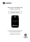
1
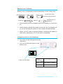
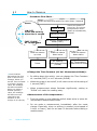
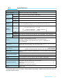
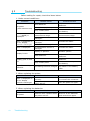
Important Safety Information The symbols for the warnings used in this manual are defined below. Classifications Danger: To Prevent Serious Injury or Death Warnings in this classification indicate danger that may result in serious injury or death if not observed. Caution: To Prevent Damage to the Product Warnings in this classification indicate risks of damage to the product that may void the product warranty if not observed. Description of Symbols △This symbol indicates a condition that requires caution (including danger). The subject of each caution is illustrated inside the triangle (e.g. the high temperature caution symbol is shown on the left). This symbol indicates a prohibition. Do not take the prohibited action shown inside or near this symbol (e.g. the disassembly prohibition symbol is shown on the left). ●This symbol indicates a mandatory action. A specific action is given near the symbol. i Danger Never bring the probe close to a flammable gas atmosphere. The heated sensor may cause a fire or explosion. Forbidden Never touch the sensor. Don’t touch Hot surface The sensor is heated during operation. Touching the heated sensor may cause burns, and may also damage the sensor itself. Do not disassemble or heat the batteries, or put them into a fire. Use properly Explosive This may cause burns and the batteries may burst. Caution Do not use the instrument in a water vapor atmosphere. Forbidden Condensed steam on the sensor will change the heat dissipation rate, resulting in inaccurate measurements. It may also cause damage to the sensor. This instrument is designed to be used in an environment with a clean air stream without any dust or foreign materials. Forbidden Foreign materials may cause damage to the sensor. Also dust or foreign materials on the sensor will impede accurate measurements. Do not apply force to the sensor. Forbidden If the sensor is deformed, the accuracy of the sensor may be affected. When measuring, ensure that the direction mark is facing into the airflow. Set up properly Forbidden ii Otherwise, the measurement may be inaccurate, as some sensors (uni-directional probes) have a specific directivity. Do not use or leave the instrument in a high temperature, high humidity or dusty environment. Do not leave this instrument under direct sunlight for a prolonged period. The instrument may not function properly out of the specified operating conditions. Do not subject the instrument or the probe to strong impacts. Forbidden Dropping the unit or placing heavy objects on it may cause damage or malfunction to the instrument. Never disassemble, modify or repair the product. Do not remodel/ disassemble Failure to observe the above may cause short circuit and/or other failure that will affect the performance. Do not pick up or carry the instrument by the probe cable. It may cause a malfunction or the wire may break. Forbidden Use properly Remove the batteries from the battery compartment when storing the instrument. Do not leave exhausted batteries in the battery compartment. When inserting batteries be sure to insert them with the polarity facing the correct direction. Failure to do so may cause battery leakage. Do not wipe the instrument with a volatile solvent. Forbidden The body may deform or deteriorate. Use a soft dry cloth to remove stains. If stains persist, soak the cloth in a neutral detergent and wipe the instrument with the soft cloth. Never use volatile solvents such as thinner or benzene. Discharge any built-up static electricity from your body before touching the instrument. Forbidden Electrified Forbidden Use properly The built-up static electricity may influence the readings and cause damage to the circuit. Regularly check the head of the probe for contamination. Impurities (such as dust) on the sensor may affect the accuracy of the measurements. To get rid of dust, use a blow blush for cameras to blow it off, or you can rinse it with water and allow it to air-dry completely. *Be sure to turn the power off before you clean it. *Never dry the probe with heat. (Heat may cause permanent damage to the sensor.) iii Do not move the main unit and the probe from a cold place to a warm place quickly. It will cause dew condensation. Forbidden Even when used in an environment within the specified operating temperature and humidity, a sudden temperature change may cause condensation. Condensation generated on the sensor may cause inaccurate measurements. Condensation on metal parts may cause rusting and lead to a malfunction. Do not touch the LCD screen with a sharp-pointed object or with excessive pressure. Forbidden Set up properly It may cause distortion of the screen or a malfunction. Also a rapid temperature change may cause a malfunction of the screen. When storing the instrument, put the instrument in the carrying case and keep it in a place with an ambient temperature of -10 to 50°C and no condensation. Do not dispose of the instrument as a household waste. Forbidden iv Please note that the disposal of the instrument and the batteries should be in line with your local or national legislation. For details, please contact your local distributor. Table of Contents §1 Part Names and Functions (Instrument) ....... 6 Part Names and Functions (Main Body) ............................... 6 Part Names and Functions (Probe) .................................... 7 §2 Preparation for Measurement ........................ 8 Installing Batteries .......................................................... 8 Battery Level Indicator .................................................... 9 Changing Units for the Readings ....................................... 9 §3 How to Measure........................................... 10 §4 Specifications .............................................. 11 §5 Troubleshooting .......................................... 12 §6 Compensation of Air Velocity Value ............. 13 §7 Warranty and After Service ......................... 14 Kanomax Limited Warranty ............................................. 14 §8 Contact Information .................................... 15 v §1 Part Names and Functions (Instrument) Part Names and Functions (Main Body) <Side> <Front> Power/Function Switch <Back> Probe Connector *Do not leave the probe inlet open except when replacing probe. Display <Enlarged view of the Power/Function Switch> Battery Case 3. Pause ON/OFF 1. Press and hold for more than 1 second. 2. FAST/SLOW/Air Temperature Power/Function Switch is a multifunction switch that can be slid up and down, and pressed. 1. Pressing will switch the power on and off. Press and hold the switch for more than 1 second until the LED indicates the change of the ON/OFF status. 2. Sliding the switch down will change the measurement mode in the following order: FAST SLOW Air Temperature FAST 3. Sliding the switch up will hold the display. Slide up, down or press the switch to continue. 6 Part Names and Functions (Instrument) Part Names and Functions (Probe) Directional Point Air Velocity Sensor *Face it windward Sensor Air Temperature (temperature compensation) Sensor *Air Velocity/Air Temperature (temperature compensation) sensors are built in. *During measurement, the whole surface of the sensor should be exposed to the wind. φ約3.3mm Grip To replace the probe, push and hold the buttons on both sides of the connector and pull the probe out. Do not remove or install the probe while the power is on. Part Names and Functions (Instrument) 7 §2 Preparation for Measurement Installing Batteries Use four AA size batteries. Make sure that the power is off before inserting the batteries. If you are using charging batteries, charge them with a special charger prior to use. <Back (Battery Case)> 1. Slide the cover of the battery case down along the rail. 2. Slide the cover until it stops, and then lift it up. + 1 2 - + 3. Insert the batteries in the order shown in the left figure, observing polarity. 4. Replace the battery cover by following the reversed procedures 1 and 2. + 3 4 - + To put the battery cover back, do not first engage the detent at the top end. Follow the above-mentioned procedure backwards to slide the cover back. If you forcibly try to click the cover onto the body, it may be broken. 8 Preparation for Measurement Battery Level Indicator Battery level is displayed as below depending on the charge left: (4.3V – 4.0V) (Lower than 4.0V) (More than 4.6V) (4.6V - 4.3V) Blinking of the indicator Replacement of Batteries Medium Sufficient Guaranteed operating voltage range of the battery is more than 4V. When battery voltage decreases to less than 4V, the display will go on and off and the power will be turned off automatically. When you are using a charging battery, recharge the battery a little early, before the 4.3V -4.0V mark is displayed. Changing Units for the Readings The units can be changed using the dip switch. You can find the dip switch in the battery box. 1 ON 2 SW No. *SW 2 is not used. Units m/s °C FPM °F 1 OFF (factory default) ON Preparation for Measurement 9 §3 How to Measure - Procedure Flow Chart Push and hold the switch for more than 1 second Pause Power is on ON/OFF Press and hold for more than 1 second FAST/SLOW/ Air Temperature Display all items *When the power is turned on, air velocity measurement mode (FAST) is automatically selected. Air Velocity Measurement Mode (FAST) Slide the switch up once Slide the switch down once Slide the switch down twice Pause Air Velocity Measurement Mode (SLOW) Air Temperature Measurement Mode <Change the Time Constant (Air Vel. Measurement Mode)> *Time Constant determines the time span of the moving average. When you set the Time Constant to a larger (longer) value, the readings will become stable. When you select a smaller (shorter) value, the readings will become more responsive and sensitive to the change in air velocity. 10 By sliding down the switch, you can change the Time Constant to 1 second (FAST) or to 5 seconds (SLOW). When the power is turned off, it will return to the initial setting of 1 second (FAST). When measurement values fluctuate significantly, setting to “SLOW” will make the reading easy. <Measurement of Air temperature> Turn the power on and slide the switch down twice to enter Air Temperature Measurement Mode. Do not make a measurement immediately after the mode change. Especially, when no airflow is present (wind-speed of 0.1m/s or lower), wait for at least 30 seconds before taking a measurement. How to Measure §4 Specifications MODEL Items to Measure Range Accuracy Temperature compensation accuracy Display resolution Air Velocity Air Temperature Air Velocity Air Temperature Air Velocity Clean air of normal pressure/humidity 0.01 m/s to 20.0 m/s (20 FPM to 3940 FPM) -20 °C to 70.0 °C (-4 °F to 158 °F) ±5% of reading or ±0.015 m/s (±3 FPM), whichever is greater ±1.0 °C (±2.0 °F) ±5% of reading or ±0.015 m/s (±3 FPM), whichever is greater, (in the temperature range of 10 °C to 40 °C (50 °F to 104 °F)) 0 m/s to 9.99 m/s : 0.01m/s 10.0 m/s to 20.0 m/s : 0.1 m/s Air Velocity Air Temperature Response 6006 (minimum) 0 FPM to 1958 FPM : 2 FPM (minimum) 1960 FPM to 3940 FPM : 20 FPM 0.1 °C (0.2°F) Air Velocity Less than one second (air velocity at 1 m/s (196 FPM) : 90% response) Air Temperature Less than 30 seconds (air velocity at 1 m/s (196 FPM) : 90% response) Function (1) (2) (3) (4) Dimensions Probe : Approx. φ 6.1 (φ10.6) x 205 mm (φ 3.3 x approx. 1.5 m for cable) Main body : Approx.60(W) x 120 (L) X 34 (H) mm Power Source Four AA batteries…manganese batteries, alkali batteries or charging batteries (Ni-Cd, Ni-MH) (Please purchase a special charger if you use charging batteries) Battery Life Operating Environment Battery Life Indicator (4 levels) FAST / SLOW (1 second or 5 second moving average) Change of units using dip switch (m/s and °C FPM and °F) Hold Display Approx. 4 hours (continuous measurement at 1 m/s air velocity using manganese batteries) Main Body: 5 °C to 40 °C (41 °F to 104°F), with no visible condensation Probe: -20.0 °C to 70 °C (-4 °F to 158°F), with no visible condensation Storage Temperature Range -10 °C to 50 °C (14 °F to 122°F), with no visible condensation Weight Approx. 180 g (including batteries) Standard Accessories Manganese AA size batteries (for test purpose)…………………………………… Operation manual (this volume) ………………………………………………………… Carry case ………………………………………………………………………………………… Extension rod (166mm to 909 mm) ……………………………………………………… Option Spare probe 4 1 1 1 *Supplied batteries are for tests. If the batteries are weak, replace them with new ones for accurate measurement. Specifications 11 §5 Troubleshooting Before asking for repair, check the items below. 1. Under normal conditions: Problems No power. (LCD remains unlit) Possible Cause Dead batteries. Replace them with new batteries. Wrong battery polarity. Insert them correctly. Dirty contact point. “----” (OVER) is displayed. “E01” is displayed or “0.00” display remains unchanged. “E02” is displayed. Used beyond the measurement range. Air velocity sensor is damaged. Air velocity sensor is damaged. Contact the dealer. Contact the dealer. Contact the dealer. Air temperature sensor is damaged. Contact the dealer. Display is “paused”. Release “pause”. Weak batteries. Unit of the readings is different. Clean the contact point of the battery. Use it within the measurement range. Probe cable is damaged. Display frozen. Display goes on and off. Corrective Action Weak batteries. Dirty contact point. Unit setting has been changed. Replace them with new batteries. Replace them with new batteries. Clean the contact point of the battery. Change the unit using the dip switch in the battery case. 2. When replacing the probe: Problem “E01” is displayed or “0.00” display remains unchanged. Possible Cause Connector is not connected correctly. Probe was replaced while the power was on. Corrective Action Turn the power off and re-connect the connector. Turn the power on again. 3. When replacing the batteries: Problem No power. 12 Troubleshooting Possible Cause Batteries were replaced while the power was on. Corrective Action Remove all the batteries and insert them again. §6 Compensation of Air Velocity Value Air temperature, humidity and pressure can influence accuracy of air velocity. <Influence of air temperature> ANEMOMASTER LITE is a hot-wire anemometer that uses heat radiation to measure wind speed, therefore, temperature compensation is needed to prevent the influence of ambient temperature. Without temperature compensation, air temperature will influence heat radiation and thus will change the readings even the actual air velocity is the same. The anemometer measures air temperature at the same time by an inner circuit called temperature compensation and automatically compensates readings of air velocity to prevent influence from air temperatures within a range of 10 °C to 40 °C. <Influence of humidity> As air velocity sensor is heated 40 °C to 50 °C above ambient temperature, it is usually not influenced by relative humidity. <Influence of atmospheric pressure> Change in pressure influences heat radiation. Compensation of atmospheric pressure is provided by using the formula below. Um= 1013 Pm × Uc Um : Actual Air Velocity[m/s] Uc: Indicating Value [m/s] Pm:Atmospheric Pressure at the Measuring Point[hPa] Compensation of Air Velocity Value 13 §7 Warranty and After Service Kanomax Limited Warranty The limited warranty set forth below is given by KANOMAX JAPAN, Inc. (hereafter referred to as “KJI”) with respect to the KANOMAX brand anemometer, and its attachment parts including probe and other accessories (hereafter referred to as “PRODUCT”) purchased directly from KJI or from and authorized distributor. Your PRODUCT, when delivered to you in new condition in its original container, is warranted against defects in materials or workmanship as follows: for a period of two (2) years from the date of original purchase, defective parts or a defective PRODUCT returned to KJI, as applicable, and proven to be defective upon inspection, will be exchanged for a new or comparable rebuilt parts, or a refurbished PRODUCT as determined by KJI. Warranty for such replacements shall not extend the original warranty period of the defective PRODUCT. This limited warranty covers all defects encountered in normal use of the PRODUCT, and does not apply in the following cases: (1) Use of parts or supplies other than the PRODUCT sold by KJI, which cause damage to the PRODUCT or cause abnormally frequent service calls or service problems. (2) If any PRODUCT has its serial number or date altered or removed. (3) Loss of damage to the PRODUCT due to abuse, mishandling, alternation, improper packaging by the owner, accident, natural disaster, electrical current fluctuations, failure to follow operation, maintenance or environmental instructions prescribed in the PRODUCT’s operation manual provided by KJI, or service performed by other than KJI. NO IMPLIED WARRANTY, INCLUDING ANY IMPLIED WARRANTY OF MERCHANTABILITY OR FITNESS FOR A PARTICULAR PURPOSE, APPLIES TO THE PRODUCT AFTER THE APPLICABLE PERIOD OF THE EXPRESS LIMITED WARRANTY STATED ABOVE, AND NO OTHER EXPRESS WARRANTY OR GUARANTY, EXCEPT AS MENTIONED ABOVE, GIVEN BY ANY PERSON OR ENTITY WITH RESPECT TO THE PRODUCT SHALL BIND KJI. KJI SHALL NOT BE LIABLE FOR LOSS OF STORAGE CHARGES, LOSS OR CORRUPTION OF DATA OR ANY OTHER SPECIAL, INCIDENTAL OR CONSEQUENTIAL DAMAGES CAUSED BY THE USE OR MISUSE OF, OR INABILITY TO USE OR CONSEQUENTIAL DAMAGES CAUSED BY THE USE OR MISUSE OF, OR INABILITY TO USE, THE PRODUCT, REGARDLESS OF THE LEGAL THEORY ON WHICH THE CLAIMS IS BASED, AND EVEN IF KJI HAS BEEN ADVISED OF THE POSSIBILITY OF SUCH DAMAGES. IN NO EVENT SHALL RECOVERY OF ANY KIND AGAINST KJI BE GREATER IN AMOUNT THAN THE PURCHASE PRICE OF THE PRODUCT SOLD BY KJI AND CAUSING THE ALLEGED DAMAGE. WITHOUT LIMITING THE FOREGOING, THE OWNER ASSUMES ALL RISK AND LIABILITY FOR LOSS, DAMAGE OF, OR INJURY TO THE OWNER AND THE OWNER'S PROPERTY AND TO OTHERS AND THEIR PROPERTY ARISING OUT OF USE OR MISUSE OF, OR INABILITY TO USE, THE PRODUCT NOT CAUSED DIRECTLY BY THE NEGLIGENCE OF KJI. THIS LIMITED WARRANTY SHALL NOT EXTEND TO ANYONE OTHER THAN THE ORIGINAL PURCHASER OF THE PRODUCT, OR THE PERSON FOR WHOM IT WAS PURCHASED AS A GIFT, AND STATES THE PURCHASER'S EXCLUSIVE REMEDY. After Service ●When you have a problem with your instrument, please check out “Troubleshooting” first. ●If that does not solve the problem, please contact your local distributor or call our service center. (See last page for "Contact Information".) ●During the warranty period, we will repair at no charge a product that proves to be defective due to material or workmanship under normal use. (See above "Kanomax Limited Warranty".) ●Repair after warranty expiration: Upon request, we will repair the instrument at the customer’s expense, if the instrument’s performance is found to be recoverable by providing the repair. ●Replacement parts are available for minimum period of five (5) years after termination of production. This storage period of replacement parts is considered as the period during which we can provide repair service. For further information, please contact your local distributor or our service center. 14 Warranty and After Service §8 Contact Information U.S.A. KANOMAX USA, INC. PO Box 372, 219 Route 206, Andover, NJ 07821 U.S.A. TEL: (800)-247-8887 / (973)-786-6386 FAX: (973)-786-7586 URL: http://www.kanomax-usa.com/ E-Mail: [email protected] JAPAN KANOMAX JAPAN, INC. 2-1 Shimizu, Suita City, Osaka 565-0805, Japan TEL: 81-6-6877-0183 FAX: 81-6-6879-5570 URL: http://www.kanomax.co.jp E-Mail: [email protected] CHINA Shenyang Kano Scientific Instrument Co., Ltd. #2610, 51 Wulihe Street Heping District Shenyang P.R.C. TEL: 86-24-23846440 FAX: 86-24-23898417 URL: http://www.kanomax.com.cn/ E-Mail: [email protected] Copyright © Kanomax Japan Inc. All rights reserved. 2012 No copying, distribution, publication, modification, or incorporation of this document, in whole or part, is permitted for commercial purposes without the express written permission of Kanomax. The contents of this document may be changed without prior notice. 01002/12.04 Contact Information 15