1
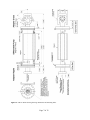
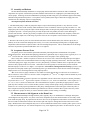
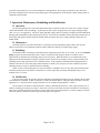
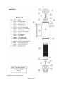
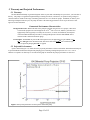
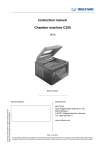
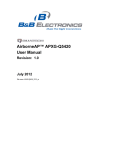
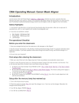
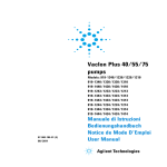
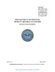
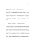
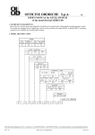
User’s Manual Differential Pump Model DP-03 XIA LLC 31057 Genstar Road Hayward, CA 94544 USA Tel: (510)-401-5760; Fax: (510)-401-5761 http://www.xia.com/ Information furnished by XIA LLC (XIA) is believed to be accurate and reliable. However, no responsibility is assumed by XIA for its use, nor for any infringements of patents or other rights of third parties which may result from its use. No license is granted by implication or otherwise under any patent or patent rights of XIA. XIA reserves the right to change specifications at any time without notice. Patents have been applied for to cover various aspects of the DP-03 Differential Pump's design. Copyright © 2010 by XIA LLC Manual #: mdo-DP03-MAN-001.0 April 12, 2011 Table of Contents 1 Theory and Experimental Parameters:.................................................................................3 1.1 Background............................................................................................................................3 1.2 Potential Synchrotron Radiation applications:.......................................................................3 1.3 Differential pumping concept:...............................................................................................3 1.4 The XIA Differential Pump:..................................................................................................4 1.5 Projected performance:..........................................................................................................5 2 Installation:...............................................................................................................................6 2.1 Support Equipment Acquisition:............................................................................................6 2.1.1 Mounting Support:..............................................................................................................6 2.1.2 Output Pump:......................................................................................................................6 2.1.3 Power Supply and High Voltage Cable:..............................................................................6 2.2 Prealignment Measurements:.................................................................................................6 2.3 Assembly and Bakeout...........................................................................................................8 2.4 Acceptance Pressure Tests:....................................................................................................8 2.5 Measurements to Aid Alignment on the Beam Line:.............................................................8 3 Operation, Maintenance, Rebuilding and Modification.......................................................9 3.1 Operation:..............................................................................................................................9 3.2 Maintenance:..........................................................................................................................9 3.3 Rebuilding:.............................................................................................................................9 3.4 Modification:..........................................................................................................................9 4 Construction and Parts List:.................................................................................................10 4.1 Construction.........................................................................................................................10 4.2 Parts List: (Refer to Figure 4.1: Assembly Drawing):.........................................................10 4.2.1 Differential Pump Body....................................................................................................10 4.2.2 Adapter Parts.....................................................................................................................10 4.2.3 Pumping Element..............................................................................................................10 4.2.4 Throttle Assemblies...........................................................................................................10 5 Warranty and Projected Performance:................................................................................12 5.1 Warranty:..............................................................................................................................12 5.2 Projected Performance:........................................................................................................12 Page 2 of 12 1 Theory and Experimental Parameters: 1.1 Background Differential pumping is a vacuum technique for providing a transition between a high pressure region and a lower pressure region via an alternating series of pumps and throttles (constrictions). See Figure 1.1. Its application to x-ray research lies in providing a windowless pressure isolation between experimental sections of low vacuum quality (e.g. 10 -6 Torr) from those which must be ultra-high vacuum (UHV, < 10-9 Torr) without using a physical barrier. Its advantage is that, having no physical barriers, it avoids all the issues which such barriers impose including excessive absorption losses in the soft x-ray and XUV regimes; mechanical problems associated with mounting and protecting such barriers against overpressures; and such thermal problems as arise on high power synchrotron radiation beamlines 1.2 Potential Synchrotron Radiation applications: The following brief list is not meant to be exhaustive but merely to indicate some of the more obvious uses to which differential pumping could be immediately applied. 1) Studies of high vapor pressure or low melting point materials. These materials are inherently UHV incompatible, so their sample chamber therefore requires isolation from the rest of the UHV system. X-ray lithography resist studies are a major example of this class of experiments. 2) Rapid turnaround studies of systems which do not require clean surfaces. If one is not doing X-ray surface studies which require UHV conditions (eg spectroscopy, diffractometry or reflectivity) then there are major advantages in experimental simplicity to be gained by operating the sample chamber at 10-6 torr rather than 10-9 torr. For example, sample changing becomes a 30 minute rather than a 3 day process if system baking is eliminated. 3) ncorporation of non-UHV mechanisms into beamlines. It is generally recognized that designing mechanisms to operate at 10-6 torr is significantly easier and cheaper than ones which must operate at 10-9 torr. The elimination of baking and the relaxation on ultimate vacuum allows the use of a variety of lubricants, feedthroughs and materials which are otherwise unacceptable. In addition, the issues of crystal changes or replacements would be greatly simplified. Such devices would require isolation from at least the beamline and possibly the sample chamber as well if UHV experiments are contemplated. The latter case would require a differential pump on both the monochromator inlet and outlet, but this would be acceptable if they were inexpensive compared to the reduction in monochromator cost. 1.3 Differential pumping concept: Differential pumping has been known for many years and is readily described in the molecular flow regime. A two stage differential pump (N=2) is shown in Figure 1.1. In the molecular flow regime the throughput q through the n th throttle is given by qn = (Pn - Pn+1)Cn n+1. The throughput of the nth pump (speed Sn) is PnSn. In addition, residual desorption or virtual leaks may create a gas load Ln in chamber n. In equilibrium, conservation of mass in each chamber creates a set of N nodal equations in Pn: (Pn-1 - Pn)Cn-1 n - (Pn - Pn+1)Cn n+1 -PnSn + Ln = 0 (1.1) Solving the N = 2 case for P3 in terms of P1 gives: C 23 C 12 P 30 C 23S 3 C 12C 23S 2 (1.2a) C 23 L2 L3 C 23S 3 C 12C 23S 2 C 23S 3 (1.2b) P 3= where P 30= Page 3 of 12 is the background pressure P3 measured in the case of negligible P1. We note that, unless the S's or L's are pressure dependent, P3 the "output" or "upstream" pressure should be linear in P1, the "input" or "downstream" pressure. Here "upstream" and "downstream" are taken from the synchrotron radiation beamline vocabulary and refer to the direction of propagation of the x-ray beam in a beamline. "Upstream' is in the direction of the storage ring x-ray source, which is typically operated at 10-10 Torr. P1 P2 C12 Input P3 C23 L2 S2 L3 Output S3 Figure 1.1: Schematic diagram of 2-stage differential pump, showing pressures (P), conductances (C), pumping speeds (S), and gas loads (L). 1.4 The XIA Differential Pump: The design concept employed in XIA Differential Pumps differs from the classical description above in two major ways. 1: Providing large line of sight clearances through the pump while keeping the overall pump length short. 2: By incorporating a pumping mechanism for the "straight-through" molecules which might otherwise pass directly from region 1 to region 3. Both are accomplished by placing distributed pumping along the line of sight through the differential pump, principally by passing the line of sight directly through the active pumping region (Figure 1.2). This design has three important characteristics. XIA Differential Pumping Section X-ray Beam P1 Input C 12 P2 L2 S2 Magnet C 23 P 3 Output L3 S 3 Figure 1.2: Schematic diagram of 2-stage differential pump using one XIA Differential Pump section and one conventional pump section. The x-ray beam passes through the active region of the XIA pumping section. 1: The Penning electrons trapped by the magnetic field in the ion pump's active pumping region have a substantial cross section for the straight through molecules and are able to remove many of them. 2: When the details of the design are optimized, the differential pump's effective pumping speed can be greatly Page 4 of 12 enhanced, which allows much larger throttle dimensions for a given overall pump length. 3: Because of the distributed pumping, the relation between input and output pressures can no longer be described by the classical model, Equation 1.2. 1.5 Projected performance: Extensive measurements on the new design established that, for many common applications, the new pump was sufficiently efficient that only a single stage was required when combined with an output pump of conventional design (ion or turbomolecular) as shown in Figure 1.2. In this configuration the output pressure P3 for N2 gas can be well described (± 50%) over 5 orders of magnitude in input pressure P1 (10-10 - 10-5 Torr) by P 3 = 5.0×10⁻⁵ C 12×C 23 0.5 0.78 P 1 P 30 S3 (1.3) where P30 is the output pressure for negligible input pressure P1. S3 is the pumping speed in liters/sec (l/s) of the conventional output pump and the throttle conductances may be computed for N2 from the molecular flow formula CN 2 29 h2 w 2 = h w L in l/s, where h and w are the height and width (in cm) of the throttle cross section and L is its length (in cm). Page 5 of 12 (1.4) 2 Installation: Installation, whether directly into final location or into a bench setup for testing, consists of the following procedures: Support Equipment Acquisition, Prealignment Measurements, Assembly and Bakeout, and Acceptance Pressure Tests. Installation into final location requires the additional step of Alignment. 2.1 Support Equipment Acquisition: The following additional pieces of equipment are required to produce a minimal completed differential pumping assembly: 1: Mounting support; 2: Output Pump; 3: Power Supply and High Voltage Cable. For acceptance pressure tests both and upstream and downstream ion gauges and controllers are required. For best results these should be calibrated and capable of measuring changes in the 10-10 Torr range with a stability and resolution of 1 x 10-11 Torr. A source of oil-free N2 is also required, preferably boil-off from a supply of LN 2 and a precision leak valve such as the Varian 951-5106. 2.1.1 Mounting Support: The XIA Differential Pump DP-03 is designed to be bolted directly to the end user’s support frame using the provided blocks at either end (see Figure 2.1). The support structure, obviously, should be designed to possess sufficient freedom of motion to allow the pump's through clearance path to be aligned with the x-ray beam and to possess sufficient rigidity to prevent motions caused by changing vacuum loads on pump body. 2.1.2 Output Pump: An output pump (S3) is required for the XIA Differential Pump to achieve its design performance. This pump is not normally supplied by XIA with the differential pumping unit, but should be acquired by the user. Its pumping speed, S 3, should be at least the value which was specified to XIA at the time of order. Increases or decreases of S3 from the design value will enhance or degrade performance according to Eqn 1.3. Typically a value of 50 to 60 liters/sec has been found to function effectively. 2.1.3 Power Supply and High Voltage Cable: The XIA Differential Pump requires an ion pump power supply which is not normally supplied by XIA, as well as a high voltage connector cable to attach it to the pump. The supply must be capable of supplying between 5.0 and 5.5 kV, negative voltage and meeting startup current needs equivalent to those found in operating a Varian 110 l/s triode ion pump. For a controller, we suggest the Varian Model 921-0066 (older unit) or Varian Multivac controller Model 929-4014 base unit plus Negative preset HV Module Model 929-4040 or equivalent. The high voltage feedthrough on the XIA Differential Pump is identical to those found on Varian pumps, so any of their cables or equivalents will suit. We suggest the Model 924-0736L (older unit) or Model 929-0770 or an equivalent. 2.2 Prealignment Measurements: Two steps are required in order to be able to pass an x-ray beam through the XIA Differential Pump. First, the two throttles must be aligned to be co-linear; second, the throttle axis so defined must be aligned with respect to the x-ray beam. The first step is carried out by XIA during final assembly of the pumping unit with the result that both the throttle tubes and their inserts are parallel to better than 0.25 mm at all points. The second step must be carried out by the user. To assist in this process 4 target sockets are attached to the XIA Differential Pump into which standard tooling balls with 1/4" stems can be inserted. Then, using mechanical or optical measurements, the user should establish and record the location of the beam axis with reference to the tooling balls using whatever alignment procedures are locally favored. The best place to record these reference dimensions may be on the pump itself. If it is necessary to remove either the Adapter Cross or Adapter Nipple in this procedure, they should be replaced prior to step II.C. Page 6 of 12 Figure 2.1: DP-03 outline drawing showing dimensions and mounting holes. Page 7 of 12 2.3 Assembly and Bakeout The XIA Differential Pump should have its output pump mounted and then be attached to whatever additional components are required. Normal UHV procedures should be followed here for roughing the system and turning on the various pumps. Following successful establishment of pumping and leak testing, the system should be prepared for baking and baked using standard local practice. If acceptance tests are planned, don't forget to attach the N 2 supply line to the variable leak valve and purge it prior to rough pumping. Two important points should be noted here: 1: The differential pump is unable to pump either input or output volumes during the bake (or any other time, for that matter). This is because of the extremely small conductances of the two throttles, which are typically less that 0.5 l/s. The output pump can be used to pump the output volume during the bake, but an input side pump should be explicitly provided to pump the input side . If such a pump is not provided, the input side will probably not achieve better than high 9's pressures after the bake. This may be perfectly acceptable, since the XIA Differential Pump will completely isolate such pressures from the output side, but the range of pressures tested to meet acceptance criteria will have to be modified accordingly. 2: Because of the relatively close fits of the Throttle Tube Inserts into the Throttle Tubes, the clearance spaces show a tendency to act like virtual leaks and pump down slowly. As a result, somewhat longer baking times (or slightly higher temperatures) than normal are required to achieve the lowest background pressures. This is normal behavior for the design and causes no particular operational difficulties once it is recognized. 2.4 Acceptance Pressure Tests: Acceptance pressure tests should be performed immediately following the bake and attainment of acceptable background pressures. While differential pumping performance is guaranteed only at a single pressure (typically P 1 = 1.0 x 10⁻⁶ Torr) the alert user will wish to determine performance across the pump's entire operating range. This is easily done. All that is required is to measure P3 for a series of P1 values from background up to the highest input pressure which can be accommodated without exceeding safe pump operating current limits. This limit will neither overload the pump power supply nor produce excessive pump heating. The latter condition can be recognized by P 3 values which rise fairly rapidly in time for a fixed P1. Such behavior will not typically be seen unless the pressure inside the differential pump is in the low 5's or higher. It is important to start with P1 at background and work up in pressure, since desorption from the pump surfaces plus virtual leaking of the type mentioned above cause the time constant for dropping output pressures to be much longer than for rising output pressures. Also, if one of the ion gauge controllers is more stable or accurate than the other, use the better one to measure P3. This is because P1 will be varied over at least 5 orders of magnitude (10-10's to 10-5's or higher) while P3 should stay in the 10's or low 9's the whole time. We recommend that a sequence of pressures on a logarithmic scale be collected for each pressure decade, particularly for pressures above 1 x 10⁻⁷. A good coarse sequence of values is 1.0, 2.0, and 4.0 in each decade. A fine sequence is 1.0, 1.5, 2.0, 3.0, 4.0, 6.0, and 8.0 in each decade. We recommend the fine sequence, particularly at higher pressures. Each point only takes a minute or two to collect and then you know exactly what the pump is doing. Included at the end of this manual is a curve of the projected performance of this pump. Plotting this data on the same figure will not only allow a direct comparison between predicted and attained performance but will also record the data in a place where they will be easy to find later in pump's life when you want to determine whether it need cleaning or rebuilding. 2.5 Measurements to Aid Alignment on the Beam Line: The XIA Differential Pump's through clearance path is typically only a few milliradians in solid angle and requires careful alignment to fully pass the x-ray beam. This task is complicated by the fact that the throttles are not readily visible from outside the pump body. In preparation for this chore, however, the prealignment measurements of Section II.B should have been made to establish the location of the clearance path with respect to tooling balls located on the exterior of the pump. Measurements to the tooling balls may now be used to establish the location of the clearance path in space as well as to adjust its roll, pitch and yaw. We will not attempt here to lay out an alignment procedure to be followed since any such Page 8 of 12 procedure will typically have to be custom designed for each application. We strongly recommend, in fact, that such a procedure be designed at the same time as the pump support is being designed to assure that the support and procedure are compatible with each other. 3 Operation, Maintenance, Rebuilding and Modification 3.1 Operation: The operating characteristics of the XIA Differential Pump are identical to those of a Varian 110 l/s triode ion pump and the unit should be treated accordingly. In particular, the unit requires an appropriate power supply and high voltage cable. See §2.1.3 for suggestions. The power supply and high voltage cable are normally not supplied with the Differential Pumping unit and should be acquired separately by the user. Those who are unfamiliar with the operating characteristics of these pumps and supplies should consult the manuals which accompany their power supply and high voltage cable for further details. 3.2 Maintenance: In normal operation no periodic maintenance is required beyond assuring that the pump remains clean, dry and otherwise unexposed to environmental conditions which could lead to shorting of its high voltage supply. 3.3 Rebuilding: The normal lifetime of ion pumps is determined by the integrated pressures they see over time. At 10 -6 torr inside the pump (as opposed to the downstream pressure, which is separated from the pump by throttle C1) lifetime will be approximately 50,000 hours and accordingly longer at lower pressures. When this lifetime is exceeded and the useful pumping rate has deteriorated an ion pump is typically rebuilt, which involves cleaning, removal of sputtered films from insulating surfaces, and replacement of its Ti cathode grid bars. In this regard the XIA Differential Pumping Element is identical to the Varian 110 l/s triode pump element and may be rebuilt by any company or facility which has experience rebuilding the latter or may be returned to XIA for rebuilding. NOTE: if either of the throttle plates are removed, whether to rebuild the unit or for any other reason, measurements should be performed to be sure that the two throttles are co-linear again after reassembly and adjusted if they are not. Similarly in Sec. 3.4 below. 3.4 Modification: If, at some future point, the clearance apertures through the XIA Differential Pump need to be modified, the procedure is not difficult to accomplish. Al that is required is to remove the Throttle Halves and replace them with others of a more appropriate size. The projected new pump performance can be calculated using Equations 1.3 and 1.4. The new Halves can either be ordered from XIA, made by machining the old ones to a new (larger) aperture size, or made by machining four entirely new Halves. In the latter case, they can be made from 6061 Aluminum or essentially any other UHV compatible material using sulfur free cutting fluids, degreased, and prepared for vacuum according to accepted local UHV practice. Dimensions can be copied from the parts to be replaced. Page 9 of 12 4 Construction and Parts List: 4.1 Construction The XIA Differential Pump has been constructed using standard UHV fabrication techniques and materials including TIG welded stainless steel vessels, machined 6061 Aluminum Throttle Halves, and vented screws for blind holes. All machining was done with sulfur free cutting fluids. 4.2 Parts List: (Refer to Figure 4.1: Assembly Drawing): XIA Part # # Rqd Name & Description Material 4.2.1 Differential Pump Body DPPB-04 1 Pump Body, DP-03 TIG welded Type 304 Stainless DPHV-01 1 High Voltage Feedthru Varian part 954-5143 or equivalent DPGA-02 1 HV Feedthru Gasket Varian part 953-5090 or equivalent Mini Flange gasket DPSC-05 6 HV Feedthru Screws Ag Plated SS Bolts, #8-32 x 3/4" DPNT-01 2 HV Attachment Nuts 10-32 SS Hex Nut DPMG-05 1 Ferrite Magnet, As per Varian 912-7006 (110 l/s ion pump size) DPSC-06 2 Magnet Mounting Bolts 1/4-20 x 1/2" SS Hex Head 4.2.2 Adapter Parts DPAC-01 1 Adapter Cross TIG welded Type 304 Stainless DPAN-01 1 Adapter Nipple TIG welded Type 304 Stainless DPGA-01 2 8" Copper Gaskets Varian part 953-5017 or equivalent DPSC-01 2 Gasket Bolt Sets 5/16-24x1-3/4" SS Ag plate 4.2.3 Pumping Element DPTR-01 1 Pumping Element Fabrication & materials as in Varian 110 l/s triode pump element DPIN-01 1 HV Lead Insulator tube Alumina ceramic 4.2.4 Throttle Assemblies DPTP-01 2 AL Throttle plate 6061 Aluminum DPTH-01 4 AL Throttle Tube Half 6061 Aluminum DPSC-02 8 Throttle Half Assembly Screws #4-40 UNC x 1/2" SS Slotted Pan Head DPSC-03 4 Vented Plate Mounting Screws #10-32 x 1/2" SS Flat Head Vented DPSC-04 8 Throttle Tube Mounting Screws #6-32 x 1/2” SS Slotted Flat Head Page 10 of 12 Figure 4.1: DP03 Assembly Drawing. Page 11 of 12 5 Warranty and Projected Performance: 5.1 Warranty: The XIA Differential Pump is guaranteed against defects in parts and workmanship for a period of 1 year from date of delivery. The pump is not guaranteed against damage resulting from abuse, carelessness, or operation using voltages or currents which are outside of the range of normally parameters for 110 l/s triode ion pumps. In addition, on delivery and following an adequate bakeout cycle, the pump will achieve the following performance levels as per the terms of sale agreed to for this instrument. Guaranteed Performance Characteristics Background Pressure: When both ends of the pump are pumped using at least 25 l/s pumps, connections to associated equipment are He leak tight at the 1x10⁻¹⁰ atm cc/sec level, and the system has been appropriately baked (typically several days at 225-250°C, see notes on installation), then all parts of the XIA Differential Pump will achieve a background pressure of better than 3x10⁻¹⁰ Torr as measured with a calibrated ionization gauge. Pressure Rise: The increase in pressure P3 at the upstream end, on application of a gas load P1 of 1 x 10⁻⁶ Torr Nitrogen at the downstream end, shall not be more than 3x10⁻¹⁰ Torr with the design value of upstream pumping F3 of 50 l/s applied. 5.2 Projected Performance: A plot is attached (Figure 5.1) which shows the projected performance of this serial number XIA Differential Pump for its specified throttle dimensions and upstream pumping speed, assuming a background pressure of 5 x 10 -11 Torr is obtained. Acceptance test data may be recorded on this graph to document the pump's performance as delivered. Figure 5.1: Projected performance for this specific differential pump Page 12 of 12