1
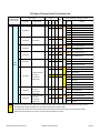
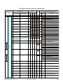
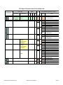
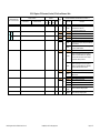
PIC-32 Pinguino OTG Connector/Function/IC Pin Cross Reference Table
PIC32-Pinguino OTG
Rev C board connectors
Pinguino Function
Main function
A6
Alternate function
Analog input 6
digitalw.c
IDE
"pin"
port
mask
pin
mask
= Bit
1
0x800
11
PIC32
Port
Microchip PIC32MX3XX/4XX Data Sheet 61143H Table 1-1
IC Pin
IC Pin Name
No
RB11
Pin 20
24
RB11
PORTB is a bidirectional I/O port.
AN11
Analog input channel 11
TDO
JTAG test data output pin
PMA12
1
A7
Analog input 7
0x400
10
Pin 21
RB10
23
Description
Parallel Master Port Address etc
RB10
PORTB is a bidirectional I/O port.
AN10
Analog input channel 10
TMS
JTAG Test mode select pin
CVREFOUT Comparator Voltage Reference Output
ICSP
1
CON1
POWER
PMA13
RST
3V3
5V
GND
Note:
External reset
(active low)
Regulated 3V3
positive lead
Regulated 5V
positive lead
Common ground
VIN
External input power
( 9-24 Vcc )
MCLR
10/26/
38/57
VDD
9/25
/41
9/25
/41
Common ground
GND
7
Parallel Master Port Address etc
Master Clear (Reset) input.
This pin is an active-low Reset to the device.
Positive supply for peripheral logic and I/O pins
(see also IC Pin 57 below)
Vss
Ground reference for logic and I/O pins
Vss
Ground reference for logic and I/O pins
This table has been compiled from information contained in a number of sources including the Olimex PIC32 Pinguino OTG User Manual, various Pinguino library files, the Microchip
PIC32MX3XX/4XX Data Sheet 61143H etc. Whilst it is hoped that this table will be useful to anyone using the particular board it is provided without any warranty, expressed or implied, as
to the correctness of the information contained in it.
PIC32-Pinguino OTG Xref Table 20 Jan 2012.xls
Prepared by mf01 for wiki.pinguino.cc
Page 1 of 7
PIC-32 Pinguino OTG Connector/Function/IC Pin Cross Reference Table
PIC32-Pinguino OTG
Rev C board connectors
A0
Pinguino Function
Main function
Input/Output 14
digitalw.c
IDE
"pin"
Alternate function
Analog input 0
port
mask
pin
mask
= Bit
1
0x02
1
A1
Input/Output 15
Analog input 1
Pin 15
A2
Input/Output 16
Analog input 2
Pin 16
Analog input 3
A4
Input/Output 18
Analog input 4
(via 33R resistor - see below)
SDA I²C data line
3
5
Note/
Warning:
A5
Input/Output 19
0x08
0x10
3
Analog input 5
(via 33R resistor - see below)
SCL I²C clock line
RB3
AN3
CN5
C2IN+
4
12
RB4
AN4
CN6
C1IN-
PORTB is a bidirectional I/O port.
Analog input channel 4
Change notification input 6
Comparator 1 Negative Input
PORTD is a bidirectional I/O port.
43
RD9
IC2
INT2
U1CTS
SDA1
44
RD10
IC3
INT3
SCL1
PMA15
PMCS2
RB3
RB4
0x200
9
RD9
Pin 18
UEXT
13
RB2
Pin 17
3
6
2
14
1
Input/Output 17
0x04
0x400
10
Pin 19
Description
PORTB is a bidirectional I/O port.
Analog input channel 1
Change notification input 3
Clock input pin for programming/ debugging
communication channel 1
Analogue voltage reference (low) input
Comparator Voltage Reference (low)
PORTB is a bidirectional I/O port.
Analog input channel 2
Change notification input 4
Comparator 2 Negative Input
SPI1 slave synchronization or frame pulse I/O.
PORTB is a bidirectional I/O port.
Analog input channel 3
Change notification input 3
Comparator 2 Positive Input
RB1
15
1
CON2
ANALOG
Microchip PIC32MX3XX/4XX Data Sheet 61143H Table 1-1
IC Pin
IC Pin Name
No
RB1
Pin 14
1
A3
PIC32
Port
RD10
AN1
CN3
PGEC1
VREFCVREFRB2
AN2
CN4
C2INSS1
Capture input 2.
External interrupt 2.
UART1 clear to send.
Synchronous serial data input/output for I2C1
PORTD is a bidirectional I/O port.
Capture input 3.
External interrupt 3.
Synchronous serial clock input/output for I2C1
Parallel Master Port Address etc
Parallel Master Port Chip Select 2 Strobe
IC Pins 43 & 21 are connected on the board via a 33R resistor. Similarly IC Pins 44 & 22 are connected on the board via a 33R resistor.
IC Pins 21 and 22 are the actual inputs to AN8 and AN9, the IC ADC inputs, used for Analog input 4 and Analog input 5 respectively.
If Analog input 4 is used Port RD9 should not be addressed directly. Similarly if Analogue input 5 is used Port RD10 should not be addressed directly.
PIC32-Pinguino OTG Xref Table 20 Jan 2012.xls
Prepared by mf01 for wiki.pinguino.cc
Page 2 of 7
PIC-32 Pinguino OTG Connector/Function/IC Pin Cross Reference Table
PIC32-Pinguino OTG
Rev C board connectors
AREF
Pinguino Function
Main function
digitalw.c
IDE
"pin"
Alternate function
port
mask
pin
mask
= Bit
1
0x01
0
PIC32
Port
Microchip PIC32MX3XX/4XX Data Sheet 61143H Table 1-1
IC Pin
IC Pin Name
No
RB0
Postive lead of the
analog reference for
analog input
RB0
16
AN0
CN2
CVREF+
PMA6
PGED1
VREF+
UEXT
GND
Common Ground
of the board
9
D13
Input/Output 13
SPI CLK clock from the SPI
module
LED1 (Green) the onboard
user LED is wired to this pin
Pin 13
7
D12
Input/Output 12
SPI IN data input from the
SPI module
MISO
Pin 12
D11
Input/Output 11
SPI OUT data output from
the SPI module
MOSI
Pin 11
D10
Input/Output 10
Select SPI select pin for the
SPI module
Pin 10
CON5
DIGITAL
8
9/25
/41
6
6
RG6
0x80
7
RG7
5
6
0x100
8
RG8
6
0x200
9
RG9
8
1
Input/Output 9
6
4
6
D9
0x40
0x4000
14
RB14
Pin 9
29
Vss
RG6
CN8
SCK2
PMA5
RG7
CN9
SDI2
PMA4
RG8
CN10
SDO2
PMA3
RG9
CN11
SS2
PMA2
RB14
AN14
U2RTS
PMA1
PMALH
D8
Input/Output 8
PIC32-Pinguino OTG Xref Table 20 Jan 2012.xls
Select SD-CARD - used as
the select pin for the SDCARD reader
1
0x2000
13
Pin 8
Prepared by mf01 for wiki.pinguino.cc
RB13
28
RB13
AN13
TDI
PMA10
Description
PORTB is a bidirectional I/O port.
Analog input channel 0
Change notification input 2
Comparator Voltage Reference (high)
Parallel Master Port Address etc
Data I/O pin for programming/ debugging
communication channel 1
Analogue voltage reference (high) input
Ground reference for logic and I/O pins
PORTG is a bidirectional I/O port.
Change notification input 8
Synchronous serial clock input/output for SPI2.
Parallel Master Port Address etc
PORTG is a bidirectional I/O port.
Change notification input 9
SPI2 data in.
Parallel Master Port Address etc
PORTG is a bidirectional I/O port.
Change notification input 10
SPI2 data out.
Parallel Master Port Address etc
PORTG is a bidirectional I/O port.
Change notification input 11
SPI2 slave synchronization or frame pulse I/O.
Parallel Master Port Address etc
PORTB is a bidirectional I/O port.
Analog input channel 14
UART2 ready to send.
Parallel Master Port Address etc
Parallel Master Port Address Latch Enable high-byte
(Multiplexed Master modes).
PORTB is a bidirectional I/O port.
Analog input channel 13
JTAG test data input pin
Parallel Master Port Address etc
Page 3 of 7
PIC-32 Pinguino OTG Connector/Function/IC Pin Cross Reference Table
PIC32-Pinguino OTG
Rev C board connectors
D7
Pinguino Function
Main function
digitalw.c
IDE
"pin"
Alternate function
Input/Output 7
port
mask
pin
mask
= Bit
3
0x800
11
Input/Output 6
D5
Input/Output 5
RTCC alarm output
8
RD8
RD8
PORTD is a bidirectional I/O port.
RD7
IC1
INT1
RTCC
RD7
Capture input 1.
External interrupt 1.
Real-Time Clock Alarm Output
PORTD is a bidirectional I/O port.
CN16
Change notification input 16.
RD6
PORTD is a bidirectional I/O port.
CN15
Change notification input 15.
42
3
0x80
7
Pin 5
55
3
Input/Output 4
Pin 4
D3
Input/Output 3
Pin 3
0x40
6
RD6
54
3
CON4
DIGITAL
PORTD is a bidirectional I/O port.
45
0x100
0x20
5
RD5
53
3
0x01
0
RD0
46
D2
D1
D0
Note/
Warning:
Input/Output 2
Input/Output 1
Input/Output 0
BUT Onboard user button is
wired on this pin
PWM 2 Pulse width
modulation output 2.
TX transmit pin for the UART
module ( serial )
PWM 1 Pulse width
modulation output 1
RX receive pin for the UART
module ( serial )
PWM 0 Pulse width
modulation output 0
(0x10)
Pin 2
(4)
RD4
52
0x08
3
RD3
Pin 1
51
RD5
PORTD is a bidirectional I/O port.
Change notification input 14.
PMRD
Parallel Master Port Read Strobe
RD0
PORTD is a bidirectional I/O port.
OC1
Output Compare output 1.
INT0
External interrupt 0.
RD4
PORTD is a bidirectional I/O port.
0x04
2
Pin 0
RD2
50
Change notification input 13.
IC5
Capture input 5.
OC5
Output Compare output 5.
PMWR
Parallel Master Port Write Strobe
RD3
PORTD is a bidirectional I/O port.
OC4
Output Compare output 4.
U1TX
3
Capture input 4.
External interrupt 4.
Parallel Master Port Address etc
Parallel Master Port Chip Select 1 Strobe
CN14
CN13
3
Description
RD11
IC4
INT4
PMA14
PMCS1
Pin 6
D4
Microchip PIC32MX3XX/4XX Data Sheet 61143H Table 1-1
IC Pin
IC Pin Name
No
RD11
Pin 7
3
D6
PIC32
Port
UART1 transmit.
RD2
PORTD is a bidirectional I/O port.
OC3
Output Compare output 3.
U1RX
UART1 receive.
IC Pins 46 & 52 are connected on the board - if RD0 or RD4 are being addressed directly and either is used as an output the other port must be set, and remain set, as an input.
The pinmask/bit details for Port RD4 (in brackets above) are only included for information and are not included in digitalw.c.
From Pinguino IDE trunk r.205/r207 (the first versions to include the PIC32 Pinguino OTG board) through to trunk r255 (the latest version when this table was last edited)
digitalw.c uses port RD0 for D2 and pwm.c, which uses OC1 on IC Pin 46, makes sure that port RD4 is set as an input.
PIC32-Pinguino OTG Xref Table 20 Jan 2012.xls
Prepared by mf01 for wiki.pinguino.cc
Page 4 of 7
PIC-32 Pinguino OTG Connector/Function/IC Pin Cross Reference Table
PIC32-Pinguino OTG
Rev C board connectors
Pinguino Function
Main function
digitalw.c
IDE
"pin"
Alternate function
1
Input/Output 22
Pin 22
2
Input/Output 23
Pin 23
3
Input/Output 24
Pin 24
4
5
6
Input/Output 25
Pin 25
Input/Output 26
Pin 26
Input/Output 27
Pin 28
7
Input/Output 28
Pin 28
8
Input/Output 29
Pin 29
9
Input/Output 30
(digitalw.c updated in
trunk r240)
10
Input/Output 31
LED2 (yellow) the onboard
user LED is wired to this pin
PIC32
Port
port
mask
pin
mask
= Bit
4
0x01
0
RE0
4
0x02
1
RE1
4
0x04
2
RE2
4
0x08
3
RE3
4
0x10
4
RE4
4
0x20
5
RE5
4
0x40
6
RE6
4
0x80
7
RE7
3
0x02
1
RD1
Pin 30
Pin 31
Microchip PIC32MX3XX/4XX Data Sheet 61143H Table 1-1
IC Pin
IC Pin Name
No
60
61
62
63
64
1
2
3
49
5
0x02
1
RF1
59
RF5
UEXT
3
CON3
11
32
RB12
12
27
RF4
UEXT
4
13
31
14
VIN
15
GND
16
5V
17
3V3
18
GND
19
AVSS
20
3.3V_AVCC
PIC32-Pinguino OTG Xref Table 20 Jan 2012.xls
9/25
/41
RF1
RF5
CN18
U2TX
SCL2
PMA8
RB12
AN12
TCK
PMA11
RF4
CN17
U2RX
SDA2
PMA9
PORTE is a bidirectional I/O port.
Parallel Master Port Data or Address/Data
PORTE is a bidirectional I/O port.
Parallel Master Port Data or Address/Data
PORTE is a bidirectional I/O port.
Parallel Master Port Data or Address/Data
PORTE is a bidirectional I/O port.
Parallel Master Port Data or Address/Data
PORTE is a bidirectional I/O port.
Parallel Master Port Data or Address/Data
PORTE is a bidirectional I/O port.
Parallel Master Port Data or Address/Data
PORTE is a bidirectional I/O port.
Parallel Master Port Data or Address/Data
PORTE is a bidirectional I/O port.
Parallel Master Port Data or Address/Data
PORTD is a bidirectional I/O port.
Output Compare output 2
UART1 ready to send.
PORTF is a bidirectional I/O port.
PORTF is a bidirectional I/O port.
Change notification input 18.
UART2 transmit.
Synchronous serial clock input/output for I2C2
Parallel Master Port Address etc
PORTB is a bidirectional I/O port.
Analog input channel 12
JTAG test clock input pin
Parallel Master Port Address etc
PORTF is a bidirectional I/O port.
Change notification input 17.
UART2 receive.
Synchronous serial data input/output for I2C2
Parallel Master Port Address etc
Vss
Ground reference for logic and I/O pins
VDD
Positive supply for peripheral logic and I/O pins
(see also IC Pin 57 below)
Vss
Ground reference for logic and I/O pins
20
Avss
Ground reference for analogue modules
19
AVDD
Positive supply for analog modules.
This pin must be connected at all times.
10/26/
38/57
9/25
/41
Prepared by mf01 for wiki.pinguino.cc
RE0
PMD0
RE1
PMD1
RE2
PMD2
RE3
PMD3
RE4
PMD4
RE5
PMD5
RE6
PMD6
RE7
PMD7
RD1
OC2
U1RTS
Description
Page 5 of 7
PIC-32 Pinguino OTG Connector/Function/IC Pin Cross Reference Table
PIC32-Pinguino OTG
Rev C board connectors
UEXT
10
Pinguino Function
Main function
Input/Output 32
(added to digitalw.c in
trunk r242)
Alternate function
UEXT_#CS
digitalw.c
IDE
"pin"
port
mask
pin
mask
= Bit
Pin 32
5
0x01
0
PIC32
Port
RF0
Microchip PIC32MX3XX/4XX Data Sheet 61143H Table 1-1
IC Pin
IC Pin Name
No
58
RB5
11
RB6
5
17
RF0
RB5
AN5
CN7
VBUSON
C1IN+
RB6
AN6
OCFA
PGEC2
ICSP
RB7
4
18
RB7
AN7
PGED2
RB8
Analog input 4
Linked via 33R resistor to
CON2 ANALOG:A4
21
RB9
Analog input 5
Linked via 33R resistor to
CON2 ANALOG:A5
22
RB15
USB_FAULT
30
RB8
AN8
U2CTS
C1OUT
RB9
AN9
C2OUT
PMA7
RB15
AN15
OCFB
CN12
PMA0
PMALL
RF3
ID
USB
V
BUS
PIC32-Pinguino OTG Xref Table 20 Jan 2012.xls
RF2 ?
Prepared by mf01 for wiki.pinguino.cc
33
34
RF3
USBID
VBUS
RF2 ?
Description
PORTF is a bidirectional I/O port.
PORTB is a bidirectional I/O port.
Analog input channel 5
Change notification input 7.
USB Host and OTG Bus Power Control Output
Comparator 1 Positive Input
PORTB is a bidirectional I/O port.
Analog input channel 6
Output Compare Fault A Input.
Clock input pin for programming/ debugging
communication channel 2
PORTB is a bidirectional I/O port.
Analog input channel 7
Data I/O pin for programming/ debugging
communication channel 2
PORTB is a bidirectional I/O port.
Analog input channel 8
UART2 clear to send.
Comparator 1 Output
PORTB is a bidirectional I/O port.
Analog input channel 9
Comparator 2 Output
Parallel Master Port Address etc
PORTB is a bidirectional I/O port.
Analog input channel 15
Output Compare Fault B Input.
Change notification input 12.
Parallel Master Port Address etc
Parallel Master Port Address Latch Enable low-byte
(Multiplexed Master modes).
PORTF is a bidirectional I/O port.
USB OTG ID Detect
USB Bus Power Monitor
PORTF is a bidirectional I/O port.
Page 6 of 7
PIC-32 Pinguino OTG Connector/Function/IC Pin Cross Reference Table
PIC32-Pinguino OTG
Rev C board connectors
Pinguino Function
Main function
Alternate function
digitalw.c
IDE
"pin"
port
mask
pin
mask
= Bit
PIC32
Port
Microchip PIC32MX3XX/4XX Data Sheet 61143H Table 1-1
IC Pin
IC Pin Name
No
35
RG3
DUSB
RG2
D+
36
37
RC12
39
VUSB
RG3
DRG2
D+
RC12
CLKI
OSC1
RC15
RC15
CLKO
OSC2
Oscillator crystal output. Connects to crystal or
resonator in Crystal Oscillator mode. Optionally
functions as CLKO in RC and EC modes.
RC13
47
RC14
48
56
57
PIC32-Pinguino OTG Xref Table 20 Jan 2012.xls
Prepared by mf01 for wiki.pinguino.cc
USB Internal Transceiver Supply.
If the USB module is not used,
this pin must be connected to VDD
PORTG input pins.
USB DPORTG input pins.
USB D+
PORTC is a bidirectional I/O port.
External clock source input. Always associated with
OSC1 pin function.
Oscillator crystal input. ST buffer when configured
in RC mode; CMOS otherwise.
PORTC is a bidirectional I/O port.
Oscillator crystal output. Connects to crystal or
resonator in Crystal Oscillator mode. Optionally
functions as CLKO in RC and EC modes. Always
associated with OSC2 pin function.
40
RC13
Description
SOSCI
CN1
RC14
SOSCO
CN0
T1CK
VCORE/
VCAP
ENVREG
PORTC is a bidirectional I/O port.
32.768 kHz low-power oscillator crystal input;
CMOS otherwise.
Change notification input 1.
PORTC is a bidirectional I/O port.
32.768 kHz low-power oscillator crystal output.
Change notification input 0.
Timer1 external clock input.
Capacitor for Internal Voltage Regulator
Enable for On-Chip Voltage Regulator
Page 7 of 7