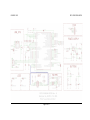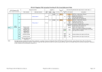
1
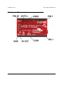
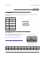
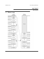
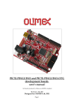
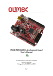
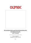
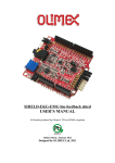
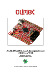
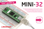
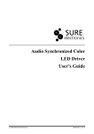
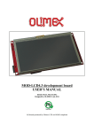
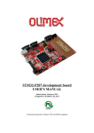
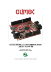
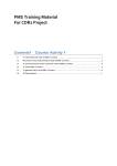
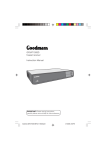
PIC32-PINGUINO-MICRO development board
USER’S MANUAL
All boards produced by Olimex LTD are ROHS compliant
Initial release, Januray 2012
Designed by OLIMEX Ltd, 2011
OLIMEX© 2012
PIC32-PINGUINO-MICRO
Disclaimer:
© 2012 Olimex Ltd. Olimex®, logo and combinations thereof, are registered trademarks of Olimex Ltd. Other
terms and product names may be trademarks of others.
The information in this document is provided in connection with Olimex products. No license, express or
implied or otherwise, to any intellectual property right is granted by this document or in connection with
the sale of Olimex products.
Neither the whole nor any part of the information contained in or the product described in this document may be
adapted or reproduced in any material from except with the prior written permission of the copyright holder.
The product described in this document is subject to continuous development and improvements. All particulars
of the product and its use contained in this document are given by OLIMEX in good faith. However all
warranties implied or expressed including but not limited to implied warranties of merchantability or fitness for
purpose are excluded.
This document is intended only to assist the reader in the use of the product. OLIMEX Ltd. shall not be liable
for any loss or damage arising from the use of any information in this document or any error or omission in such
information or any incorrect use of the product.
Thank you for purchasing the PIC32-PINGUINO-MICRO board manufactured by
Olimex!
Page 2 of 23
OLIMEX© 2012
PIC32-PINGUINO-MICRO
TABLE OF CONTENTS
SECTION 1 OVERVIEW……………………………………...………4
SECTION 2 SETTING UP THE DEVELOPMENT BOARD ……......6
SECTION 3 PIC32-PINGUINO-MICRO BOARD DESCRIPTION......9
SECTION 4 THE PIC32MX440F256H MICROCONTROLLER……..11
SECTION 5 CONTROL CIRCUITRY …………………….......………13
SECTION 6 HARDWARE ……………………………...….………….16
SECTION 7 MEMORY……………………………….….….…………19
SECTION 8 SCHEMATICS………………..........…….….....…………20
SECTION 9 REVISION HISTORY………………………………....….23
Page 3 of 23
OLIMEX© 2012
PIC32-PINGUINO-MICRO
SECTION 1
OVERVIEW
Thank you for choosing the PIC32-PINGUINO-MICRO development board from Olimex!
This document provides a User’s Guide for the Olimex PIC32-PINGUINO-MICRO
development board. As an overview, this chapter gives the scope of this document and lists
the board’s features. The document’s organization is then detailed.
1.1
Scope
The PIC32-PINGUINO-MICRO development board enables code development of
applications running on the PIC32-PINGUINO-MICRO microcontroller. This guide focuses
on the PIC32-PINGUINO-MICRO board as a development platform for the PIC32PINGUINO-MICRO device
1.2
-
-
1.3
Features
PIC32MX440F256H 80 MHz microcontroller 256KB Flash 32KB RAM
microSD card for data logging
UEXT connector which allow many existing modules like RF, ZIGBEE, GSM, GPS to
be connected
Two LEDs
One BUTTON
RESET button
USB-OTG (On-the-go) connector – so your device acts as a host allowing easier connection
All PIC ports available on 0.1" connectors
miniICSP connector 0.05"step if you do not want to use Pinguino IDE and want to program this board with PIC-ICD2-POCKET or PIC-KIT3 you should use also PIC-ICSP
convertor board, same applies for Microchip programmers.
Dimensions only 33,4mm at 54mm (1,3’’ at 2,125’’)
Similar boards
PIC32-PINGUINO-OTG is the bigger version of PIC32-PINGINO-MICRO. It features
mounted external power connector, Li-Ion battery option with built-in onboard charger, 1
LED more, wider range of power supply options, 4 mount holes making board attachment
easier.
Page 4 of 23
OLIMEX© 2012
1.4
PIC32-PINGUINO-MICRO
Organization
Each section in this document covers a separate topic, organized as follow:
Section 1 is an overview of the board usage and features
Section 2 provides a guide for quickly setting up the board and introduces the user to
Arduino/Maple/Pinguino
Section 3 contains the general board diagram and layout
Section 4 describes the component that is the heart of the board: the
PIC32MX440F256H microcontroller
Section 5 is an explanation of the control circuitry associated with the microcontroller
to reset, power and clock the board
Section 6 covers the connector pinout, peripherals and jumper description
Section 7 shows the memory map
Section 8 provides the schematics
Section 9 contains the revision history
Page 5 of 23
OLIMEX© 2012
PIC32-PINGUINO-MICRO
SECTION 2
SETTING UP THE PIC32-PINGUINOMICRO DEVELOPMENT BOARD
This section helps you set up the PIC32-PINGUINO-MICRO development board for the first
time.
Please consider first the electrostatic warning to avoid damaging the board, then discover the
hardware and software required to operate the board.
The procedure to power up the board is given, and a description of the default board behavior
is detailed.
2.1 Electrostatic Warning
The PIC32-PINGUINO-MICRO development board is shipped in a protective anti-static
package. The board must not be exposed to high electrostatic potentials. A grounding strap or
similar protective device should be worn when handling the board. Avoid touching the
component pins or any other metallic element.
2.2 Requirements
In order to set up the PIC32-PINGUINO-MICRO evaluation board, the following items are
required:
-
The PIC32-PINGUINO-MICRO development board itself
miniUSB - USB cable
Pinguino IDE
Being Arduino board PIC32-PINGUINO-MICRO can be reprogrammed via the miniUSB
using the Pinguino IDE. More info on the Pinguino IDE can be found in the following web
sites:
http://pinguino.cc/
http://wiki.pinguino.cc/index.php/IDE
Note: The board is not delivered with an ICSP debugger/programmer, which is needed if you
don’t want to use Pinguino IDE. Remember that the connector on the board is miniICSP (6
pin). You may use one of the following devices for this purpose:
-
Olimex’s PIC-ICD2-POCKET + Olimex’s PIC-ICSP
Page 6 of 23
OLIMEX© 2012
-
PIC32-PINGUINO-MICRO
Olimex’s PIC-KIT3 + Olimex’s PIC-ICSP
Also, a host-based software toolchain is required in order to program/debug the PIC32PINGUINO-MICRO board.
2.3 Powering up the board
The PIC32-PINGUINO-MICRO board is self-powered by the miniUSB port.
Additionally the board can be powered using the CON1 connector. PIN20 is GND, PIN19 is
+5V_EXT.
On powering the board LED1 must start blinking with GREEN light.
2.4 Arduino/Maple/Pinguino note
What is Arduino?
Arduino is an open-source electronics prototyping platform, designed to make the process of
using electronics in multidisciplinary projects more accessible. The hardware consists of a
simple open hardware design for the Arduino board with an Atmel AVR processor and onboard I/O support. The software consists of a standard programming language and the boot
loader that runs on the board.
Arduino hardware is programmed using a Wiring-based language (syntax + libraries), similar
to C++ with some simplifications and modifications, and a Processing-based Integrated
Development Environment (IDE).
The project began in Ivrea, Italy in 2005 aiming to make a device for controlling student-built
interaction design projects less expensively than other prototyping systems available at the
time. As of February 2010 more than 120,000 Arduino boards had been shipped. Founders
Massimo Banzi and David Cuartielles named the project after a local bar named Arduino. The
name is an Italian masculine first name, meaning "strong friend". The English pronunciation
is "Hardwin", a namesake of Arduino of Ivrea.
More information could be found at the creators web page http://arduino.cc/ and in the
Arduino Wiki http://en.wikipedia.org/wiki/Arduino
To make the story short - Arduino is easy for beginners who lack Electronics knowledge, but
also does not restrict professionals as they can program it in C++ or mix of Arduino/C++
language.
Page 7 of 23
OLIMEX© 2012
PIC32-PINGUINO-MICRO
There are thousands of projects which makes it easy to startup as there is barely no field
where Arduino enthusiasts to have not been already.
Arduino has inspired two other major derivates - MAPLE and PINGUINO. Based on 8-bit
AVR technology the computational power of Arduino boards is modest, this is why a team
from MIT developed the MAPLE project which is based on ARM7 STM32F103RBT6
microcontroller. The board have same friendly IDE as Arduino and offers the same
capabilities as hardware and software but runs the Arduino code much faster. The Maple
project can be found at http://leaflabs.com
In parallel with Arduino another project was started called PINGUINO. This project chose its
first implementation to be with PIC microcontrollers, as AVRs were hard to find in some
parts of the world like South America so it is likely to see lot of PINGUINO developers are
from that part of the world. PINGUINO project founders decided to go with Python instead
Java for processing language. For the moment PINGUINO is much more flexible than
Arduino as it is not limited to 8bit microcontrollers. Currently the IDE, which has GCC in
background, can support 8-bit PIC microcontrollers, 32bit PIC32 (MIPS) microcontrollers
and ARM7/CORTEXM3 microcontrollers which makes PINGUINO very flexible because
once you make your project you can migrate easily through different hardware platforms and
not being bound to a single microcontroller manufacturer. The PINGUINO project can be
found at: http://www.pinguino.cc.
Page 8 of 23
OLIMEX© 2012
PIC32-PINGUINO-MICRO
SECTION 3
PIC32-PINGUINO-MICRO BOARD
DESCRIPTION
Here you get acquainted with the main parts of the board. Note the names used on the board
differ from the names used to describe them. For the actual names check the PIC32PINGUINO-MICRO board itself.
For example: BUTTON (seen on the op view below) is named BUT; RESET is named RST;
etc
3.1 Layout (Top view):
Page 9 of 23
OLIMEX© 2012
PIC32-PINGUINO-MICRO
3.2 Layout (Bottom view):
Page 10 of 23
OLIMEX© 2012
PIC32-PINGUINO-MICRO
SECTION 4
THE PIC32MX440F256H MICROCONTROLLER
4.1 Features
High-Performance 32-bit RISC CPU:
• MIPS32® M4K® 32-bit core with 5-stage pipeline
• 80 MHz maximum frequency
• 1.56 DMIPS/MHz (Dhrystone 2.1) performance at
0 wait state Flash access
• Single-cycle multiply and high-performance divide
unit
• MIPS16e® mode for up to 40% smaller code size
• Two sets of 32 core register files (32-bit) to reduce
interrupt latency
• Prefetch Cache module to speed execution from
Flash
Microcontroller Features:
• Operating temperature range of -40ºC to +105ºC
• Operating voltage range of 2.3V to 3.6V
• 256K Flash memory (plus an additional
12 KB of boot Flash)
• 32K SRAM memory
• Pin-compatible with most PIC24/dsPIC® DSC
devices
• Multiple power management modes
• Multiple interrupt vectors with individually
programmable priority
• Fail-Safe Clock Monitor Mode
• Configurable Watchdog Timer with on-chip
Low-Power RC Oscillator for reliable operation
Peripheral Features:
• Atomic SET, CLEAR and INVERT operation on
select peripheral registers
• Up to 4-channel hardware DMA with automatic
data size detection
• USB 2.0-compliant full-speed device and
On-The-Go (OTG) controller
• USB has a dedicated DMA channel
• 3 MHz to 25 MHz crystal oscillator
• Internal 8 MHz and 32 kHz oscillators
• Separate PLLs for CPU and USB clocks
• Two I2C™ modules
• Two UART modules with:
- RS-232, RS-485 and LIN support
- IrDA® with on-chip hardware encoder and
decoder
• Up to two SPI modules
Page 11 of 23
OLIMEX© 2012
PIC32-PINGUINO-MICRO
• Parallel Master and Slave Port (PMP/PSP) with
8-bit and 16-bit data and up to 16 address lines
• Hardware Real-Time Clock and Calendar (RTCC)
• Five 16-bit Timers/Counters (two 16-bit pairs
combine to create two 32-bit timers)
• Five capture inputs
• Five compare/PWM outputs
• Five external interrupt pins
• High-Speed I/O pins capable of toggling at up to
80 MHz
• High-current sink/source (18 mA/18 mA) on all I/O
pins
• Configurable open-drain output on digital I/O pins
Debug Features:
• Two programming and debugging Interfaces:
- 2-wire interface with unintrusive access and
real-time data exchange with application
- 4-wire MIPS® standard enhanced JTAG
interface
• Unintrusive hardware-based instruction trace
• IEEE Standard 1149.2-compatible (JTAG)
boundary scan
Analog Features:
• Up to 16-channel 10-bit Analog-to-Digital
Converter:
- 1000 ksps conversion rate
- Conversion available during Sleep, Idle
• Two Analog Comparators
For comprehensive information on the microcontroller visit the Microchip’s web
page for a datasheet.
At the moment of writing the microcontroller datasheet can be found at the following link:
http://ww1.microchip.com/downloads/en/DeviceDoc/61143H.pdf
Page 12 of 23
OLIMEX© 2012
PIC32-PINGUINO-MICRO
SECTION 5
CONTROL CIRCUITRY
5.1 Power supply
When PIC32 is connected via a USB cable to a USB host it will take its 5V power supply
from the USB host source to power the board.
When powered and functional the current consumption is 80 mA.
Additionally the board can be powered using the CON1 connector. PIN20 is GND, PIN19 is
+5V_EXT.
5.2 Reset
PIC32-PINGUINO-MICRO reset circuit includes D2 (1N4148), R16 (4.7kΩ), R2 (33Ω), C21
(4.7nF), PIC32MX440F256H pin 7 (#MCLR) and a RESET button.
5.3 Clock
Quartz crystal Q1 8.000 MHz is connected to PIC32MX440F256H pin 39
(OSC1/CLKI/RC12) and pin 40 (OSC2/CLKO/RC15).
Page 13 of 23
OLIMEX© 2012
PIC32-PINGUINO-MICRO
SECTION 6
HARDWARE
6.1 mini ICSP
The miniICSP connector provides option to reprogram the board if you do not wish to use
Pinguino IDE.
Pin #
Signal Name
1
RESET
2
+3.3V
3
GND
4
PGED2
5
PGEC2
6
Not connected
6.2
UEXT
PIC32-PINGUINO-MICRO board has UEXT connector
and can interface Olimex's UEXT modules.
For more information on UEXT please visit:
http://www.olimex.com/dev/OTHER/UEXT.pdf
Pin
1
Signal +3.3V
2
3
4
5
6
GND
TXD
RXD
SCL
SDA
Page 14 of 23
7
8
MISO MOSI
9
10
SCK
#CS
OLIMEX© 2012
6.3
PIC32-PINGUINO-MICRO
CON1
For your convenience the pins are numbered individually on the top of the board. Please take
extra care about the numbering.
Pin #
Signal Name
1
SOSCO/T1CK/CN0/RC14
2
SOSCI/CN/RC13
3
RE0/PMD0
4
RE1/PMD1
5
RE2/PMD2
6
RE3/PMD3
7
RE4/PMD4
8
RE5/PMD5
9
RE6/PMD6
10
RE7/PMD7
11
RF1
12
RG9/#SS2/PMA2/CN11
13
IC4/PMCS1/PMA14/INT4/RD11
14
RTCC/IC1/INT1/RD8
15
CN16/RD7
16
PGED1/AN0/VREF+/CVREF+/PMA6/CN2/RB0
17
AGND
18
AREF (via J1) Pin 16
19
+5V_EXT
20
GND
Page 15 of 23
OLIMEX© 2012
6.4
PIC32-PINGUINO-MICRO
CON2
For your convenience the pins are numbered individually on the top of the board. Please take
extra care about the numbering.
Pin #
Signal Name
1
CN15/RD6
2
PMRD/CN14/RD5
3
OC5/IC5/PMWR/CN13/RD4
4
U1TX/OC4/RD3
5
U1RX/OC3/RD2
6
#U1RTS/OC2/RD1
7
AN14/#U2RTS/PMALH/PMA1/RB14
8
TDI/AN12/PMA11/RB12
9
TDO/AN11/PMA12/RB11
10
TMS/AN10/CVREFOUT/PMA13/RB10
11
AN9/C2OUT/PMA7/RB9
12
AN8/#U2CTS/C1OUT/RB8
13
AN4/C1IN-/CN6/RB4
14
AN3/C2IN+/CN5/RB3
15
AN2/C2IN-/CN4/RB2
16
PGEC1/AN1/VREF-/CVREF-/CN3/RB1
17
+3.3V
18
GND
19
+5V_VBUS
20
GND
Page 16 of 23
OLIMEX© 2012
PIC32-PINGUINO-MICRO
6.5 USB-OTG (On-The-Go)
Pin #
Signal Name
1
+5V_VBUS
2
D-
3
D+
4
USB_ID
5
GND
6.6 SD/MMC Micro card slot
A micro SD card connector is available on PIC32-PINGUINO-MICRO board, this connector
is with push-push action to insert and remove the card.
Pin #
Signal Name
1
2
3
4
5
6
7
8
MCIDAT2
MMC_#SS
MOSI
+3.3V
SCK/LED1
GND
MISO
MCIDAT1
Page 17 of 23
OLIMEX© 2012
PIC32-PINGUINO-MICRO
6.7 Jumper description
L1_E
This jumper, when closed, enables LED1.
Default state is closed.
L2_E
This jumper, when closed, enables LED2.
Default state is closed.
BUT_J
This jumper, when closed, enables BUT.
Default state is closed.
J1
When open analog voltage 3,3V reference (high).
Default state is open.
G9/F0
This jumper, when in position G9 – connects UEXT pin 10 (UEXT_#CS) to CON1-12 and
pin 8 (RG9/#SS2/PMA2/CN11) and when in position F0 – connects UEXT pin 10
(UEXT_#CS) to PIC32MX440F256H pin 58 (RF0).
Default state is in position F0.
Page 18 of 23
OLIMEX© 2012
PIC32-PINGUINO-MICRO
SECTION 7
MEMORY
7.1 Memory map
Page 19 of 23
OLIMEX© 2012
PIC32-PINGUINO-MICRO
SECTION 8
SCHEMATICS
8.1 Eagle schematic
PIC32-PINGUINO-MICRO schematic is released under Creative Commons AttributionShare Alike 3.0 United States License and can also be downloaded at our web page for
PIC32-PINGUINO-MICRO: http://olimex.com/dev/pic32-pinguino-micro.html. They are
located in HARDWARE section.
The EAGLE schematic is situated on the next page for quicker reference.
Page 20 of 23
OLIMEX© 2012
PIC32-PINGUINO-MICRO
Page 21 of 23
OLIMEX© 2012
PIC32-PINGUINO-MICRO
8.2 Physical dimensions
Page 22 of 23
OLIMEX© 2012
PIC32-PINGUINO-MICRO
SECTION 9
REVISION HISTORY
9.1
Document revision
Revision
Changes
Modified
Pages
A
Initial Creation
All
ORDER CODES:
PIC32-PINGUINO-MICRO - assembled, programmed, tested, calibrated development
boards
PIC-ICD2-POCKET + PIC-ICSP - for custom programming/debugging (if you do not wish
to use PINGUINO IDE)
PIC-KIT3 + PIC-ICSP - for custom programming/debugging (if you do not wish to use
PINGUINO IDE)
USB-MINI-CABLE - USBmini to USB-A cable
How to order?
You can order to us directly or by any of our distributors.
Check our webpage http://www.olimex.com/ for more info.
Page 23 of 23