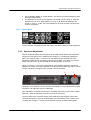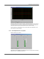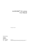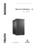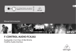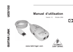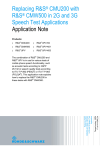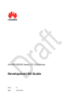
1
Generating the Noise Field for
Ambient Noise Rejection Tests
Application Note
Products:
|
R&S UPV
|
R&S UPV-K9
|
R&S UPV-K91
Thomas Lechner
Feb.09 2010 - 1GA51_0e
Application Note
This document describes how to generate
the noise field for ambient noise rejection
tests according to 3GPP TS 26.132,
sections 7.9 and 8.9.
Table of Contents
Table of Contents
Rohde & Schwarz
1
Background ............................................................................ 4
1.1
3GPP Mobile Phone Tests R&S UPV-K9, UPV-K91 .................................4
1.2
Ambient Noise Rejection (ANR) Tests .......................................................4
1.3
Requirements on the noise field.................................................................4
2
General Description ............................................................... 6
2.1
Required Equipment ....................................................................................6
2.1.1
Equipment List..............................................................................................6
2.1.2
Audio CD with Pink Noise Signal................................................................6
2.1.3
CD Player.......................................................................................................6
2.1.4
Equalizer........................................................................................................6
2.1.5
Loudspeakers ...............................................................................................6
2.1.6
Amplifier (required with passive loudspeakers) .......................................7
2.2
Test Setup .....................................................................................................7
2.2.1
Test Room .....................................................................................................7
2.2.2
Loudspeaker Arrangement..........................................................................7
2.2.3
Connections..................................................................................................8
2.3
Adjustment....................................................................................................8
2.3.1
Order of Adjustment ....................................................................................8
2.3.2
Spectrum Adjustment ..................................................................................8
2.3.3
Level Adjustment .........................................................................................8
2.3.4
Overall ...........................................................................................................9
3
Implementation with Specific Equipment .......................... 10
3.1
Equipment List............................................................................................10
3.2
Connections................................................................................................10
3.3
Adjustment..................................................................................................11
3.3.1
Settings of the Active Speakers................................................................11
3.3.2
Basic Settings of the Equalizer.................................................................11
3.3.2.1
I / O Menu ....................................................................................................11
3.3.2.2
Utility Menu .................................................................................................11
3.3.2.3
Bypass Menu ..............................................................................................12
3.3.3
Spectrum Adjustment ................................................................................12
3.3.4
Level Adjustment for one speaker............................................................13
®
Generating the Noise Field for Ambient Noise Rejection Tests
1GA51_0e 2
Table of Contents
Rohde & Schwarz
3.3.5
Checking the performance of the total setup..........................................14
3.3.6
Performing the Test ...................................................................................14
4
Literature............................................................................... 15
5
Abbreviations ....................................................................... 15
6
Ordering Information ........................................................... 15
Generating the Noise Field for Ambient Noise Rejection Tests
1GA51_0e 3
Background
1 Background
1.1 3GPP Mobile Phone Tests R&S® UPV-K9, UPV-K91
®
As a supplement to Audio Analyzer R&S UPV, Rohde & Schwarz provides options
®
®
R&S UPV-K9 (Base SW for Mobile Phone Tests) and R&S UPV-K91 (UMTS/GSM
Mobile Phone Tests) which can be used together with Universal Radio Communication
®
Tester R&S CMU200 for acoustic tests on mobile phones according to 3GPP TS
26.132.
One of the test cases specified in 3GPP TS 26.132 is Ambient Noise Rejection, which
requires equipment for generating a diffuse sound field in the test room. This
equipment is not comprised with the options. Therefore this application note explains
how to generate and adjust the required diffuse noise field with commonly available
equipment.
®
For details on the operation of the UPV-K9x software provided with option R&S
®
®
UPV-K91, see “R&S UPV-K9, R&S UPV-K91 Operating Manual”.
1.2 Ambient Noise Rejection (ANR) Tests
Ambient noise rejection is a property of a telephone in sending direction. Ambient
noise rejection tests deliver a spectrally weighted ratio between the sending sensitivity
of a telephone for speech signals (speech send sensitivity) and its sending sensitivity
for background noise (room noise sensitivity).
The ambient noise rejection test as specified in 3GPP TS 26.132 assumes that the
properties of the telephone are sufficiently time-invariant to allow separate
measurement of room noise sensitivity and speech send sensitivity. Furthermore it is
assumed that the rejection of the relatively uniform pink noise is somehow correlated
with the rejection of other types of noise like street noise and background voices.
1.3 Requirements on the noise field
According to 3GPP TS 26.132, the noise should be band limited between 100 Hz and
rd
8 kHz. The spectrum should be “pink” which means that the 3 octave levels within this
rd
frequency band should be independent of the center frequency of the 3 octave bands.
The tolerance of this spectral uniformity is defined to be ±3 dB.
The total level of the noise should be 70 dBSPL(A), equal to -24 dBPa(A) at the mouth
reference point with a tolerance of ±1 dB.
The level and spectrum at the mouth reference point is to be adjusted in absence of
the test head or HATS, respectively.
Rohde & Schwarz
Generating the Noise Field for Ambient Noise Rejection Tests
1GA51_0e 4
Background
The noise field has to be diffuse. As a proof for the diffusity of the noise field it has to
rd
be assured that the 3 octave levels between 100 Hz and 3.15 kHz (narrow band) or
between 100 Hz and 6.3 kHz (wide band) respectively, are uniform within ±3 dB within
a radius of 0.15 m around the mouth reference point (MRP).
It should be noted that this requirement can theoretically be fulfilled with a single
speaker in sufficient distance from the MRP in free field, whereas a real diffuse sound
field also exhibits random direction of the sound incidence. When measuring
telephones with directional microphones, different results of the ANR measurement
have to be expected with different direction of the noise sound incidence. Therefore it
is recommended to use at least four loudspeakers with uniform spatial distribution for
the generation of the sound field. In measurement rooms with non-anechoic conditions
a higher number of speakers may be needed to achieve the required uniformity.
To avoid interference between signals from different loudspeakers, each speaker has
to be fed with an own noise signal which is not correlated with the noise signal of any
of the other loudspeakers.
Rohde & Schwarz
Generating the Noise Field for Ambient Noise Rejection Tests
1GA51_0e 5
General Description
2 General Description
2.1 Required Equipment
2.1.1 Equipment List
F
F
F
F
F
F
F
®
Audio Analyzer R&S UPV with options UPV-K9 and UPV-K91
Audio CD(s) with pink noise signal
CD Player(s)
Equalizers
Loudspeakers
Power amplifier(s) for passive speakers
Connection cables
2.1.2 Audio CD with Pink Noise Signal
The audio CD should contain at least one sufficiently long track with two uncorrelated
pink noise signals on the two channels. An image of such a CD is provided on the
download site of this application note.
2.1.3 CD Player
In principle one CD player is required for each pair of loudspeakers. If equalizers are
used which offer a delay function of at least 250 ms, the delay can be used to decorrelate the noise signals. In this case each CD player can serve four loudspeakers.
An audio CD image with two tracks of two-channel uncorrelated band-limited pink
noise is available for download on the download site of this application note.
2.1.4 Equalizer
rd
Ideally the equalizer should be a graphic equalizer with 3 octave resolution.
Furthermore a sum gain control is required, either in the equalizer or in the power
amplifier(s). A delay function in the equalizer can be utilized to generate additional
uncorrelated noise channels from the same source (CD player), see above.
2.1.5 Loudspeakers
The loudspeaker frequency response should be sufficiently flat between 100 Hz and
8 kHz to allow equalization with the utilized equalizers. In addition to the deviation of
the loudspeaker frequency response measured in free field there may be effects of a
non-ideal room, particularly in the low frequency region. A suspension facility is needed
for the speakers to allow their positioning in the required spatial arrangement.
Rohde & Schwarz
Generating the Noise Field for Ambient Noise Rejection Tests
1GA51_0e 6
General Description
2.1.6 Amplifier (required with passive loudspeakers)
Active speakers eliminate the need for an additional power amplifier. If a power
amplifier is needed, the maximum continuous output power should not be higher than
the power rating of the loudspeakers.
2.2 Test Setup
2.2.1 Test Room
As the speech send sensitivity of the telephone has to be measured in free field, the
test room needs to be sufficiently anechoic in the measurement frequency range. To
accommodate the speaker arrangement as suggested below, the test room should
have a minimum free space of about 1.5 x 1.5 x 1.5 m. Furthermore suspensions or
supports have to be provided in the room at the required loudspeaker positions.
2.2.2 Loudspeaker Arrangement
For a good spatial distribution a minimum of four speakers is required. The optimum
arrangement for four speakers is a regular tetrahedron, i.e. two speakers are
positioned near the room floor in two diagonally opposite corners of a virtual cube. The
other two speakers are positioned in two upper corners of this cube which are not
above the first two speakers.
Eight speakers should be positioned in the eight corners of a virtual cube.
If possible, the speakers should be inclined towards the MRP. To assure the spatial
uniformity of the noise field, a minimum distance of 1m between each of the speakers
and the MRP is recommended.
Rohde & Schwarz
Generating the Noise Field for Ambient Noise Rejection Tests
1GA51_0e 7
General Description
Deviations from the ideal arrangement are possible as long as the tolerance for the
spatial uniformity of the noise field is not exceeded.
If the test room is not ideally anechoic down to 100 Hz, the low-frequency response of
each speaker may depend on its distance from the walls. Fine tuning of the speaker
positions may be required if the low-frequency response cannot be equalized easily.
2.2.3 Connections
Connect the equalizer inputs to the appropriate CD player outputs. Depending on the
equipment this may be analog or digital S/P-DIF electric or optical (TOSLINK).
If the equalizer(s) also offer a sum gain control, active speakers may be connected
directly to the equalizer outputs. For passive speakers, power amplifiers are connected
to the equalizer output, and the loudspeakers are connected to the outputs of the
power amplifiers.
2.3 Adjustment
2.3.1 Order of Adjustment
Mark the position of the MRP of the artificial mouth in use and remove the HATS or
LRGP test head, respectively, from the measurement room. For the measurement at
the MRP, the measurement microphone may be positioned at the MRP before
removing the test head. For the measurements in 0.15 m distance, another utility like
the tip of a microphone boom, is required to mark the MRP.
It is suggested to start with adjusting the speakers one after the other, first in spectrum
and then in level. As the noise signals are not correlated, the signals of the speakers
will add up in power at the MRP. Finally the spectrum, level and spatial distribution of
the total noise field is verified.
2.3.2 Spectrum Adjustment
Using the “Adjust Spectrum” function of the ambient noise field calibration (“Calibration
®
®
Ambient noise field”) of the R&S UPV-K9x software provided with option R&S
rd
UPV-K91, the 3 -octave spectrum of the pink noise is adjusted as far as possible to a
rd
flat line by trimming the respective 3 -octave gains in the respective equalizer channel.
2.3.3 Level Adjustment
The level of each speaker has to be adjusted to -24 dBPa(A) - 10 * log10 n, with n
being the number of speakers. With four speakers, each speaker has to be adjusted to
-30 dBPa(A), with eight speakers each speaker has to be adjusted to -36 dBPa(A).The
®
level adjustment function of the ambient noise field calibration of the R&S UPV-K9x
software can be used for this purpose.
Rohde & Schwarz
Generating the Noise Field for Ambient Noise Rejection Tests
1GA51_0e 8
General Description
It is suggested to take the number of speakers into account by first adjusting each
speaker to -24 dBPa(A) at MRP and reducing the gain in the amplifier or equalizer by
the appropriate level difference before activating all speakers.
2.3.4 Overall
After all speakers have been adjusted, the total spectrum and level are checked, first at
the MRP, then at 0.15 m distance around the MRP in at least 6 orthogonal spatial
directions. This can be either done with the separate spectrum adjustment and level
adjustment functions of the ambient noise field calibration, or with its “Measurement”
function. Note that the last “Measurement” is stored as calibration value and has
therefore to be carried out at the MRP.
Rohde & Schwarz
Generating the Noise Field for Ambient Noise Rejection Tests
1GA51_0e 9
Implementation with Specific Equipment
3 Implementation with Specific Equipment
3.1 Equipment List
The following table lists the required equipment for n loudspeakers.
Equipment for Pink Noise Generator
Quantity
Description
Type
Manufacturer
®
1
Audio Analyzer
R&S UPV
Rohde & Schwarz
1
Base SW for Mobile Phone Tests
R&S®UPV-K9
Rohde & Schwarz
®
1
UMTS/GSM Mobile Phone Tests
R&S UPV-K91
Rohde & Schwarz
n/4
Audio CDs
Download image
Rohde & Schwarz
n/4
CD Player
Not specified
Not Specified
n/2
Equalizer
Ultracurve DEQ2496
Behringer
n
Active Loudspeaker
Truth B2031
Behringer
n
Speaker cables
XLR male – XLR female
Not specified
n/4
Connection cable
RCA - BNC
Not specified
n/2
BNC T-connector
Not specified
Not specified
n
Short BNC cables
Not specified
Not specified
n
®
Adapters BNC – XLR male
R&S UPL-Z1 (2 per set)
Rohde & Schwarz
The standard cables and adapters may be replaced by custom made cables.
3.2 Connections
OUT R
OUT L
OUT R
OUT L
AES/EBU IN
AES/EBU IN
Rohde & Schwarz
Generating the Noise Field for Ambient Noise Rejection Tests
1GA51_0e 10
Implementation with Specific Equipment
3.3 Adjustment
3.3.1 Settings of the Active Speakers
F
F
F
F
Set “Power Mode” to “On”
Set “Mute High” and “Mute Low” to “Off”
Set the “Input Trim” control to minimum (-6 dB)
Set “Low Frequency”, “Room Compensation” and “High Frequency” to “0 dB”.
These controls may be used later on if equalization exceeding the range of the
equalizer controls is required.
3.3.2 Basic Settings of the Equalizer
3.3.2.1
I / O Menu
The input has to be set on the first page according to the connection used, i.e. “MAIN
IN” for analog connection from the CD player, “DIG. In XLR” for S/P-DIF connection
and “DIG. IN OPT.” for Toslink connection.
If four speakers are fed from one CD via two equalizers, in one of the equalizers (only!)
the delay has to be enabled for the main output and to be set to maximum. This is
done on page 4 of the I / O menu:
Set the unit to “MSEC” and the value for both channels to “300”.
3.3.2.2
Rohde & Schwarz
Utility Menu
Generating the Noise Field for Ambient Noise Rejection Tests
1GA51_0e 11
Implementation with Specific Equipment
F
F
3.3.2.3
Set “CHANNEL MODE” to “DUAL MONO”. This allows to set the equalizer for both
channels independently.
For alignment of one out of four speakers, set “GAIN OFFSET (EQ)” to -9 dB. For
alignment of one out of eight speakers, set it to -3 dB. Before all speakers are
turned on, set it to -15 dB. This compensates for the level increase caused by the
number of speakers.
Bypass Menu
In both channels, all modules except the graphic equalizer (“GEQ”) must be bypassed.
3.3.3 Spectrum Adjustment
Place a calibrated diffuse field microphone at the MRP before starting the adjustment.
Connect the microphone via a suitable power supply (e.g. conditioning Amplifier) to
®
R&S UPV analyzer input 1. The HATS or test head must be removed before the
adjustment. Make sure to memorize the position of the MRP. The HATS or test head
must be put back later on with the MRP at the same position in the room.
Steps 3.3.3 and 3.3.4 have to be performed for each speaker separately. Switch all
speakers off. Switch on only the speaker to be adjusted next. Make sure which channel
of which equalizer is assigned to the speaker currently activated.
2
1
Use button “B” to select the correct channel. Use wheel 2 to select the frequency band.
Use wheel 1 to adjust the gain in 0.5 dB steps.
®
Start “Calibration
Ambient noise field” in the R&S UPV-K9x program. Start “Adjust
Spectrum”. Start the playback of the pink noise in the CD player.
®
The level scale of the spectrum display of the R&S UPV-K9x program auto-scales
such that the spectrum curve is centered within the red limit lines. With a total level of
rd
-24 dB(A) the average 3 octave level is expected around -35 dBPa (unweighted).
Rohde & Schwarz
Generating the Noise Field for Ambient Noise Rejection Tests
1GA51_0e 12
Implementation with Specific Equipment
Set the gain at 80 Hz and 10 kHz to minimum. Adjust the spectrum to a horizontal line
by increasing the gain for frequency bands where the level is below the average and
reducing the gain for frequency bands where the level is above average.
Once the spectrum is sufficiently flat, click or press softkey “Stop Adjustment” in the
user interface of the K9x software.
3.3.4 Level Adjustment for one speaker
Start the “Adjust Level” function”.
Press wheel 2 on the equalizer to activate the sum gain on the right end of the display.
Adjust the level to -24 dBPa(A) using wheel 1.
Rohde & Schwarz
Generating the Noise Field for Ambient Noise Rejection Tests
1GA51_0e 13
Implementation with Specific Equipment
3.3.5 Checking the performance of the total setup
As soon as all speakers have been adjusted separately, set “Gain offset (EQ)” in the
utility menu to -15 and switch on all speakers. You can now use the “Adjust spectrum”
and “Adjust Level” functions to check the total adjustment. If everything is within
tolerance, check spectrum and level for a number of points in at least 0.15 m radius
around the MRP. At last, place the measurement microphone at MRP again and click
or press softkey “Start Measurement”. Spectrum and level at MRP are now measured
and the tolerances is checked. If the result is within tolerance, it is stored as calibration
value for the ambient noise rejection measurement. A report can be generated and
exported before closing the window with the result of this measurement.
3.3.6 Performing the Test
After step 3.3.5 has been completed successfully, re-install the HATS or LRGP test
head, respectively, in the test room with the MRP at its original position. Establish a
call to the mobile and start the test case.
The noise field must be present when the test is started. During the test execution, the
operator is prompted to switch off the noise field. This can be done by stopping the
playback of the CD(s).
Rohde & Schwarz
Generating the Noise Field for Ambient Noise Rejection Tests
1GA51_0e 14
Literature
4 Literature
F
F
F
F
3GPP TS 26.132 “Speech and video telephony terminal acoustic test specification”
http://www.3gpp.org/ftp/Specs/html-info/26132.htm
®
®
R&S UPV-K9, R&S UPV-K91 Operating Manual
http://www2.rohde-schwarz.com/en/products/test_and_measurement/audio/UPV-|Manuals-|-22-|-2224-|-2224.html
Ultracurve Pro DEQ2496 User’s Manual
http://www.behringer.com
Truth B2030A/B2031A User’s Manual
http://www.behringer.com
5 Abbreviations
rd
3GPP
ANR
HATS
LRGP
MRP
3 Generation Partnership Project
Ambient Noise Rejection
Head-and-Torso Simulator
Loudness Rating Guardring Position
Mouth Reference Point
6 Ordering Information
Ordering Information
Type of instrument
Description
Instrument type
Ordering number
Audio Analyzer
R&S®UPV or
1146.2003.02
®
1146.2003.66
®
R&S UPV66
Rohde & Schwarz
XLR/BNC Adapter Set
R&S UPL-Z1
1078.3704.02
Base SW for Mobile Phone Tests
R&S®UPV-K9
1402.0008.02
®
UMTS/GSM Mobile Phone Tests
R&S UPV-K91
1402.0108.02
Universal Radio Communication Tester
R&S®CMU200
1100.0008.02
®
Option versatile signalling unit
R&S CMU-B21V14
1100.5200.02
Speech codec for sig. unit
R&S®CMU-B52V14
1100.5400.02
®
WB-AMR Codec
R&S CMU-K46
SW option according to GSM band
R&S®CMU_K2x
WCDMA (3GPP FDD) signalling module
R&S®CMU-B56 v54
®
1200.8800.02
1150.1850.54
Versatile baseband board for WCDMA
R&S CMU-B68
1149.9809.02
UE test signalling software
R&S®CMU-PK60
1159.3355.04
Generating the Noise Field for Ambient Noise Rejection Tests
1GA51_0e 15
About Rohde & Schwarz
Rohde & Schwarz is an independent
group of companies specializing in
electronics. It is a leading supplier of
solutions in the fields of test and
measurement, broadcasting,
radiomonitoring and radiolocation, as well
as secure communications. Established
75 years ago, Rohde & Schwarz has a
global presence and a dedicated service
network in over 70 countries. Company
headquarters are in Munich, Germany.
Environmental commitment
F Energy-efficient products
F Continuous improvement in
environmental sustainability
F ISO 14001-certified environmental
management system
Regional contact
USA & Canada
USA: 1-888-TEST-RSA (1-888-837-8772)
from outside USA: +1 410 910 7800
[email protected]
East Asia
+65 65 13 04 88
[email protected]
Rest of the World
+49 89 4129 137 74
[email protected]
This application note and the supplied
programs may only be used subject to the
conditions of use set forth in the download
area of the Rohde & Schwarz website.
R&S® is a registered trademark of Rohde &
Schwarz GmbH & Co. KG. Trade names are
trademarks of the owners.
Rohde & Schwarz GmbH & Co. KG
Mühldorfstraße 15 | D - 81671 München
Phone + 49 89 4129 - 0 | Fax + 49 89 4129 – 13777
www.rohde-schwarz.com