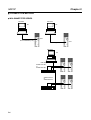
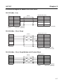
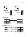
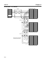
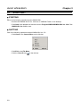
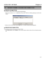
1
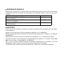
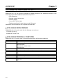
Cat. No. I541-E1-01 USER’S MANUAL OMNUC SMARTSTEP SERIES/ W SERIES WMON Win Ver2.0 MONITORING SOFTWARE for SERVO DRIVER and MOTOR ABOUT THIS MANUAL: This manual describes the specifications and operation of WMON Win Ver.2.0, the monitoring software for servo driver and motor. Please read this manual carefully and understand it thoroughly for correct use. Refer to the user's manual of the applicable servo driver and motor as needed. 1. Intended Audience This manual is intended for the following personnel, who must also have knowledge of electrical systems (an electrical engineer or the equivalent). • Personnel in charge of installing FA systems. • Personnel in charge of designing FA systems. • Personnel in charge of managing FA systems and facilities 2. General Precautions The user must operate the product according to the performance specifications described in the operation manuals. Before using the product under conditions which are not described in the manual or applying the product to nuclear control systems, railroad systems, aviation systems, vehicles, combustion systems, medical equipment, amusement machines, safety equipment, and other systems, machines, and equipment that may have a serious influence on lives and property if used improperly, consult your OMRON representative. This manual provides information that is required for the use of WMON Win Ver. 2.0, the monitoring software for OMNUC SMARTSTEP SERIES/W SERIES. Please read this manual carefully and understand it thoroughly. Also, always keep this manual close at hand for reference. Notice: OMRON products are manufactured for use according to proper procedures by a qualified operator and only for the purposes described in this manual. The following conventions are used to indicate and classify precautions in this manual. Always heed the information provided with them. Failure to heed precautions can result in injury to people or damage to property. !WARNING Indicates a potentially hazardous situation which, if not avoided, could result in death or serious injury. !Caution Indicates a potentially hazardous situation which, if not avoided, may result in minor or moderate injury, or property damage. OMRON Product References All OMRON products are capitalized in this manual. The word “Unit” is also capitalized when it refers to an OMRON product, regardless of whether or not it appears in the proper name of the product. The abbreviation “Ch,” which appears in some displays and on some OMRON products, often means “word” and is abbreviated “Wd” in documentation in this sense. The abbreviation “PLC” means Programmable Controller. The abbreviation “PC,” however, is used in some Programming Device displays to mean Programmable Controller. Visual Aids The following headings appear in the left column of the manual to help you locate different types of information. Note Indicates information of particular interest for efficient and convenient operation of the product. OMRON, 2003 All rights reserved. No part of this publication may be reproduced, stored in a retrieval system, or transmitted, in any form, or by any means, mechanical, electronic, photocopying, recording, or otherwise, without the prior written permission of OMRON. No patent liability is assumed with respect to the use of the information contained herein. Moreover, because OMRON is constantly striving to improve its high-quality products, the information contained in this manual is subject to change without notice. Every precaution has been taken in the preparation of this manual. Nevertheless, OMRON assumes no responsibility for errors or omissions. Neither is any liability assumed for damages resulting from the use of the information contained in this publication. ■ STARTING MULTI-AXIS COMMUNICATIONS !Caution Set a unique unit No. for each Unit. If the same unit No. is set for more than one Unit and communications with a personal computer are started, the driver or personal computer may be damaged. *1 When using multi-axis communications, set the unit No. for each driver before connecting to the personal computer. *2 In multi-axis communications, set the unit No. selecting from 1 to E (14) and F (15). Do not use the unit No. 0. *3 Unit No. setting is not needed for UE. (Multi-axis communications cannot be established.) For SMARTSTEP and UT, set the unit No. using the rotary switch on the front panel. ■ TRANSFERRING PARAMETERS TO DRIVER !Caution ■ Double-check that the assigned unit Nos. are correct before transferring parameters to the driver. Transferring parameters to the driver with incorrect unit Nos. may cause unexpected operation or damage to the equipment. WIRING !Caution Turn OFF the power to both the Servo Driver and personal computer before connecting or disconnecting cables. Not doing so may cause damage to the equipment. !Caution Do not change cable connections while the monitoring software is operating. Otherwise, the equipment may be damaged or malfunction. ■ OPERATION !Caution Always exit the personal computer’s monitoring software before turning ON/OFF the power supply to the Servo Driver. Not doing so may cause damage to the equipment. !Caution Check that people or obstructions are not in the vicinity of the motor or machinery when using the Jogging operation. Also, do not connect or disconnect cables, interrupt the personal computer’s monitoring software operation, or turn OFF the personal computer during operation. Otherwise, the equipment may be damaged. ■ REFERENCE MANUALS Related user’s manuals are as follows. When using Monitoring software, refer to the user’s manuals of applicable products as needed. For information on the manuals, please consult our sales representative. Name OMNUC SMARTSTEP A SERIES Servomotors/Servo Drivers USER’S MANUAL OMNUC SMARTSTEP A SERIES Servomotors/Servo Drivers OPERATION MANUAL OMNUC W SERIES AC SERVOMOTORS/SERVO DRIVERS USER’S MANUAL ■ Cat. No. I533-E1-01 I534-E1-01 I531-E1-03 NOTATION In this manual, the following conventions are used to describe screen messages and mouse/keyboard operations. Names of menus and menu items are indicated in bold italic, e.g., the File Menu. Names of keys and buttons are indicated in bold (usually followed by "Key" or "Button"), e.g., Tab Key and OK Button. Dialog boxes and window names are indicated with capitalization, e.g., the Search Dialog Box. The levels of items in menu hierarchies are distinguished with slashes. For example, "Select File/ New" tells the reader to select New from the File Menu. The "+" sign is used to indicate that keys are pressed simultaneously. For example, "Press the Ctrl+S Keys" tells the reader to press the S Key while holding down the Ctrl Key. "Click/Double-Click" indicates left click/left double-click. "Right Click" is particularly mentioned. Table of Contents Chapter 1. OVERVIEW . . . . . . . . . . . . . . . . . . . . . . . . . . . . . . . . . . . 1-1 1-1 WHAT IS "WMON Win Ver. 2.0"? . . . . . . . . . . . . . . . . . . . . . . . . . . . . . . . . . . . . . . . . . . . . 1-2 FEATURES . . . . . . . . . . . . . . . . . . . . . . . . . . . . . . . . . . . . . . . . . . . . . . . . . . . . . . . . . . . . . . 1-3 DATA CREATED WITH WMON Win Ver. 2.0 . . . . . . . . . . . . . . . . . . . . . . . . . . . . . . . . . . 1-2 1-3 1-5 Chapter 2. SETUP . . . . . . . . . . . . . . . . . . . . . . . . . . . . . . . . . . . . . . . . 2-1 2-1 INSTALLING/UNINSTALLING WMON . . . . . . . . . . . . . . . . . . . . . . . . . . . . . . . . . . . . . . 2-2 CONNECTING WITH PERSONAL COMPUTER . . . . . . . . . . . . . . . . . . . . . . . . . . . . . . . 2-2 2-5 Chapter 3. BASIC OPERATION. . . . . . . . . . . . . . . . . . . . . . . . . . . . 3-1 3-1 START/QUIT . . . . . . . . . . . . . . . . . . . . . . . . . . . . . . . . . . . . . . . . . . . . . . . . . . . . . . . . . . . . . 3-2 Chapter 4. OPERATION METHOD. . . . . . . . . . . . . . . . . . . . . . . . . 4-1 4-1 4-2 4-3 4-4 4-5 4-6 COMMUNICATIONS SETTINGS . . . . . . . . . . . . . . . . . . . . . . . . . . . . . . . . . . . . . . . . . . . . DRIVER CONNECTION AND DISCONNECTION . . . . . . . . . . . . . . . . . . . . . . . . . . . . . . PARAMETER EDIT/SAVE/TRANSFER . . . . . . . . . . . . . . . . . . . . . . . . . . . . . . . . . . . . . . . MONITOR . . . . . . . . . . . . . . . . . . . . . . . . . . . . . . . . . . . . . . . . . . . . . . . . . . . . . . . . . . . . . . . ALARM . . . . . . . . . . . . . . . . . . . . . . . . . . . . . . . . . . . . . . . . . . . . . . . . . . . . . . . . . . . . . . . . . JOGGING/MOTOR ORIGIN SEARCH . . . . . . . . . . . . . . . . . . . . . . . . . . . . . . . . . . . . . . . . 4-2 4-3 4-4 4-9 4-10 4-11 Revision History . . . . . . . . . . . . . . . . . . . . . . . . . . . . . . . . . . . . . . . . . . R-1 1 Chapter 1 OVERVIEW 1-1 1-2 1-3 WHAT IS "WMON Win Ver. 2.0"? FEATURES DATA CREATED WITH WMON Win Ver. 2.0 Chapter 1 OVERVIEW 1-1 WHAT IS "WMON Win Ver. 2.0"? WMON Win Ver. 2.0, the monitoring software for OMNUC SMARTSTEP SERIES/W SERIES, is the computer program that enables the personal computer to: • Edit parameters • Execute system check mode • Perform jogging • Check servo driver status • Display waveforms of speed, torque, and I/O signals Operations mentioned above can be performed with ease. ■ APPLICABLE SERVO DRIVER WMON Win Ver. 2.0 can be used with the following servo drivers: 1.R7D-AP**H/-AP**L 2.R88D-WT**H/-WT**HL ■ APPLICABLE PERSONAL COMPUTER WMON Win Ver. 2.0 can be used on computers that satisfy the following conditions: Item Computer OS CPU Memory Hard disk drive Screen resolution Screen colors CD-ROM drive Communications port 1-2 Requirement IBM PC/AT or equivalent Windows 95 OSR2 or later Windows 98/Me Windows NT 4.0 SP3 or later Windows 2000 Pentium 133 MHz or higher 32 Mbytes min. (64 Mbytes or larger recommended) 50 Mbytes min. (100 Mbytes or larger available memory recommended when installing) SVGA (800 600 pixels) min. 256 colors min. (65536 or more recommended) 1 min. RS232 or RS422 1 port min. OVERVIEW 1-2 ■ Chapter 1 FEATURES EDIT PARAMETER • Parameters edited with the personal computer can be transferred to the servo driver. • Parameters set on the servo driver can be saved to disks (FD, HD, etc.) • Parameters saved in the disc can be read. • Parameters can be changed real-time. Operationality in gain adjustment, etc. has been improved. ■ EXECUTE SYSTEM CHECK MODE • Settings and results of online auto-tuning can be saved. • Analog monitor output and motor current detection offset can be adjusted. • Motor origin search can be performed. • Password can be set. • Speed and torque command offset can be adjusted. (Only with W SERIES) • Absolute encoder can be set up (initialized). (Only with W SERIES) ■ JOGGING • Jogging of the servomotor can be performed. (Jog speed and rotation direction can be specified using the personal computer.) ■ CHECK SERVO DRIVER STATUS • Status (ON/OFF) of the servo driver's I/O signals can be checked. • Internal status of the servo driver can be checked. • Speed feedback, torque command, etc. can be monitored. • Alarms being detected by the servo driver can be checked. ■ DISPLAY SPEED/TORQUE WAVEFORM • Longitudinal data, such as torque command, speed command, speed feedback, position deviation, etc., can be imported and displayed. • Status (ON/OFF) of the I/O signals can be imported as longitudinal data and displayed. • Sampling time can be set as desired in the unit of 250 µs. • Imported data can be saved on the disk. • Waveforms can be output to the printer. ■ MULTI-AXIS COMMUNICATIONS • 1 computer can communicate with up to 15 servo drivers. 1-3 OVERVIEW ■ INITIALIZE PARAMETER • Parameters can be set back to their default settings. ■ INSTALL JAPANESE/ENGLISH • Program software of either Japanese or English version can be installed. 1-4 Chapter 1 Chapter 1 OVERVIEW 1-3 DATA CREATED WITH WMON Win Ver. 2.0 Files created and managed with WMON Win Ver. 2.0 are as follows: Name Parameter file Waveform trace file Extension .usr .ysm Content Parameter files saved with WMON Win Ver. 2.0 Trace files of waveform monitoring saved with WMON Win Ver. 2.0 The following files saved with UMON (monitoring software for MS-DOS) and WMON Win Ver. 1.0 cannot be read, edited, or saved with WMON Win Ver. 2.0. Name Parameter file Waveform trace file Parameter file Extension .ysp .ysm .ual Parameter file .uep Parameter file .uth Content Parameter files saved with WMON Win Ver. 1.0 Trace files of waveform monitoring saved with WMON Win Ver. 1.0 Parameter files for: R88D-UA**HA/-UA**LA/-UA**V/-UA**W R88D-UP**HA/-UP**LA/-UP**V/-UP**W Parameter files for: R88D-UEP**H/-UEP**L/-UEP**V/-UEP**W Parameter files for: R88D-UT**H/-UT**V (1 to 5 kW) To use the parameters for W SERIES saved with WMON Win Ver. 1.0, transfer them to the driver with WMON Win Ver. 1.0 first, and read, edit, and save them with WMON Win Ver. 2.0. Files for U SERIES cannot be used with WMON Win Ver. 2.0. Use them with WMON Win Ver. 1.0 1-5 2 Chapter 2 SETUP 2-1 2-2 INSTALLING/UNINSTALLING WMON CONNECTING WITH PERSONAL COMPUTER SETUP 2-1 ■ Chapter 2 INSTALLING/UNINSTALLING WMON INSTALLING WMON Start WMON Win Install Program to install WMON Win Ver. 2.0. The Install Program has WMON Win Program and Related files. Start installation after quitting all the other running programs. Installation of the program will proceed in the following order. 1.Switch ON the personal computer and start Windows. 2.Insert the CD-ROM into the CD-ROM drive. • Start "Setup.exe" in "WMON Win" Folder on the CD-ROM. • Start Explorer, select and start "Setup.exe" in "WMON Win" on the CD-ROM. The following dialog box will be displayed. 3.Click the English Button for English version. And click the Install Button. (To install Japanese version, click the Japanese Button.) The following dialog box will be displayed. 2-2 SETUP Chapter 2 4.Select "W SERIES". Read the content and click the Next Button. The following dialog box will be displayed. 5.Select a folder in which WMON Win will be installed and click the Next Button. The following dialog box will be displayed. 2-3 SETUP Chapter 2 6.Select a program group that will create icons for WMON Win. The default setting is "WMON Win E". After selecting the group, click the Next Button. Install program will start. The file will be copied from the CD-ROM to the personal computer. Install status will be displayed. Once the installation is completed, the following dialog box will be displayed. 7.Click the Finish Button. ■ UNINSTALLING WMON To remove WMON Win Ver. 2.0 from the personal computer, follow the procedures below: 1.Click Start in the taskbar, and point Setting with the cursor. 2.Click Control Panel. 3.Double-click on "Add/Remove Programs" Icon. 4.Add/Remove Programs Dialog Box will be displayed. Select "WMON Win E" from the list of "Change or Remove Programs" and click the Change/Remove Button. 5.Click the OK Button in the confirmation dialog box. WMON Win Ver. 2.0 will be removed from the personal computer. 2-4 Chapter 2 SETUP 2-2 CONNECTING WITH PERSONAL COMPUTER To transfer parameters created with WMON Win Ver. 2.0 to a servo driver, a personal computer has to be connected to the servo driver with the cables mentioned below, and online communications have to be established. ■ ● CONNECTION FORMAT With SMARTSTEP SERIES SMARTSTEP Servo Driver: R7D-AP PC R7A-CCA002P2 CN3 (TOOL) or CN1 RS-232C or RS-422A ● With W SERIES Servo Driver: R88D-WT PC R88A-CCW002P2 CN3 RS-232C or RS-422A 2-5 Chapter 2 SETUP ■ ● CONNECTION METHOD With SMARTSTEP SERIES RS-232C RS-422A PC PC CN3 R7A-CCA002P2 (2 m) User Original Cable RS-422A PC User Original Cable XW2Z-100J-B7 or XW2Z-200J-B7 XW2B-40J6-4A XW2Z-100J-C1 or XW2Z-200J-C1 XW2B-40J6-4A 2-6 CN1 Chapter 2 SETUP ● Connection diagram for SMARTSTEP Servo Driver RS-232C (Max.: 2 m) PC SMARTSTEP (CN3) SIGNAL PIN Shield PIN SIGNAL RXD 2 1 TXD TXD 3 2 RXD GND 5 8 GND RTS 7 CTS 8 FG Shell Shell FG CONNECTOR: XM2D-0901 (OMRON) HOOD: XM2S-0911 (OMRON) CONNECTOR: HR212-10P-8P (HIROSE) RS-422A (Max.: 30 m): Single PC SIGNAL RXD+ SMARTSTEP (CN1) Shield PIN SIGNAL 22 TXD+ RXD− 23 TXD− TXD+ 20 RXD+ TXD− 21 RXD− 24 RT 19 GND Shell FG GND CONNECTOR: 10136-3000VE (3M) HOOD: 10336-52A0-008 (3M) RS-422A (Max.: 30 m): Single/Multiple with Terminal Block PC SIGNAL RXD+ XW2B-40J6-4A Shield PIN SIGNAL 1 TXD+ RXD− 2 TXD− TXD+ 6 RXD+ TXD− 8 RXD− FG Shell FG CONNECTOR: XM2A-0901 (OMRON) HOOD: XM2S-0911 (OMRON) 2-7 Chapter 2 SETUP RS-422A (Max.: 30 m): Multiple without Terminal Block PC SIGNAL RXD+ SMARTSTEP (CN1) Shield PIN SIGNAL 22 TXD+ RXD− 23 TXD− TXD+ 20 RXD+ TXD− 21 RXD− 24 RT 19 GND Shell FG GND Shield PIN SIGNAL 22 TXD+ 23 TXD− 20 RXD+ 21 RXD− 24 RT 19 GND Shell FG Shield PIN Short-circuit RT and RXD− on the last Servo Driver. SIGNAL 22 TXD+ 23 TXD− 20 RXD+ 21 RXD− 24 RT 19 GND Shell FG Last Servo Driver 2-8 Chapter 2 SETUP ● With W SERIES RS-232C RS-422A PC PC CN3 R88A-CCW002P2 (2 m) ● CN3 User Original Cable Connection diagram for W SERIES Servo Driver RS-232C (Max.: 2 m) PC W Series Servo Driver SIGNAL PIN Shield PIN SIGNAL RXD 2 2 TXD− TXD 3 4 RXD− GND 5 14 GND RTS 7 CTS 8 FG Shell Shell FG Connector: XM2D-0901 (OMRON) Hood: XM2S-0911 (OMRON) Connector: 10114-3000VE (3M) Hood: 10314-52A0-008 (3M) RS-422A (Max.: 30 m): Single PC SIGNAL RXD+ W Series Servo Driver Shield PIN SIGNAL 1 TXD+ RXD− 2 TXD− TXD+ 3 RXD+ TXD− 4 RXD− 6 RXD− 7 RT 14 GND Shell FG GND 2-9 Chapter 2 SETUP RS-422A (Max.: 30 m): Multiple PC SIGNAL RXD+ W Series Servo Driver Shield PIN SIGNAL 1 TXD+ RXD− 2 TXD− TXD+ 3 RXD+ TXD− 4 RXD− 6 RXD− 7 RT 14 GND Shell FG GND Shield PIN SIGNAL 1 TXD+ 2 TXD− 3 RXD+ 4 RXD− 6 RXD− 7 RT 14 GND Shell FG Shield PIN Short-circuit RT and RXD− on the last Servo Driver. SIGNAL 1 TXD+ 2 TXD− 3 RXD+ 4 RXD− 6 RXD− 7 RT 14 GND Shell FG Last Servo Driver 2-10 3 Chapter 3 BASIC OPERATION 3-1 START/QUIT Chapter 3 BASIC OPERATION 3-1 ■ START/QUIT STARTING Either of the following operations starts WMON Win. • Double-click WMON Win E Ver. 2.00 Icon in OMRON Folder on the desktop. • Click Start in the taskbar and move the cursor Program/OMRON/WMON Win Ver. 2.00. Click WMON Win Ver. 2.00 to start. ■ QUITTING One of the following operations closes WMON Win Ver. 2.0. • Click Close in the Control Menu on the title bar. • Click Exit in the File Menu. • Click the Close Button 3-2 in the title bar. 4 Chapter 4 OPERATION METHOD 4-1 4-2 4-3 4-4 4-5 4-6 COMMUNICATIONS SETTINGS DRIVER CONNECTION AND DISCONNECTION PARAMETER EDIT/SAVE/TRANSFER MONITOR ALARM JOGGING/MOTOR ORIGIN SEARCH OPERATION METHOD 4-1 ■ Chapter 4 COMMUNICATIONS SETTINGS COMMUNICATIONS SETTINGS Communications settings will proceed as follows: 1.Click Connect in the File Menu. The Connect Dialog Box will be displayed as shown below. 2.Select Online. Select a port for communication with the Servo Driver in the Port Box. Select a medium to be used for communications in the Media Box. Set the same unit No. set on the connected Servo Driver in the Axis Address Box. ■ COMMUNICATIONS WITH MULTIPLE SERVO DRIVERS When RS422A cable is used, WMON Win can establish communications with multiple Servo Drivers. To establish communications among multiple Servo Drivers, follow the procedures below. 1.Connect the personal computer to the Servo Driver with RS422A cable. 2.Click Connect in the File Menu to display Connect Dialog Box. 3.Select RS422 in the Media Box. 4.Set the last unit No. of the connected Servo Drivers. 5.Follow the procedures in 4-2 DRIVER CONNECTION AND DISCONNECTION to connect to the Servo Driver. Connection to another Servo Driver cannot be made during the setting for a Servo driver. Once the operation of the connected Servo Driver is completed, click Connect in the File Menu to make connection to another Servo Driver, following the procedures in 4-2 DRIVER CONNECTION AND DISCONNECTION. 4-2 OPERATION METHOD 4-2 ■ Chapter 4 DRIVER CONNECTION AND DISCONNECTION DRIVER CONNECTION To connect to a Servo Driver, follow the procedures below. 1.After the procedures in 4-1 COMMUNICATIONS SETTINGS, the following dialog box will be displayed. 2.Select a Servo Driver and click the OK Button. The basic window will be displayed. ■ DRIVER DISCONNECTION The following operation disconnects a Servo Driver. 1.Click Disconnect in the File Menu. The communications with the Servo Driver will be disconnected. 4-3 Chapter 4 OPERATION METHOD 4-3 ■ PARAMETER EDIT/SAVE/TRANSFER EDIT PARAMETERS Follow the procedures below to edit parameters. 1.Click Parameters/Edit Parameters. The following window will be displayed. ● Parameter edit window Drag to change the display width. Change the parameter editing level. Print. Save as file. Edit the settings. Add comments. Select all parameters. Import file. Write parameters. Initialize parameters. Read parameters. Compare parameters. The contents of the window above are as follows: Item No. Name Value Unit Min Max Default 4-4 Content Indicates parameter Nos. By marking the box on the left, the marked parameters will be initialized, compared, read, or written. Additionally, parameters for which the setting values are changed will be marked. Indicates the names of parameters. Indicates the current setting values of parameters. Change the values in this column when editing the parameters. The color of the column will change when the parameter setting value read from a Servo Driver or a parameter file is changed. Indicates the setting units for parameters. Indicates the minimum value that can be set for each parameter. Setting a smaller value than the minimum value will cause a setting error. Indicates the maximum value that can be set for each parameter. Setting a larger value than the maximum value will cause a setting error. Indicates the factory default value for each parameter. Clicking the Initialize Button will change the current setting values of the marked parameters to the default values. OPERATION METHOD Chapter 4 Edit parameters through the following operations. ● Parameter setting method Change setting values through either of the following operations. • Click on the parameter to be edited and click the Edit Button. • Double-click on the parameter to be edited. The Edit Window will be displayed. Change the settings as needed and click the OK Button. ■ SAVE PARAMETERS Save parameters through the following operations. 1.Click the File Save Icon at the upper left corner. The Save As Window will be displayed. 2.Enter a file name and click the Save Button. ■ ● TRANSFER PARAMETERS Sending all parameters being edited to a Servo Driver 1.Click the Select All Check Box. 2.Click the Write Button and all the parameters will be sent to a Servo Driver. ● Sending selected parameters to a Servo Driver 1.Click the check boxes in the No. column for the parameters to be sent. 2.Click the Write Button and the selected parameters will be sent to a Servo Driver. ● Receiving all parameters from a Servo Driver 1.Click the Select All Check Box. 2.Click the Read Button and all the parameters will be received from a Servo Driver. ● Receiving selected parameters from a Servo Driver 1.Click the check boxes in the No. column for the parameters to be received. 2.Click the Read Button and the selected parameters will be received from a Servo Driver. ■ COMPARE PARAMETERS Parameters being edited are compared with the ones in a Servo Driver. 1.Click the Compare Button. The Compare Confirmation Dialog Box will be displayed. 2.Click the OK Button. The comparison will be executed and the result will be displayed. 3.The parameters with differences will be listed up. At this point, the comparison result can be saved. To save the result, click the Save Icon in the Comparison Results Window. After entering a file name, click the Save Button. 4-5 OPERATION METHOD ■ Chapter 4 INITIALIZE PARAMETERS Parameters in a Servo Driver are initialized. 1.Click the Initialize Button. The Verification Dialog Box will be displayed. 2.Click the OK Button and the initialization will be executed. ■ READ PARAMETERS Saved parameter file is read. 1.Click the Import Button. The Open Dialog Box will be displayed. 2.Enter a file name to be read and click the OK Button. The file will be imported. ■ ENTER COMMENTS Comments can be entered to record setting history, etc. By saving parameters, comments are also saved. 1.Click the Comment Button. The Comment Window will be displayed. 2.Enter comments and click the OK Button. ■ EDIT PARAMETERS ONLINE Parameters can be edited online. For gain adjustment, etc., this function comes handy when parameters are to be changed real-time. 1.Click Parameters/Edit Online Parameters. 2.Click the Setup Button. The Set Parameters Dialog Box will be displayed. Click the Set Button to display the parameter list. Select a parameter and click the OK Button. 4-6 OPERATION METHOD Chapter 4 3.Click the OK Button to bring back the Set Parameters Dialog Box with the selected parameter on it. Click the OK Button and the following window will be displayed. 4.Change the parameter using the digital switches in the window. ● Creating a new parameter file offline 1.Click Parameters/Edit Parameters. The following dialog box will be displayed. 2.Select "Load from File" to edit a saved file. Select "Select New Servo Driver" to create a new file. After the selection is made, click the OK Button. 3.When "Load from File" is selected, the Open Dialog Box will be displayed. Select a file name and click the OK Button to display the Parameter Edit Window. 4.When "Select New Servo Driver" is selected, the Servo Driver Selection Dialog Box will be displayed. 4-7 OPERATION METHOD Chapter 4 Select a Servo Driver whose parameters are to be edited and click the Next Button. The following dialog box will be displayed. 5.Enter the software version of the Servo Driver, select a Servo Driver Capacity, and click the Done Button. The Parameter Editing Window will be displayed. Follow the procedures described in EDIT PARAMETERS of 4-3 PARAMETER EDIT/SAVE/TRANSFER. 4-8 Chapter 4 OPERATION METHOD 4-4 MONITOR Operation and I/O status of the Servo Driver and Servomotor can be monitored. Follow the procedures below. 1.Connect to a Servo Driver following the procedures described in 4-2 DRIVER CONNECTION AND DISCONNECTION. 2.Click Monitor/Monitor and select an item to be monitored. Check column Monitor data 3.Click on the check box for each monitored item. The monitor data will be displayed in the Value Column. 4-9 OPERATION METHOD 4-5 Chapter 4 ALARM Alarm status of the Servo Driver and Servomotor can be monitored. Additionally, alarms can be reset, alarm history can be monitored, and alarm history can be cleared. See the Alarm Display Window below. 4-10 OPERATION METHOD 4-6 Chapter 4 JOGGING/MOTOR ORIGIN SEARCH Through WMON Win operation, Jogging and Motor Origin Search can be executed. During Jogging or Motor Origin Search, input of the control input signal (CN1) is disabled. Perform either without any load on the motor. !Caution Check that people or obstructions are not in the vicinity of the motor or machinery when using the Jogging operation. Also, do not connect or disconnect cables, interrupt the personal computer’s monitoring software operation, or turn OFF the personal computer during operation. Otherwise, the equipment may be damaged. Follow the procedures below to perform Jogging. 1.Turn OFF the RUN Command Input (RUN) of the Control Inputs (CN1) on the Servo Driver. 2.Connect to the Servo Driver following the procedures described in 4-2 DRIVER CONNECTION AND DISCONNECTION. 3.Click Test Run/Jog. Jog Operation Warning Dialog Box will be displayed. Read and understand the content and click the OK Button. The following window will be displayed. 4.Click the Edit Button and set the Jog Speed. (The value set here will be reflected in the parameter (Jog Speed) on the Servo Driver.) 5.Clicking the Servo ON Button will start power distribution to the Servomotor. 6.Rotate the Servomotor using the Forward and Reverse Buttons. 7.Click Servo OFF to finish Jog Operation. To perform Motor Origin Search, click System Check Mode/Search Motor Origin. Follow the procedure through 5 to 7 for Jog Operation. 4-11 Revision History A manual revision code appears as a suffix to the catalog number on the front cover of the manual. Cat. No. I541-E1-01 Revision code The following table outlines the changes made to the manual during each revision. Page numbers refer to the previous version. Revision code Date 01 December 2003 Revised content Original production R-1