1
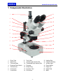
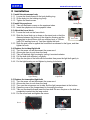
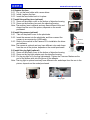
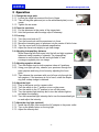
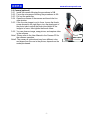
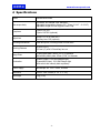
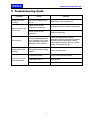
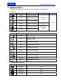
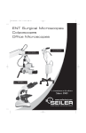
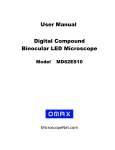
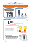
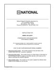
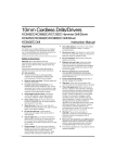
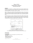
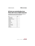
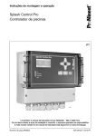
User Manual
Trinocular Stereo Microscope
V434
Model XV434 Series
MicroscopeNet.com
Table of Contents
i. Caution……..……………………………………………………………1
ii. Care and Maintenance……….………………………………….….…2
1. Component Illustration………………………….…………………..…3
2. Installation………………………………………………………………4
3. Operation ….…………………………………………………………...6
4. Specifications…………………….………………………………….....8
5. Troubleshooting Guide....................................................................9
6. Optional Parts…………………………………………………………10
www.microscopenet.com
i. Caution
1. Find the “UP” sign and place the Styrofoam container on your table or bench so
that the arrow is pointing upward. Open the shipping carton carefully to prevent
any accessory, like eyepieces, from dropping and being damaged.
2. Do not discard the molded Styrofoam container. The container should be retained
should the microscope ever requires reshipment.
3. Keep the instrument out of direct sunlight, high temperature or humidity, and dusty
environments. Ensure that the microscope is located on a smooth, level and firm
surface.
4. If any specimen solutions or other liquids splash onto the stage, objective or any
other component, disconnect the power cord immediately and wipe up the spillage.
Otherwise, the instrument may be damaged.
5. Important: the lamp, lamp housing and adjacent parts will become very hot. Do
not touch these parts until they have completely cooled. Never attempt to handle a
hot halogen bulb.
6. All electrical connectors (power cord) should be inserted into an electrical surge
suppressor to prevent damage due to voltage fluctuations.
7. For safety when replacing the halogen lamp or fuse, be sure the main switch is off,
unplug the power cord, and only replace the halogen bulb after the bulb and the
lamp house has completely cooled.
8. Confirm that the input voltage indicated on your microscope corresponds to your
line voltage. The use of a different input voltage other than that as indicated will
cause severe damage to the microscope.
-1-
www.microscopenet.com
ii. Care and Maintenance
1. Do not attempt to disassemble any component including eyepieces, objectives or
focusing mechanism.
2. Keep the instrument clean; remove dirt and debris regularly. Accumulated dirt on
metal surfaces should be cleaned with a damp cloth. More persistent dirt should be
removed using a mild soap solution. Do not use organic solvents for cleansing.
3. The outer surface of the optics should be inspected and cleaned periodically using
an air stream from an air bulb. If dirt remains on the optical surface, use a soft cloth
or cotton swab dampened with a lens cleaning solution (available at camera
stores). All optical lenses should be swabbed using a circular motion. A small
amount of absorbent cotton wound on the end of a tapered stick makes a useful
tool for cleaning recessed optical surfaces. Avoid using an excessive amount of
solvents as this may cause problems with optical coatings or cemented optics or
the flowing solvent may pick up grease making cleaning more difficult.
4. Store the instrument in a cool, dry environment. Cover the microscope with the
dust cover when not in use.
-2-
www.microscopenet.com
1 Components Illustration
1
11
2
12
3
13
4
14
5
15
6
16
7
17
8
18
9
19
10
20
21
1
2
3
4
5
6
7
Photo Tube
Stand Post
Trinocular Body
Eyepiece/Photo Switch
Thumb Screw
Focus Knob
Focus Block
8
9
10
11
12
13
14
Post Collar
Incident Light Intensity Dial
Transmitted Light Intensity Dial
Eyepiece
Diopter Ring
Eyepiece Tube
Zoom Knob
-3-
15
16
17
18
19
20
21
Holding Ring
Objective Housing
Incident Light
Power Switch
Stage Clip
Stage Plate
Base
www.microscopenet.com
2 Installation
2.1 Install the microscope body
2.1.1 Loosen the thumb screw on the body holding ring.
2.1.2 Sit the body into the holding ring firmly.
2.1.3 Tighten the thumb screw.
Thumb Screw
Holding Ring
2.2 Install the eyepieces
2.2.1 Take off the plastic covers on the eyepiece tubes.
2.2.2 Insert the eyepieces into the eyepiece tubes.
2.3 Adjust the focus block
2.3.1 Loosen the knob on the focus block.
2.3.2 Slide the focus block up or down on the stand post so that the
distance between the bottom of the objective housing and the
Post Collar
stage plate is about 95mm (with no auxiliary lens) or 150mm
(with 0.5X auxiliary lens on). And then tighten the knob.
2.3.3 Slide the post collar to against the focus block as showed in the figure, and then
tighten its knob.
2.4 Replace the incident light bulb
2.4.1 Turn the power off and disconnect the power cord.
2.4.2 Allow some time to cool down the lamp.
2.4.3 Take off the black light housing by turning it counterclockwise.
2.4.4 Pull the bulb (with reflector) out gently.
2.4.5 Align the two pins of the bulb with the sockets then press the light bulb gently in.
2.4.6 Put the light housing on and tighten by turning it clockwise.
Light Bulb
Light Housing
2.5 Replace the transmitted light bulb
2.5.1 Turn the power off and disconnect the power cord.
2.5.2 Allow some time to cool down the lamp.
2.5.3 Turn over the microscope on its side; find the light compartment at the bottom.
2.5.4 Open the cover of the compartment by loosening the screw.
2.5.5 Take out the dead bulb and insert the new bulb. Be sure the pins on the bulb are
completely inserted into the lamp socket.
2.5.6 Put the cover back and tighten the screw.
Screw
Light Bulb
Light Compartment
-4-
www.microscopenet.com
2.6 Replace the fuse
2.6.1 Pry out the fuse holder with a screw driver.
2.6.2 Install / replace the fuse.
2.6.3 Insert the fuse holder back to its place.
Fuse Holder
2.7 Install the auxiliary lens (optional)
2.7.1 Screw off the plastic cover on the bottom of objective housing.
2.7.2 Screw on the auxiliary lens onto the objective housing.
Note: The auxiliary lens is optional and may have different color and
shape from the one in the picture, depends on the model
purchased.
2.8 Install the camera (optional)
2.8.1 Take off the plastic cover on the phototube.
2.8.2 Insert the camera into the phototube, and then connect the
camera to a computer by a USB cable.
2.8.3 Refer to the manual in the Camera CD to installation the driver
and software.
Note: The camera is optional and may have different color and shape
from the one in the picture, depends on the model purchased.
Auxiliary Lens
Camera
Photo Tube
2.9 Install the ring light (optional)
2.9.1 Screw off the plastic cover on the bottom of objective housing.
2.9.2 Screw on the ring light adapter onto the objective housing.
2.9.3 Put the ring light on to the ring light adapter. Tighten the 3 screws. Make sure the
end of the screws stick into the groove of the adapter.
Note: The ring light is optional and may have different color and shape from the one in the
picture, depends on the model purchased.
Ring Light
Ring Light Adapter
-5-
www.microscopenet.com
3 Operation
3.1 Change the stage plate
3.1.1 Loosen the stage lock screw at the front of base.
3.1.2 Take off the glass plate and put on the white/black plate (or vice
versa).
3.1.3 Tighten the set screw.
Thumb Screw
3.2 Place the specimen
3.2.1 Put the specimen in the center of the stage plate.
3.2.2 Hold the specimen with the stage clips if necessary.
3.3 Focusing
3.3.1 Turn the zoom knob at 0.7.
3.3.2 Turn the focus knob until the specimen is in focus.
3.3.3 Move the interesting spot of specimen into the center of field of view.
3.3.4 Turn the zoom knob for the desired magnification.
3.3.5 Adjust the focus knob slightly to get clear image.
3.4 Adjusting interpupillary distance
While observing with both eyes, hold the left and right eyepiece
tubes and swing inwards or outwards. The interpupillary
distance is correct when the left and right fields of view
converge completely into one image.
3.5 Adjusting eyepiece diopter
3.5.1 Turn the diopter rings on both eyepiece tubes at 0 positions.
3.5.2 Using your right eye only, observe your specimen through the
right eyepiece and bring it into focus by adjusting the focus
knob.
3.5.3 Then observe the specimen with your left eye only through the
left eyepiece. If the specimen is not in focus, rotate the diopter
ring until a sharp image is obtained.
3.6 Adjust the light
3.6.1 Plug in the power cord to a power outlet.
3.6.2 Turn the switch to the “I” position to turn on the power.
3.6.3 Turn the switch to the “O” position to turn off the power.
3.6.4 Turn the incident light intensity dial to turn the incident light on
and adjust the intensity.
3.6.5 Turn the transmitted light intensity dial to turn the transmitted light
on and adjust the intensity.
3.7 Adjust the ring light (optional)
3.7.1 Install the ring light, and connect the AC adapter to the power outlet.
3.7.2 Turn on the power button on the ring light.
3.7.3 Adjust the intensity dial.
-6-
Power Switch
www.microscopenet.com
3.8 Camera (optional)
3.8.1 Install the camera following the procedures in 2.8.
3.8.2 Focus the microscope following the procedures in 3.3.
3.8.3 Pull out the switch bar.
3.8.4 Open the software of the camera and launch the live
view window.
3.8.5 If the live view image is not in focus, loosen the thumb
screw showed in the right figure, turn the plastic part of
the photo tube to adjust the photo tube height till the
image is in focus, then tighten the thumb screw.
3.8.6 You can observe image, snap picture, and capture video
in the software.
Note1: Please refer to the User Manual in the Camera CD for
the software operation.
Note2: The camera is optional and may have different color
and shape from the one in the picture, depends on the
model purchased.
-7-
Plastic Part
Thumb
Switch Bar
www.microscopenet.com
4 Specifications
Model
V434/XV434 Series
Microscope body
Trinocular, 45º inclined, 360º swiveling.
Adjustable Interpupillary distance 55 ~ 75mm (2-3/16” ~ 2-15/16”)
Adjustable diopter on both eyepiece tube ±5dp
Eyepieces
1 pair of WF10X
1 pair of WF20X (optional)
Objectives
Zoom 0.7x ~ 4.5x, ratio 6.5:1
Auxiliary lens 0.5X (optional)
Focusing Mechanism
Rack and pinion, focusing knobs on both sides
Working Distance
95 mm (3-3/4”)
152 mm (6”) with 0.5X auxiliary lens on
Stage Plate
Frosted glass plate: 95mm (3-3/4”) in diameter
White/black plastic plate: 95mm (3-3/4”) in diameter
Illumination
Incident (upper): 12V/10W halogen light
Transmitted (lower): 12V/10W halogen light
With switch and intensity dials separately
Power Supply
Microscope: AC 110V – 240V, 50/60Hz
Dimension
23cm x 16cm x 44cm (9” x 6” x 17-1/2”)
Net weight
6 kg (13 lb)
-8-
www.microscopenet.com
5 Troubleshooting Guide
Symptom
Totally dark in the
view field
Cause
Remedy
The cover of objectives is
still on
Take off the cover of objectives
Stains or dust on the
eyepieces or objectives
Clean the lens with a camera cleaning kit
Stains or dust on the
specimen
Clean the specimen
Can not focus
The focus block/objectives
is too far away or too close
to the specimen and out of
the range of focus stroke
Adjust the height of the focusing
mechanism so that the distance between
the objectives and specimen is about
95mm (with no auxiliary lens) or 152mm
(with 0.5X auxiliary lens on).
Image moves while
focusing
Specimen rises from stage
surface
Secure the specimen
No electrical power
Check power cord connection
Lamp bulb burnt out
Replace bulb
Fuse blown out
Replace fuse
Stains or dust on the
field of view
Lamp does not light
when switched on
-9-
www.microscopenet.com
6 Optional Parts
(The optional parts may be included in some models or sold separately.)
6.1.1 Camera
Model
Resolution
A1502
640 x 480 (0.3MP)
A1510
1280 x 1024 (1.3MP)
A1520C
1600 x 1200 (2.0MP)
A1530
2048 x 1536 (3.0MP)
A1550
2592 x 1944 (5.0MP)
A1590
3488 x 2616 (9.0MP)
Operating System
Software
MS Windows
(32/64bit)
Included
MS Windows
(32bit)
MS Windows
(32/64bit)
6.1.2 Illuminator
Model
Lamp
A12CR
Halogen 21V/150W
Fiber Cold Ring Light
A12CY
Halogen 21V/150W
Fiber Cold Y Light
A9208
8W Fluorescent Ring Light
A9212
128W Fluorescent Ring Light
A9239
39 LEDs Macro Ring Light
A9254
A9254P
54 LEDs Macro Ring Light
A9264S
64 LEDs Macro Ring Light
A92144B
144 LEDs Macro Ring Light
A92144L
144 LEDs Macro Ring Light
A92144S
144 LEDs Macro Ring Light
6.1.3 Auxiliary Objective Lens
Model
Magnification
AJ5D3AUX
0.3X
AJ5D5AUX
0.5X
AJ5D75AUX
0.75X
AJ5X2
0.2X
- 10 -