1
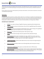
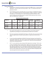
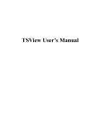
Richter Optica
[email protected]
Instructions for Models:
HS-1M, HS1+1, HS-1D
Compound Microscope
Dual Observer
Eyepiece
Diopter Adjustment
Arm
Safety rack stop
Nosepiece
Objective Lenses
Stage Clips
Stage
Disc Diaphragm
Coarse-focusing
Knob
Lamp House
Fine-focusing
knob
Rheostat Control
Base
DUAL HEAD MODELS (HS-1+1, HS-1D Models)
Iris Diaphragm
MONOCULAR MODEL (HS-1M)
Thank you for your purchase of a Richter Optica microscope. The information in this manual is provided to answer most
questions that can arise when operating your microscope and to help you avoid unnecessary maintenance expenses in
the future.
Please carefully read instructions before operating microscope. Nomenclature used to describe components and controls
are identified on opposite page.
UNPACKING
Do not discard styrofoam container or packing materials until you are sure shipment is complete and undamaged (retain
stryrofoam shipping container to store your microscope when it is not in use). Remove all tape and packing material used
to protect microscope during shipment. Make certain lens surfaces do not come in contact with dirt, fingerprints or oil.
Damage of lens surfaces occur when they come in contact with such contaminants, and image clarity is reduced.
DESCRIPTION OF COMPONENTS
1
A.
EYEPIECE: Lens closest to the eye. Magnifies the primary image formed by the objective lens.
B.
OBJECTIVE LENS: Lens closest to the specimen, forms the first magnified image of the specimen.
C.
NOSEPIECE: Revolving turret designed to hold objective lenses, permits changes of magnification
by rotating different powered objective lenses into the optical path.
D.
STAGE CLIPS: Two locked on clips hold specimen slide in place on stage.
E.
STAGE: Platform of the microscope where the specimen slide is placed on the stage.
F.
DISC DIAPHRAGM: Rotating disc located below the stage, with 6 holes of various apertures,
designed to help achieve optimum resolution of the objective lens. Smaller apertures used for
lower magnifications, and larger apertures used for higher magnifications.
G.
COARSE-FOCUS KNOB: Located on each side of the arm, raises or lowers the stage to bring the
specimen tage into focus.
H.
FINE-FOCUS KNOB: (located just below coarse focusing knobs) permit more precise image
adjustment.
I.
LAMP HOUSE ILLUMINATION: Microscope is provided with a built-in LED illuminator.
J.
SAFETY RACK STOP: When properly adjusted, controls maximum upward travel of stage. Prevents
higher power objectives from breaking slides, prevents damage to objective lenses. This stop has
been pre-adjusted at the factory and will not need any further adjustment
1.
Changing Magnification
a.
Magnification is changed by rotating the nosepiece until a different lens is moved into the
optical path. Always turn the turret until you hear it “click”. This indicates that the lens is
properly positioned.
b.
The standard lenses that are provided with your microscope are a widefield 10x eyepiece
(HS1+1, HS-1D Models come with 2 separate eyetubes as well as 2 eyepieces). 4x, 10x and
40x objectives. The 40x objective has a special spring retractable mechanism which
retracts slightly when front of lens comes in contact with the specimen slide. See chart
below for specifications on objectives:
OBJECTIVE SPECIFICATION CHART
Objective
N.A.
Color Code
Ring
Din 4x
0.10
Red
Din 10x
0.25
Din 40x
0.65
retractable
Working
Distance
Mag with
WF10x Eyepiece
4.5mm
18.5mm
40x
Yellow
1.8mm
6.4mm
100x
Blue
0.45mm
0.5mm
400x
Field of View
c.
Also note that each objective has a color ring. This allows you to quickly change in
magnification by referring to an easily observed color rather than to a number.
d.
The microscope has been parfocalled at the factory, which allows the user to easily change
from one magnification to another requiring little or no adjustment of the fine focus
knobs.
e.
As you increase the magnification, the field of view (area of specimen seen through the
microscope) will decrease. That is why it is easier to find the specific area of interest on the
specimen by starting with the lowest 4x objective lens , before increasing magnification
with the 10x or 40x objective lens.
f.
NOTE: Care must be taken when rotating the 40x objective lens into place. This lens has
a spring retractable mechanism which retracts slightly into its housing if the front of the
lens strikes the specimen slide. With fine focus adjustment at mid-range, the rack stop has
been adjusted at the factory to assure the 40x lens will clear the thickness of a normal
specimen slide and cover slip. However, if the rack stop has been improperly adjusted, or
if you are using a thicker than 0.17mm cover slip, moving the 40x lens too quickly could
cause damage to the front lens element or to the slide.
2
g.
2.
Do not let the lens element come into contact with a wet slide surface, as prolonged
contact with any moisture could damage the lens. If lens is exposed to moisture, promptly
wipe with lens paper/microfiber cloth to remove moisture.
Diopter adjustment for HS1+1 dual head model.
These dual head models have a 30 degree inclined eyepiece to provide comfortable viewing for
the primary viewer. They also have a vertical eyepiece so that a second viewer can observe the
image simultaneously. The primary viewer will have focused the microscope using the coarse and
fine focus knobs. To compensate for differences in vision between primary and second viewer,
second viewer may have to adjust image in vertical eyepiece by turning the knurled diopter
adjustment.
3.
Camera adaptation for model HS1-D
The video camera will be mounted on the vertical eyepiece tube, using the adapter you were
provided with. You will need to pull out the eyepiece from the vertical tube and insert the
adapter into the tube with the threads facing upwards. Then screw the camera into the threads
to attach to the microscope.
Note that when using a camera with the microscope, focusing of the image is accomplished by
turning the microscope focusing knobs while observing the image on the display screen. Under
these circumstances, the image observed through the inclined eyepiece will not be in focus.
MAINTENANCE
WARNING: For your own safety, turn switch off and remove plug from power source before
maintaining your microscope. If the power cord is worn, cut or damaged in any way, have it
replaced immediately to avoid shock or fire hazard.
1.
Optical Maintenance
Do not attempt to disassemble any lens components. Consult a microscope service technician
when any repairs not covered by instructions are needed.
Prior to cleaning any lens surface, brush dust or dirt off lens surfaces using a camel hair brush, or
use air to blow dust and lint off of the surfaces. Use of compressed air from a can is an ideal
source of clean air.
3
Do not remove eyepieces or objective lenses to clean. Clean only the outer lens surface. Breathe on lens
to dampen surface, then wipe with lens paper or use a cotton swab moistened with distilled water.
Wipe lens with a circular motion, applying as little pressure as possible. Avoid wiping dry lens surface as
lenses are scratched easily. If excessive grease or dirt gets on the lens surfaces, a small amount of windex
or distilled water can be used on a cotton swab or lens tissue. To clean objective lenses, clean front lens
element only, following the same procedure.
NOTE: Fingerprints or other matter on the front lens element of the objective lens is the single most
common reason that you will experience difficulty in focusing the microscope. Before
having costly servicing done, or before returning for warranty repair, we ask that you first make
certain to examine the front lens element with a magnifying glass or eye loupe for the presence
of such contaminants. If a microscope is returned for warranty repair, and it is determined that such
contaminants are the problem, this is not covered under warranty and we will submit a cost estimate for
cleaning.
2.
Mechanical Maintenance
a.
The rack stop screw has been pre-adjusted at the factory and should not require
re-adjustment. However if you do attempt re-adjustment, note the following procedure:
Loosen round knurled locking nut by turning counter-clockwise. Then loosen stop screw. With the
fine focus adjustment at mid-range, focus on standard slide until sharp image is achieved. Rotate
rack stop screw in clockwise direction until tight. Lock into position with the locking nut. A needle
nose pliers might be needed to loosen the round locking nut.
b.
3.
Metal Parts: Use a clean, damp cloth to remove dust or dirt from metal parts, followed by
a dry cloth.
Electrical Maintenance
a.
To replace the rechargable batteries, you will need to lay the microscope on its arm with
the bottom facing towards you.
b.
Unscrew the 4 screws holding the rubber feet in place and set aside.
c.
Once screws are removed, you will also need to remove the metal plate and set aside.
d.
Next, you will need to remove the 2 silver screws holding the black battery box in place. There is
also a gold washer under each that you will need to remove and set aside.
e.
Once removed, there is a smaller black screw on the opposite side of the battery box that will need
to be removed and set aside.
f.
Once all screws have been removed, with your thumb pressed down on the 4 black lines of the
battery box, push up until the back of the box comes off to expose the batteries.
g.
Once batteries are replaced, make sure all screws are properly tightened before operation.
4
TROUBLESHOOTING
Problem
Reason for Problem
Solution
Outlet inoperative.
Have qualified service technician
repair outlet.
AC Power cord not connected.
Plug into outlet.
Bulb burned out, Fuse blown
Have qualified service technician
replace bulb and/or fuse
Light Fails to operate.
Problem
Image does not remain in
focus
Image will not focus
Poor Resolution
(Image not sharp)
Spots in field of view
Reason for Problem
Solution
Outlet inoperative.
Have qualified service technician
repair outlet.
AC Power cord not connected.
Plug into outlet.
Bulb burned out, Fuse blown
Have qualified service technician
replace bulb and/or fuse
Rack stop not set at proper position
Adjust rack stop
Slide upside down
Place slide on stage with cover slip up
Slide cover slip too thick
Use 0.17 mm thick cover slip
(No. 1cover slip)
Objective lenses dirty
Clean objective lenses
Eyepiece lens dirty
Clean eyepiece lenses
Too much light
Adjust disc diaphragm
Eyepiece or condenser lens too dirty
Clean lens
Specimen slide dirty
Clean slide
***Spots in field of view can also result from dirt on inside of eyepiece. It is recommended that you have a
service technician clean inside of lens.
5