1
AdeptVision
User’s Guide
Version 13.0
AdeptVision
User’s Guide
Version 13.0
Part Number 00963-03300 Rev. A
July 1998
150 Rose Orchard Way • San Jose, CA 95134 • USA • Phone (408) 432-0888 • Fax (408) 432-8707
Otto-Hahn-Strasse 23 • 44227 Dortmund • Germany • Phone (49) 231.75.89.40 • Fax(49) 231.75.89.450
41, rue du Saule Trapu • 91300 • Massy • France • Phone (33) 1.69.19.16.16 • Fax (33) 1.69.32.04.62
The information contained herein is the property of Adept Technology, Inc., and shall not be reproduced in whole or in part without prior written approval of Adept Technology, Inc. The information herein is subject to change without notice and should not be construed as a
commitment by Adept Technology, Inc. This manual is periodically reviewed and revised.
Adept Technology, Inc., assumes no responsibility for any errors or omissions in this document.
Critical evaluation of this manual by the user is welcomed. Your comments assist us in preparation of future documentation. A form is provided at the back of the book for submitting your
comments.
Copyright 1992–1998 by Adept Technology, Inc. All rights reserved.
The Adept logo is a registered trademark of Adept Technology, Inc.
Adept, AdeptOne, AdeptOne-MV, AdeptThree, AdeptThree-XL, AdeptThree-MV, PackOne, PackOneMV, HyperDrive, Adept 550, Adept 550 CleanRoom, Adept 1850, Adept 1850XP,
A-Series, S-Series, Adept MC, Adept CC, Adept IC, Adept OC, Adept MV,
AdeptVision, AIM, VisionWare, AdeptMotion, MotionWare, PalletWare, FlexFeedWare,
AdeptNet, AdeptFTP, AdeptNFS, AdeptTCP/IP, AdeptForce, AdeptModules, AdeptWindows,
AdeptWindows PC, AdeptWindows DDE, AdeptWindows Offline Editor,
and V+ are trademarks of Adept Technology, Inc.
Any trademarks from other companies used in this publication
are the property of those respective companies.
Printed in the United States of America
Table of Contents
Introduction
. . . . . . . . . . . . . . . . . . . .
Compatibility . . . . . . . . . . . . . . . . . . . . . . .
What’s New in AdeptVision VXL Version 13.0 . . . . . . . . . .
ObjectFinder Changes . . . . . . . . . . . . . . . .
Feature-based Refinement . . . . . . . . . . . . .
Improved Handling of Complex Parts . . . . . . . .
Other Vision Changes . . . . . . . . . . . . . . . .
Keyword Changes . . . . . . . . . . . . . . . . . .
How to Use This Manual . . . . . . . . . . . . . . . . . . .
Organization . . . . . . . . . . . . . . . . . . . .
Before You Begin . . . . . . . . . . . . . . . . . .
Related Manuals. . . . . . . . . . . . . . . . . . .
Safety . . . . . . . . . . . . . . . . . . . . . . . . . .
Reading and Training for Users and Operators . . . . . .
System Safeguards . . . . . . . . . . . . . . . . . .
Safety Features on the Controller Interface Panel (CIP) .
Computer-Controlled Robots and
Motion Devices (Automatic mode) . . . . . . .
Manually Controlled Robots and Motion Devices. . . .
Other Computer-Controlled Devices . . . . . . . . .
Program Security . . . . . . . . . . . . . . . . . .
Overspeed Protection . . . . . . . . . . . . . . . .
Voltage Interruptions . . . . . . . . . . . . . . . . .
Inappropriate Uses of the AdeptWindows Controller System
Notes, Cautions, and Warnings. . . . . . . . . . . . . . . .
Hypertext Links in Online Manuals . . . . . . . . . . . . . .
Links to Cross References . . . . . . . . . . . . . . .
Links to Related Manuals . . . . . . . . . . . . . . .
Links to Related Keywords . . . . . . . . . . . . . . .
How Can I Get Help? . . . . . . . . . . . . . . . . . . . .
1
21
.
.
.
.
.
.
.
.
.
.
.
.
.
.
.
.
.
.
.
.
.
.
.
.
.
.
.
.
.
.
.
.
.
.
.
.
.
.
.
.
.
.
.
.
.
.
.
.
.
.
.
.
.
.
.
.
.
.
.
.
.
.
.
.
.
.
.
.
.
.
.
.
.
.
.
22
23
23
23
23
24
24
25
25
26
26
28
28
29
29
.
.
.
.
.
.
.
.
.
.
.
.
.
.
.
.
.
.
.
.
.
.
.
.
.
.
.
.
.
.
.
.
.
.
.
.
.
.
.
.
.
.
.
.
.
.
.
.
.
.
.
.
.
.
.
.
.
.
.
.
.
.
.
.
.
29
29
30
30
31
31
31
31
32
32
32
33
33
Overview. . . . . . . . . . . . . . . . . . . . . .
35
Introduction. . . . . . . . . . . . . . . . . . . . . . . . . . . . . 36
AdeptVision User’s Guide, Rev. A
5
Table of Contents
What AdeptVision VXL Is . . . . . . . . . . .
Physical Equipment . . . . . . . . . .
Controller and Vision Processor . . . . .
Robot or Motion Device . . . . . . . . .
Graphics Terminal . . . . . . . . . . .
User Equipment . . . . . . . . . . . .
What AdeptVision VXL Does . . . . . . . . . .
Vision Basics . . . . . . . . . . . . . . . .
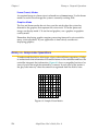
Pixel . . . . . . . . . . . . . . . . .
The Camera Imaging Surface . . . . . .
Resolution . . . . . . . . . . . . . .
Summary of Software Tools . . . . . . . . . .
Boundary Analysis . . . . . . . . . . .
Rulers . . . . . . . . . . . . . . . .
Inspection Windows . . . . . . . . . .
Finder Tools . . . . . . . . . . . . . .
Processing Windows . . . . . . . . . .
Modeling . . . . . . . . . . . . . . .
ObjectFinder . . . . . . . . . . . .
Overview of Guidance Vision . . . . . . . . .
Frames . . . . . . . . . . . . . . . .
Things to Consider When Designing Your Workcell
Consistent Environment . . . . . . . . .
Ease of Maintenance . . . . . . . . . .
Safety . . . . . . . . . . . . . . . .
Lighting . . . . . . . . . . . . . . .
2
.
.
.
.
.
.
.
.
.
.
.
.
.
.
.
.
.
.
.
.
.
.
.
.
.
.
.
.
.
.
.
.
.
.
.
.
.
.
.
.
.
.
.
.
.
.
.
.
.
.
.
.
.
.
.
.
.
.
.
.
.
.
.
.
.
.
.
.
.
.
.
.
.
.
.
.
.
.
.
.
.
.
.
.
.
.
.
.
.
.
.
.
.
.
.
.
.
.
.
.
.
.
.
.
.
.
.
.
.
.
.
.
.
.
.
.
.
.
.
.
.
.
.
.
.
.
.
.
.
.
.
.
.
.
.
.
.
.
.
.
.
.
.
.
.
.
.
.
.
.
.
.
.
.
.
.
.
.
.
.
.
.
.
.
.
.
.
.
.
.
.
.
.
.
.
.
.
.
.
.
.
.
.
.
.
.
.
.
.
.
.
.
.
.
.
.
.
.
.
.
.
.
.
.
.
.
.
.
.
.
.
.
.
.
.
.
.
.
.
.
.
.
.
.
.
.
.
.
.
.
.
.
.
.
.
.
.
.
.
.
.
.
.
.
.
.
.
.
.
.
.
.
.
.
.
.
.
.
.
.
.
.
.
.
.
.
.
.
.
.
.
.
.
.
.
.
.
.
.
.
.
.
.
.
.
.
Installation . . . . . . . . . . . . . . . . . . . . .
Setting up the Hardware . . . . . . . . . .
Installing the Controller . . . . . . . .
Attaching Cameras and Strobes . . . .
Strobe Compatibility. . . . . . . .
Cameras Supported by AdeptVision VXL
Panasonic GP-MF602 . . . . . . .
Panasonic GP-MF702 . . . . . . .
Pulnix TM-1001 . . . . . . . . . .
Sony XC-77 . . . . . . . . . . .
Mounting Cameras. . . . . . . . . .
Setting up the Software . . . . . . . . . . .
System Memory . . . . . . . . . . . . . .
6
.
.
.
.
.
.
.
.
.
.
.
.
.
.
.
.
.
.
.
.
.
.
.
.
.
.
.
.
.
.
.
.
.
.
.
.
.
.
.
.
.
.
.
.
.
.
.
.
.
.
AdeptVision User’s Guide, Rev. A
.
.
.
.
.
.
.
.
.
.
.
.
.
.
.
.
.
.
.
.
.
.
.
.
.
.
.
.
.
.
.
.
.
.
.
.
.
.
.
.
.
.
.
.
.
.
.
.
.
.
.
.
.
.
.
.
.
.
.
.
.
.
.
.
.
.
.
.
.
.
.
.
.
.
.
.
.
.
.
.
.
.
.
.
.
.
.
.
.
.
.
.
.
.
.
.
.
.
.
.
.
.
.
.
.
.
.
.
.
.
.
.
.
.
.
.
.
.
.
.
36
36
38
38
38
39
40
41
41
43
43
45
45
45
45
45
45
46
46
46
46
47
47
47
47
47
49
.
.
.
.
.
.
.
.
.
.
.
.
50
50
50
51
51
51
51
52
52
53
54
55
Table of Contents
3
Getting Started . . . . . . . . . . . . . . . . . . .
V+ Syntax Conventions . . . . . . . . . . . .
Virtual Cameras . . . . . . . . . . . . . . .
What Is a Virtual Camera?. . . . . . . .
How Are Camera Numbers Assigned? . .
Why Use Virtual Cameras? . . . . . . .
Motion Devices and Calibration . . . . . . . .
Calibration . . . . . . . . . . . . . .
Motion Device Calibration . . . . . .
Start-up Calibration . . . . . . . . .
Camera Calibration . . . . . . . . .
The Vision Transformation . . . . . . . .
Fixed-Mount Camera Transformation. .
Robot-Mounted Camera Transformation
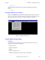
Loading Vision Calibration Data . . . . . . . .
4
.
.
.
.
.
.
.
.
.
.
.
.
.
.
.
.
.
.
.
.
.
.
.
.
.
.
.
.
.
.
.
.
.
.
.
.
.
.
.
.
.
.
.
.
.
.
.
.
.
.
.
.
.
.
.
.
.
.
.
.
.
.
.
.
.
.
.
.
.
.
.
.
.
.
.
.
.
.
.
.
.
.
.
.
.
.
.
.
.
.
.
.
.
.
.
.
.
.
.
.
.
.
.
.
.
.
.
.
.
.
.
.
.
.
.
.
.
.
.
.
.
.
.
.
.
.
.
.
.
.
.
.
.
.
.
.
.
.
.
.
.
.
.
.
.
.
.
.
.
.
.
.
.
.
Vision Calibration Overview . . . . . . . . . . . . . .
Compatibility . . . . . . . . . . . . . . . . . . . . . . .
Why Calibrate a Camera? . . . . . . . . . . . . . . . . .
Millimeter-to-Pixel Ratio . . . . . . . . . . . . . . . .
When Do I Need the Millimeter-to-Pixel Ratio? . . . . .
Perspective Distortion Corrections . . . . . . . . . . .
When Do I Need the Perspective Distortion Corrections?
Camera-to-Robot Transformation. . . . . . . . . . . .
Fixed-Mount Cameras . . . . . . . . . . . . . . .
Robot-Mounted Cameras . . . . . . . . . . . . .
Before You Start Calibrating Your Cameras . . . . . . . . . .
What You Need . . . . . . . . . . . . . . . . . . .
Calibration Object . . . . . . . . . . . . . . . .
What You Need to Do. . . . . . . . . . . . . . . . .
Things to Remember (Important Stuff) . . . . . . . . . .
When to Recalibrate the Camera . . . . . . . . . .
Virtual Cameras . . . . . . . . . . . . . . . . .
Resolution, Accuracy, and Repeatability . . . . . . .
5
.
.
.
.
.
.
.
.
.
.
.
.
.
.
57
.
.
.
.
.
.
.
.
.
.
.
.
.
.
.
.
.
.
.
.
.
.
.
.
.
.
.
.
.
.
.
.
.
.
.
.
.
.
.
.
.
.
.
.
.
.
.
.
.
.
.
.
.
.
.
.
.
.
.
.
.
.
.
.
.
.
.
.
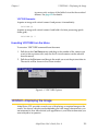
Using the Calibration Program . . . . . . . . . . . . .
58
59
59
60
60
60
60
61
61
61
61
61
62
63
65
.
.
.
.
.
.
.
.
.
.
.
.
.
.
.
.
.
66
66
66
68
69
69
70
70
70
71
71
71
73
73
73
74
74
77
ADV_CAL.V2 . . . . . . . . . . . . . . . . . . . . . . . . . . . . 78
ADV_USER.V2 . . . . . . . . . . . . . . . . . . . . . . . . . . . . 81
LOADAREA.V2 . . . . . . . . . . . . . . . . . . . . . . . . . . . . 82
AdeptVision User’s Guide, Rev. A
7
Table of Contents
6
The ADV_CAL Menus . . . . . . . . . . . . . . . . .
Introduction. . . . . . . . . . . . . . . . . . . . . . . . . . .
Calibration Status Display . . . . . . . . . . . . . . . . . . . . .
Main Menu . . . . . . . . . . . . . . . . . . . . . . . . . . .
Main Menu Options . . . . . . . . . . . . . . . . . . . .
Exit to system monitor . . . . . . . . . . . . . . . . . .
LOAD/STORE calibration data from/to disk . . . . . . . . .
ADJUST camera/image settings . . . . . . . . . . . . . .
CALIBRATE the current camera . . . . . . . . . . . . . .
TEST current calibration (camera-to-robot) . . . . . . . . .
COPY calibration between virtual cameras . . . . . . . . .
CHANGE virtual and/or physical cameras . . . . . . . . .
SELECT different robot . . . . . . . . . . . . . . . . . .
ADJUST Camera/Image Menu . . . . . . . . . . . . . . . . . . .
ADJUST Camera/Image Menu Options . . . . . . . . . . . .
RETURN to the main menu . . . . . . . . . . . . . . . .
ADJUST physical CAMERA ATTRIBUTES (live video) . . . . . .
ADJUST video GAIN and OFFSET (live video) . . . . . . . . .
ADJUST binary THRESHOLD (live binary) . . . . . . . . . . .
ADJUST vision WINDOW (processing boundaries) . . . . . . .
CALIBRATE the Current Camera Menu . . . . . . . . . . . . . . . .
CALIBRATE the Current Camera Menu Options . . . . . . . . .
Camera only . . . . . . . . . . . . . . . . . . . . . .
Stationary camera with robot—General method . . . . . . .
Calibration object attached to robot (general case) . . . . .
Downward-looking stationary camera (using vacuum gripper).
Object on moving belt (robot downstream of camera) . . . .
Robot mounted camera—Robot can touch calibration object .
Robot mounted camera—Known dot location . . . . . . . .
Robot mounted camera—Non-contact method . . . . . . .
Link-2 mounted camera—Robot can touch calibration object .
Link-2 mounted camera—Known dot location . . . . . . . .
Link-2 mounted camera—Non-contact method (single config.)
Link-2 mounted camera—Non-contact method (lefty/righty) .
LOAD/STORE Calibration Data Menu . . . . . . . . . . . . . . . .
LOAD/STORE Calibration Data From/To Disk Menu Options . . . .
LOAD calibration data from disk. . . . . . . . . . . . . .
STORE calibration data to disk. . . . . . . . . . . . . . .
8
AdeptVision User’s Guide, Rev. A
.
.
.
.
.
.
.
.
.
.
.
.
.
.
.
.
.
.
.
.
.
.
.
.
.
.
.
.
.
.
.
.
.
.
.
.
.
87
.
.
.
.
.
.
.
.
.
.
.
.
.
.
.
.
.
.
.
.
89
89
90
90
90
91
92
92
92
93
94
94
95
95
95
95
96
96
96
97
101
101
101
102
103
103
104
105
105
106
107
107
108
108
109
109
109
Table of Contents
7
Calibration Results . . . . . . . . . . . . . . . . . . 111
Introduction. . . . . . . . . . . . . . . . . . . . . . .
Vision Calibration Array. . . . . . . . . . . . . . . . . .
Perspective Transformations . . . . . . . . . . . . . . . .
Camera-to-Robot Transformation . . . . . . . . . . . . .
Miscellaneous Global Variables . . . . . . . . . . . . . .
Location Array ac.offset[ ] . . . . . . . . . . . . . .
Location Array ac.nominal[ ] and Real Array ac.config[ ] .
8
.
.
.
.
.
.
.
.
.
.
.
.
.
.
.
.
.
.
.
.
.
.
.
.
.
.
.
.
.
.
.
.
.
.
.
112
112
114
115
115
115
116
Teaching AdeptVision to See . . . . . . . . . . . . . 117
Introduction. . . . . . . . . . . . . .
Physical vs. Virtual Cameras . . . .
The Point of Origin . . . . . . . .
VPICTURE—Getting an Image . . . . . .
VPICTURE Syntax . . . . . . . . .
VPICTURE Examples . . . . . .
Executing VPICTURE From the Menu .
VDISPLAY—Displaying the Image. . . . .
VDISPLAY Syntax . . . . . . . . .
VDISPLAY Examples . . . . . .
Executing VDISPLAY From the Menu.
Using the Different Display Modes .
Live Modes . . . . . . . . .
Frame (Frozen) Modes . . . . .
Graphics Mode . . . . . . . .
Binary vs. Grayscale Operations . . . . .
Switches and Parameters . . . . . . . .
Using Switches . . . . . . . . . . . .
Enabling/Disabling Switches . . . .
Viewing Switch Settings . . . . . .
SWITCH Example . . . . . . .
Image-Acquisition Switches . . . .
Using Parameters . . . . . . . . . . .
Setting Parameters . . . . . . . .
Parameter Examples . . . . .
Image-Acquisition Parameters . . .
Examples of Switch and Parameter Settings
.
.
.
.
.
.
.
.
.
.
.
.
.
.
.
.
.
.
.
.
.
.
.
.
.
.
.
.
.
.
.
.
.
.
.
.
.
.
.
.
.
.
.
.
.
.
.
.
.
.
.
.
.
.
.
.
.
.
.
.
.
.
.
.
.
.
.
.
.
.
.
.
.
.
.
.
.
.
.
.
.
.
.
.
.
.
.
.
.
.
.
.
.
.
.
.
.
.
.
.
.
.
.
.
.
.
.
.
AdeptVision User’s Guide, Rev. A
.
.
.
.
.
.
.
.
.
.
.
.
.
.
.
.
.
.
.
.
.
.
.
.
.
.
.
.
.
.
.
.
.
.
.
.
.
.
.
.
.
.
.
.
.
.
.
.
.
.
.
.
.
.
.
.
.
.
.
.
.
.
.
.
.
.
.
.
.
.
.
.
.
.
.
.
.
.
.
.
.
.
.
.
.
.
.
.
.
.
.
.
.
.
.
.
.
.
.
.
.
.
.
.
.
.
.
.
.
.
.
.
.
.
.
.
.
.
.
.
.
.
.
.
.
.
.
.
.
.
.
.
.
.
.
.
.
.
.
.
.
.
.
.
.
.
.
.
.
.
.
.
.
.
.
.
.
.
.
.
.
.
.
.
.
.
.
.
.
.
.
.
.
.
.
.
.
.
.
.
.
.
.
.
.
.
.
.
.
.
.
.
.
.
.
.
.
.
.
.
.
.
.
.
.
.
.
.
.
.
.
.
.
.
.
.
.
.
.
.
.
.
.
.
.
.
.
.
.
.
.
.
.
.
.
.
.
.
.
.
.
.
.
.
.
.
.
.
.
.
.
.
.
.
.
.
.
.
.
.
.
.
.
.
.
.
.
.
.
.
118
118
119
120
120
121
121
121
122
122
123
123
123
124
124
124
128
129
129
129
130
130
131
131
131
131
133
9
Table of Contents
9
Boundary Analysis . . . . . . . . . . . . . . . . . . 141
Introduction. . . . . . . . . . . . . . . . . . . . . . .
Switches and Parameters Used During Boundary Analysis
Boundary Analysis Instructions . . . . . . . . . . . . . . .
VLOCATE . . . . . . . . . . . . . . . . . . . . .
VLOCATE Examples . . . . . . . . . . . . . . .
The DO Monitor Command . . . . . . . . . . . . .
VFEATURE . . . . . . . . . . . . . . . . . . . . .
What is VFEATURE? . . . . . . . . . . . . . . .
Blob Allocation . . . . . . . . . . . . . . . . .
VFEATURE Example . . . . . . . . . . . . . . .
VQUEUE . . . . . . . . . . . . . . . . . . . . .
10
.
.
.
.
.
.
.
.
.
.
.
.
.
.
.
.
.
.
.
.
.
.
.
.
.
.
.
.
.
.
.
.
.
.
.
.
.
.
.
.
.
.
.
.
142
142
144
144
145
146
146
146
148
148
149
Vision Tools . . . . . . . . . . . . . . . . . . . . . 151
Defining a Tool Area-of-Interest (AOI) . . . .
Frame Stores . . . . . . . . . . .
Virtual Frame Buffers. . . . . . .
Areas-of-Interest. . . . . . . . . .
Defining an Image Buffer Region .
Linear Rulers . . . . . . . . . . . . . .
VRULERI Array . . . . . . . . . . .
Linear Ruler Example . . . . . . . .
Arc Rulers . . . . . . . . . . . . . . .
Arc Ruler Example . . . . . . . . .
Ruler Types . . . . . . . . . . . . . . .
Standard Binary Rulers (type = 0) . . .
Raw Binary Rulers (type = –1) . . . .
Dynamic Binary Rulers (type = –2) . .
Graylevel Rulers (type = 1) . . . . .
Fine Edge/Fine Pitch Rulers (type = 2/3)
Ruler Speed and Accuracy . . . .
Finder Tools . . . . . . . . . . . . . . .
VFIND.LINE Array . . . . . . . . . .
Line Finder Tool Polarity . . . . . . .
VFIND.LINE Example . . . . . . . .
Processing Windows (VWINDOW). . . . . .
VWINDOW Example . . . . . . . .
Vision Tools: Inspection Windows (VWINDOWI)
Vision Tool Data Arrays . . . . . . . . . .
10
.
.
.
.
.
.
.
.
.
.
.
.
.
.
.
.
.
.
.
.
.
.
.
.
.
.
.
.
.
.
.
.
.
.
.
.
.
.
.
.
.
.
.
.
.
.
.
.
.
.
.
.
.
.
.
.
.
.
.
.
.
.
.
.
.
.
.
.
.
.
.
.
.
.
.
.
.
.
.
.
.
.
.
.
.
.
AdeptVision User’s Guide, Rev. A
.
.
.
.
.
.
.
.
.
.
.
.
.
.
.
.
.
.
.
.
.
.
.
.
.
.
.
.
.
.
.
.
.
.
.
.
.
.
.
.
.
.
.
.
.
.
.
.
.
.
.
.
.
.
.
.
.
.
.
.
.
.
.
.
.
.
.
.
.
.
.
.
.
.
.
.
.
.
.
.
.
.
.
.
.
.
.
.
.
.
.
.
.
.
.
.
.
.
.
.
.
.
.
.
.
.
.
.
.
.
.
.
.
.
.
.
.
.
.
.
.
.
.
.
.
.
.
.
.
.
.
.
.
.
.
.
.
.
.
.
.
.
.
.
.
.
.
.
.
.
.
.
.
.
.
.
.
.
.
.
.
.
.
.
.
.
.
.
.
.
.
.
.
.
.
.
.
.
.
.
.
.
.
.
.
.
.
.
.
.
.
.
.
.
.
.
.
.
.
.
.
.
.
.
.
.
.
.
.
.
.
.
.
.
.
.
.
.
.
.
.
.
.
.
.
.
.
.
.
.
.
.
.
.
.
.
.
.
.
.
.
.
.
.
.
.
.
.
.
.
152
152
152
153
155
158
158
159
161
161
164
164
164
164
165
165
166
166
167
167
168
170
170
171
171
Table of Contents
Windows, Windows, Windows . . . . . . . . . . . . . . . . . . . .
11
The ObjectFinder . . . . . . . . . . . . . . . . . . 173
Introduction. . . . . . . . . . . . . . .
How Does Object Recognition Work? . . . .
Feature Processing . . . . . . . . .
Hypothesis Generation . . . . . . .
Feature Classes. . . . . . . . .
Proposals . . . . . . . . . . .
Seeds . . . . . . . . . . . . .
Confirmation . . . . . . . . . . .
Pose Refinement . . . . . . . . . .
Verification . . . . . . . . . . . .
Max Verify Dist and Verify Percent .
Automatic Learning . . . . . . . . . . .
Object Disambiguation . . . . . . .
ObjectFinder Model File Format . . .
Automatic Learning Details . . . . . . . .
Stage One (VFINDER mode 4) . . . .
Stage Two (VFINDER mode 3) . . . .
Pose Refinement Details . . . . . . . . .
Object Disambiguation Details . . . . . . .
12
172
.
.
.
.
.
.
.
.
.
.
.
.
.
.
.
.
.
.
.
.
.
.
.
.
.
.
.
.
.
.
.
.
.
.
.
.
.
.
.
.
.
.
.
.
.
.
.
.
.
.
.
.
.
.
.
.
.
.
.
.
.
.
.
.
.
.
.
.
.
.
.
.
.
.
.
.
.
.
.
.
.
.
.
.
.
.
.
.
.
.
.
.
.
.
.
.
.
.
.
.
.
.
.
.
.
.
.
.
.
.
.
.
.
.
.
.
.
.
.
.
.
.
.
.
.
.
.
.
.
.
.
.
.
.
.
.
.
.
.
.
.
.
.
.
.
.
.
.
.
.
.
.
.
.
.
.
.
.
.
.
.
.
.
.
.
.
.
.
.
.
.
.
.
.
.
.
.
.
.
.
.
.
.
.
.
.
.
.
.
.
.
.
.
.
.
.
.
.
.
.
.
.
.
.
.
.
.
.
.
.
.
.
.
.
.
.
.
.
.
.
.
.
.
.
.
.
.
.
.
.
.
.
.
.
.
.
.
.
.
.
.
.
.
.
.
.
.
174
174
174
175
175
175
175
175
176
176
176
177
177
178
178
178
179
179
180
Vision Model Processing . . . . . . . . . . . . . . . 181
Introduction. . . . . . . . . . . . . . . . .
Why Use the ObjectFinder? . . . . . . .
Why Use Correlation? . . . . . . . . . .
Why Use Prototype Recognition? . . . . .
Why Use OCR? . . . . . . . . . . . .
Training and Using the ObjectFinder . . . . . .
Setting the System Switches and Parameters
Required Settings . . . . . . . . . .
Recommended Settings . . . . . . .
Creating an ObjectFinder Model . . . . .
Editing the Trained ObjectFinder Model . .
Planning the ObjectFinder Model . . . . .
Using the ObjectFinder . . . . . . . . .
Performing Correlation Matches . . . . . . . .
Creating a Correlation Template . . . . .
.
.
.
.
.
.
.
.
.
.
.
.
.
.
.
AdeptVision User’s Guide, Rev. A
.
.
.
.
.
.
.
.
.
.
.
.
.
.
.
.
.
.
.
.
.
.
.
.
.
.
.
.
.
.
.
.
.
.
.
.
.
.
.
.
.
.
.
.
.
.
.
.
.
.
.
.
.
.
.
.
.
.
.
.
.
.
.
.
.
.
.
.
.
.
.
.
.
.
.
.
.
.
.
.
.
.
.
.
.
.
.
.
.
.
.
.
.
.
.
.
.
.
.
.
.
.
.
.
.
.
.
.
.
.
.
.
.
.
.
.
.
.
.
.
.
.
.
.
.
.
.
.
.
.
.
.
.
.
.
.
.
.
.
.
.
.
.
.
.
.
.
.
.
.
183
183
184
184
185
186
186
186
186
187
187
187
188
189
189
11
Table of Contents
Matching a Correlation Template. . . . .
Training and Using Prototypes . . . . . . . . .
Creating Prototypes . . . . . . . . . .
Training Additional Instances . . . . . .
Editing Prototypes . . . . . . . . . . .
Preview Window . . . . . . . . . .
Zoom Buttons. . . . . . . . . . . .
Message Window . . . . . . . . . .
Edit Buttons . . . . . . . . . . . .
Editing Operation Data Box . . . . . .
Edge/Region Data Boxes. . . . . . .
Edge/Region Radio Buttons . . . . . .
Prototype Training Hints . . . . . . . . .
SubPrototypes . . . . . . . . . . . . .
Prototype Parameters. . . . . . . . . .
Setting Prototype Parameters . . . . .
Verify percent . . . . . . . . . . .
Effort level . . . . . . . . . . . . .
Min/max area . . . . . . . . . . .
Limit position . . . . . . . . . . . .
Edge weights. . . . . . . . . . . .
Assign cameras . . . . . . . . . .
Using Prototypes . . . . . . . . . . . .
Recognizing a Prototype . . . . . . .
Prototype-Relative Inspection . . . . .
Prototype-Relative Part Acquisition . .
Prototype Model Switches and Parameters . . .
Performing Optical Character Recognition . . . .
Training an OCR Font . . . . . . . . . .
Font Planning . . . . . . . . . . . . .
Character Recognition . . . . . . . . .
OCR Examples . . . . . . . . . . .
Loading and Storing Vision Models . . . . . . .
VSTORE . . . . . . . . . . . . . . . .
VLOAD . . . . . . . . . . . . . . . .
Displaying, Deleting, and Renaming Vision Models
Displaying Vision Models . . . . . . . .
Using the Vision Window Menus . . . .
From the V+ Monitor Prompt . . . . .
Deleting Vision Models . . . . . . . . .
12
.
.
.
.
.
.
.
.
.
.
.
.
.
.
.
.
.
.
.
.
.
.
.
.
.
.
.
.
.
.
.
.
.
.
.
.
.
.
.
.
AdeptVision User’s Guide, Rev. A
.
.
.
.
.
.
.
.
.
.
.
.
.
.
.
.
.
.
.
.
.
.
.
.
.
.
.
.
.
.
.
.
.
.
.
.
.
.
.
.
.
.
.
.
.
.
.
.
.
.
.
.
.
.
.
.
.
.
.
.
.
.
.
.
.
.
.
.
.
.
.
.
.
.
.
.
.
.
.
.
.
.
.
.
.
.
.
.
.
.
.
.
.
.
.
.
.
.
.
.
.
.
.
.
.
.
.
.
.
.
.
.
.
.
.
.
.
.
.
.
.
.
.
.
.
.
.
.
.
.
.
.
.
.
.
.
.
.
.
.
.
.
.
.
.
.
.
.
.
.
.
.
.
.
.
.
.
.
.
.
.
.
.
.
.
.
.
.
.
.
.
.
.
.
.
.
.
.
.
.
.
.
.
.
.
.
.
.
.
.
.
.
.
.
.
.
.
.
.
.
.
.
.
.
.
.
.
.
.
.
.
.
.
.
.
.
.
.
.
.
.
.
.
.
.
.
.
.
.
.
.
.
.
.
.
.
.
.
.
.
.
.
.
.
.
.
.
.
.
.
.
.
.
.
.
.
.
.
.
.
.
.
.
.
.
.
.
.
.
.
.
.
.
.
.
.
.
.
.
.
.
.
.
.
.
.
.
.
.
.
.
.
.
.
.
.
.
.
.
.
.
.
.
.
.
.
.
.
.
.
.
.
.
.
.
.
.
.
.
.
.
.
.
.
.
.
.
.
.
.
.
.
.
.
.
.
.
.
.
.
.
.
.
.
.
.
.
.
.
.
.
.
.
.
.
.
.
.
.
.
.
.
.
.
.
.
.
.
.
.
.
.
.
.
.
.
.
.
.
.
.
.
.
.
.
.
.
.
.
.
.
.
.
.
.
.
.
.
.
.
189
190
190
191
192
194
194
194
194
195
195
195
196
196
196
196
197
197
197
197
197
197
197
198
198
199
200
202
202
203
204
205
206
206
207
209
209
209
209
210
Table of Contents
Using the Vision Window Menus . . . . . . .
From the V+ Monitor Prompt . . . . . . . .
Renaming Vision Models . . . . . . . . . . .
Using the Vision Window Menus . . . . . . .
From the V+ Monitor Prompt . . . . . . . .
ObjectFinder Example . . . . . . . . . . . . . . .
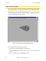
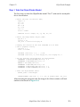
Step 1: Train the ObjectFinder Model . . . . . .
Step 2: Plan the ObjectFinder Model . . . . . .
Step 3: Use the ObjectFinder to Locate the Object
Prototype Finder Example . . . . . . . . . . . . . .
Step 1: Train the Prototype Finder Model . . . . .
Step 2: Train Additional Instances . . . . . . . .
Step 3: Use the Prototype Finder to Locate a Part .
13
Programming AdeptVision VXL
Guidance Vision
.
.
.
.
.
.
.
.
.
.
.
.
.
.
.
.
.
.
.
.
.
.
.
.
.
.
.
.
.
.
.
.
.
.
.
.
.
.
.
.
.
.
.
.
.
.
.
.
.
.
.
.
.
.
.
.
.
.
.
.
.
.
.
.
.
.
.
.
.
.
.
.
.
.
.
.
.
.
.
.
.
.
.
.
.
.
.
.
.
.
.
210
210
210
210
211
212
213
215
216
219
219
220
222
. . . . . . . . . . . . 225
Introduction. . . . . . . . . . . . . . . . . .
Application Development Strategy . . . . . . . .
Vision Inspection Example Program . . . . . . .
Developing the Program Code. . . . . . . . . .
Program Header and Variables Declarations .
Set the Camera Environment . . . . . .
Acquire an Image and Start Processing .
Locate the Object and Begin Inspections .
Output the Results . . . . . . . . . . .
Further Programming Considerations . . . .
The Complete Inspection Vision Program . . . . .
The Main Program - inspect.part . . . . . .
Subroutine - line.line( ) . . . . . . . . . .
Subroutine - init.program( ) . . . . . . . .
Subroutine - write.vwin( ) . . . . . . . . .
14
.
.
.
.
.
.
.
.
.
.
.
.
.
.
.
.
.
.
.
.
.
.
.
.
.
.
.
.
.
.
.
.
.
.
.
.
.
.
.
.
.
.
.
.
.
.
.
.
.
.
.
.
.
.
.
.
.
.
.
.
.
.
.
.
.
.
.
.
.
.
.
.
.
.
.
.
.
.
.
.
.
.
.
.
.
.
.
.
.
.
.
.
.
.
.
.
.
.
.
.
.
.
.
.
.
.
.
.
.
.
.
.
.
.
.
.
.
.
.
.
.
.
.
.
.
.
.
.
.
.
.
.
.
.
.
.
.
.
.
.
.
.
.
.
.
.
.
.
.
.
.
.
.
.
.
.
.
.
.
.
.
.
.
226
226
227
230
230
231
232
233
240
242
243
243
250
252
253
. . . . . . . . . . . . . . . . . . 255
Introduction. . . . . . . . . . . . . . .
Using a Fixed-Mount Camera . . . . . . .
4-Axis SCARA Robot with Camera on Link #2
5-Axis SCARA Robot with Camera on Link #2 .
Guidance Vision Program . . . . . . . . .
The Sample Program . . . . . . . .
Further Programming Considerations . . . .
.
.
.
.
.
.
.
.
.
.
.
.
.
.
.
.
.
.
.
.
.
AdeptVision User’s Guide, Rev. A
.
.
.
.
.
.
.
.
.
.
.
.
.
.
.
.
.
.
.
.
.
.
.
.
.
.
.
.
.
.
.
.
.
.
.
.
.
.
.
.
.
.
.
.
.
.
.
.
.
.
.
.
.
.
.
.
.
.
.
.
.
.
.
.
.
.
.
.
.
.
256
257
261
266
268
269
278
13
Table of Contents
Error Handling . . . . . . . . . . . . . . . . . . . . . . . .
Generalizing the Program . . . . . . . . . . . . . . . . . . .
15
Advanced Operations . . . . . . . . . . . . . . . . 281
Performing High-Speed Inspections. . . . . . .
What is “High Speed”? . . . . . . . . .
Using the Two Frame Store Areas . . . . .
Using VPICTURE With Different Frame Stores.
Using VDISPLAY With Different Frame Stores.
Sample Code for a High-Speed Inspection.
The High-Speed Trigger . . . . . . . . .
Performing Frame-Relative Inspections . . . . .
Blob-Relative Inspection . . . . . . . .
Prototype-Relative Inspection . . . . . .
Frame-Relative Inspections Using VDEF.TRANS . .
Using a Vision-Guided Tracking Conveyor . . . .
A
.
.
.
.
.
.
.
.
.
.
.
.
.
.
.
.
.
.
.
.
.
.
.
.
.
.
.
.
.
.
.
.
.
.
.
.
.
.
.
.
.
.
.
.
.
.
.
.
.
.
.
.
.
.
.
.
.
.
.
.
.
.
.
.
.
.
.
.
.
.
.
.
.
.
.
.
.
.
.
.
.
.
.
.
.
.
.
.
.
.
.
.
.
.
.
.
.
.
.
.
.
.
.
.
.
.
.
.
.
.
.
.
.
.
.
.
.
.
.
.
.
.
.
.
.
.
.
.
.
.
.
.
VFEATURE( ) Values
.
.
.
.
.
.
.
.
.
.
.
.
.
.
.
.
.
.
.
.
.
.
.
.
.
.
.
.
.
.
.
.
.
.
.
.
.
.
.
.
.
.
.
.
.
.
.
.
.
.
.
.
.
.
.
.
.
.
.
.
.
.
.
.
.
.
.
.
.
.
.
.
.
.
.
.
.
.
.
.
.
.
.
.
.
.
.
.
.
.
.
.
.
.
.
.
.
.
.
.
.
.
.
.
.
.
.
.
.
.
.
.
.
.
.
.
.
.
.
.
.
.
.
.
.
.
.
.
.
.
.
.
Lens Selection
312
312
314
Lighting Considerations . . . . . . . . . . . . . . . . 317
Types of Lighting . . . . . . . . . . . . . . . . . . . . . . . . . .
Lighting Strategies . . . . . . . . . . . . . . . . . . . . . . . . .
14
302
302
. . . . . . . . . . . . . . . . . . . 311
Introduction. . . . . . . . . . . . . . . . . . . . . . . . . . . .
Formula for Focal Length . . . . . . . . . . . . . . . . . . . . . .
Formula for Resolution . . . . . . . . . . . . . . . . . . . . . . .
D
294
294
294
295
295
298
. . . . . . . . . . . . . . . . . 301
Viewing VFEATURE( ) Values . . . . . . . . . . . . . . . . . . . . .
Establishing VFEATURE( ) Values . . . . . . . . . . . . . . . . . . .
C
282
282
283
283
284
284
286
287
287
289
290
292
Switches and Parameters . . . . . . . . . . . . . . . 293
Setting Vision Switches .
Viewing Switch Settings
Setting Vision Parameters
Viewing Parameters . .
List of Switches . . . .
List of Parameters . . .
B
278
278
AdeptVision User’s Guide, Rev. A
318
318
Table of Contents
Diffuse . . . . . .
Back . . . . . . .
Directional . . . .
Structured . . . .
Strobe . . . . . .
Filtering and Special Effects
Polarizing Filters . .
Color Filters . . . .
E
.
.
.
.
.
.
.
.
.
.
.
.
.
.
.
.
.
.
.
.
.
.
.
.
.
.
.
.
.
.
.
.
.
.
.
.
.
.
.
.
.
.
.
.
.
.
.
.
.
.
.
.
.
.
.
.
.
.
.
.
.
.
.
.
.
.
.
.
.
.
.
.
.
.
.
.
.
.
.
.
.
.
.
.
.
.
.
.
.
.
.
.
.
.
.
.
.
.
.
.
.
.
.
.
.
.
.
.
.
.
.
.
.
.
.
.
.
.
.
.
.
.
.
.
.
.
.
.
.
.
.
.
.
.
.
.
.
.
.
.
.
.
.
.
.
.
.
.
.
.
.
.
.
.
.
.
.
.
.
.
.
.
.
.
.
.
.
.
Calibrating With HPS Data . . . . . . . . . . . . . . . 321
Introduction. . . . . . . . . . . . . . . . . . . . . . . . . . . .
Using HPS Data . . . . . . . . . . . . . . . . . . . . . . . . . .
F
326
327
Camera Calibration Programs . . . . . . . . . . . . . 329
adv.cam.sample( ) . . . . . .
ac.refine.vloc( ) . . . . . . . .
adv.cam.user( ) and adv.tr.point( )
adv.cam.user( ) . . . . .
adv.tr.point( ) . . . . . .
H
322
322
Calibration Target Dimensions . . . . . . . . . . . . . 325
The Calibration Target . . . . . . . . . . . . . . . . . . . . . . .
Using a Custom Calibration Sheet . . . . . . . . . . . . . . . . . .
G
318
319
319
319
319
320
320
320
.
.
.
.
.
.
.
.
.
.
.
.
.
.
.
.
.
.
.
.
.
.
.
.
.
.
.
.
.
.
.
.
.
.
.
.
.
.
.
.
.
.
.
.
.
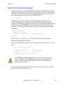
.
.
.
.
.
.
.
.
.
.
.
.
.
.
.
.
.
.
.
.
.
.
.
.
.
.
.
.
.
.
.
.
.
.
.
.
.
.
.
.
.
.
.
.
.
330
331
333
333
336
Pulnix TM-1001 Configuration . . . . . . . . . . . . . 339
Introduction. . . . . . . . . . . . . .
Overview . . . . . . . . . . . . . . .
Switch Settings . . . . . . . . . . . .
DSP/NSP Switch . . . . . . . . .
NRM/ASY Switch . . . . . . . . .
Shutter Control . . . . . . . . .
For Asynchronous Reset Mode .
For Normal (Synchronous) Mode
EVI Board Settings . . . . . . . . . . .
Camera Cables . . . . . . . . . . . .
Changes to Frame Buffer Size . . . . . .
Blob Analysis Using the Pulnix TM-1001 . .
.
.
.
.
.
.
.
.
.
.
.
.
.
.
.
.
.
.
.
.
.
.
.
.
.
.
.
.
.
.
.
.
.
.
.
.
.
.
.
.
.
.
.
.
.
.
.
.
AdeptVision User’s Guide, Rev. A
.
.
.
.
.
.
.
.
.
.
.
.
.
.
.
.
.
.
.
.
.
.
.
.
.
.
.
.
.
.
.
.
.
.
.
.
.
.
.
.
.
.
.
.
.
.
.
.
.
.
.
.
.
.
.
.
.
.
.
.
.
.
.
.
.
.
.
.
.
.
.
.
.
.
.
.
.
.
.
.
.
.
.
.
.
.
.
.
.
.
.
.
.
.
.
.
.
.
.
.
.
.
.
.
.
.
.
.
.
.
.
.
.
.
.
.
.
.
.
.
340
340
341
341
341
342
342
342
343
343
343
344
15
Table of Contents
I
Using DEVICE With Vision . . . . . . . . . . . . . . . 345
Introduction. . . . . . . . . . . . . . . . . . . . . .
The DEVICE Instruction With Vision . . . . . . . . . . . .
Defective Pixel Compensation . . . . . . . . . . .
Writing a Table Entry . . . . . . . . . . . . . .
Reading a Table Entry . . . . . . . . . . . . .
Resetting a Table Entry . . . . . . . . . . . . .
Error Information . . . . . . . . . . . . . . .
Example: Changing the Number of Virtual Frame Stores
J
K
L
.
.
.
.
.
.
.
.
.
.
.
.
.
.
.
.
.
.
.
.
.
.
.
.
.
.
.
.
.
.
.
.
.
.
.
.
.
.
.
.
.
.
.
.
.
.
.
.
346
346
349
349
350
350
350
351
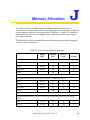
Memory Allocation . . . . . . . . . . . . . . . . . 353
Vision Window Menus . . . . . . . . . . . . . . . . 355
Third-Party Suppliers . . . . . . . . . . . . . . . . . 361
Third-Party Suppliers (U.S.) . . . . . . . . . . . . . . . . . . . . .
Third-Party Suppliers (Europe) . . . . . . . . . . . . . . . . . . . .
Third-Party Suppliers (Asia-Pacific) . . . . . . . . . . . . . . . . . .
362
366
370
Index . . . . . . . . . . . . . . . . . . . . . . . 373
16
AdeptVision User’s Guide, Rev. A
List of Figures
Figure 1
Figure 1-1
Figure 1-2
Figure 1-3
Figure 1-4
Figure 1-5
Figure 2-1
Figure 3-1
Figure 3-2
Figure 4-1
Figure 4-2
Figure 8-1
Figure 8-2
Figure 8-3
Figure 8-4
Figure 8-5
Figure 8-6
Figure 8-7
Figure 8-8
Figure 8-9
Figure 8-10
Figure 8-11
Figure 8-12
Figure 10-1
Figure 10-2
Figure 10-3
Figure 10-4
Figure 10-5
Figure 10-6
Figure 10-7
Figure 10-8
Figure 10-9
Figure 10-10
Figure 10-11
Figure 10-12
Figure 12-1
Figure 12-2
Figure 12-3
Figure 12-4
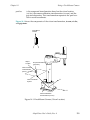
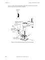
Impact and Trapping Hazards . . . . . . .
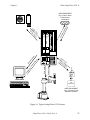
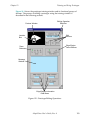
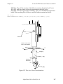
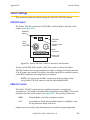
Typical AdeptVision VXL System . . . . . .
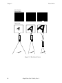
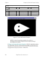
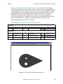
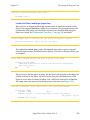
Sample Object . . . . . . . . . . . . .
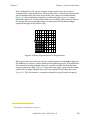
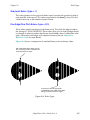
A Grayscale Image . . . . . . . . . . .
A Binary Image . . . . . . . . . . . . .
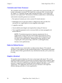
Resolution Factors . . . . . . . . . . . .
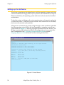
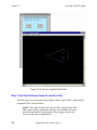
Initial Screen . . . . . . . . . . . . . .
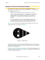
Sample Operation. . . . . . . . . . . .
Physical/Virtual Camera Relationship . . .
Millimeter-to-Pixel Ratio . . . . . . . . .
Perspective Distortion . . . . . . . . . .
VPICTURE Options . . . . . . . . . . . .
Display Mode Options . . . . . . . . . .
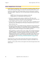
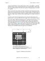
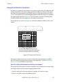
Sample Vision Matrix . . . . . . . . . .
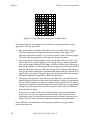
Binary Representation of Sample Matrix. . .
Grayscale Representation of Sample Matrix .
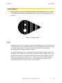
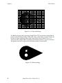
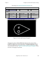
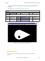
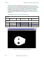
Sample Object . . . . . . . . . . . . .
Switch and Parameter Example 1 . . . . .
Switch and Parameter Example 2 . . . . .
Switch and Parameter Example 3 . . . . .
Switch and Parameter Example 4 . . . . .
Switch and Parameter Example 5 . . . . .
Switch and Parameter Example 6 . . . . .
Rectangular Area-of-Interest Shapes . . . .
Arc-Shaped Area-of-Interest Shapes . . . .
Sample Area-of-Interest . . . . . . . . .
Sample Image Buffer Regions . . . . . . .
Linear Ruler Example . . . . . . . . . .
Sample Gauge Face . . . . . . . . . .
Arc Ruler Example. . . . . . . . . . . .
Ruler Types . . . . . . . . . . . . . . .
Line Finder Search Area . . . . . . . . .
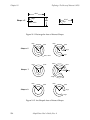
Finder Tool Polarity . . . . . . . . . . .
Line Finder Example . . . . . . . . . . .
VWINDOW Example . . . . . . . . . . .
Prototype Editing Operations . . . . . . .
Font Similarity Matrix . . . . . . . . . . .
Sample Part for ObjectFinder Training . . .
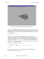
Example ObjectFinder Model After Training .
AdeptVision User’s Guide, Rev. A
.
.
.
.
.
.
.
.
.
.
.
.
.
.
.
.
.
.
.
.
.
.
.
.
.
.
.
.
.
.
.
.
.
.
.
.
.
.
.
.
.
.
.
.
.
.
.
.
.
.
.
.
.
.
.
.
.
.
.
.
.
.
.
.
.
.
.
.
.
.
.
.
.
.
.
.
.
.
.
.
.
.
.
.
.
.
.
.
.
.
.
.
.
.
.
.
.
.
.
.
.
.
.
.
.
.
.
.
.
.
.
.
.
.
.
.
.
.
.
.
.
.
.
.
.
.
.
.
.
.
.
.
.
.
.
.
.
.
.
.
.
.
.
.
.
.
.
.
.
.
.
.
.
.
.
.
.
.
.
.
.
.
.
.
.
.
.
.
.
.
.
.
.
.
.
.
.
.
.
.
.
.
.
.
.
.
.
.
.
.
.
.
.
.
.
.
.
.
.
.
.
.
.
.
.
.
.
.
.
.
.
.
.
.
.
.
.
.
.
.
.
.
.
.
.
.
.
.
.
.
.
.
.
.
.
.
.
.
.
.
.
.
.
.
.
.
.
.
.
.
.
.
.
.
.
.
.
.
.
.
.
.
.
.
.
.
.
.
.
.
.
.
.
30
37
41
42
42
44
54
58
59
67
69
121
123
124
125
126
133
134
135
136
137
138
139
154
154
156
157
160
161
163
165
167
168
169
171
193
204
212
214
17
Table of Contents
Figure 12-5
Figure 12-6
Figure 12-7
Figure 12-8
Figure 12-9
Figure 12-10
Figure 13-1
Figure 13-2
Figure 13-3
Figure 13-4
Figure 13-5
Figure 14-1
Figure 14-2
Figure 14-3
Figure 14-4
Figure 14-5
Figure 14-6
Figure 14-7
Figure 14-8
Figure 15-1
Figure 15-2
Figure C-1
Figure C-2
Figure H-1
18
Example ObjectFinder Model After Planning. . .
Example Found Object. . . . . . . . . . . .
Example Monitor Window Display . . . . . . .
Trained Prototype Model . . . . . . . . . . .
Selecting Reference Corners for Prototype Finder.
Instance Aligned With Model . . . . . . . . .
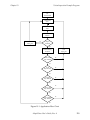
Application Flow Chart . . . . . . . . . . . .
Executing the VWINDOW Instruction . . . . . .
Executing a VFIND.LINE Instruction . . . . . . .
Executing a VFIND.ARC Instruction . . . . . . .
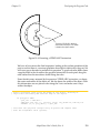
Calculating the Object Tail Location . . . . . .
Fixed-Mount Camera (Vision Location) . . . . .
Fixed-Mount Camera Vision Transformation . . .
Link2 Coordinate Frame . . . . . . . . . . .
Calculating the Link2 Transformation . . . . . .
Components of the Vision Location . . . . . .
Final Part Acquire Location . . . . . . . . . .
Five-Axis Vision Transformation . . . . . . . .
Example Program Setup . . . . . . . . . . .
Ping-Pong Frame Grabbing . . . . . . . . . .
Blob-Relative Inspection . . . . . . . . . . .
Camera Imaging . . . . . . . . . . . . . .
Camera Scale Factor . . . . . . . . . . . .
Pulnix TM-1001 Camera Connectors and Switches
AdeptVision User’s Guide, Rev. A
.
.
.
.
.
.
.
.
.
.
.
.
.
.
.
.
.
.
.
.
.
.
.
.
.
.
.
.
.
.
.
.
.
.
.
.
.
.
.
.
.
.
.
.
.
.
.
.
.
.
.
.
.
.
.
.
.
.
.
.
.
.
.
.
.
.
.
.
.
.
.
.
.
.
.
.
.
.
.
.
.
.
.
.
.
.
.
.
.
.
.
.
.
.
.
.
.
.
.
.
.
.
.
.
.
.
.
.
.
.
.
.
.
.
.
.
.
.
.
.
216
217
218
220
221
222
229
234
237
239
251
259
260
263
264
265
266
267
269
283
289
313
313
341
List of Tables
Table 7-1
Table 8-1
Table 8-2
Table 9-1
Table 9-2
Table 9-3
Table 12-1
Table 12-2
Table A-1
Table A-2
Table B-1
Table B-2
Table B-3
Table B-4
Table C-1
Table D-1
Table F-1
Table H-1
Table I-1
Table I-2
Table J-1
Table L-1
Table L-2
Table L-3
Table L-4
Table L-5
Table L-6
Table L-7
Table L-8
Table L-9
Table L-10
Table L-11
Table L-12
Elements of Vision Calibration Array . . . . . . . .
Image-Acquisition Switches . . . . . . . . . . .
Image-Acquisition Parameters . . . . . . . . . .
Boundary Analysis Switches . . . . . . . . . . .
Boundary Analysis Parameter . . . . . . . . . . .
VFEATURE Values and Interpretation . . . . . . . .
Prototype Model Switches . . . . . . . . . . . .
Prototype Model Parameters . . . . . . . . . . .
Vision Switches . . . . . . . . . . . . . . . . .
Vision Parameters . . . . . . . . . . . . . . .
VFEATURE( ) Values and Interpretation for ObjectFinder
Recognition Instances (following VLOCATE) . . .
VFEATURE( ) Values and Interpretation for ObjectFinder
Models (following VSHOW) . . . . . . . . . .
VFEATURE( ) Values and Interpretation for Prototype
Recognition Instances (following VLOCATE) . . .
VFEATURE( ) Values and Interpretation for Prototype
Recognition Instances (following VSHOW) . . .
Camera Scale Factors . . . . . . . . . . . . . .
Types of Lighting . . . . . . . . . . . . . . . .
Adept Calibration Sheet Dimensions . . . . . . . .
Shutter Dial Settings for Asynchronous Mode. . . . .
DEVICE Input/Output Format . . . . . . . . . . .
Vision Memory Allocation . . . . . . . . . . . .
Vision System Memory Allocation . . . . . . . . .
Fiber Optic Lighting Suppliers . . . . . . . . . . .
Lighting Suppliers . . . . . . . . . . . . . . . .
Camera Equipment Suppliers . . . . . . . . . . .
Frame Splitter Suppliers . . . . . . . . . . . . .
Camera Suppliers . . . . . . . . . . . . . . . .
Filter and Optics Suppliers . . . . . . . . . . . .
Lens Suppliers . . . . . . . . . . . . . . . . .
Mounting Hardware Suppliers . . . . . . . . . . .
Lighting Suppliers . . . . . . . . . . . . . . . .
Lens Suppliers . . . . . . . . . . . . . . . . .
Filter and Optics Suppliers . . . . . . . . . . . .
Lighting, Filter, and Optics Suppliers . . . . . . . .
AdeptVision User’s Guide, Rev. A
.
.
.
.
.
.
.
.
.
.
.
.
.
.
.
.
.
.
.
.
.
.
.
.
.
.
.
.
.
.
112
130
132
142
143
147
200
201
295
298
. . . 303
. . . 304
. . . 306
.
.
.
.
.
.
.
.
.
.
.
.
.
.
.
.
.
.
.
.
.
.
.
.
.
.
.
.
.
.
.
.
.
.
.
.
.
.
.
.
.
.
.
.
.
.
.
.
.
.
.
.
.
.
.
.
.
.
.
.
308
314
318
326
342
348
348
353
362
363
363
364
364
365
365
366
366
367
368
370
19
Introduction
Compatibility . . . . . . . . . . . . . . . . . . . . . . . . . . . .
22
What’s New in AdeptVision VXL Version 13.0 . . . . . . . . . . . . .
23
ObjectFinder Changes . . . . . . . . . .
Feature-based Refinement . . . . .
Improved Handling of Complex Parts
Other Vision Changes . . . . . . . . . . .
Keyword Changes . . . . . . . . . . . .
.
.
.
.
.
23
23
23
24
24
. . . . . . . . . . . . . . . . . . . . . . .
25
Organization . . . . . . . . . . . . . . . . . . . . . . . . .
Before You Begin . . . . . . . . . . . . . . . . . . . . . . .
Related Manuals . . . . . . . . . . . . . . . . . . . . . . .
25
26
26
Safety . . . . . . . . . . . . . . . . . . . . . . . . . . . . . . . .
28
How to Use This Manual
.
.
.
.
.
.
.
.
.
.
.
.
.
.
.
.
.
.
.
.
.
.
.
.
.
.
.
.
.
.
.
.
.
.
.
.
.
.
.
.
Reading and Training for Users and Operators . . . . . . .
System Safeguards . . . . . . . . . . . . . . . . . . . .
Safety Features on the Controller Interface Panel (CIP)
Computer-Controlled Robots and Motion
Devices (Automatic mode) . . . . . . . . . .
Manually Controlled Robots and Motion Devices . .
Other Computer-Controlled Devices . . . . . . . .
Program Security . . . . . . . . . . . . . . . . . . . . .
Overspeed Protection . . . . . . . . . . . . . . . . . . .
Voltage Interruptions . . . . . . . . . . . . . . . . . . .
Inappropriate Uses of the AdeptWindows Controller System
.
.
.
.
.
. .
. .
. .
28
29
29
.
.
.
.
.
.
.
.
.
.
.
.
.
.
29
29
30
30
31
31
31
. . . . . . . . . . . . . . . . . . .
31
Hypertext Links in Online Manuals . . . . . . . . . . . . . . . . . .
32
Links to Cross References . . . . . . . . . . . . . . . . . . .
Links to Related Manuals . . . . . . . . . . . . . . . . . . .
Links to Related Keywords . . . . . . . . . . . . . . . . . . .
32
32
33
Notes, Cautions, and Warnings
How Can I Get Help?
. . . . . . . . . . . . . . . . . . . . . . . .
AdeptVision User’s Guide, Rev. A
33
21
Introduction
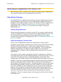
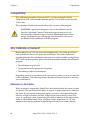
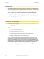
Compatibility
Compatibility
This manual is for use with V+ systems equipped with the AdeptVision software
and hardware options. The system version must be 13.0 or later running on an
AdeptWindows Controller (AWC).
This manual is intended primarily for vision application programmers. If your
system includes the optional VisionWare or MotionWare with vision software,
you do not need to read this manual. However, many principles of machine vision
and AdeptVision VXL processing are covered in greater detail here than in the
VisionWare or MotionWare user’s guides, so a general review of this manual
may be useful.
22
AdeptVision User’s Guide, Rev. A
Introduction
What’s New in AdeptVision VXL Version 13.0
What’s New in AdeptVision VXL Version 13.0
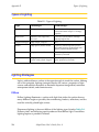
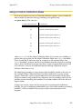
This section provides a summary of the software changes made to AdeptVision
VXL since this manual was last published for version 12.1.
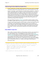
ObjectFinder Changes
The ObjectFinder was enhanced to provide new features and better performance
during refinement and learning. Also, the ObjectFinder model file format was
changed so that models created in version 12.3 and later will be compatible with
all future versions of AdeptVision. See Chapter 11 for an overview of the
ObjectFinder. Also, see Chapter 12 for details and examples on using the
ObjectFinder in V+.
Feature-based Refinement
Feature-based refinement was added in version 12.2 to increase significantly the
accuracy of alignment for instances found with the ObjectFinder. In version 12.3,
the calculation for pose refinement has been improved to provide a better
estimate of the orientation of elongated parts. See “Pose Refinement Details” on
page 179 for details.
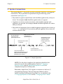
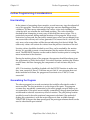
Improved Handling of Complex Parts
Version 13.0 of ObjectFinder includes new techniques for improving the
recognition speed of large, complex parts that may contain more than a hundred
features and thousands of pairs. Complex parts might produce too many
proposals at runtime, resulting in very slow recognition. The new techniques
added to ObjectFinder 13.0 compile complex models into more efficient
recognition plans, leading to faster recognition plans than previous versions of
ObjectFinder.
The number of pairs used for generating proposals is reduced to a smaller set
containing the pairs that are most likely to generate successful proposals. The size
of the pair set is reduced without sacrificing reliability and accuracy. With
complex parts, the number of pairs can be reduced from thousands to less than a
hundred. The process of generating proposals has been improved by evaluating
features for pair generation in a better order to produce successful proposals
much earlier in the recognition process. During recognition, pairs that have been
identified during planning as being very likely to lead to successful proposals
bypass the confirmation step, reducing the amount of time spent evaluating the
proposal. New geometric constraints have been added to pair generation to
avoid generating weak proposals from small features or features that are too far
apart, thus reducing the time spent generating and matching pairs during
recognition. The new strategies improve the recognition times for both complex
and simple parts.
AdeptVision User’s Guide, Rev. A
23
Introduction
What’s New in AdeptVision VXL Version 13.0
These new recognition strategies are applied automatically and do not require
any changes to existing V+ programs. The new recognition strategies enlarge the
range of parts for which ObjectFinder is suitable, improving performance across
the entire range from simple parts to more complex parts.
Other Vision Changes
Vision tasks are now scheduled so that they do not interfere with the tasks that
update the image data for AdeptWindows.
Keyword Changes
The following AdeptVision keywords were changed since this manual was last
published:
VCOPY (program instruction)
VFEATURE (real-valued function)
VFINDER (real-valued function)
VGETCAL (program instruction)
VPUTCAL (program instruction)
VTRAIN.FINDER (program instruction)
See the AdeptVision Reference Guide for details.
24
AdeptVision User’s Guide, Rev. A
Introduction
How to Use This Manual
How to Use This Manual
Organization
Material in this manual is presented in a step-by-step fashion. Each chapter
expands on and relies on information in the preceding chapters. If you are new to
machine vision systems, this manual will take you from the conceptual basis for
machine vision to advanced programming techniques in computer vision
applications. Here is what you will find in each of the chapters:
Chapter 1
presents an overview of machine vision principles and introduces
vocabulary and concepts you will need when reading the other
chapters.
Chapter 2
shows you how to physically set up the AdeptVision VXL system
hardware.
Chapter 3
shows you how to perform all the initialization tasks necessary to
get your system ready to start developing vision applications.
Chapter 4
provides an overview of vision system calibration. The vision system should always be calibrated prior to any application development.
Chapter 5
describes the overall procedure for executing the Advanced Camera
Calibration program (ADV_CAL.V2).
Chapter 6
describes each of the selections in the ADV_CAL menus.
Chapter 7
describes the data generated during the calibration process. This
data includes calibration arrays, perspective transformations, and
(for robot-related calibrations) camera-to-robot transformations.
Chapter 8
introduces vision processing. It describes how to acquire and process an image. You will learn to fine-tune the images you produce so
your vision applications run as efficiently and predictably as possible.
Chapter 9
describes the first vision processing strategy, boundary analysis.
You will learn where vision data is stored and how you can influence the data the vision system gathers.
Chapter 10
describes the second vision processing strategy, vision tools. You
will learn to use rulers, finders, and inspection windows.
AdeptVision User’s Guide, Rev. A
25
Introduction
How to Use This Manual
Chapter 11
provides an overview of the ObjectFinder.
Chapter 12
describes the vision modeling process, including ObjectFinder recognition, prototype recognition, optical character recognition
(OCR), and correlation templates.
Chapter 13
presents a sample program. You will learn how to combine the
knowledge gained in the previous chapters to program an inspection vision application.
Chapter 14
covers using the vision system to guide a motion device. You will
learn how to set up and calibrate cameras that will locate, acquire,
and place parts. If you do not have a motion device, you can skip
this chapter.
Chapter 15
discusses advanced topics in vision processing. High-speed inspections, part-relative inspections, and conveyor operations are covered.
Before You Begin
AdeptVision VXL is an extension of the V+ operating system and language. In
order to use the AdeptVision VXL extension you must be familiar with the basic
V+ operating system and language. In particular, this manual assumes that you:
• Are familiar with the Adept graphical user interface.
• Can use the SEE program editor or the AdeptWindows Offline Editor to create
and edit programs.
• Are familiar with V+ programming, including control structures, data types,
and subroutine principles.
The V+ operating system and graphical user interface are covered in the V+
Operating System User’s Guide and the V+ Operating System Reference Guide.
The V+ language is covered in the V+ Language User’s Guide and the V+ Language
Reference Guide.
Related Manuals
There are several manuals you should have handy as you use this manual. They
are:
• The V+ Operating System User’s Guide, which covers operating system tasks
such as copying files, executing programs, and using the graphical interface.
• The V+ Operating System Reference Guide, which details the operating system
commands (known as monitor commands).
26
AdeptVision User’s Guide, Rev. A
Introduction
How to Use This Manual
• The V+ Language User’s Guide and the V+ Language Reference Guide, which
contain a complete description of the commands, instructions, functions, and
other features available in the V+ language. These manuals are essential for
advanced applications programming.
• The AdeptVision Reference Guide, which contains a complete description of the
vision enhancements to the V+ language. This manual is a companion guide to
the AdeptVision User’s Guide.
• The Instructions for Adept Utility Programs, many of which are referenced in
this manual.
• The Adept MV Controller User’s Guide. This manual contains information on
installing, maintaining, and configuring the physical controller hardware.
• The AdeptWindows User’s Guide. This manual contains information on
installing and using the AdeptWindows software package. This software
allows you to use a PC front end with the AdeptWindows Controller (AWC). It
also allows you to write and edit V+ code offline using the PC.
• The user’s guide for your robot or motion device (if your system includes a
motion device). This manual contains information on installing, maintaining,
and calibrating the motion device.
• The manuals for any options you have purchased with the system (such as
VisionWare), or purchased separately to use with the system.
AdeptVision User’s Guide, Rev. A
27
Introduction
Safety
Safety
Reading and Training for Users and Operators
Adept systems can include computer-controlled mechanisms that are capable of
moving at high speeds and exerting considerable force. Like all robot and motion
systems, and most industrial equipment, they must be treated with respect by the
user and the operator.
This manual should be read by all personnel who operate or maintain Adept
systems, or who work within or near the workcell.
We recommend that you read the American National Standard for Industrial Robot
Systems - Safety Requirements, published by the Robotic Industries Association
(RIA) in conjunction with the American National Standards Institute. The
publication, ANSI/RIA R15.06, contains guidelines for robot system installation,
safeguarding, maintenance, testing, startup, and operator training.
In situations with low frequency of exposure and low probability of permanent
injury consideration factors, EN 1050—a European Norm (standard) covering risk
assessment for machinery—specifies use of a Category 1 Control System per
EN 954. EN 954—a standard that categorizes safety system requirements in
accordance with a risk assessment—defines a Category 1 Control System as one
that employs Category B (Basic) components designed to withstand
environmental influences, such as voltage, current, temperature, and EMI, and
that employs well-tried safety principles.
Adept control systems are fully hardened to all EMI influences per the European
Union (EU) Electro-Magnetic Compatibility (EMC) Directive and meet all
functional requirements of ISO 10218 (EN 775) Manipulating Robots Safely. In
addition, a software-based reduced speed and “soft-servo” mode has been
incorporated to limit speed and impact forces on the Operator and production
tooling when the robot is operated in Manual Mode.
This manual assumes that the user has attended an Adept training course and has
a basic working knowledge of the system. The user should provide the necessary
additional training for all personnel who will be working with the system.
There are several warnings in this manual that say only skilled or instructed
persons should attempt certain procedures. These are defined as:
•
28
Skilled persons have technical knowledge or sufficient experience to enable
them to avoid the dangers that electricity may create (engineers and
technicians).
AdeptVision User’s Guide, Rev. A
Introduction
•
Safety
Instructed persons are adequately advised or supervised by skilled persons
to enable them to avoid the dangers that electricity may create (operating and
maintenance staff).
System Safeguards
Safeguards must be an integral part of robot or motion workcell design,
installation, operator training, and operating procedures.
Adept systems incorporate features to aid in constructing proper system
safeguards. These include flexible interface to emergency stop and manual mode
circuitry. See the Adept MV Controller User’s Guide.
Safety Features on the Controller Interface Panel (CIP)
The Controller Interface Panel (CIP) has two important safety features, the HIGH
POWER push button indicator, and the EMERGENCY STOP switch. See the Adept
MV Controller User’s Guide or call Adept Customer Service at the numbers listed
in the Read Me First Folder.
WARNING: Entering the workcell when the HIGH POWER light is
on can result in severe injury. This warning applies to each of the
next three sections.
Computer-Controlled Robots and
Motion Devices (Automatic mode)
Adept systems are computer controlled, and the program that is currently
running the robot or motion device may cause it to move at times or along paths
you may not anticipate. When the HIGH POWER light on the CIP is illuminated,
do not enter the workcell because the robot or motion device might move
unexpectedly.
WARNING: During Automatic Mode operations no person is
allowed to enter or stay in the guarded space of the robot because
death or serious injury can occur if a person is struck by the robot.
Manually Controlled Robots and Motion Devices
Adept robots can also be controlled manually when the operating mode key
switch is in the MANUAL position and the HIGH POWER light on the CIP is
illuminated. When Manual mode is selected, motion can only be initiated from
the Manual Control Pendant (MCP). Per EN 775/ISO 10218, the maximum speed
AdeptVision User’s Guide, Rev. A
29
Introduction
Safety
of the robot or motion device is limited to less than 250 mm per second (10 inches
per second) in Manual mode. Additionally, if an MMSP option is installed, work
that requires close approach to the installation or robot can be performed, such as
teaching points, program verification, or troubleshooting operations.
NOTE: The MCP has two operating modes. In MANUAL mode the
MCP can initiate a robot motion. In AUTOMATIC mode, the MCP
can be used to display information or data entry by the operator.
Other Computer-Controlled Devices
In addition, Adept systems can be programmed to control equipment or devices
other than the robot or main motion device. The program controlling these other
devices may cause them to operate unexpectedly. Make sure that safeguards are
in place to prevent personnel from entering the workcell when a program is
running.
Adept Technology highly recommends the use of additional safety features such
as light curtains, safety gates, or safety floor mats to prevent entry to the workcell
while HIGH POWER is enabled. These devices can be connected using the
emergency stop circuitry.
Impact!
Trapping (Pinch)
Points
Figure 1. Impact and Trapping Hazards
Program Security
Programs and data stored in memory can be changed by trained personnel using
the V+ commands and instructions documented in the V+ manuals. To prevent
unauthorized alteration of programs, you should restrict access to the keyboard.
This can be done by placing the keyboard in a locked cabinet. Alternatively, the
V+ ATTACH and FSET instructions can be used in your programs to restrict
access only to the V+ command prompt.
30
AdeptVision User’s Guide, Rev. A
Introduction
Notes, Cautions, and Warnings
Overspeed Protection
Overspeed protection for a robot or motion system has to be taken into account
during system integration by the integrator or end-user. Overspeed protection is
not guaranteed by the controller hardware alone except when an MMSP is
employed. The V+ system software offers some overspeed protection capabilities.
Voltage Interruptions
If the AC supply to the controller is interrupted, the passive E-stop and the CIP
Emergency stop output will be activated (open). In addition, the High Power,
Brake Release, and Drive Enable signals will be turned off. You must ensure that
these signals are used to prevent a hazardous condition.
Inappropriate Uses of the AdeptWindows Controller System
The AdeptWindows controller is intended for use as a component subassembly of
a complete industrial automation system. The AdeptWindows controller
subassembly must be installed inside a suitable enclosure. Installation and use
must comply with all safety instructions and warnings in this manual. Installation
and use must also comply with all applicable local or national statutory
requirements and safety standards. The AdeptWindows controller subassembly is
not intended for use in any of the following situations:
•
In hazardous (explosive) atmospheres
•
In mobile, portable, marine, or aircraft systems
•
In life-support systems
•
In residential installations
•
In situations where the AdeptWindows controller sub-assembly may come
into contact with liquids
•
In situations where the AdeptWindows controller subassembly will be subject
to extremes of heat or humidity. See the Adept MV Controller User’s Guide
for allowable temperature and humidity ranges.
Notes, Cautions, and Warnings
There are three levels of special notation used in this manual. They are:
AdeptVision User’s Guide, Rev. A
31
Introduction
Hypertext Links in Online Manuals
WARNING: If the actions indicated in a WARNING are not
complied with, injury or major equipment damage could result. A
warning statement typically describes the hazard, its possible effect,
and the measures that must be taken to reduce the hazard.
!
CAUTION: If the action specified in the CAUTION is not complied
with, damage to your equipment could result.
NOTE: A NOTE provides supplementary information, emphasizes
a point or procedure, or gives a tip for easier operation.
Hypertext Links in Online Manuals
The online version of this manual contains links to cross references and to related
manuals. This section describes how to identify and use these links.
NOTE: To view the online version of this manual, you must install
Acrobat Reader version 3.0 or later on a PC, Macintosh, or UNIX
system.
Links to Cross References
Links to cross references are displayed using turquoise bold text. When you click
on one of these links, the cross-referenced information is displayed. To return to
the original information, select the “<<” (go to previous view) icon from the
Acrobat Reader toolbar.
Links to Related Manuals
Links to related manuals are displayed using turquoise italic text. When you click
on one of these links, the related manual is opened and the title page is displayed
along with the bookmark list. You can then select the desired destination within
the manual from the bookmark list. To return to the original manual, click the go
to previous view icon (<<) from the Acrobat Reader toolbar.
32
AdeptVision User’s Guide, Rev. A
Introduction
How Can I Get Help?
Links to Related Keywords
Links to related keywords are displayed using turquoise bold text. When you
click on one of these in the standard reference guides, the cross-referenced
information is displayed. However, since this manual contains only new or
enhanced keywords, if the related keyword is not in this manual, when you click
the hypertext link, the related manual is opened and the title page is displayed
along with the bookmark list. You can then select the desired destination within
the manual from the bookmark list. To return to the original manual, click the go
to previous view icon (<<) from the Acrobat Reader toolbar.
How Can I Get Help?
Refer to the How to Get Help Resource Guide (Adept P/N 00961-00700) for
details on getting assistance with your Adept software or hardware.
You can obtain this document through Adept On Demand. The phone numbers
are:
(800) 474-8889 (toll free)
(503) 207-4023 (toll call)
Please request document number 1020.
AdeptVision User’s Guide, Rev. A
33
1
Overview
Introduction . . . . . . . . . . . . . . . . . . . . . . . . . . . . .
36
What AdeptVision VXL Is . . . . . . . . . . . . . . . . . . . . . . .
36
Physical Equipment . . . . . .
Controller and Vision Processor
Robot or Motion Device . . . .
Graphics Terminal . . . . . .
User Equipment . . . . . . . .
.
.
.
.
.
36
38
38
38
39
What AdeptVision VXL Does . . . . . . . . . . . . . . . . . . . . .
40
Vision Basics
. . . . . . . . . . . . . . . . . . . . . . . . . . . .
41
Pixel . . . . . . . . . . . . . . . . . . . . . . . . . . . . .
The Camera Imaging Surface . . . . . . . . . . . . . . . . .
Resolution . . . . . . . . . . . . . . . . . . . . . . . . . .
41
43
43
Summary of Software Tools
Boundary Analysis
Rulers . . . . . . .
Inspection Windows
Finder Tools . . . .
Processing Windows
Modeling . . . . .
ObjectFinder
.
.
.
.
.
.
.
.
.
.
.
.
.
.
.
.
.
.
.
.
.
.
.
.
.
.
.
.
.
.
.
.
.
.
.
.
.
.
.
.
.
.
.
.
.
.
.
.
.
.
.
.
.
.
.
.
.
.
.
.
.
.
.
.
.
.
.
.
.
.
.
.
.
.
.
. . . . . . . . . . . . . . . . . . . . .
45
.
.
.
.
.
.
.
45
45
45
45
45
46
46
. . . . . . . . . . . . . . . . . . . .
46
Frames . . . . . . . . . . . . . . . . . . . . . . . . . . . .
46
.
.
.
.
.
.
.
.
.
. .
. .
Overview of Guidance Vision
.
.
.
.
.
.
.
.
.
.
.
.
.
.
.
.
.
.
.
.
.
.
.
.
.
.
.
.
.
.
.
.
.
.
.
.
.
.
.
.
.
.
.
.
.
.
.
.
.
.
.
.
.
.
.
.
.
.
.
.
.
.
.
.
.
.
.
.
.
.
Things to Consider When Designing Your Workcell
Consistent Environment
Ease of Maintenance .
Safety . . . . . . . .
Lighting . . . . . . . .
.
.
.
.
.
.
.
.
.
.
.
.
.
.
.
.
.
.
.
.
.
.
.
.
.
.
.
.
.
.
.
.
.
.
.
.
AdeptVision User’s Guide, Rev. A
.
.
.
.
.
.
.
.
.
.
.
.
.
.
.
.
.
.
.
.
.
.
.
.
.
.
.
.
.
.
.
.
.
.
.
.
.
.
.
.
.
.
.
.
.
.
.
.
.
.
.
.
.
.
.
.
.
.
.
.
.
.
.
.
.
.
.
. . . . . . . . . .
47
.
.
.
.
47
47
47
47
.
.
.
.
.
.
.
.
.
.
.
.
.
.
.
.
.
.
.
.
.
.
.
.
.
.
.
.
.
.
.
.
.
.
.
.
35
Chapter 1
Introduction
Introduction
This section presents an overview of machine vision. It gives a brief description of
how a vision system “sees” and what equipment and software tools you have for
extracting information about what the vision system “sees”.
What AdeptVision VXL Is
Physical Equipment
A basic AdeptVision VXL system consists of:
• An Adept controller equipped with a vision processor board
• A robot or motion device (optional)
• One or more cameras
• A graphics-based option that includes:
• A high-resolution color monitor
• An AT-compatible keyboard
• A trackball (or other pointing device)
NOTE: The AdeptWindows PC software and a user-supplied PC
can be substituted for the graphics-based option.
In addition, your system will probably contain special lighting equipment and
camera mounting equipment. This vision system is generally integrated with
parts delivery systems and other user-supplied equipment to form a workcell that
performs the tasks you have designated for the system. The major components an
AdeptVision VXL system may have are described below. Figure 1-1 shows a
typical system.
36
AdeptVision User’s Guide, Rev. A
What AdeptVision VXL Is
USER EQUIPMENT
(E.g., Printer, Other
Controllers or
Computers)
DO NOT REMOVE OR INSTALL THIS
MODULE UNLESS HIGH VOLTS LED
IS COMPLETELY EXTINGUISHED.
DO NOT REMOVE OR INSTALL THIS
MODULE UNLESS HIGH VOLTS LED
IS COMPLETELY EXTINGUISHED.
D
A AMP
EVI
VJI
e
a
at
ES
Si
gn
HIGH VOLTS ON
HIGH VOLTS ON
PWM ON
PWM ON
al
LOW VOLTS ON
LOW VOLTS ON
OPEN CKT FAULT
OPEN CKT FAULT
HV SAG/OVER TEMP
HV SAG/OVER TEMP
2
3
4
5
6
V
I
D
E
O
B
U
S
A PHASE SHORT FAULT
A PHASE SHORT FAULT
B PHASE SHORT FAULT
B PHASE SHORT FAULT
C PHASE SHORT FAULT
AWC
AWC
HPE
1
Se
ria
l
e
ag
b
ro
St
A AMP
/An
alo
g
Im
Inp
ut
LENS
VIDEO OUT
DC IN
EXT SYNC
Chapter 1
C PHASE SHORT FAULT
AMPLIFIER
SIGNAL
C
O
N
T
R
O
L
C
O
N
T
R
O
L
S
I
G
N
A
L
S
I
G
N
A
L
BELT
ENCODER
M
O
T
O
R
M
O
T
O
R
P
O
W
E
R
P
O
W
E
R
O
U
T
P
U
T
O
U
T
P
U
T
C
A
M
E
R
A
S
/
S
T
R
O
B
E
S
ARM
SIGNAL
pu
t
adept
technology, inc.
ev
ito
Di
Encoder data
Drive signals
te
oin
/P
rd
al
git
rD
on
M
oa
yb
Ke
git
ice
rO
ut
Di
al
Inp
ut
Ou
tpu
t
adept
User
Equipment
USER EQUIPMENT
(Eg., Conveyors, Part
Handlers, Sensors)
Figure 1-1. Typical AdeptVision VXL System
AdeptVision User’s Guide, Rev. A
37
Chapter 1
What AdeptVision VXL Is
Controller and Vision Processor
The controller contains the logic boards, system and vision processor boards, I/O
boards, and camera connector. This hardware system provides an environment
for Adept’s V+ Operating System and Language that allows you to direct and
monitor vision operations. The hardware/software combination is multitasking
and contains everything necessary to control:
• Four physical cameras per vision system (32 virtual cameras)
• Strobe lights for two physical cameras (AdeptVision VXL provides the
connection for a signal pulse for user-supplied strobe lights)
• A graphics monitor
• User-installed serial, digital, and (optionally) analog I/O devices
• User-supplied equipment such as conveyor belts (systems equipped with
motion devices)
NOTE: The minimum processor/memory requirement for an
AdeptVision system with one vision board is one processor with 4
MB of memory. Adding memory in a single-CPU configuration will
not affect vision performance. Adding an auxiliary processor (and
assigning the vision processing to that CPU) could significantly
increase vision performance.
Robot or Motion Device
Adept controllers may control robots or other motion devices. This manual
describes vision guidance for the standard Adept robots. The principles described
for these robots can be generalized to any other motion devices your system may
be using.
Graphics Terminal
The graphics monitor displays all vision system input and output. The system
supports multiple windows; the monitor can display output from a camera, input
from other cell control equipment, and operator input and prompts. The graphics
monitor is used along with the keyboard and trackball to develop vision
applications. This equipment also can be set up to function as the operator
interface during execution of vision applications.
38
AdeptVision User’s Guide, Rev. A
Chapter 1
What AdeptVision VXL Is
User Equipment
You can communicate with the controller using serial, digital, and analog I/O.
The serial channels support RS-232, RS422, and RS485 protocols which are
generally used for printer output and communication with other controllers or
computers.
The digital output channels are used to switch the user-supplied current to
external equipment. Signaling a part feeder to place a part in the field of view is a
sample digital output operation.
Digital input channels tell the controller that an event (such as a part being placed
in the field of view) has occurred, and that your program should either suspend
or continue execution (or take any other appropriate action).
The optional analog I/O channels allow you to read from and write to compatible
analog I/O devices.
See the Adept MV Controller User’s Guide for details on installing digital, serial,
and analog I/O devices. See the V+ Language Reference Guide descriptions of IO,
SIG, and SIGNAL( ) for details on programming digital I/O. See the descriptions
of ATTACH, READ, GETC, WRITE, and DETACH for details on programming serial
I/O. See the descriptions of AIO.IN and AIO.OUT for details on analog I/O. See
the description of the utility program CONFIG_C in the Instructions for Adept
Utility Programs for details on the configuration of digital, analog, and serial
I/O.
AdeptVision User’s Guide, Rev. A
39
Chapter 1
What AdeptVision VXL Does
What AdeptVision VXL Does
Quite simply, the AdeptVision VXL system looks at something and then tells you
what it knows about that thing. The system has software tools that allow you to
control how AdeptVision VXL looks at objects and what information it gathers
about those objects. AdeptVision VXL has three primary information processing
strategies:
NOTE: Each of these processing strategies can be used
independently or in conjunction with the other two.
• In the first strategy, boundary analysis, AdeptVision VXL looks at the
boundaries of whatever is in the field of view and calculates information such
as the perimeter, centroid, and area of each bounded region.
• In the second strategy, vision tools, you place ruler, window, and finder tools in
the field of view, and AdeptVision VXL returns information based on what it
finds with those tools.
• In the third strategy, vision model processing, AdeptVision VXL compares each
bounded region in the field of view with known shapes or models you have
placed in memory, and attempts to identify the region. ObjectFinder, Prototype
recognition, and OCR are the options in this mode of operation.
Image correlation is another option in this strategy. The correlation template is
considered a model. However, correlation templates are not really “bounded
regions” like blobs. A correlation template is an array of graylevel values
recorded from the pixels in a specified area of the field of view. When a match
is attempted, this array of values is compared with the graylevel values in a
given search area. See “Performing Correlation Matches” on page 189 for
more details.
Inspection vision systems will use the results of the various vision options to
make quality, gauging, and other measurements of objects in the field of view.
Guidance vision systems will use vision options to locate and acquire items in the
field of view.
40
AdeptVision User’s Guide, Rev. A
Chapter 1
Vision Basics
Vision Basics
Throughout this manual you will be seeing the object shown in Figure 1-2. We
will use this sample object to help explain the features of the AdeptVision VXL
system.
Figure 1-2. Sample Object
Pixel
The basic unit of a vision image is a pixel (picture element). It is the smallest unit
of information a vision system can return to you. The number of pixels the system
can process determines the system’s resolution and affects the computer
processing time needed to analyze an image.
A pixel can be thought of as a single cell in a matrix that the camera overlays on
the field of view. The value that is placed in that cell will be a shade of gray that
represents the intensity of the light reflected from the corresponding area in the
field of view (grayscale vision). Figure 1-3 shows how a 22 x 16 pixel camera
would see the object shown in Figure 1-2. (The dashed lines are shown for
reference; they are not actually “seen” by the system.)
AdeptVision User’s Guide, Rev. A
41
Chapter 1
Vision Basics
Figure 1-3. A Grayscale Image
In addition to grayscale processing, AdeptVision VXL can process image data in
binary mode. In binary mode, all the cells with a value above a certain value will
be seen as white and those below that value will be seen as black. Figure 1-4
shows how the sample object would be seen in binary mode. Chapter 8 discusses
the features and uses of grayscale and binary modes in more detail.
Figure 1-4. A Binary Image
42
AdeptVision User’s Guide, Rev. A
Chapter 1
Vision Basics
The Camera Imaging Surface
Video cameras used for machine vision replace the film used in a traditional
camera with a light-sensitive electronic surface. When you instruct the system to
acquire an image (“take a picture”), the imaging surface is “exposed” for a short
time and the “exposure” is read into the vision processor. The electronic surface is
actually an array of photon detectors that store a charge based on the amount of
light hitting the detector. The more light that hits an individual detector, the larger
the stored charge and the higher the grayscale value that is read into the vision
processor. When an image is acquired, all the charges in the imaging surface are
zeroed out, the surface is exposed for 1/10,000 to 1/30 of a second, and the value
recorded in each cell (pixel) of the imaging surface is read into the vision
processor. The resulting matrix of values is analyzed to locate edges and bounded
regions. Vision tools can then be used to measure distances between edges,
recognize bounded regions, and extract other information about the image.
Resolution
The number of rows and columns in the camera imaging surface, the lens focal
length, and the distance of an object from the camera will determine the final
resolution of whatever you are viewing. Figure 1-5 shows the relationship
between focal length and viewing distance. In general, optimum resolution will
come when the object of interest fills as much of the field of view as possible while
still being in focus.
The image representation of our hypothetical 22 x 16 camera shows very poor
resolution due to the low density of pixels. The size of the arrays in cameras
supported by AdeptVision VXL typically ranges from 501 x 485 pixels to 768 x 493
pixels. Appendix C details the steps to selecting the optimum lens focal length,
viewing distance, and camera imaging surface.
An important concept that is illustrated by Figure 1-5 is the relationship between
a pixel’s dimensions and the physical size of an object. A pixel will always have a
relative relationship to the size of an object. It will have an absolute relationship
only when you fix your viewing distance and lens focal length and then calibrate
the vision system. The calibration process establishes an absolute relationship
between a pixel and the actual dimensions of the field of view. See Chapter 4 for
an overview of the calibration procedure.
AdeptVision User’s Guide, Rev. A
43
Chapter 1
Vision Basics
Vision System
Representation
Field of View
A
A
A
f=75mm
f=25mm
f=75mm
A
A
A
Figure 1-5. Resolution Factors
44
AdeptVision User’s Guide, Rev. A
Chapter 1
Summary of Software Tools
Summary of Software Tools
This section gives a brief overview of the vision tools provided by AdeptVision
VXL. These tools are detailed in Chapters 9, 10, and 12.
Boundary Analysis
Boundary analysis locates objects in the field of view and returns information
about those objects’ sizes, locations, perimeters, etc. Boundary analysis locates
objects by looking for bounded areas (a contiguous area of light or dark pixels in
the binary image). These bounded areas are often called “blobs”.
Rulers
Rulers are inspection tools you place in the vision image that return information
based on the values found in the pixels the ruler crosses. Linear rulers return
distances between features of an object based on intensity changes (edges) in the
field of view. Arc rulers return the angular distance between object features. You
can set the length, angle, and position of these rulers. Rulers work with both
grayscale and binary images. You can place multiple rulers in the field of view,
inspect multiple objects, and examine the relationship between multiple objects.
Inspection Windows
Inspection windows provide a quick way of obtaining basic graylevel, binary, or
edge statistics about specific areas of an image.
Finder Tools
These tools allow you to find points, lines, and arcs in an image. The data
returned from finder tools may provide all the information you need about an
object, or it may provide the basis to perform other inspections.
Processing Windows
In Chapter 8 you will learn the difference between processed and unprocessed
images. In many cases, you can speed up your applications by operating on
unprocessed images or by processing only a limited portion of the field of view.
Processing windows (see Chapter 10) allow you to process a limited area of the
field of view. (In contrast to inspection windows, processing windows do not
return any data about the image: They merely process a portion of an image for
use by other vision tools.)
AdeptVision User’s Guide, Rev. A
45
Chapter 1
Overview of Guidance Vision
Modeling
Modeling allows you to store models of different objects in vision system memory
and then compare these models with objects in the field of view. The system will
tell you if an object in the field of view matches a model in vision system memory,
how close the match is, and where the object is in the field of view.
ObjectFinder
The ObjectFinder was added to AdeptVision VXL for V+ version 12.1. This tool’s
functionality is similar to prototype recognition. However, the ObjectFinder uses
grayscale edge-based features. See Chapter 11 for an overview of the
ObjectFinder. Also, see Chapter 12 for details and examples on using the
ObjectFinder in V+.
NOTE: A user interface for the ObjectFinder tool is provided in
VisionWare. It is highly recommended that users interested in this
tool access it through VisionWare, as this interface provides the
greatest compatibility and ease of use. See the VisionWare User’s
Guide for more details.
Overview of Guidance Vision
AdeptVision makes use of the tools just described both to inspect objects and to
provide information to the motion device about an object’s location.
Frames
All robot motion is based on frames of reference and location variables. Location
variables uniquely identify a point within a Cartesian space and the orientation of
the robot tool at that point. All robots and motion devices will have a primary
reference frame. On Adept SCARA robots the primary reference frame is centered
at the base of the robot with the Z axis pointing straight up, the X axis going front
to back, and the Y axis going left to right.
The V+ language provides several options for creating new frames of reference
that are relative to this primary reference frame. Relative reference frames can also
be created with respect to other relative reference frames. It is these relative
reference frames that allow the vision system to guide robot motions.
Depending on the camera mounting location, different relative reference frames
will be used to relate the camera field of view to the robot work space. Chapters
14 and 15 give the details of creating and using these frames.
46
AdeptVision User’s Guide, Rev. A
Chapter 1
Things to Consider When Designing Your Workcell
Things to Consider When Designing Your Workcell
While designing your workcell, keep in mind the following considerations:
Consistent Environment
For your results to be consistent and predictable, the environment in which you
operate the vision system must be as consistent and predictable as possible.
Avoid major changes in temperature and humidity. Mount the cameras so that a
constant distance is maintained from the camera to the object.
Isolate the cameras as much as possible from sources of vibration.
Ease of Maintenance
Periodic maintenance and repair of your system will be necessary. Design your
workcell to allow access to all the vision system components as well as any other
equipment you may have installed.
Safety
If there is any moving equipment, such as part feeders or conveyor belts, design
the workcell so that all normal operations can take place without the operator
coming into dangerous contact with the moving equipment.
Lighting
Consistent lighting is critical to accurate, predictable vision operations. Appendix
D lists the advantages and disadvantages of various lighting systems. Before you
select and install a lighting system, experiment with different lighting setups and
see which one provides you with the most consistent results. These results should
be checked throughout the duration of the shift in which the system will be
operated to see how changes in ambient light affect the system.
Creating an optimum and consistent lighting environment when you design your
workcell will save a great deal of trouble later!
AdeptVision User’s Guide, Rev. A
47
2
Installation
Setting up the Hardware . . . . . . . . . . . . . . . . . . . . . . .
Installing the Controller . . . . . . . .
Attaching Cameras and Strobes . . . .
Strobe Compatibility . . . . . .
Cameras Supported by AdeptVision VXL
Panasonic GP-MF602 . . . . . .
Panasonic GP-MF702 . . . . . .
Pulnix TM-1001 . . . . . . . . .
Sony XC-77 . . . . . . . . . . .
Mounting Cameras . . . . . . . . . .
50
.
.
.
.
.
.
.
.
.
50
50
51
51
51
51
52
52
53
. . . . . . . . . . . . . . . . . . . . . . .
54
System Memory . . . . . . . . . . . . . . . . . . . . . . . . . . .
55
Setting up the Software
. . . .
. . . .
. . . .
. . .
. . . .
. . . .
. . . .
. . . .
. . . .
AdeptVision User’s Guide, Rev. A
.
.
.
.
.
.
.
.
.
.
.
.
.
.
.
.
.
.
.
.
.
.
.
.
.
.
.
.
.
.
.
.
.
.
.
.
.
.
.
.
.
.
.
.
.
.
.
.
.
.
.
.
.
.
.
.
.
.
.
.
.
.
.
49
Chapter 2
Setting up the Hardware
Setting up the Hardware
Your vision system includes the following items:
• An Adept controller equipped with:
• AdeptWindows Controller (AWC) board
• Enhanced Vision Interface (EVI) board
• V+ Operating System and Language (Version 13.0 or later) with the Vision
option
• Adept Utility Programs disk
• One or more cameras
If you are not using AdeptWindows PC software and a user-supplied PC, you will
also need:
• VGB board
• High-resolution color monitor
• AT-compatible keyboard and pointing device
You may be installing the following options:
• Camera lenses, extension tubes
• Strobe lights or other area lighting
• Optical filters
• Camera mounting hardware
• Robot or motion device
Installing the Controller
Your controller should be set up and configured before you install the peripheral
vision system equipment. See Adept MV Controller User’s Guide for details on
setting up the controller. This guide also shows where to connect the monitor,
keyboard, and pointing device to the controller.
If you are using digital I/O, pay particular attention to the controller user’s
guide’s instructions on installing and configuring digital I/O in your workcell.
Attaching Cameras and Strobes
The Adept MV Controller User’s Guide shows how to connect cameras and
strobes and to set any hardware options required by the various cameras and
strobes.
50
AdeptVision User’s Guide, Rev. A
Chapter 2
Setting up the Hardware
Appendix L lists several manufacturers that supply strobe lighting (and general
lighting) that is compatible with AdeptVision systems.
Strobe Compatibility
Adept’s strobe signal is TTL compatible with a duration of 120 µsec and an output
of 80 - 120 mA (positive going pulse). The strobe signal is normally set “active
high” but can be configured using the DEVICE instruction (see Appendix I).
Strobe lights have a latency between signal detection and flash. This latency
combined with the flash duration should not exceed 100 µsec.
Cameras Supported by AdeptVision VXL
The cameras listed here can be used with AdeptVision VXL. Not all features of all
cameras are supported by AdeptVision VXL. The following highlights the main
features of each camera:
Panasonic GP-MF602
This is a black and white industrial CCD camera with a resolution of 768 x 494
pixels. It has an asynchronous frame reset mode and electronic shutter trigger
mode.
Nonshuttered cameras require about 1/30 of a second to acquire an image. This
speed is too slow to acquire unblurred images of moving parts. Shuttered cameras
have shutter speeds of 1/1,000 to 1/10,000 sec., allowing them to acquire clear
images of moving parts without the use of strobe lighting. With shuttered
cameras, the strobe signal is used to latch the external encoders of motion devices
simultaneously with image acquisition. Since the timing of a strobe signal used to
record encoder positions is different from the timing for a strobe light, cameras
used in shuttered mode cannot be used with strobe lights.
When you are using a shuttered camera, images must be acquired in field-acquire
mode.
Panasonic GP-MF702
This camera has a resolution of 649 x 491 pixels. This camera can be set up to use
the “pixel clock” output of the vision board. This camera uses an MOS array
rather than a CCD array for the imaging element. MOS arrays shift data from the
imaging element to the vision processor differently from CCD array cameras.
Therefore, asynchronous strobe operation will not work.
AdeptVision User’s Guide, Rev. A
51
Chapter 2
Setting up the Hardware
Pulnix TM-1001
This is a “large-format” (1024 x 1024 pixels) camera that is supported by the EVI
board. When you set your system for large frame buffers, this camera model (#6)
will be the default for all virtual cameras, rather than the normal camera model
(#0).
You can install up to two of these cameras per EVI board. The board’s AM-VS
module must be configured differently in order to work with the TM-1001. See the
Adept MV Controller User’s Guide for EVI board installation details.
The TM-1001 can operate in an asynchronous acquire mode that allows it to
acquire and store a frame buffer upon receiving a VINIT signal. The VINIT signal
is transmitted on the BNC connector of a custom cable pair. See Appendix H for
details on configuring the Pulnix TM-1001 camera.
NOTE: The Pulnix TM-1001 camera and cables are custom Adept
configurations. The camera must be ordered directly from Pulnix;
the cables must be ordered directly from Intercon. Please contact the
Adept Application Questions hotline or see the Adept on Demand
Web Page for part numbers and ordering information.
Sony XC-77
This is an electronically shuttered camera with a resolution of 768 x 493 pixels. See
the description of the Panasonic GP-CD 40 camera for additional details on
shuttered cameras. This camera can be set to operate in standard, nonshuttered
mode.
The Sony XC-77 provides both synchronous and asynchronous shuttered
capability. When used in asynchronous mode, the maximum number of images
that can be acquired per second is 30 (60 is the maximum in synchronous mode).
NOTE: When a camera is used in pixel-clocked, asynchronous, or
shuttered mode, the camera must be properly set up to operate in
the selected mode. See the camera instructions for details on setting
up the camera for different operating modes.
The following cameras are also compatible with AdeptVision VXL:
• Hitachi KP-M1
• Panasonic GP-CD 40
• Panasonic GP-MF502
• Panasonic GP-MF552
Contact your Adept salesperson for details on the cameras sold directly by Adept.
Contact Adept Applications for current details on camera compatibility.
52
AdeptVision User’s Guide, Rev. A
Chapter 2
Setting up the Hardware
Mounting Cameras
Mount your cameras rigidly and dampened from vibration. Consistent vision
results depend on cameras that stay a constant distance from the objects being
viewed. Cameras that can skew, change position on their mounts, or lose focus
due to vibration or contact will cause problems over the life of your application.
Appendix L lists several suppliers of camera and lighting mounting hardware.
AdeptVision User’s Guide, Rev. A
53
Chapter 2
Setting up the Software
Setting up the Software
Your vision system leaves the Adept factory with the operating system and vision
software installed on a floppy disk. If your system has an internal drive (Compact
Flash or hard drive), the operating system and vision software are also installed
on that drive.
To boot the system and bring up the vision monitor, turn on the monitor, place the
system disk in drive A, and turn on the controller. If the internal drive is installed,
just turn on the monitor and controller.
After power is turned on, the system will go through a series of self-tests and then
load the operating system. When the load procedure is complete, you will see a
screen similar to Figure 2-1 showing copyright information and the ID lines. The
ID lines contain coded information about the configuration of your system. See
the ID command in the V+ Operating System Reference Guide and the V+
Language Reference Guide for details on the meaning of these lines.
Adept V+
Copyright (c) 1984-1998 by Adept Technology, Inc. All rights reserved.
Adept External Encoder Module.
FlexFeeder Generation III (Belt) Robot Module.
FlexFeeder Generation III (Lift) Robot Module.
Configured as Category 3 Robot System per ISO 10218 and EN954
Software:
13.0 87-31E0 (Edit E, 22-Jun-1998, Preliminary Release)
Controller: 3405-217 0
Processor 1: 0.0 4-7 8MB
Robot 1:
990-0 0-0 29
Robot 2:
990-0 0-0 30
Robot 3:
990-0 0-0 29
Robot 4:
990-0 0-0 30
Vision 1:
13.0 500 1 1.5MB ((Edit A, 12-Jun-1998)
24-Jun-98 06:22:20
Figure 2-1. Initial Screen
54
AdeptVision User’s Guide, Rev. A
Chapter 2
System Memory
When your monitor looks like Figure 2-1, you are ready to begin vision
operations and to load vision application programs. See the V+ Operating System
User’s Guide for details on installing application software.
System Memory
The amount of system memory allocated for the vision system software is 1.5Mb.
This value is stored with the configuration data for the controller. The memory
allocation was increased in version 12.1 to accommodate the ObjectFinder tool
and to support the Enhanced Vision Interface (EVI) board.
The default value can be increased (using the CONFIG_C utility) to provide more
room for correlation templates, OCR fonts, and prototypes.
NOTE: The default system memory value must be increased if any
significant adjustments are made to the fixed memory allocations.
See Appendix J for more details on memory allocation. See the Instructions for
Adept Utility Programs for details on the CONFIG_C utility.
AdeptVision User’s Guide, Rev. A
55
3
Getting Started
V+ Syntax Conventions
. . . . . . . . . . . . . . . . . . . . . . .
58
Virtual Cameras . . . . . . . . . . . . . . . . . . . . . . . . . . .
59
What Is a Virtual Camera? . . . . . . . . . . . . . . . . . . .
How Are Camera Numbers Assigned? . . . . . . . . . . . . .
Why Use Virtual Cameras? . . . . . . . . . . . . . . . . . .
59
60
60
Motion Devices and Calibration . . . . . . . . . . . . . . . . . . .
60
Calibration . . . . . . . . . . . . . . . . .
Motion Device Calibration . . . . . .
Start-up Calibration . . . . . . . . . .
Camera Calibration . . . . . . . . .
The Vision Transformation . . . . . . . . . .
Fixed-Mount Camera Transformation .
Robot-Mounted Camera Transformation
.
.
.
.
.
.
.
60
61
61
61
61
61
62
Loading Vision Calibration Data . . . . . . . . . . . . . . . . . . .
63
AdeptVision User’s Guide, Rev. A
.
.
.
.
.
.
.
.
.
.
.
.
.
.
.
.
.
.
.
.
.
.
.
.
.
.
.
.
.
.
.
.
.
.
.
.
.
.
.
.
.
.
.
.
.
.
.
.
.
.
.
.
.
.
.
.
57
V+ Syntax Conventions
Chapter 3
V+ Syntax Conventions
This manual details V+ keywords (monitor commands, functions, and program
instructions). These operations are presented using the following syntax
conventions (see Figure 3-1):
• Keywords are typed in capital letters and should be typed exactly as they are
shown. For example, LOAD should be typed exactly as it appears.
• Arguments are shown in lowercase letters and should be replaced with
arguments you provide. For example, drive should be replaced with a drive
letter you choose.
• Keywords and arguments shown in bold type are required; those shown in
regular type are optional. If you omit an optional argument, the system will
assume a default value.
All caps indicates a
required keyword;
type exactly as shown.
Bold lowercase indicates
a required userspecified argument.
Bold means this comma
is required.
Lowercase indicates an
optional user-specified argument.
Bold parentheses indicate that
parentheses are required.
Optional string of userspecified arguments
(commas required
between arguments).
Comma required if
optional arguments are used.
Figure 3-1. Sample Operation
NOTE: For the sake of simplicity, the operations detailed in this
manual do not list all available options. See the V+ Language
Reference Guide and the AdeptVision Reference Guide for a
complete description of all keywords.
Remember, AdeptVision VXL supplies an extension to the basic V+
programming language. The basic language elements such as
control structures, mathematical functions, etc., are detailed in the
V+ Language Reference Guide and the V+ Language User’s Guide.
58
AdeptVision User’s Guide, Rev. A
Chapter 3
Virtual Cameras
Virtual Cameras
AdeptVision VXL allows you to establish several virtual cameras for each of your
physical cameras (as long as the total number of virtual cameras does not exceed
32). One of the most important things you will learn in the next three chapters is
how to control what a camera sees. You may find that you want to take several
pictures of an object with each picture looking at the object in a different way or
from a different distance. Virtual cameras allow you to do this. For example, you
might want your first picture of an object to look at the perimeter shape and your
second picture to look at interior features of the object. By establishing two virtual
cameras for the physical camera looking at the object, you can take both types of
pictures of the object.
What Is a Virtual Camera?
The controller allows you to attach four different cameras to each vision
processor. These cameras are the physical cameras. Associated with each physical
camera will be one or more virtual cameras. A virtual camera is a single set of
switches and parameters, calibration data, and a vision queue (see Figure 3-2).
Switches and parameters are introduced in the next two chapters. The vision
queue is introduced in Chapter 9. Calibration is discussed in the next section. A
physical camera can have up to 32 virtual cameras associated with it, but the total
number of virtual cameras associated with all physical cameras cannot exceed 32.
Each physical camera must have at least one virtual camera associated with it. If
you have 4 physical cameras camera 1 could have eight virtual cameras, camera
2 could have sixteen virtual cameras, camera 3 could have five virtual cameras,
and camera 4 could have three virtual cameras. Or they could have any
combination of virtual cameras that add up to 32 or less.
Physical Camera
Virtual Camera
+
switches
parameters
vision queue
calibration data
model planning
Figure 3-2. Physical/Virtual Camera Relationship
AdeptVision User’s Guide, Rev. A
59
Chapter 3
Motion Devices and Calibration
How Are Camera Numbers Assigned?
The physical camera number is determined by the port the camera is plugged into
on the vision processor (see the Adept MV Controller User’s Guide). The virtual
camera number (and the physical camera associated with it) is determined during
camera calibration or when calibration data is loaded. One of the first questions
asked during camera calibration is what virtual camera number you want
associated with the physical camera you are calibrating. Your answer to this
question determines which virtual camera is being calibrated and which physical
camera it will be associated with.
Why Use Virtual Cameras?
Switches and parameters can be set for an individual virtual camera. Calibration
data and prototype groups can also be defined for individual virtual cameras.
Virtual cameras allow you to use the same physical camera to look at the same
image using different combinations of calibration, prototypes, switches, and
parameters simply by specifying different virtual cameras.
For example, you might be inspecting different areas of an object, each of which
requires its own switch/parameter settings. Or you might be presenting two (or
more) different objects to the same camera for inspection. If these objects are
different distances from the camera (but still in focus), you will need different
camera calibration data for each object. Since camera calibration is established for
each virtual camera, you could use different virtual cameras calibrated for the
different distances to inspect the objects.
Unless noted, this manual assumes your system has only one camera and that
virtual camera 1 has been assigned to it. Therefore, all references to a camera
mean virtual and physical camera 1.
Motion Devices and Calibration
For systems with motion devices, three different types of calibration must be
completed before an AdeptVision VXL system can be used. In addition, a vision
transformation will be required.
Calibration
This section describes the three types of required calibration: motion device
calibration, start-up calibration, and camera calibration.
60
AdeptVision User’s Guide, Rev. A
Chapter 3
Motion Devices and Calibration
Motion Device Calibration
This calibration establishes the relationship between the robot’s encoders and the
actual space the robot works in. On Adept robots, this calibration is performed at
the factory and will not need to be repeated unless an encoder is replaced or other
major repair is performed. For other motion devices, this calibration is performed
with the AdeptMotion VME utility SPEC.V2. See the Instructions for Adept
Utility Programs manual for details.
Start-up Calibration
When a motion device and its controller are first turned on, the device must relate
its current location to the motion device calibration data. This procedure is
accomplished by entering the commands:
ENABLE POWER
CALIBRATE
See the robot user’s guide or the AdeptMotion VME Developer’s Guide for more
details.
Camera Calibration
The relationship between the camera field of view and the motion device must be
established before the vision system can be used to locate objects for the motion
device. See Chapter 4 for an details on the camera calibration procedure.
The Vision Transformation
Guided vision is essentially the process of putting together several pieces of
information to create a transformation. A transformation defines a location a
motion device can move to. You must be familiar with the Adept transformation
value before you can program motion device applications. See the V+ Language
User’s Guide and the V+ Language Reference Guide. The next two sections
summarize this transformation for fixed-mount and for robot-arm-mounted
cameras. Chapter 14 presents detailed information.
Fixed-Mount Camera Transformation
The transformation value to pick up an object using a fixed-mount camera has the
following possible elements:
• The location, in world coordinates, of the origin of the vision reference frame.
This location is created by the camera calibration routine and stored in the
to.cam[ ] array.
• The offset and rotation of the part relative to the vision reference frame. These
values are calculated using different vision tools (described in Chapters 9 - 12).
AdeptVision User’s Guide, Rev. A
61
Chapter 3
Motion Devices and Calibration
• The offset from the center of the quill flange to the center of the actual gripping
location (TOOL transformation). See the description of the TOOL program
instruction in the V+ Language Reference Guide for details.
Robot-Mounted Camera Transformation
The transformation value to pick up an object using an arm-mount camera has the
following elements:
• The offset, in tool coordinates, from the origin of the vision reference frame to a
location on the robot that is fixed relative to the camera (this location varies
depending on the joint the camera is mounted on). This transformation is
created by the camera calibration routine and is stored in the to.cam[ ] array.
• The offset and rotation of the part relative to the vision reference frame. These
values are calculated using different vision tools (described in Chapters 9 - 12).
• The offset from the center of the quill flange to the center of the actual gripping
location (TOOL transformation). See the description of the TOOL program
instruction in the V+ Language Reference Guide for details.
• The current position of the robot joint the camera was calibrated to. The robot
joint—that the camera calibration transformation is based on—moves.
Therefore, the current position of the robot joint must be recalculated each time
a picture is taken at a new location. This is a simple calculation that is described
in Chapter 14.
The next four chapters will describe the tools and options available to calculate
the necessary parts of a vision transformation.
62
AdeptVision User’s Guide, Rev. A
Chapter 3
Loading Vision Calibration Data
Loading Vision Calibration Data
After you have turned off the controller or zeroed system memory, calibration
data is no longer available and will have to be reloaded. There are two ways of
loading calibration data to system memory from a disk file. The first is to use the
camera calibration program. The second is to call the program load.area( ) from
your application program. See Chapter 5 for details on using ADV_CAL to load
calibration data.
Loading calibration data by calling load.area( ) from an application program is
shown in the programming example in Chapter 13 and described in the
Instructions for Adept Utility Programs manual.
If you are using VisionWare or MotionWare with vision, the calibration data is
automatically loaded when VisionWare or MotionWare is started.
NOTE: In order for loaded calibration data to be valid, the physical
camera associated with the virtual camera must be in the same
location and have the same lens settings as when it was calibrated. If
this is not the case, the system will still return data, but the data may
not be valid.
AdeptVision User’s Guide, Rev. A
63
4
Vision Calibration Overview
Compatibility . . . . . . . . . . . . . . . . . . . . . . . . . . . .
66
Why Calibrate a Camera? . . . . . . . . . . . . . . . . . . . . . .
66
Millimeter-to-Pixel Ratio . . . . . . . . . . . . . . . . . . .
When Do I Need the Millimeter-to-Pixel Ratio? . . . . .
Perspective Distortion Corrections . . . . . . . . . . . . . .
When Do I Need the Perspective Distortion Corrections?
Camera-to-Robot Transformation . . . . . . . . . . . . . .
Fixed-Mount Cameras . . . . . . . . . . . . . . . .
Robot-Mounted Cameras . . . . . . . . . . . . . . .
.
.
.
.
.
.
.
66
68
69
69
70
70
70
Before You Start Calibrating Your Cameras . . . . . . . . . . . . . .
71
What You Need . . . . . . . . . . . . . . .
Calibration Object . . . . . . . . . .
What You Need to Do . . . . . . . . . . . .
Things to Remember (Important Stuff) . . . .
When to Recalibrate the Camera . . .
Virtual Cameras . . . . . . . . . . .
Resolution, Accuracy, and Repeatability
AdeptVision User’s Guide, Rev. A
.
.
.
.
.
.
.
.
.
.
.
.
.
.
.
.
.
.
.
.
.
.
.
.
.
.
.
.
.
.
.
.
.
.
.
.
.
.
.
.
.
.
.
.
.
.
.
.
.
.
.
.
.
.
.
.
.
.
.
.
.
.
71
71
73
73
73
74
74
65
Chapter 4
Compatibility
Compatibility
This calibration procedure is for use with V+ systems equipped with the
AdeptVision VXL software and hardware options. The system version must be
13.0 or later.
This procedure should not be used with earlier versions of the program.
CAUTION: Application programs that use the calibration results
from the Advanced Camera Calibration program must use a grip
transformation when moving to a location determined from a vision
image. Furthermore, any existing grip transformation will need to
be redefined after calibration with this program.
Why Calibrate a Camera?
Before AdeptVision VXL can return meaningful results, the system must know
basic information about your particular installation. The camera calibration
program generates this information and stores it in a form usable by AdeptVision
VXL. There are three primary pieces of information determined by the calibration
program:
• The millimeter-to-pixel ratio
• Correction factors for perspective distortion
• The camera-to-robot transformation
Depending on what you are doing with your vision system, you may not need all
of these elements. The following sections describe what each element is and why
you would need it.
Millimeter-to-Pixel Ratio
When an image is acquired by AdeptVision, data that describes the scene is stored
in a matrix. You can think of this matrix as a piece of graph paper that is laid over
the scene. In each square of the graph paper is written a value representing the
intensity of light covered by the area. AdeptVision stores intensity values two
ways: as a graylevel value, representing the relative intensity of the area covered,
and as a thresholded binary value. Graylevel values range from 0 to 127 that
represent the intensity gradient of light being received by the camera. Binary
66
AdeptVision User’s Guide, Rev. A
Chapter 4
Why Calibrate a Camera?
values are either black or white. Each graylevel value is compared to a specified
threshold value. All areas exceeding the value are considered white, and all other
areas are considered black. The area of each square of the graph paper is referred
to as a pixel.
When vision tools such as rulers or finders are placed in the image, they look for
edges based on the graylevel or binary data. Graylevel edges are found when the
intensity change from one region of pixels to another exceeds a specified value. In
the binary image, edges are found when neighboring pixels change from black to
white.
In order to return distance measurements, the system must know how many
pixels it takes to cover one millimeter of the image. This is the millimeter-to-pixel
ratio. If the camera calibration program returns a millimeter-to-pixel ratio of .1, it
means that 10 pixels will cover one millimeter of the image. This information
allows tools that measure distances between edges to return measurements in
real-world millimeters. Figure 4-1 shows how a ruler tool would measure a small
square. In this example, a binary ruler finds two edges that are 5 pixels apart. The
camera calibration program has calculated a millimeter-to-pixel ratio of 0.1.
Therefore, the calculated width of the square is 0.5 millimeters.
.5
1
The ruler detects edges at these 2 points.
The millimeter-to-pixel ratio has been calculated
as 0.1. Since there are 5 pixels between the 2 edges, the
distance measured is .5 millimeters (5*0.1).
Figure 4-1. Millimeter-to-Pixel Ratio
AdeptVision User’s Guide, Rev. A
67
Chapter 4
Why Calibrate a Camera?
Notice that in the binary image, the accuracy of measurement is determined by
the area covered by one pixel. The object being measured is actually slightly larger
than five pixels. However, binary tools can make measurements only at pixel
boundaries, so 0.5 is the most accurate measurement that can be made in this
example. If greater accuracy is needed, a smaller field of view or higher resolution
camera will be needed. (This will place more pixels over a given area.)
NOTE: The algorithm used by grayscale tools looks at intensity
changes in a neighborhood of pixels. This strategy allows potential
subpixel accuracy.
When Do I Need the Millimeter-to-Pixel Ratio?
The following situations require a calculated millimeter-to-pixel ratio:
• Inspections that return absolute distance measurements
These include distance measurements returned by VFEATURE and by
VRULERI tools.
• Inspections that calculate areas or perimeters
These include area and perimeter measurements returned by VFEATURE and
by VWINDOWB and VFIND.LINE tools.
• Inspections that return Cartesian values used in guidance vision
These include Cartesian values returned by VFEATURE and VLOCATE and
from the VFIND.LINE, VFIND.POINT, VFIND.ARC, and VWINDOWB tools.
• Inspections where distances are being measured or Cartesian values are being
compared from objects found by different cameras
The following situations do not require a calculated millimeter-to-pixel ratio:
• Inspections that return grayscale or binary pixel statistics
These include the average, minimum, maximum, and standard deviation of
graylevel values and the binary pixel counts from VWINDOWI tools.
• Inspections that return angular values
These include angular measurements returned by VFEATURE and by
VFIND.LINE tools.
NOTE: Accurate distance measurements from these tools require a
calculated millimeter-to-pixel ratio.
• Inspections that require only relative measurements
If a virtual camera does not have a calculated camera calibration, a default
millimeter-to-pixel ratio of 1.0 is used. Relative measurements can be made
based on this default calibration.
NOTE: Relative measurements based on the default calibration can
be compared only from one camera.
68
AdeptVision User’s Guide, Rev. A
Chapter 4
Why Calibrate a Camera?
Perspective Distortion Corrections
In order for a camera to see an object in its correct aspect ratio, the object must be
perfectly parallel to the camera imaging element. Otherwise, objects will appear
distorted, and measurements will not be accurate. If the square shown in Figure
4-1 was not parallel to the camera imaging element when the image was acquired,
the image might look like Figure 4-2. This distortion is similar to looking down
parallel railroad tracks that appear to converge in the distance.
Notice that the two rulers in Figure 4-2 will return different widths for the same
square.
.5
1
The rulers detect edges at these 3 points.
One ruler calculates a width of 0.5 millimeters;
the other calculates a width of 0.6 millimeters.
Figure 4-2. Perspective Distortion
During the calibration process, a matrix of transformation elements is defined
that will correct for perspective distortion. See Appendix C of the AdeptVision
Reference Guide for details on the matrix.
When Do I Need the Perspective Distortion Corrections?
The perspective distortion corrections should be used whenever you cannot align
the image surface with the camera imaging element and:
• You are using tools that return distance, angular, or Cartesian values
• You are using the system for guidance vision
AdeptVision User’s Guide, Rev. A
69
Chapter 4
Why Calibrate a Camera?
Camera-to-Robot Transformation
In order to use camera data to acquire or place objects, you must use the
calibration program to calculate a transformation that relates the camera field of
view to the robot. There are two classes of transformations: fixed-mounted
camera and robot-mounted camera.
Fixed-Mount Cameras
There are three general methods of mounting fixed cameras:
• Camera mounted in the robot work envelope
• Camera mounted upstream of the robot, viewing an encoder-equipped
conveyor belt
• Camera mounted on a robot that always takes pictures in the same location
When a fixed-mount camera is calibrated, the transformation generated relates a
corner of the field of view to the origin of the world coordinate frame of the robot.
Using this transformation along with one that defines an object’s location within
the field of view, the robot can pick up or place objects.
Robot-Mounted Cameras
Cameras can be mounted in different locations on a robot. Since the camera
mounting location will change as the robot moves, there is not a fixed relationship
between the camera and the robot world coordinate frame (as there is with a
fixed-mount camera). This means that the camera calibration transformation will
be different. The robot mounted camera transformation relates the camera to a
location on the robot. The transformation is calculated with the robot joints
between the camera and the robot gripper in a known state (normally fully
retracted or rotated 0°).
Each time the robot takes a picture at a new location, the current state of these
downstream joints is computed and the transformation from the current camera
location and the robot world coordinate system is calculated. The location of the
part(s) within the field of view can then be determined so that the part(s) can be
picked up.
70
AdeptVision User’s Guide, Rev. A
Chapter 4
Before You Start Calibrating Your Cameras
Before You Start Calibrating Your Cameras
What You Need
• Adept Utility Programs diskette, which contains the following files:
ADV_CAL.V2—the Advanced Camera Calibration program
ADV_USER.V2—a subroutine that can be called by a user-written application
program to take a picture with a calibrated camera, locate a desired object in
the image, and determine the location (in the robot coordinate system) of the
object.
• An Adept MV controller with the AdeptVision VXL option
• Camera(s) and cable from the camera(s) to the controller
• Camera lenses
• Calibration object (described below)
The following items are needed for the indicated camera calibration procedures:
• Manual control pendant (for camera-to-robot calibrations only)
• Calibration pointer (for some camera-to-robot calibration methods)
Calibration Object
The calibration procedures make use of a calibration object to relate the vision
image to the actual physical scene viewed by the camera. Depending on the
specific calibration method you use, one or more of the following objects can be
used as the calibration object.
For camera-only calibrations—the Adept Calibration Sheet supplied with the
system. (This sheet is a series of nested squares.)
For camera-only calibrations—a thin, flat square or disk of known dimensions (the
color must contrast with the surrounding work area).
For robot-related calibrations—a rigid, thin disk with a color that contrasts with the
surrounding work area.
Adept provides two sizes of calibration disks. When deciding which calibration disk to use (or how large to make one), try to keep the image size of the
disk between 1/10 and 1/3 the height of the vision window.
AdeptVision User’s Guide, Rev. A
71
Chapter 4
Before You Start Calibrating Your Cameras
If you make your own disks, consider the following design details, which will
improve the accuracy of the calibration results:
a.
The thinned edge of the disk reduces the possibility of the disk casting a
shadow on the work surface. Such a shadow would be seen by the vision
system as part of the disk itself, which could distort the calibration data.
b.
The conical hole in the center of the disk aids the process of centering the
calibration pointer over the disk. Also, the size of the hole is matched to
the ball on the end of the Adept calibration pointer, so that the pointer
will be at the height of the work surface when the pointer is seated in the
hole.
See Appendix F for details on calibration target dimensions.
If a vacuum gripper is being used, the disk must be larger than the opening of
the vacuum gripper. Of course, the disk should be fairly nonporous so that the
vacuum gripper will be able to pick it up. You can use one of the calibration
disks provided by Adept if you cover the center hole with a piece of tape.
For robot-related calibrations—a contrasting dot drawn on a rigid, flat surface.
The background color of the surface must blend in with the surrounding work
area, or the surface must be large enough to fill the vision window. The dot
need not be round but should be a simple shape. When deciding how large a
dot to draw, plan to have the image size of the dot between 1/10 and 1/3 the
height of the vision window.
If a vacuum gripper is being used, the flat surface (but not necessarily the dot)
must be larger than the opening of the vacuum gripper. Of course, the surface
should be fairly nonporous so that the vacuum gripper will be able to pick it
up.
When a disk or dot is used in the calibration process, its location in a camera
image is based on the object’s centroid. However, you have the option of defining
a routine to refine the location. This routine must be named ac.refine.vloc( ) and
can use tools such as VFIND.ARC to refine the locations that the main program
will use to compute the calibration. See the programs adv.cam.user( ) and
adv.tr.point( ) in Appendix G for the calling sequences and sample routines.
The methods for determining camera-to-robot calibration all rely on the camera
seeing a contrasting object. In most situations, that can be a disk, a round dot, or
any other simple shape. This manual uses the term disk to refer to any type of
object.
72
AdeptVision User’s Guide, Rev. A
Chapter 4
Before You Start Calibrating Your Cameras
What You Need to Do
Below is the list of things you need to do before beginning the calibration
procedures:
• Have the Adept MV controller installed and running
• In robot systems, have the robot ready to make commanded moves (high
power is enabled and start-up robot calibration has been performed)
• Calculate the required accuracy of your application and select cameras, lenses,
and extension tubes that provide a field-of-view size that guarantees the
required accuracy (see Appendix C for details)
• Have the cameras rigidly mounted in their permanent locations (if the camera
is mounted on the robot, it must be mounted so that it will be moved in a plane
parallel to the work surface)
• If a camera is mounted upstream on a conveyor belt, have the conveyor
installed and calibrated
• If high-accuracy mapping has been done, load the HPS map
• Review the various calibration options and make sure you have any other
items required by the selected option
Things to Remember (Important Stuff)
When to Recalibrate the Camera
If the size of the field of view changes, the camera should be recalibrated.
Camera calibration is very sensitive to the size of the field of view. The following
actions will change the size of the field of view:
• Changing cameras or lenses, changing lens focus, or adding or removing
extension tubes
• Changing the lens aperture setting (f-stop)
• Changing the distance from the camera to the work surface
Once calibration is complete, Adept recommends that you secure your lens’s
focusing and aperture setting rings so they cannot be tampered with and move as
a result of vibration. This is especially true of robot-mounted cameras. In some
cases, simply taping the lens will work. In other cases, more elaborate clamps or
set screws will be needed.
AdeptVision User’s Guide, Rev. A
73
Chapter 4
Before You Start Calibrating Your Cameras
If the camera mounting position is changed, the camera should be recalibrated.
The transformation used by guidance vision cameras is sensitive to the camera
location, either with respect to the robot world coordinate frame for fixed cameras
or with respect to the joint the camera is mounted on for robot-mounted cameras.
Virtual Cameras
Camera calibration is calculated and stored for virtual, not physical, camera
numbers. When you calibrate a camera, virtual and physical camera are paired.
If a camera views work surfaces that have different camera-to-surface distances
(for example, a robot-mounted camera that is moved to view areas of the workcell
with different heights), a different camera calibration should be used for each
camera-to-surface distance. This is done by calibrating a different virtual camera
for each camera-to-surface distance.
See Chapter 5 and Chapter 6 for additional details on calibrating virtual cameras.
See Chapter 8 for information on using virtual cameras.
Resolution, Accuracy, and Repeatability
Vision system resolution is a function of the size of the field of view—vision
systems do not have any intrinsic resolution specification. The smaller the field of
view, the higher the system resolution. The larger the field of view, the lower the
resolution. When designing your system, you must ensure a field-of-view size
that will meet your minimum resolution requirements.
The various elements of the vision system influence the accuracy and
repeatability of results returned at a given resolution. If you have selected
components and viewing distance that give you .001 millimeter resolution, but
those components introduced 5% error, you will not accurately measure to a
resolution of .001 millimeters. If the quality of lighting at the work surface
changes and objects appear different to the vision system, you will not make
repeatable measurements.
The system components that affect accuracy and repeatability are:
• The quality of the camera and camera imaging element
• The quality of the optics
• The quality of the camera cabling
• The quality and consistency of lighting
After selecting, installing, and calibrating a vision system, empirical testing still
must be done to prove that your vision setup is measuring to the accuracy and
repeatability required.
74
AdeptVision User’s Guide, Rev. A
Chapter 4
Before You Start Calibrating Your Cameras
For camera-only calibration, you can use the precision calibration sheet provided
by Adept, or you can construct your own target. The calibration target is placed
on the work surface in the camera field of view.
For camera-to-robot calibration, automatic procedures are provided for several of
the more common camera mountings (such as upward-looking or on link #2 of an
Adept SCARA robot). In addition, there are semiautomatic procedures for the
general cases of arbitrarily mounted fixed cameras and robot-mounted cameras
on an Adept-supported robot configuration.
The program can be used to test the calibration data that defines the
camera-to-robot relationship, save the calibration data in disk files, and load
calibration data from disk. In addition, the program provides simple methods for
adjusting various image parameters that can affect the calibration.
If you have the Adept High-Accuracy Positioning System (HPS) option, the data
from that system can be used during the calibration procedure to improve the
accuracy of the camera-to-robot relationship. (See Appendix E for details on using
HPS data with this program. Consult the manual for the HPS option for details on
that system.)
AdeptVision User’s Guide, Rev. A
75
Using the Calibration Program
5
ADV_CAL.V2
. . . . . . . . . . . . . . . . . . . . . . . . . . . .
78
ADV_USER.V2
. . . . . . . . . . . . . . . . . . . . . . . . . . . .
81
LOADAREA.V2 . . . . . . . . . . . . . . . . . . . . . . . . . . . .
82
AdeptVision User’s Guide, Rev. A
77
Chapter 5
ADV_CAL.V2
ADV_CAL.V2
Description
Camera calibration utility
Disk File Name
ADV_CAL.V2
Program Name
a.adv_cal
Function
Performs camera calibration
Details
The disk file ADV_CAL.V2 is a protected file. Programs in that file cannot be
displayed, edited, or stored from memory to a disk. Also, the file cannot be copied
from one disk to another with the FCOPY command. The disk-copy utility
program (on the Adept Utility Disk in the file DISKCOPY.V2) can be used to make
a backup copy of the entire distribution disk. That program can also be used to
copy the file ADV_CAL.V2 from the distribution disk to the optional hard disk.
The steps below describe the overall procedure for executing the Advanced
Camera Calibration program (ADV_CAL.V2). Details on each of the calibration
program menu options are presented in Chapter 6.
Procedure
1. Clear the system memory with the ZERO command. (Make sure you save any
programs or data.)
2. If data from the optional High-Accuracy Positioning System (HPS) is to be
used:
78
a.
Load the HPS runtime routines.
b.
Use the program hps.load to load into memory the data for at least one
HPS mapping for the robot being used. Mappings must be numbered
consecutively starting with 1. (See Appendix E for more details on using
HPS.)
AdeptVision User’s Guide, Rev. A
Chapter 5
ADV_CAL.V2
NOTE: The following steps assume that your Advanced Camera
Calibration program (ADV_CAL.V2) is stored on a floppy disk. If it is
not, simply substitute the correct drive letter and directory name for
“A:” below.
3. Insert the Advanced Camera Calibration disk into disk drive A in your Adept
controller.1
4. Load the calibration program into system memory with the following
command (↵ indicates the Enter key must be pressed):
LOAD A:ADV_CAL ↵
5. If you want to create the robot-to-camera transformation during calibration,
start-up calibration must be performed for the robot:
ENABLE POWER ↵
CALIBRATE ↵
If you are not interested in the robot-to-camera transformation, or there is not
a robot attached to your system, enable the dry run switch:
ENABLE DRY.RUN ↵
6. Start execution of the calibration program with the command:
EXECUTE a.adv_cal ↵
7. If a calibrated robot is not connected to the system or DRY.RUN is not enabled,
the program will abort immediately. If ARM POWER is not enabled or
DRY.RUN is enabled, the system will warn you that camera-to-robot
calibration cannot be performed and ask you if you want to proceed.
8. You will now be asked to select a virtual and physical camera. All calibration
options will be performed on this virtual/physical camera pair. One of the
program menu selections lets you change the selected physical or virtual
camera.
9. When a physical and a virtual camera have been selected, a menu of program
options will be displayed. Select the desired option and follow the prompts
displayed on the monitor. Make sure to use the LOAD/STORE calibration
data from/to disk option to store the calibration data that you want to use
later.
10. After exiting the calibration program, you can delete it from system memory
with the commands:
KILL ↵
DELETE a.adv_cal ↵
1
The disk drives in your system controller are described in your Adept controller user guide.
AdeptVision User’s Guide, Rev. A
79
Chapter 5
ADV_CAL.V2
NOTE: The above command will delete the camera-to-robot
calibration data from memory unless the variables are referenced by
some other program in memory that is not being deleted.
To restore the calibration data from the disk, you can do one of the following:
• Use the LOAD/STORE calibration data from/to disk menu option in the
ADV_CAL.V2 program (see “LOAD/STORE Calibration Data From/To Disk
Menu Options” on page 109).
• Create an application program that calls the subroutine load.area( )
This subroutine is contained in the file LOADAREA.V2 on Adept Utility Disk
#1. See “LOADAREA.V2” on page 82 for details.
80
AdeptVision User’s Guide, Rev. A
Chapter 5
ADV_USER.V2
ADV_USER.V2
Description
Routines for use with ADV_CAL and for using calibration data
Disk File Name
ADV_USER.V2
Details
The file ADV_USER.V2 is a public file located on the Adept Utility Programs disk.
ADV_USER.V2 contains utility programs that can be used by application
programs that access the AdeptVision VXL system. The following subroutines are
contained in the ADV_USER.V2 file.
ac.refine.vloc( ) is a subroutine that, if present while the calibration program is
running, will automatically refine location of the vision objects using a
VFIND.ARC instruction. This routine should be used only when the calibration
object is supposed to be a perfect circle. The name ac.refine.vloc( ) must be
retained, since it is the key for automatic use by the calibration program. See page
331 for a printout of this subroutine.
adv.cam.user( ) is a subroutine that can be called from an application program to
take a picture with a camera and return the location (in robot coordinates) of an
object located in the vision window. It will work for Adept-supported SCARA,
XY, XYZ, and XYZ-Theta configurations (including the UltraOne). See page 333
for a printout of this subroutine.
adv.tr.point( ) is a subroutine that is called by adv.cam.user( ). It is used to
transform a point using a 3x3 camera calibration matrix. See the program header
for details. Also, see page 336 for a printout of this subroutine.
AdeptVision User’s Guide, Rev. A
81
Chapter 5
LOADAREA.V2
LOADAREA.V2
Description
Load area vision calibration data
Disk File Name
LOADAREA.V2
Program Name
load.area( )
Function
Restore area vision calibration by reading data from a disk file created by the
Adept area vision calibration program.
Details
The file LOADAREA.V2 is a public file located on the Adept Utility Programs
disk. This file contains the subroutine load.area( ). This subroutine can be called
from an application program to read and restore the calibration data for the area
vision system. It reads the calibration information from a disk file that was created
by the Adept area vision calibration program, a.area_cal( ). The subroutine
load.area( ) enables the vision software, restores the taught state of the lighting
threshold and backlight switch, and restores the camera location and scaling
information.
Procedure
1. Place the Adept Utility Disk in disk drive A.1
2. To load the file LOADAREA.V2, enter the following command:2
load a:loadarea
3. Use the system program editor to enter your application program into the
system memory, or load your program from a disk file. Make sure the program
calls the subroutine load.area( ) (see below).
4. Place a diskette to receive your application program in disk drive A.
1
2
82
Omit this step if the program file is already on your hard drive.
Or use the correct drive and path specification if the file is stored on the hard drive.
AdeptVision User’s Guide, Rev. A
Chapter 5
LOADAREA.V2
5. Store your application program and the load.area subroutine in a disk file by
typing:
store a:file_name = name_of_your_main_program
where file_name represents the name you want to assign to your disk file and
name_of_your_main_program represents the name of the top-level program in
your application program, which must logically refer to all the other routines
for the application.
Alternatively, type the command
store a:file_name
to store all the programs and data in the system memory into the specified
file.
Programming Considerations
The load.area( ) subroutine reads the area vision calibration information that is
stored in a disk file. If the data are found to be valid, the following instructions are
executed to initialize the vision system, and the data are returned to the calling
program.
IF NOT SWITCH(VISION) THEN
ENABLE VISION
END
PARAMETER V.THRESHOLD[camera_number] = stored_threshold_value
SWITCH V.BACKLIGHT[camera_number] = stored_backlight_value
VPUTCAL (camera_number) stored_calib_array[],
stored_pmm.to.pix[,], stored_pix.to.pmm[,]
After the routine has successfully processed the calibration data file, the
AdeptVision system is ready to process images. All of the calibration data are
returned to the calling program for completeness, but only the variable to.cam
normally is utilized by the application program.
Your application program should call the subroutine at some point before the
vision system is to be activated for visual processing. The subroutine normally
needs to be called only one time (for each camera) per operating session. The
CALL instruction must have the following format:
CALL load.area($file,cam,thresh,backlight,to.cam, cam.cal[],
pmm.to.pix[,], pix.to.pmm[,], pmm.to.mm[,], mm.to.pmm[,], $err)
where the program arguments have the interpretations that are shown in the
following.
AdeptVision User’s Guide, Rev. A
83
Chapter 5
LOADAREA.V2
NOTE: Although the CALL instruction is shown on two lines
above, it must be completed on a single line in your application
program.
The variable names used here are for explanation purposes only.
Your application program can use any variable names you want.
$file
Input parameter that passes the specification of the disk file containing the area camera calibration data. This parameter can be a
string constant, variable, or expression.
The file specification follows
disk_unit: name.extension
The file specification can also include a directory path, as follows
disk_unit: directory_path\name.extension
However, the file name and extension must have the form
AREAnnn.DAT (where nnn is the data set number) if the data file
was created by the Adept area vision calibration program
a.adv_cal, or by VisionWare.
$err
If no error occurs while load.area is executing, the parameter
$err receives an empty string (“”) and the output parameters
described below receive the indicated values. If an error does
occur, $err receives a string describing the error and the other
output parameters are not defined. Thus, your calling program
should check the variable $err before proceeding.
cam
Input parameter and output parameter that identifies the (virtual) camera receiving the calibration data.
As an input parameter, cam specifies which virtual camera is to
receive the calibration data. If this parameter is undefined or has
the value zero, the camera number stored in the data file will be
used. If cam has a nonzero value, it will be compared with the
virtual camera number in the data file, and $err will be assigned
a warning message if the camera numbers differ.
This parameter will be used as an output parameter if it was
undefined (or zero) on input. Then, cam will return the virtual
camera number used, as a real value in the range 1 to 32. (The
physical camera number is contained in the cam.cal[ ] data array
[see below].)
84
AdeptVision User’s Guide, Rev. A
Chapter 5
LOADAREA.V2
thresh
Output parameter that receives the real value used to set the
V.THRESHOLD system parameter.
backlight
Output parameter that receives the real value used to set the
V.BACKLIGHT system switch. The value will be either TRUE
(–1) or FALSE (0).
to.cam
Output parameter that receives the transformation value representing the position and orientation of the vision camera in the
robot frame of reference.
This transformation must be combined with the transformation
returned by the vision system whenever the robot is to be moved
to an object in the field of view. For example, for a camera fixed
over the workspace the robot could be moved to the location
defined by
to.cam:vis.loc
where vis.loc is the transformation returned by a VLOCATE
instruction.
NOTE: This example applies only if the camera is fixed over the
workspace. For any other camera mounting, refer to Chapter 14 for
the details of how to use the to.cam transformation.
cam.cal[ ]
Output parameter that receives the area camera calibration data
that is used in the VPUTCAL instruction (see above). This
parameter must be a real-array variable. (For details on the elements of this array, see the description of the VPUTCAL instruction in the AdeptVision Reference Guide.)
The following output parameters return transformation matrices for dealing with
perspective distortion. Each of these parameters must be a two-dimensional
real-valued array variable. (If the calibration data file being read does not contain
perspective data, these arrays receive simple scale transformations.)
NOTE: Refer to the AdeptVision Reference Guide for more
information on perspective distortion in general, and on these
arrays in particular.
pmm.to.pix[,] Output parameter that receives the millimeter-to-pixel transformation matrix.
pix.to.pmm[,] Output parameter that receives the pixel-to-millimeter transformation matrix.
AdeptVision User’s Guide, Rev. A
85
Chapter 5
LOADAREA.V2
pmm.to.mm[,] Output parameter that receives the transformation from real
object space (in millimeters) to simple object space (in millimeters).
For efficiency, most vision tools are positioned with coordinates in simple millimeter space, and some tools (such as blob
analysis) return coordinates in this space. The pmm.to.mm[,]
transformation may be used to precisely position vision tools
(such as VWINDOW and the graphics instructions) that do not
automatically correct for perspective distortion.
NOTE: Using this correction is appropriate only when the
perspective distortion is significant. Using the array mm.to.pmm[,]
(see below) to correct the results of vision tools, however, may be
desirable for increased precision even when the perspective
distortion is slight.
mm.to.pmm[,] Output parameter that receives the transformation from simple object space (in millimeters) to real object space (in millimeters).
This array can be used to correct for perspective distortion in
the results from vision tools that do not automatically convert
the coordinates with the transformation pix.to.pmm[,] (for
example, this is the case with blob or prototype locations).
Special Considerations
The subroutine load.area enables the VISION system switch, restores the stored
settings of the V.THRESHOLD system parameter and the V.BACKLIGHT system
switch, and restores the vision calibration data via the VPUTCAL instruction.
The subroutine load.area( ) assumes that the calibration data file has the specific
format used by the Adept area vision calibration program. The calibration
program writes a format version number in the data file—this version number
must agree with the one expected by load.area( ), or the loading is not performed.
86
AdeptVision User’s Guide, Rev. A
6
The ADV_CAL Menus
Introduction . . . . . . . . . . . . . . . . . . . . . . . . . . . . .
89
Calibration Status Display . . . . . . . . . . . . . . . . . . . . . .
89
Main Menu
90
. . . . . . . . . . . . . . . . . . . . . . . . . . . . .
Main Menu Options . . . . . . . . . . . .
Exit to system monitor . . . . . . . . . .
LOAD/STORE calibration data from/to disk .
ADJUST camera/image settings . . . . .
CALIBRATE the current camera . . . . . .
TEST current calibration (camera-to-robot)
COPY calibration between virtual cameras
CHANGE virtual and/or physical cameras .
SELECT different robot . . . . . . . . . .
.
.
.
.
.
.
.
.
.
90
90
91
92
92
92
93
94
94
ADJUST Camera/Image Menu . . . . . . . . . . . . . . . . . . . .
95
.
.
.
.
.
.
.
.
.
.
.
.
.
.
.
.
.
.
ADJUST Camera/Image Menu Options . . . . . .
RETURN to the main menu . . . . . . . . . .
ADJUST physical CAMERA ATTRIBUTES (live video)
ADJUST video GAIN and OFFSET (live video) . .
ADJUST binary THRESHOLD (live binary) . . . .
ADJUST vision WINDOW (processing boundaries)
CALIBRATE the Current Camera Menu
.
.
.
.
.
.
.
.
.
.
.
.
.
.
.
.
.
.
.
.
.
.
.
.
.
.
.
.
.
.
.
.
.
.
.
.
.
.
.
.
.
.
.
.
.
.
.
.
.
.
.
.
.
.
.
.
.
.
.
.
.
.
.
.
.
.
.
.
.
.
.
.
.
.
.
.
.
.
.
.
.
.
.
.
.
.
.
95
95
95
96
96
96
. . . . . . . . . . . . . . . .
97
. . .
. . .
. .
. . .
. . .
. . .
.
.
.
.
.
.
.
.
.
.
.
.
.
.
.
.
.
.
.
.
.
.
.
.
CALIBRATE the Current Camera Menu Options . . . . . . . . .
Camera only . . . . . . . . . . . . . . . . . . . . . . .
Stationary camera with robot—General method . . . . . . .
Calibration object attached to robot (general case) . . . . .
Downward-looking stationary camera (using vacuum gripper)
Object on moving belt (robot downstream of camera) . . . .
Robot mounted camera—Robot can touch calibration object .
Robot mounted camera—Known dot location . . . . . . . .
Robot mounted camera—Non-contact method . . . . . . .
Link-2 mounted camera—Robot can touch calibration object
Link-2 mounted camera—Known dot location . . . . . . . .
Link-2 mounted camera—Non-contact method (single config.)
Link-2 mounted camera—Non-contact method (lefty/righty) .
.
.
.
.
.
.
.
.
.
.
.
.
.
.
.
.
.
.
.
.
.
.
.
.
.
.
.
.
.
.
.
.
.
.
.
.
.
.
LOAD/STORE Calibration Data Menu . . . . . . . . . . . . . . . .
AdeptVision User’s Guide, Rev. A
.
.
.
.
.
.
.
.
.
.
.
.
.
101
101
101
102
103
103
104
105
105
106
107
107
108
108
87
Chapter 6
LOAD/STORE Calibration Data From/To Disk Menu Options . . . . . . . 109
LOAD calibration data from disk . . . . . . . . . . . . . . . . . 109
STORE calibration data to disk . . . . . . . . . . . . . . . . . . 109
88
AdeptVision User’s Guide, Rev. A
Chapter 6
Introduction
Introduction
Operation of the Advanced Camera Calibration program (ADV_CAL) is directed
by menu selections. There is a main menu with several selections. Some of these
selections lead to multiple program functions and, therefore, invoke secondary
menus, while other top-level menu selections invoke just a single program
function.
This chapter describes each of the selections in the ADV_CAL menus. Three of the
menu selections (ADJUST camera/image settings, CALIBRATE the current
camera, and LOAD/STORE data from/to disk) have their own menus. These
menus are explained in detail in the following sections.
When the program is first started, you are asked to specify an initial virtual and
physical camera. You can switch to different cameras later by using one of the
selections in the main menu.
Calibration Status Display
A calibration status display is shown on the monitor screen above the main menu
(and also during some of the selection processes). The virtual camera surrounded
by pairs of asterisks is the virtual camera being calibrated. The status display
shows the following information abut each virtual camera:
• The associated physical camera number
• The type and status of the calibration
• Whether this is a perspective calibration
• The image size (full frame or single field)
• The camera type (normal or shuttered)
• Whether HPS data was used during the calibration
If there is a valid calibration, its type is either camera-only (CamOnly) or
camera-to-robot. For camera-to-robot calibrations, the description is more
specific, indicating how the camera was mounted with respect to the robot (for
example, Link-2 or Fixed).
If the status is shown as NoTrans, there is a valid camera-to-robot calibration
array, but no calibration transformation is defined. If the status is Invalid, there is
a calibration transformation defined, but it was not created at the same time as the
calibration array.
AdeptVision User’s Guide, Rev. A
89
Chapter 6
Main Menu
The program performs all its operations only on the current virtual camera and
the currently selected robot. The current camera, which is highlighted in the
status display, is selected when the program is first executed and can be changed
with a menu selection. The currently selected robot is displayed at the lower left
of the screen and can also be changed with a menu selection (only for systems
with multiple robots).
Although the AdeptVision system has 32 virtual cameras, the status information
is shown for only the eight cameras surrounding the current virtual camera. To
view another group of eight cameras, simply change the current virtual camera to
be within the desired group.
Main Menu
After a physical and virtual camera have been selected, the following menu is
presented:
0 => EXIT to the system monitor
1 => LOAD/STORE calibration data from/to disk
2 => ADJUST camera/image settings
3 => CALIBRATE the current camera
4 => TEST current calibration (camera-to-robot)
5 => COPY calibration between virtual cameras
6 => CHANGE virtual and/or physical cameras
7 => SELECT different robot
Main Menu Options
Exit to system monitor
Choose this menu item when you want to exit the program and return to the V+
system monitor.
Since several system parameters may have been changed (by you or by the
program) during the calibration process, you are given the option of restoring the
switches and parameters for all virtual cameras to the state they were in before
the program was executed. If you do not choose this option, only a few switches
90
AdeptVision User’s Guide, Rev. A
Chapter 6
Main Menu
and parameters associated with image processing (such as V.BINARY and
V.BOUNDARIES) are restored. Other switches and parameters that are particular
to your current application (such as the binary threshold and vision window
boundaries) will be left as you set them while using the program.
If you want to exit the program at any prompt, press Ctrl+Z (hold down the Ctrl
key and press the Z key).
NOTE: If you exit the program in this way (or abort using the
ABORT command), there is no guarantee as to the status of the
calibration or of any of the system switches or parameters. In
addition, graphics windows used by the program may be left open
and obscure the Monitor window.
LOAD/STORE calibration data from/to disk
This selection displays a secondary menu from which you can choose to load
calibration data from disk, or store the current calibration to disk. Both selections
will ask you for the disk unit to access and the “data set number” for the disk file
to be accessed.
NOTE: Calibration data may also be reloaded without using the
calibration program. This is done by adding to your application
program code that calls a subroutine to load the calibration data
from disk. See “LOADAREA.V2” on page 82 for a description of
this procedure.
The name of the camera calibration disk file has the format AREAnnn.DAT, where
nnn is a user-specified data set number used to identify the calibration data in the
file. As an aid to choosing a data set number, any calibration files currently on the
selected disk are listed (with the description, if any, that was stored in each data
file). You can cancel the load or store procedure by pressing just the Enter key in
response to the prompt for the data set number.
When calibration data is loaded, the data is applied to the current virtual camera.
If a different virtual camera is specified in the data file, a warning message is
displayed on the monitor and the user is asked if the data should continue to be
loaded.
NOTE: Under certain circumstances, it may be possible to load
calibration data created with an older AdeptVision (single-camera)
system into an AdeptVision (multiple-camera) system, or vice versa.
However, the resulting calibrations would be meaningless and
Adept strongly discourages this practice. New calibration data should
be generated when changing from one type of AdeptVision system
to another type of system.
AdeptVision User’s Guide, Rev. A
91
Chapter 6
Main Menu
See “LOAD/STORE Calibration Data Menu” on page 108 for details on loading
and storing calibration data.
You will be returned to the main menu after the load or store process is
completed.
ADJUST camera/image settings
This selection brings up a secondary menu with the options of adjusting physical
camera settings, setting the binary threshold, setting the vision window
boundaries, and setting the video gain and offset. See page 95 for full descriptions
of these options.
CALIBRATE the current camera
This selection displays a secondary menu that lists the different calibration
methods. More than one calibration method can be used for some camera
mounting configurations. Thus, there are multiple menu selections for those
camera mountings. See page 101 for a full description of each menu option.
For all camera-to-robot calibrations, if you have the High-Accuracy Positioning
System (HPS) option, you can use HPS data for greater accuracy. See Appendix E
for details on using HPS data.
TEST current calibration (camera-to-robot)
This selection is used to test the current camera-to-robot calibration. Testing is
allowed only if there is a valid calibration for the current virtual camera.
As with the procedure for establishing the camera-to-robot relationship, HPS data
can be used when testing the calibration. Thus, the program asks you if you want
to have HPS data used. If you choose to use HPS data, the program makes sure all
the required conditions are satisfied before continuing with the test. See
Appendix E for details on using HPS data.
When testing the calibration, the program prompts you to position a calibration
disk within the vision window. The general test procedure is for the program to
take a picture, compute the location of the disk, and use the robot to determine the
accuracy of that computed location. The specific procedure used for the test
depends on which method was used to calibrate the current camera. The
following paragraphs provide additional information about the test procedures
used for some of the calibration methods.
• If a pointer is being used, the program assumes an Adept calibration disk (which
has a tapered center hole) is also being used. The tip of the calibration pointer is
moved over the computed location, set back about 15 millimeters along the Z
axis of the robot tool. Then the program tells you to lower the pointer into the
center hole. (If you do not wish to lower the pointer, simply click on DONE
92
AdeptVision User’s Guide, Rev. A
Chapter 6
Main Menu
and the robot will return to the nominal position.) When you lower the pointer
to the disk, it is very important that you move the pointer only along the TOOL
Z axis. You should let the disk center itself on the end of the pointer. (You can
assure that the pointer moves only along the TOOL Z axis by using TOOL mode
on the manual control pendant, with the Z direction active.)
If the camera Z and tool Z axes are parallel, and the tool can rotate about its Z
axis (often the case), you will be asked to place the pointer in the center hole
four times, each time with the tool flange rotated 90 degrees from the previous
position. Each time, let the disk center itself on the pointer. This procedure
compensates for any offset that exists between the center of the robot quill and
the tip of the pointer.
• If a vacuum gripper is being used, the calibration program assumes the calibration
object can be picked up and put down reliably without changing its position.
If the camera Z and tool Z axes are parallel, and the tool can rotate about its Z
axis (often the case), the object will be viewed in 4 different orientations, each
time rotated 90 degrees from the previous. This is done to compensate for any
offset that exists between the center of the robot quill and the center of the gripper.
• If the robot is holding the disk in front of the camera, the robot is moved to the
computed location (not set back from it). If you are using a two-sided card for a
side-mounted camera, the program will rotate the robot quill 180 degrees and
take another picture. If the camera Z and tool Z axes are parallel, and the tool
can rotate about its Z axis (often the case), the object will be viewed in 36
different orientations, each time rotated 10 degrees from the previous.
These actions are done to compensate for any offset that exists between the center of the quill and the center of the disk.
When the test is completed, the results are displayed as the difference between the
computed position (based on the calibration data) and the actual position (as
measured by the robot). The deviation is expressed in millimeters, inches, and
camera pixels.
COPY calibration between virtual cameras
This selection is used to copy the following information from one virtual camera
to another:
• The calibration array
• The camera-to-robot transformation (that is, an element in the array to.cam[ ],
which is described later in this chapter)
• Status information regarding the camera-to-robot transformation
AdeptVision User’s Guide, Rev. A
93
Chapter 6
Main Menu
• The nominal robot location (that is, elements in the arrays ac.nominal[ ] and
ac.config[ ], which are described later in this chapter)
• The offset from the calibration point to the center of the robot quill (that is, an
element in the array ac.offset[ ], which is described later in this chapter)
• The settings of several system switches (for example, V.BACKLIGHT and
V.HOLES)
• The values of several system parameters (for example, V.FIRST.COL and
V.LAST.COL)
CHANGE virtual and/or physical cameras
This selection is used to change the current virtual camera number and/or the
physical camera with which the virtual camera is associated. This is an important
menu item because all the other menu items pertain only to the current virtual
camera, which is marked by asterisks in the status block above the list of menu
items.
When this menu item is selected, you are asked to enter (1) the number of the
virtual camera you want to work with and (2) the number of the physical camera
to use. For each prompt, you can simply press the Enter key to retain the
corresponding current camera selection.
As mentioned above, the calibration status display shows a group of eight
cameras that includes the current camera. The status information for another
group of eight virtual cameras can be viewed by using this menu selection to
change the current virtual camera to be within the desired group. (When you
select a new virtual camera number, the default physical camera is the one
previously associated with that virtual camera. Therefore, pressing the Enter key
in response to the prompt for the physical camera will just change the virtual
camera selected.)
SELECT different robot
NOTE: This selection is available only for systems with multiple
robots and is not displayed with nonrobot systems.
This selection is used to change the currently selected robot. This is an important
menu item because all the other menu items pertain only to the current robot,
which is indicated in the lower left of the display. When this menu item is
selected, you are asked to enter the new robot number. The default robot number
will be the current one.
94
AdeptVision User’s Guide, Rev. A
Chapter 6
ADJUST Camera/Image Menu
ADJUST Camera/Image Menu
This section describes the secondary menu for adjusting the camera image. The
following menu is displayed after selecting ADJUST camera/image settings from
the main menu.
0 => RETURN to the main menu
1 => ADJUST physical CAMERA ATTRIBUTES (live video)
2 => ADJUST video GAIN and OFFSET (live video)
3 => ADJUST binary THRESHOLD (live binary)
4 => ADJUST vision WINDOW (processing boundaries)
Some system parameters may be changed by the following selections. However,
you will have the option to restore all the camera switches and parameters to their
original state when you exit the calibration program. If you choose not to have
them all restored, only a few switches and parameters associated with image
processing (such as V.BINARY and V.BOUNDARIES) will be restored. Other
switches and parameters, which are particular to your current application (such
as the binary threshold and window boundaries), will be left as you have set them
while using the calibration program.
ADJUST Camera/Image Menu Options
RETURN to the main menu
Use this selection when you are finished making adjustments and want to return
to the main program menu.
ADJUST physical CAMERA ATTRIBUTES (live video)
This selection is used to select the camera model number, select the shutter and
acquire modes, and adjust the physical camera settings. A live grayscale image is
displayed to help you see the effects of adjusting the camera focus and aperture.
The camera model number is selected from a list of supported camera models.
There are also “open” models available for storing custom camera configurations.
See “Cameras Supported by AdeptVision VXL” on page 51 for details on
supported camera models.
NOTE: If you have an EVI board installed and the EVI license
enabled, an additional choice (Pulnix TM-1001) appears on the
camera model selection list.
AdeptVision User’s Guide, Rev. A
95
Chapter 6
ADJUST Camera/Image Menu
The shutter and acquire modes are selected from a list of supported shutter and
acquire modes. See “Cameras Supported by AdeptVision VXL” on page 51 for
details on shutter modes.
The camera aperture setting controls the brightness and contrast: A smaller
aperture (larger number) lets in less light, a larger aperture (smaller number) lets
in more light. You should adjust the light level and camera aperture to eliminate
any over-saturation in the white areas but still have a full range of gray values—
from very light to very dark. This should provide a good, contrasting image.
During these adjustments, note that the aperture setting also affects the depth of
field. Depth of field refers to the range of distances in the camera field of view
that are in (adequate) focus. The smaller the aperture, the greater the depth of
field. Sometimes a well-focused image with optimum contrast is not possible.
Then a trade-off must be made between allowing in more light for good contrast
(larger aperture) and obtaining a greater depth of field (smaller aperture).
ADJUST video GAIN and OFFSET (live video)
This selection is used to adjust the video gain and offset. The live grayscale video
image is displayed during this procedure. The effect of changing the gain and
offset is immediately applied to the current image.
To adjust the video gain or offset, use the appropriate slide bar on the left of the
monitor screen. When satisfied with both settings, click on OK. The values you
have selected will be assigned to the system parameters V.GAIN and V.OFFSET for
the current virtual camera. Click on QUIT to reset the gain and offset back to the
settings they had when you chose this option.
ADJUST binary THRESHOLD (live binary)
A live binary image is displayed so you can examine and adjust the binary
threshold. (The binary threshold is the grayscale level used to divide the entire
intensity scale into just white and black. During binary processing, all pixels
with intensities above the binary threshold are considered “white”, and all pixels
with intensities below the threshold are considered “black”.)
To adjust either of the binary thresholds, use the appropriate slide bar on the left
of the monitor screen. When satisfied with both settings, click on OK. The values
you have selected will be assigned to the system parameters V.THRESHOLD and
V.2ND.THRESHOLD for the current virtual camera. Click on QUIT to reset the
thresholds back to the settings they had when you chose this option.
ADJUST vision WINDOW (processing boundaries)
This selection allows you to use the mouse to change the boundaries of the
window processed when VPICTURE operations are performed.
96
AdeptVision User’s Guide, Rev. A
Chapter 6
CALIBRATE the Current Camera Menu
To adjust the window, simply click on and drag the upper left corner or the lower
right corner. When satisfied with the boundaries, click on OK. The boundaries
you have selected will be assigned to the system parameters V.FIRST.COL,
V.LAST.COL, V.FIRST.LINE, and V.LAST.LINE for the current virtual camera. Click
on QUIT to reset the window back to the setting it had when you chose this
option.
CALIBRATE the Current Camera Menu
The Advanced Calibration program offers the following calibration options
(accessed by selecting 3 => CALIBRATE the current camera):1
0. Return to the main menu
1. Camera only (other methods use the robot)
Stationary camera with robot...
2. General method (not automated)
3. Calibration object attached to robot (general case)
4. Downward-looking camera (using vacuum gripper)
5. Object on moving belt (robot downstream of camera)
Camera mounted on robot (general case)...
6. Robot can touch calibration object
7. With known dot location
8. Non-contact method (camera must rotate about Z)
Camera mounted on link 2 of Adept SCARA robot...
9. Robot can touch calibration object
10. With known dot location
11. Non-contact method (single configuration)
12. Non-contact method (lefty/righty)
1
This menu is displayed only for robot systems. For nonrobot systems, “camera only” is
automatically selected.
AdeptVision User’s Guide, Rev. A
97
Chapter 6
CALIBRATE the Current Camera Menu
NOTE: For the “noncontact” camera-to-robot calibration methods
(8, 11, 12), we assume that the camera is pointed along a line that is
perpendicular to the surface of the calibration object. Except as
noted below, inaccuracies could result if this is not the case.
At the beginning of each calibration procedure:
1. If DRY.RUN is enabled or you are calibrating a nonrobot system, you will be
advised that camera-only calibration will be performed.
2. You will be asked to verify that you have a calibration object.
3. You will be asked to check the image parameters. If you select this option, you
will be presented the same options as if you had selected the Adjust
Camera/Image Settings menu option. See page 95 for details.
While checking the image parameters, you also will be able to set the camera
type and image acquire mode. There are four options:
• No Shutter, Full-Frame acquire
• No Shutter, One-Field acquire
• Synchronous Shutter, One-Field acquire
• Asynchronous Shutter, One-Field acquire
Select One Field to use half-resolution images (only 242 lines high). If the
camera has been set to operate in shuttered mode, select one of the shuttered
options (shuttered operation requires one-field acquires). See the description
of VPUTCAL in the AdeptVision Reference Guide for details on these features.
For all but the “noncontact” camera-to-robot calibration methods, calibration will
be performed with perspective compensation. The resulting calibration will be
accurate even if the work surface is not perpendicular to the camera’s line of
sight. However, since use of this kind of calibration slows down some vision tools,
you will be given the option of using an approximation (called basic calibration)
instead. A basic calibration simply uses millimeter-per-pixel and X/Y-ratio
numbers for the center of the screen as the calibration numbers for the whole
image. In many cases, this may yield sufficient accuracy. To help in deciding when
a basic calibration will be acceptable, the maximum error (in position
displacement) to be expected when using a basic calibration (as opposed to the
perspective calibration) is displayed.
98
AdeptVision User’s Guide, Rev. A
Chapter 6
CALIBRATE the Current Camera Menu
In addition, after a perspective calibration is computed, a large white arrow
(resembling two lines converging at the horizon) indicates the approximate
direction in which the calibration surface is tilted away from the camera.1
Eliminating this tilt will result in a much better basic calibration. Even if using a
perspective calibration, it is best to use a nontilted calibration surface (if possible),
since not all vision tools do perspective compensation.2
If you are not interested in location information from the vision system (for
example, you are going to use the vision information only for inspections), you
may skip to the description of the Camera only calibration selection. Otherwise,
you should read the following general material so you will be better able to
understand the procedure for camera-to-robot calibration.
For any calibration involving the robot, the program will prompt you to define a
“nominal” robot location. For fixed-mount cameras, the nominal location should
allow a clear and shadow-free vision window. If the robot is to hold the disk in
front of the camera during calibration, the nominal robot location should position
the disk near the center of the vision window. For calibration of a robot-mounted
camera, the nominal location should be as close as possible to the picture-taking
location that will be used during the application runtime.
NOTE: When performing camera-to-robot calibrations in
MANUAL mode on an EN954 Safety Category system, a prompt
appears on the MCP:
Hold down Speed Pot and STEP buttons.
After completion of the calibration procedure, the nominal location is recorded in
the global location variable ac.nominal[v], where “v” is the current virtual camera
number. Similarly, the robot configuration (RIGHTY or LEFTY) at the nominal
location is recorded in the global variable ac.config[v]. See “Miscellaneous
Global Variables” on page 115 for more details on these and other global
variables defined during calibration.
If the pointer or vacuum gripper used to touch the disk during calibration is not
to be centered on the tool’s axis of rotation, a TOOL transformation should be
defined to describe the tool offset. Computed robot locations that are based on
vision information assume that either the TOOL transformation was correct
during calibration, or that the tool offset is the same as it was during calibration.
However, the program will compensate for small tool offsets or small errors in the
TOOL if the tool can rotate about its Z axis (and the Z is perpendicular to the work
surface).
1
2
The arrow’s direction will not be accurate for errors of less than 2 pixels.
VFIND.LINE, VFINDARC, VFINDPOINT, VRULER, and VRULERI use perspective calibration
and will be affected by selecting basic vs. perspective calibration.
AdeptVision User’s Guide, Rev. A
99
Chapter 6
CALIBRATE the Current Camera Menu
NOTE: For vertically mounted cameras, a “grip” transformation
can often be defined that will compensate for an incorrect TOOL
transformation during calibration, or compensate for the use of a
different end-effector. Grip transformations are described in
Chapter 14.
For off-vertical (odd-angled) camera mountings, the TOOL
transformation must be correct during calibration. Otherwise, the
calibration will be inconsistent and probably inaccurate.
For most calibration configurations, you will be asked if the tool’s Z axis is
perpendicular to the work surface and if the tool can rotate about its Z axis. If
these are true, then the tool is said to have theta capability with respect to the
vision coordinate frame. When the tool has theta capability, the program will
automatically compute any offset of the pointer from the tool Z axis or errors in
the TOOL transform that occur in the X-Y plane of the vision coordinate frame.
This offset will be used during the calibration process and left in the global
transformation variable ac.offset[v], where “v” is the current virtual camera
number. If the tool does not have theta capability, then this transformation
variable will be assigned the value NULL (for cameras that have been calibrated).
See “Miscellaneous Global Variables” on page 115 for details on this and other
global variables defined during calibration.
When a calibration pointer is used and the tool has theta capability, the program
will take four pictures of the calibration disk, each with the tool rotated 90 degrees
from the previous one. Before each picture, it will ask you to lower the pointer
along the tool Z axis to the center of the disk. Each time (except for the first) that
you lower the pointer into the center hole, do not move the pointer in the direction
of the tool X or Y axis—just lower the pointer along the tool Z axis. You may move
the disk, if necessary, to allow the disk to center itself on the pointer. You will have
to do this only once for a calibration. Information from the four pictures will allow
the program to compute the pointer or TOOL offsets from the tool Z axis.
Vacuum grippers can be used only if the tool has theta capability. In this case, the
program will automatically pick up and put down the calibration object four
times, each time rotating it 90 degrees with respect to the last orientation.
Information from the four pictures will allow the program to compute the pointer
or TOOL offsets from the tool Z axis.
For camera-to-robot calibration, you can have the program use HPS data to
improve the accuracy of the calibration results. If you select the option to use HPS
data, the program ensures that all the required conditions are satisfied before
continuing with the calibration. See Appendix E for more information on using
HPS data.
100
AdeptVision User’s Guide, Rev. A
Chapter 6
CALIBRATE the Current Camera Menu
After successful camera-to-robot calibration, you will have a chance to test the
calibration and to save the calibration data in a disk file.
CALIBRATE the Current Camera Menu Options
Camera only
When you are not interested in location information from the vision system, you
can use Camera only calibration to establish the relationship between the camera
image and the physical scene. This method does not calculate a camera-to-robot
transformation.
The camera-only calibration procedure is designed for use with the precision
calibration sheet provided by Adept (in the AdeptVision Reference Guide). The
calibration sheet has one large and five small targets (sets of nested squares). Use
the set of nested squares (target) that best fits in the vision window.
If the Adept calibration sheet is not available, you can use one of the calibration
disks provided by Adept, or any object that contrasts with its background (the
material used should not be stretchable). If you do not use the Adept calibration
sheet, you will be asked to enter the size of the object (in millimeters). The
accuracy of the resulting calibration data will depend on the accuracy of the value
entered for the diameter or width. Measure your disk carefully. See Appendix F
for details an creating your own calibration target.
For this calibration method, the camera can be located anywhere in the
workcell—at a fixed location or mounted on the robot. The important point to
remember is that the camera-only calibration is accurate only for cameras that are
in the same location as when they were calibrated. Thus, if a camera calibrated as
Camera only is mounted on a robot, your application program will need to move
the robot to the calibration location before taking each picture.
When the camera cannot be pointed squarely at the vision target, you must use
perspective calibration.
Stationary camera with robot—General method
This general calibration method can accommodate a camera at any angle, as long
as the camera is always at the same location with respect to the robot base when
the robot is at its nominal location. Also, there must be a pointer or vacuum
gripper attached to the end-effector of the robot. If a pointer is used, you must be
able to place it precisely at the center of the calibration disk for each calibration
data point. For best results when using a pointer, you should use an Adept
calibration disk.
AdeptVision User’s Guide, Rev. A
101
Chapter 6
CALIBRATE the Current Camera Menu
It is possible to use a vacuum gripper only when the tool’s Z axis is perpendicular
to the work surface and the tool can rotate about its Z axis. If you use a vacuum
gripper, the calibration object may be a disk, dot, or any simple shape (see
“Calibration Object” on page 71).
The calibration transformation computed by the program represents the
relationship between the robot base coordinate frame and the vision coordinate
frame for the plane on which the disk is moved around.
This calibration procedure involves manually moving the calibration disk to
different positions in the vision window and then touching the pointer or gripper
to the center of the disk. After four data points have been recorded (the minimum
needed to compute a calibration), the program will automatically position the end
of the tool over each successive disk position. This makes it easy to gather
additional data points to refine the calibration. Using multiple points will
significantly increase the precision of the calibration. Monitor the statistics
printed each time the calibration is calculated to determine when you have a
sufficiently consistent calibration.
If the tool’s Z axis is perpendicular to the work surface and the tool can rotate
about its Z axis, then a special procedure is used when recording the first data
point so the program can compute any offset that exists from the tip of the pointer
to the Z axis of the tool. You will be asked to place the pointer in the center hole
four times, each with the tool rotated 90 degrees from the previous time. Each
time the pointer is lowered into the center hole, let the disk move as required to
center itself on the pointer. However, do not move the pointer in the X or Y
directions—just lower it along the tool Z axis. If a vacuum gripper is used, rough
placement of the gripper near the center of the disk is sufficient. Also, for a
vacuum gripper, this rotation procedure will be automatic but will occur at each
point.
If the camera is not mounted vertically, it may not be appropriate to use HPS data.
See Appendix E for details on using HPS data.
Calibration object attached to robot (general case)
Specific common camera setups covered by this method are: upward-looking
cameras, an X-Y table with overhead camera, and horizontally mounted cameras.
This method assumes that the camera is mounted in a fixed position with respect
to the robot base. The calibration object must be attached to the robot tool tip (as
defined by any TOOL transformation), and the orientation of the tool tip must be
such that its Z axis is roughly parallel to the Z axis of the camera.
102
AdeptVision User’s Guide, Rev. A
Chapter 6
CALIBRATE the Current Camera Menu
The center of the calibration object should be as close to the tool tip location as
possible. However, if the tool tip can rotate about its Z axis (one of the questions
asked during calibration), then the program will compensate for any offset from
the tool tip. On the other hand, if the tool tip cannot rotate, then the center of the
calibration object must be precisely at the tool tip location. This can be done using
the TOOL transform.
To get a good thresholded image, we suggest that the calibration dot (or other
simple shape) be drawn on a rigid surface that is large enough to always fill the
field of view. Otherwise, the robot itself, or the overhead scene, can cause a
complicated background that is difficult to screen out by adjusting the vision
parameters.
Downward-looking stationary camera (using vacuum gripper)
This calibration method is for a camera that points vertically downward, with its
position fixed with respect to the robot base. This procedure requires that a
vacuum gripper be attached to the robot, that the gripper point along the Z axis of
the tool, and that the gripper can be rotated about this axis.
After you place the calibration object in the field of view and place the vacuum
gripper on the object (near its center), the robot will automatically move the object
around in the image area. The robot will move to the nominal location when each
picture is taken.
Since this method uses a vacuum gripper, the calibration object may be a disk,
dot, or other simple shape (as described earlier).
Object on moving belt (robot downstream of camera)
This method is for calibrating cameras that are looking at a conveyor belt
upstream of the robot’s work area. The conveyor belt must be calibrated with the
Conveyor Belt Calibration and Testing Program (on the Adept Utility Disk), and
the belt calibration must be stored on disk.
This calibration method can accommodate a camera at any angle, as long as it can
adequately view the surface of the belt and is always at the same location with
respect to the robot base (robot-mounted cameras must be at their calibration
location). Also, there must be a pointer attached to the end-effector of the robot.
This method uses one of the Adept calibration disks.
This calibration procedure involves manually moving the calibration disk to
different positions in the field of view and then advancing the belt to put the disk
within reach of the robot and placing the pointer in the center of the disk (without
moving the disk).
AdeptVision User’s Guide, Rev. A
103
Chapter 6
CALIBRATE the Current Camera Menu
The calibration transformation computed by the program represents the
relationship between the robot base coordinate frame and the vision coordinate
frame for the plane in which the disk is moved around. The frame is calculated
using the current belt calibration, but once the frame is calculated, the frame is not
related to any belt calibration. The results are the same as for any fixed camera
calibration.
NOTE: We recommend that you attach the disk to the belt for each
calibration location. Double-stick tape works well. If the disk moves
at all (relative to the belt) between the time the upstream and
downstream pictures are taken and when you establish the disk’s
location with the robot, a less accurate calibration will result.
After four data points have been recorded (the minimum needed to compute a
calibration), the program will compute a calibration and use it to automatically
position the end of the tool over each successive disk position as you calibrate.
This makes it easy to gather additional data points to refine the calibration.
Monitor the statistics printed each time the calibration is calculated to determine
when you have a sufficiently precise calibration.
If the camera is not mounted vertically, it may not be appropriate to use HPS data.
See Appendix E for details on using HPS data.
Robot mounted camera—Robot can touch calibration object
This method is for the general case of the camera being mounted on the robot. The
camera may be mounted on any link except link 1. The mounting must be such
that the camera can be moved around in both X and Y directions parallel to the
work surface. The calibration transformation determined is the relationship
between the robot link the camera is mounted on and the vision coordinate frame.
CAUTION: The camera should be mounted such that it cannot
make contact with the robot outer link or equipment attached to the
robot.
If you use a vacuum gripper, the calibration object may be a disk, dot, or any other
simple shape (as described in “Calibration Object” on page 71). To start the
calibration process, place the vacuum gripper on the calibration object near its
center. (The gripper must be centered carefully if the vision window is small.) The
program will then automatically determine the precise location of the calibration
object.
104
AdeptVision User’s Guide, Rev. A
Chapter 6
CALIBRATE the Current Camera Menu
If you use a pointer, you should use an Adept calibration disk with a tapered
center hole. If the tool has theta capability, you will be asked to place the pointer
in the center of the disk four times, each time with the tool rotated 90 degrees
from the previous position. This will allow the program to determine the precise
location of the disk.
After one of the above procedures, you will be asked to position the camera four
times such that the object appears in the vision window in four different
quadrants. The calibration will then complete automatically.
Robot mounted camera—Known dot location
This method is for the general case of the camera being mounted on the robot. The
camera may be mounted on any link except link 1. The mounting must be such
that the camera can be moved around in both X and Y directions parallel to the
work surface. The calibration transformation determined is the relationship
between the robot link the camera is mounted on and the vision coordinate frame.
This method requires that you provide the location of the dot that will be used in
the calibration. You can specify the dot location in any of the following ways:
1. Specify a virtual camera (other than the current one) with a good calibration
for the same physical camera and mounting. The program then uses that
virtual camera to obtain the dot location automatically.
2. Assign the location to the global variable ac.dot.loc prior to starting the
calibration program.
3. Manually enter the X, Y, and Z values of the location when the program asks
for them.
For greatest accuracy, the dot should be in the area for which the calibration will
be used. Also, when using another virtual camera calibration to determine the dot
location, that calibration should have been performed in the same area as the new
calibration will be performed.
After the dot location has been determined, you will be asked to position the
camera four times such that the object appears in the vision window in four
different quadrants. The calibration will then complete automatically.
Robot mounted camera—Non-contact method
This method is for the general case of the camera being mounted on the robot. The
camera may be mounted on any link except link 1 or 2. The mounting must be
such that the camera can be moved around with X, Y, and RZ motions relative to
the work surface. The calibration transformation determined is the relationship
between the robot link the camera is mounted on and the vision coordinate frame.
AdeptVision User’s Guide, Rev. A
105
Chapter 6
CALIBRATE the Current Camera Menu
NOTE: For this calibration method, perspective calibration cannot
be used. The camera must be mounted perpendicular to the work
surface.
!
CAUTION: The camera should be mounted such that it cannot
make contact with the robot outer link or equipment attached to the
robot.
WARNING: To accommodate mounting on the quill of Adept
SCARA robots, the program uses the instruction SINGLE ALWAYS to
ensure that the quill does not rotate excessively during calibration.
Because of this, it is required that joint #4 be in the range ±180
degrees at the start of the calibration procedure (when the robot is at
the nominal location). Otherwise, a rapid 360-degree rotation of the
quill (and camera) could occur during the calibration procedure.
With this method, you will be asked to position the camera so that the dot appears
in 5 unique locations in the vision window. It is imperative that these locations
represent significantly different viewing orientations of the dot. The total
variation in viewing orientation should be at least 120 degrees and preferably a
full 360 degrees. After these first five images, the program will complete the
calibration automatically, attempting to rotate the camera to obtain a full
360-degree variation in view angle among all the data points. If some robot
positions are not valid, they will be skipped.
NOTE: The calibration data resulting from this method is usually
not so accurate as data resulting from the method that involves
touching the part (see above). Use this method only if it is not
possible to use the contact method.
Link-2 mounted camera—Robot can touch calibration object
This method assumes that the camera is pointing vertically downward and is
mounted on the second (outer) link of an Adept SCARA robot. The calibration
transformation determined is the relationship between robot link #2 and the
vision coordinate frame.
If you use a vacuum gripper, the calibration object may be a disk, dot, or any other
simple shape (as described in “Calibration Object” on page 71). To start the
calibration process, place the vacuum gripper on the calibration object near its
center. (The gripper must be centered carefully if the vision window is small.) The
program will complete the calibration automatically.
106
AdeptVision User’s Guide, Rev. A
Chapter 6
CALIBRATE the Current Camera Menu
If you use a pointer, you should use an Adept calibration disk with a tapered
center hole. You will be asked to place the pointer in the center four times, each
time with the quill rotated 90 degrees from the previous position. After you lower
the pointer the fourth time, the program will complete the calibration
automatically.
Link-2 mounted camera—Known dot location
This method assumes that the camera is pointing vertically downward and is
mounted on the second (outer) link of an Adept SCARA robot. The calibration
transformation determined is the relationship between robot link #2 and the
vision coordinate frame.
This method requires that you provide the location of the dot that will be used in
the calibration. You can specify the dot location in any of the following ways:
1. Specify a virtual camera (other than the current one) with a good calibration
for the same physical camera and mounting. The program then uses that
virtual camera to obtain the dot location automatically.
2. Assign the location to the global variable ac.dot.loc prior to starting the
calibration program.
3. Manually enter the X, Y, and Z values of the location when the program asks
for them.
For greatest accuracy, the dot should be in the area for which the calibration will
be used. Also, when using another virtual camera calibration to determine the dot
location, that calibration should have been performed in the same area as the new
calibration will be performed.
With this method, simply position the camera such that the dot appears in the
center of the vision window and let the program run.
Link-2 mounted camera—Non-contact method (single config.)
This method assumes that the camera is pointing vertically downward and
mounted on the second (outer) link of an Adept SCARA robot. The calibration
transformation determined is the relationship between robot link #2 and the
vision coordinate frame.
NOTE: For this calibration method, perspective calibration cannot
be used. The camera must be mounted perpendicular to the work
surface.
With this method, simply place the calibration disk approximately in the center of
the vision window and let the program run.
AdeptVision User’s Guide, Rev. A
107
Chapter 6
LOAD/STORE Calibration Data Menu
NOTE: The calibration data resulting from this method is usually
not so accurate as that resulting from the other methods. Use this
method only if no other calibration method is possible for a camera
mounted on link #2, or if simplicity is more important than accuracy.
Link-2 mounted camera—Non-contact method (lefty/righty)
This method assumes that the camera is pointing vertically downward and is
mounted on the second (outer) link of an AdeptOne, AdeptThree, Adept
PackOne, or Adept 604-S robot. The calibration transformation determined is the
relationship between robot link #2 and the vision coordinate frame.
NOTE: For this calibration method, perspective calibration cannot
be used. The camera must be mounted perpendicular to the work
surface.
With this method, place the calibration disk approximately in the center of the
vision window and follow the instructions given on the monitor and pendant.
This method can be used only with AdeptOne, AdeptThree, Adept PackOne, and
Adept 604-S robots, since it takes advantage of both the LEFTY and RIGHTY arm
configurations. About halfway through the automatic calibration procedure the
arm will change configurations. At that time, you will be prompted to press the
Enter key to proceed with the configuration change.
WARNING: Make sure the robot can change configuration without
damaging the camera or any other devices in the workcell. Press the
Enter key only when you are sure the robot can move safely.
NOTE: We recommend that HPS data be used with this method
since the accuracy of a robot is difficult to maintain across
configurations. If HPS data is used, a map must be made with each
arm configuration. See Appendix E for details.
LOAD/STORE Calibration Data Menu
NOTE: Calibration data may also be reloaded without using the
calibration program. This is done by adding code in your
application program that calls a subroutine to load the calibration
data from disk. See “LOADAREA.V2” on page 82 for a description
of this procedure.
108
AdeptVision User’s Guide, Rev. A
Chapter 6
LOAD/STORE Calibration Data Menu
The Advanced Camera Calibration program provides the ability to store
calibration data in a disk file and to retrieve the data from a disk file.
NOTE: Stored calibration data is valid only if the following have
not changed since the camera was calibrated: the camera mounting,
the camera adjustments, and the distance from the camera to the
work surface.
Select LOAD/STORE calibration data from/to disk and the following secondary
menu is displayed:
0 =>
RETURN to the main menu
1 =>
LOAD calibration data from disk
2 =>
STORE calibration data to disk
LOAD/STORE Calibration Data From/To Disk Menu Options
LOAD calibration data from disk
To retrieve stored calibration data, select LOAD calibration data from disk. The
program asks which disk drive and directory to read calibration data from (drive
and path specification is described in the previous section). After the disk and
directory are specified, the program displays the names and comment lines for all
the calibration files in that directory.
You can then enter the number of the file to load, or press the Enter key to cancel
the load operation.
NOTE: The current virtual camera number is compared with the
camera number stored in the calibration data file. If they are
different, you will be asked if you want to continue loading the
selected data file for the current virtual camera. In this case, the
virtual camera number in the data file will be ignored.
Calibration data created with one type of AdeptVision system (for
example, AdeptVision XGS) should not be used with another type of
AdeptVision system (for example, AdeptVision AGS).
Once the calibration data is restored, the virtual camera is ready for use.
Calibration data must be reloaded only when the system controller has been
rebooted or system memory has been cleared.
STORE calibration data to disk
When you select STORE calibration data to disk, you will be asked to specify the
disk drive you want the data stored on (that is, drive A, B, C, or D).
AdeptVision User’s Guide, Rev. A
109
Chapter 6
LOAD/STORE Calibration Data Menu
You will also be asked to enter the directory path to be used. You can respond in
any of the following ways:
• Simply press the Enter key to have the program access the top-level directory
of the selected disk if the current default directory specification does not
include a directory path, or if the selected disk unit is different from the disk
specified in the current default.
If the current default directory specification includes a directory path
and if the selected disk unit is the same as the one in the default specification, the default directory path will be used.
• Enter a single backslash character (\) to access the top-level directory on the
selected disk, regardless of the current default specification.
• Enter a directory path to be used (a terminating backslash is not required). If
the specified path does not begin with a backslash, and if the selected disk unit
is the same as the one in the default specification, the path entered will be
appended to the current default.1
After the disk and directory to be accessed are defined, the program will display
the names of all the calibration data files that already exist in that directory, along
with any description lines they contain.
Next you will be asked to enter a number from 0 to 999 to designate the disk file to
which the calibration data will be written. The file created will be named
AREAnnn.DAT where ‘nnn’ is the number you enter.
Finally, you will be asked to enter a short, one-line description of the camera setup
being used. This information is stored in the disk file along with the calibration
data.
1
110
See the command DEFAULT DISK in the V+ Language Reference Guide for details.
AdeptVision User’s Guide, Rev. A
Calibration Results
7
Introduction . . . . . . . . . . . . . . . . . . . . . . . . . . . .
112
Vision Calibration Array . . . . . . . . . . . . . . . . . . . . . .
112
Perspective Transformations . . . . . . . . . . . . . . . . . . . .
114
Camera-to-Robot Transformation
. . . . . . . . . . . . . . . . .
115
Miscellaneous Global Variables . . . . . . . . . . . . . . . . . .
115
Location Array ac.offset[ ] . . . . . . . . . . . . . . . . . .
Location Array ac.nominal[ ] and Real Array ac.config[ ] . .
115
116
AdeptVision User’s Guide, Rev. A
111
Chapter 7
Introduction
Introduction
This chapter describes the data generated during the calibration process. This
data includes: a calibration array and perspective transformations and (for
robot-related calibrations) a camera-to-robot transformation. This data can be
saved on disk, and later read from disk. See “LOAD/STORE Calibration Data
Menu” on page 108 and “LOADAREA.V2” on page 82 for details.
Vision Calibration Array
The fundamental result of camera calibration is that the appropriate information
is specified to the vision system using the VPUTCAL program instruction. This
information is in two parts: the vision calibration array and the perspective
transformations. The perspective transformations are described in the next
section. The vision calibration array is used by the vision system to determine
which physical camera to use when taking a picture, the type of camera used
(normal or shuttered), and the camera acquire mode (full frame or single field).
The other entries in the calibration array are not used directly by the vision
system. One such entry is the code for the calibration method (array index 2). This
code indicates which method was used to create the calibration (for example,
camera-only, fixed-mount camera, or link-2 mounted camera). Also, the link
number that the camera is mounted on (if applicable) can be found in array index
3. Entries such as these (specifically, array elements 2, 3, 9, 10, and 11) are
guaranteed to be valid only if the calibration is loaded using an official Adept
program. See “LOAD/STORE Calibration Data Menu” on page 108 and
“LOADAREA.V2” on page 82 for details.
Table 7-1 lists the elements of the calibration array for area-camera AdeptVision
systems. (This information also is listed in the AdeptVision Reference Guide.)
Table 7-1. Elements of Vision Calibration Array
Index
112
Name
Value or Meaning
0
calibrated
Calibration status:
0 => Uninitialized
1 => Initialized for calibration
2 => Okay (calibrated)
1
cam.num
Physical camera number
AdeptVision User’s Guide, Rev. A
Chapter 7
Vision Calibration Array
Table 7-1. Elements of Vision Calibration Array (Continued)
Index
Name
Value or Meaning
2
method
Calibration method and link mounting used:
1 => Camera-only
2 => Stationary, object in hand
3 => Downward mounted (with vacuum gripper)
5 => Robot mounted
6 => Robot mounted (known position)
7 => Robot mounted (no-touch)
16 => Link-2 mounted (touch part)
17 => Link-2 mounted (known dot location)
18 => Link-2 mounted (no-touch)
19 => Link-2 mounted (no-touch, lefty/righty)
64 => General stationary
65 => Fixed camera, object on belt
3
link.num
Link number of the robot that the camera is fixed with respect to.
4
y.scale
Vertical scale factor: (mm/pixel)/8
(an error will result if y.scale = 0)
5
y.transl
Must be 0
6
z.constant
Must be 0
7
v.pitch
Pitch angle: 0 or 180 degrees (see text)
8
neg.angle
–1 => Negate vision angles (see text)
+1 => Don't negate angles (leave them alone)
9
to.cam.x
X component of calibration transform (see text)
10
to.cam.y
Y component of calibration transform (see text)
11
to.cam.rz
RZ component of calibration. transform (see text)
12
mm.per.pulse
Must be duplicate of “y.scale”
13
flags
A bit field containing several flags:
Bit 1: 0 => HPS not used, 1 => HPS used
Bit 2: 0 => Full frame acquire, 1 => Field
Bit 3: 1 => Asynchronous shuttered camera
Bit 4: 1 => Synchronous shuttered camera (Bits 3 and 4 are mutually
exclusive)
14
xy.ratio
Camera pixel height/width (converts X to Y)
15
x.scale
Horizontal scale factor (mm/pixel)
16
y.scale
Vertical scale factor (mm/pixel)
AdeptVision User’s Guide, Rev. A
113
Chapter 7
Perspective Transformations
Table 7-1. Elements of Vision Calibration Array (Continued)
Index
Name
Value or Meaning
17
cam model
0 = Normal RS-170 camera (Panasonic GP-MF702, Sony XC-77, etc.)
1 = Panasonic GP-CD40
2 = Reserved
3 = MF-702 asynch reset mode (noninterlaced full frame 30Hz)
4 = MF-702 asynch reset mode (interlaced full frame)
5 = MF-552 asynch reset mode (interlaced full frame)
6 = Pulnix TM-1001
7-10 = Reserved
11-15 = Initially, same as 0.
18
pixel
compensation
table
Index 1-8 of pixel compensation table used for filling in missing
pixels;
0 = no pixel compensation
Previous Adept vision calibration programs set the values of the v.pitch and
neg.angle array elements to 180 and –1, respectively, for most situations. This
practice can be overly restrictive (and, in some cases, it is incorrect) for the general
calibration methods supported by the Advanced Camera Calibration program.
Therefore, this program always sets these elements to 0 and 1, respectively. This
means a grip transformation, which describes the orientation with which to
approach a computed location, must always be defined.
CAUTION: A new grip transformation should be defined
whenever new calibration data is computed. Failure to use a valid
grip transformation could cause the robot to run into the part or the
work surface when moving to a location determined from a vision
image.
Perspective Transformations
These are not transformations in the normal V+ sense, but are 3x3 arrays that can
be used to transform a point from pixels to millimeters or vice versa. For more
information, refer to the description of LOADAREA in the Instructions for Adept
Utility Programs. Also, refer to the program ac.refine.vloc( ) on page 331 and the
description of the VPUTCAL instruction in the AdeptVision Reference Guide.
114
AdeptVision User’s Guide, Rev. A
Chapter 7
Camera-to-Robot Transformation
Camera-to-Robot Transformation
During camera-to-robot calibration, the relationship of the camera coordinate
frame to that of the robot is established. The relationship is recorded in the global
location variable to.cam[v], where ‘v’ is the current virtual camera number. (The
calibration transformation is meaningless for camera-only calibration. Therefore,
a transformation is not defined by that method.)
The elements to.cam.x, to.cam.y, and to.cam.rz in the calibration array provide
only a partial representation for the calibration transformation (see below). Adept
recommends that you not use these array elements (which are supplied only for
compatibility with previous programs). Instead, you should use the calibration
transformation defined by the camera calibration program.
See Chapter 14 for details on using the calibration transformation in an
application program.
Miscellaneous Global Variables
There are three global arrays of variables defined during the calibration procedure
that may be used by application programs. These variables are not saved on disk
when the calibration program stores calibration data to disk.
Location Array ac.offset[ ]
For calibrations where the tool’s Z axis is parallel to the camera Z axis and the tool
can rotate about its Z axis, the program automatically determines any offset of the
tool tip (including TOOL) from the tool’s real axis of rotation. This offset is only in
the X-Y plane of the tool. It is used during the calibration process and is left in the
global transformation variable ac.offset[v], where ‘v’ is the virtual camera
number.
The offset transformation is defined relative to the robot tool tip (including any
TOOL transformation used during calibration). That is, the rotation mentioned
above is performed about the tool axis. Therefore, if you have a TOOL
transformation defined, the offset will be relative to the resulting, ultimate tool
tip. If the TOOL transformation was originally meant to make the center of
rotation be at the center of an offset pointer, then ac.offset[v]
AdeptVision User’s Guide, Rev. A
115
Chapter 7
Miscellaneous Global Variables
could be used to correct that TOOL transformation. The transform goes from the
tool tip back to the actual axis of rotation. Therefore, tacking INVERSE(ac.offset[v])
onto the existing tool tip (on top of any existing TOOL) would correct for any
offset from the actual center of rotation.
This transformation value could also be used to determine the exact location of a
fixed dot, etched on a gripper, that is used for calibration of a fixed camera.
Location Array ac.nominal[ ] and Real Array ac.config[ ]
All the calibration methods that involve the robot make use of a nominal location.
This is the robot location that puts the calibration dot or disk in the vision
window, with no obstructing objects in sight.
The nominal location for each virtual camera is defined completely by the global
variables ac.nominal[v] and ac.config[v], where ‘v’ is the virtual camera number.
The robot location is stored in the transformation variable ac.nominal[v], and the
robot configuration (1 for RIGHTY and 0 for LEFTY) is stored in the real-valued
variable ac.config[v].
You have a chance to define or redefine these variables during the calibration
procedure and again when testing the calibration. The most recent definition is
the one that will be found in the global variables after you exit the calibration
program.
Programs for applications using fixed-mount cameras can use these variables to
define a location where the robot will be clear of the camera field of view. By
moving the robot to the nominal location (with the correct configuration), you
will be assured that the robot is out of the camera field of view.
For calibration of a robot-mounted camera, maximum accuracy will be obtained if
all pictures are taken from the nominal location.
If you do not plan ever to change the robot configuration during the application,
then you do not need to consider the variable ac.config[ ]. However, if both robot
configurations are used in your application, you will need to change to the
appropriate configuration before moving to the location ac.nominal[ ].
116
AdeptVision User’s Guide, Rev. A
8
Teaching AdeptVision to See
Introduction . . . . . . . . . . . . . . . . . . . . . . . . . . . .
118
Physical vs. Virtual Cameras . . . . . . . . . . . . . . . .
The Point of Origin . . . . . . . . . . . . . . . . . . . . . .
118
119
VPICTURE—Getting an Image
. . . . . . . . . . . . . . . . . . .
120
VPICTURE Syntax . . . . . . . . . . . . . . . . . . . . . .
VPICTURE Examples . . . . . . . . . . . . . . . . . .
Executing VPICTURE From the Menu . . . . . . . . . . . . .
120
121
121
VDISPLAY—Displaying the Image
. . . . . . . . . . . . . . . . .
VDISPLAY Syntax . . . . . . . . .
VDISPLAY Examples . . . . .
Executing VDISPLAY From the Menu
Using the Different Display Modes .
Live Modes . . . . . . . . .
Frame (Frozen) Modes . . .
Graphics Mode . . . . . . .
121
.
.
.
.
.
.
.
122
122
123
123
123
124
124
Binary vs. Grayscale Operations . . . . . . . . . . . . . . . . . .
124
Switches and Parameters
. . . . . . . . . . . . . . . . . . . . .
128
. . . . . . . . . . . . . . . . . . . . . . . . . .
129
Using Switches
Enabling/Disabling Switches
Viewing Switch Settings . .
SWITCH Example . .
Image-Acquisition Switches
.
.
.
.
.
.
.
.
.
.
.
.
.
.
.
.
.
.
.
.
.
.
.
.
.
.
.
.
.
.
.
.
.
.
.
.
.
.
.
.
.
.
.
.
.
.
.
.
.
.
.
.
.
.
.
.
.
.
.
.
.
.
.
.
.
.
.
.
.
.
.
.
.
.
.
.
.
.
.
.
.
.
.
.
.
.
.
.
129
129
130
130
. . . . . . . . . . . . . . . . . . . . . . . . .
131
Setting Parameters . . . . . . . . . . . . . . . . . . . . .
Parameter Examples . . . . . . . . . . . . . . . . .
Image-Acquisition Parameters . . . . . . . . . . . . . . .
131
131
131
Using Parameters
.
.
.
.
.
.
.
.
.
.
.
.
.
.
.
.
Examples of Switch and Parameter Settings
.
.
.
.
.
.
.
.
.
.
.
.
.
.
.
.
.
.
.
.
.
.
.
.
.
.
.
.
.
.
.
.
.
.
.
.
.
.
.
.
.
.
.
.
.
.
.
.
. . . . . . . . . . . .
AdeptVision User’s Guide, Rev. A
133
117
Chapter 8
Introduction
Introduction
Your vision system should be installed and turned on (Chapter 2), and the camera
should be calibrated and ready to start taking pictures (Chapter 3–Chapter 5).
This chapter describes ways of getting the camera to “see” the critical features of
an object. The AdeptVision VXL system provides several options for filtering the
information supplied by the camera so that the system analyzes only the features
of an object that are important to you. Other options help you produce the
clearest, most usable image possible.
Chapters 9–12 show you how to gather information from the images that this
chapter shows you how to acquire. A thorough understanding of this chapter will
help you make efficient, consistent use of the information the system returns to
you and the tools the system makes available to you.
When the AdeptVision VXL system is started, the vision window is displayed in
the upper-right corner of the screen. Most of the options described in this chapter
can be performed from the vision window pull-down menus. This menu system
provides you with an excellent development environment that allows you to
experiment with the system options before you begin programming vision
applications. Use this environment to become as familiar as possible with the
effects of all the commands and options before you begin programming. You will
write more efficient and accurate programs when you fully understand the vision
processes.
NOTE: The ObjectFinder tool cannot be accessed through the
vision window’s pull-down menus. However, there is a fully
supported menu-driven interface available for the ObjectFinder in
the AIM VisionWare module.
Several of the instructions presented in the following chapters are in abbreviated
form to minimize confusion. As you become more familiar with the instructions,
you will want to explore their full capabilities. These instructions are detailed in
the AdeptVision Reference Guide.
Physical vs. Virtual Cameras
AdeptVision VXL allows you to establish several virtual cameras for each of your
physical cameras (as long as the total number of virtual cameras does not exceed
32). One of the most important things you will learn in the next three chapters is
how to control what a camera sees. You may find that you want to take several
pictures of an object with each picture looking at the object in a different way.
Virtual cameras allow you to do this. For example, you might want your first
118
AdeptVision User’s Guide, Rev. A
Chapter 8
Introduction
picture of an object to look at the perimeter shape and your second picture to look
at interior features of the object. By establishing two virtual cameras for the
physical camera looking at the object, you can take both types of pictures of the
object. See “Why Use Virtual Cameras?” on page 60.
For the next two chapters, we assume your system has only one camera and that
virtual camera 1 has been assigned to it. Therefore, all references to a camera
mean virtual and physical camera 1.
The Point of Origin
Many of the operations you will be learning specify coordinate points within the
field of view. These points will be given in Cartesian coordinates with the X/Y
origin being at the lower left corner of the screen. This means that:
• In general, only positive numbers are meaningful. (When we introduce relative
reference frames, negative values for tool placement are useful, but they must
resolve to a positive value relative to the base vision reference frame.)
• The higher the number for the X coordinate, the further to the right on the
screen the point is.
• The higher the number for the Y coordinate, the higher on the screen the point
is.
These coordinates are in millimeters that refer to the actual distances in the field
of view, not the dimensions of the monitor. This coordinate frame is referred to as
the Vision Coordinate System. Tools placed relative to this coordinate system are
in vision coordinates.
NOTE: The V+ instructions GTYPE, GARC, etc., have their own
coordinate system that is based in screen pixels with the coordinate
frame origin at the top left of the vision window. The program
instruction GTRANS will automatically convert real-world
millimeters to screen pixels so you can specify millimeters for the
“G” graphics instructions. The example program on page 253 shows
how to use the GTRANS program instruction.
AdeptVision User’s Guide, Rev. A
119
Chapter 8
VPICTURE—Getting an Image
VPICTURE—Getting an Image
The VPICTURE operation (VPICTURE is both a monitor command and a program
instruction) accomplishes two primary tasks:
• Acquires an image—gets the camera to transfer an electronic image to the
controller
• Processes that image—using the software to filter the image data and gather
information about the image
When a VPICTURE operation is performed, the vision system acquires an image
into an image buffer. If the processing option has been selected, the image data is
examined and basic image data is calculated. Depending on the setting of various
vision switches described later in this chapter, the level of data gathered can be
controlled. Each time a new VPICTURE is issued, the previous image data is
overwritten.1
The results of a VPICTURE operation can be displayed in several different ways.
The way an image is displayed depends on the selection made from the Display
menu or with the VDISPLAY command (described in the next section).
VPICTURE Syntax
VPICTURE can be executed either from the monitor prompt or from within a
vision program. The simplified VPICTURE syntax is:
VPICTURE(cam.virt) mode
cam.virt
is replaced with the number of the virtual camera you want to
take a picture with. Camera 1 is the default value.
mode
is replaced with:
–1 the default value, indicating that a new image should be
acquired and processed immediately. Performs boundary
analysis and prototype recognition.
2 indicating that a quick frame grab should be made and
boundary analysis and prototype recognition should not be
performed. When this mode is used, the VPICTURE
operation is typically followed by a VWINDOW instruction
1
120
See the full description of VPICTURE in the AdeptVision Reference Guide for details on storing
multiple images.
AdeptVision User’s Guide, Rev. A
Chapter 8
VDISPLAY—Displaying the Image
to process only sections of the field of view that have critical
features. See page 170 for details.
VPICTURE Examples
Acquire an image with virtual camera 3 and process it immediately:
VPICTURE(3)
Acquire an image with virtual camera 3 and hold it for later processing (quick
frame grab):
VPICTURE(3) 2
Executing VPICTURE From the Menu
To execute a VPICTURE command from the menu:
1. Pull down the Cam/Frame menu and drag to the number of the camera you
want to take a picture with (only the first 8 virtual cameras can be selected
from the menu).
2. Pull down the Pict menu and drag to the mode you want the picture taken in.
The results will be shown in the vision window.
Figure 8-1. VPICTURE Options
VDISPLAY—Displaying the Image
AdeptVision VXL provides several ways of displaying an acquired image on the
screen. You choose a display mode depending on what image characteristics you
are interested in, how time-critical your application is, and what information you
want relayed to an operator.
AdeptVision User’s Guide, Rev. A
121
Chapter 8
VDISPLAY—Displaying the Image
VDISPLAY Syntax
VDISPLAY is both a monitor command and a program instruction. The simplified
VDISPLAY syntax is:
VDISPLAY mode, overlay
mode
is replaced with:
–1 indicating a live grayscale image is to be displayed. This
mode displays a live video image that shows you exactly
what the camera currently sees (not the last picture that was
acquired).
0 indicating a live thresholded (binary) image is to be displayed.
1 indicating that an acquired grayscale image is to be displayed. (Modes 1 to 4 take effect at the first VPICTURE after
VDISPLAY is changed.)
2 indicating that an acquired binary or edge image is to be
displayed.
3 indicating that a graphical representation of a processed
image, along with any user-generated graphics, is to be displayed.
4 indicating that user-generated graphics should not be erased
each time VPICTURE is executed. This mode is useful for
graphs or data you want to display continuously.
overlay
(used with mode = –1, 0, 1, and 2 only) is replaced with:
0 indicating no user graphics are to be overlaid. This is the
default value.
1 indicating that any user- or system-generated graphics are to
be overlaid on a frozen or live image (modes –1, 0, 1, and 2).
(In modes 3 and 4, user-generated graphics are automatically
displayed.)
2 indicating user graphics are to be displayed and not erased
during successive VPICTURE operations.
VDISPLAY Examples
Display a live grayscale image with any user-generated graphics overlaid:
122
AdeptVision User’s Guide, Rev. A
Chapter 8
VDISPLAY—Displaying the Image
VDISPLAY -1,1
Display a graphical representation of the image, including user-generated
graphics:
VDISPLAY 3
Executing VDISPLAY From the Menu
Pull down the Display menu and select the display mode you want to use. If you
select any of the live or frame modes and want a graphics overlay, pull down the
menu again and select an overlay. A ✔ indicates the option is selected.
Figure 8-2. Display Mode Options
Using the Different Display Modes
Live Modes
Use the live modes for setting up your vision cell. These modes allow you to
immediately see the effects of changes to:
• Camera lens focus
• Camera lens aperture
• Lighting
• Objects in the field of view
• Changes to parameters such as gain, offset, and threshold
AdeptVision User’s Guide, Rev. A
123
Chapter 8
Binary vs. Grayscale Operations
Frame (Frozen) Modes
An acquired image in a frame store is referred to as a frozen image. Use the frozen
modes to see the actual image the system is currently working with.
Graphics Mode
The live and frozen modes do not show you the actual edges the system has
detected or the graphics that represent the vision tools. To see the processed
image, use display mode 3. To see the tool graphics, use a graphics or graphics
overlay mode.
Remember, displaying graphics requires processing time and is not essential to
many vision operations. If your application is time critical, consider not
displaying graphics.
Binary vs. Grayscale Operations
To understand the relative advantages of grayscale and binary operations, it helps
to understand what information the camera returns to the controller and how the
controller interprets that information. Figure 8-3 shows a magnified section of an
array of pixels that might be returned by a camera. In each pixel of the matrix is
the grayscale intensity value the camera has registered from the field of view.
88 82 84 88 85 83 80 93 102
88 80 78 80 80 78 73 94 100
85 79 80 78 77 74 65 91 99
38 35 40 35 39 74 77 70 65
20 25 23 28 37 69 64 60 57
22 26 22 28 40 65 64 59 34
24 28 24 30 37 60 58 56 66
21 22 23 27 38 60 67 65 67
23 22 22 25 38 59 64 67 66
Figure 8-3. Sample Vision Matrix
124
AdeptVision User’s Guide, Rev. A
Chapter 8
Binary vs. Grayscale Operations
When AdeptVision VXL creates a binary image, each value in the matrix is
compared with a threshold value. All the pixels with a value above the threshold
are considered white and all the pixels below this value are considered black.
Figure 8-4 shows the binary image that would result from Figure 8-3 using a
threshold value of 32. A binary line finder tool1 would be able to find two lines in
this image, the bottom and right edges (assuming the left and bottom edges
represent the edge of the field of view).
88 82 84 88 85 83 80 93 102
88 80 78 80 80 78 73 94 100
85 79 80 78 77 74 65 91 99
38 35 40 35 39 74 77 70 65
37 69 64 60 57
40 65 64 59 34
37 60 58 56 66
38 60 67 65 67
38 59 64 67 66
Figure 8-4. Binary Representation of Sample Matrix
When grayscale vision tools are used, the software processes image data based on
the difference in intensity values found in the neighboring pixels. If the difference
found exceeds an edge strength value, the system considers the three-by-three
area to be part of an edge. Figure 8-5 shows the four edges a grayscale line finder
could find if an edge strength value of 20 were applied to the image data from
Figure 8-3. (This illustration is somewhat idealized to help illustrate the point.)
1
Line finders are described in Chapter 10.
AdeptVision User’s Guide, Rev. A
125
Chapter 8
Binary vs. Grayscale Operations
88 82 84 88 85 83 80 93 102
88 80 78 80 80 78 73 94 100
65 91 99
77 70 65
20 25 23 28
64 60 57
22 26 22 28
64 59 34
24 28 24 30
58 56 66
21 22 23 27
67 65 67
23 22 22 25
64 67 66
Figure 8-5. Grayscale Representation of Sample Matrix
By comparing these three figures we can make several generalizations about
grayscale vs. binary operations.
1. Binary operations use edge data based on only two states, black or white.
Grayscale operations use edge data based on values in the range 0-127.
Grayscale operations examine 3 x 3 sections of pixels when calculating edges.
This means binary operations will require less processing time.
2. Binary operations look for edges based on an absolute intensity value. This
means that if the overall brightness of the image changes, binary operations
may see the image differently (the edges will move based on the increasing or
decreasing brightness of the image). Grayscale operations look for the relative
difference between intensity values in an image. Thus, if the overall brightness
changes, the relative brightness should remain similar and the system will see
edges in the same place. In general, grayscale operations will be less affected
by ambient lighting changes than will binary operations.
3. Since grayscale operations look for intensity differences, you will be able to
identify edges that occur in more than one brightness range. In the examples
above, if there had been an intensity change in the range of 80 to 110, binary
operations would have considered the entire area to be white and ignored the
change. Grayscale operations would have perceived the intensity difference
and calculated an edge.
In the case of an object with several interior features, grayscale operations
may be the only way to recognize interior features. You may find, when
inspecting a part, that the interior features are not of interest and need to be
filtered out, in which case binary operations might be more appropriate.
Some additional considerations when deciding whether to use grayscale or
binary operations are:
126
AdeptVision User’s Guide, Rev. A
Chapter 8
Binary vs. Grayscale Operations
1. A few AdeptVision VXL tools can operate only on binary data. These will be
described in the following chapters.
2. All of the grayscale tools can be used even when the picture is processed with
binary operations.
3. Grayscale tools can be more accurate than binary tools. Grayscale tools use an
algorithm that potentially allows them to locate features with subpixel
accuracy.
Each time an image is acquired, both grayscale and binary data are stored. When
making a decision about the type of operation to use, you are not limited to one or
the other. You can inspect an image using binary and grayscale operations,
making use of the unique features of each to make different inspections of the
image.
AdeptVision User’s Guide, Rev. A
127
Chapter 8
Switches and Parameters
Switches and Parameters
Before you can begin using the vision tools to inspect objects, you need to acquire
a clear, accurate image that displays the features you are interested in and filters
out features you are not interested in. AdeptVision VXL has two classes of system
variables that control the way it sees objects and what information the system will
gather about those objects. The two classes of variables are switches and
parameters.
When an image is processed, the effects of the switches and parameters are
reflected in the data returned by the vision system. For example, suppose you
have a part that has several 6 mm and 13 mm holes, but you are interested only in
the 13 mm holes. By setting a combination of switches and parameters you can
acquire an image that processes data about the 13 mm holes and ignores the 6 mm
holes.
During the development of your applications, care should be taken to set the
switches and parameters so that your system produces clear images and
processes only the minimum detail needed to accomplish the desired vision task
(processing unneeded data consumes processing time and may slow your
applications).
All switches and parameters can be set within a program. This allows you to set
the variables for one image, take a picture, process the data, and then change the
variables for the next picture or image. Remember, each virtual camera has its
own arrays of switches and parameters. This allows you to use different virtual
cameras to take pictures using different parameter, switch, and calibration
settings, while using the same physical camera.
The switches and parameters can be broken into three main functional groups.
The first group influences the way the system initially acquires the image. This
group will be presented in this section.
The second group influences the types of processing the system performs and
what information it gathers about the objects it finds in the field of view. This
group will be presented in Chapter 9.
The third group influences the model recognition processes. This group will be
presented in Chapter 12.
The entire group of switches and parameters is listed in Appendix A.
128
AdeptVision User’s Guide, Rev. A
Chapter 8
Using Switches
Using Switches
Switches are software variables that can take on a binary value they are either
on or off. Switches are referred to as being enabled or disabled. There is an array
of switch settings for each virtual camera.
Enabling/Disabling Switches
Switches are set using the ENABLE and DISABLE monitor commands or program
instructions. Their syntax is:
ENABLE switch[camera],...,switch[camera]
DISABLE switch[camera],...,switch[camera]
switch
is replaced with any of the switches listed in Table 8-1 (or
Appendix A).
camera
is replaced with the number of the virtual camera you want to
set the switch for. The default value is all cameras. If you are
using multiple cameras with different switch/parameter settings, make sure you include a camera number in each switch.1
These switches can be set by pulling down the Switches menu in the vision
window, dragging to the switch you want to change, and releasing the mouse
button. A ✔ next to the switch name indicates that the switch is enabled. The
switch settings apply to whichever camera is selected in the Cam/Frame menu.
The current state of a switch can be read within a program with the SWITCH( )
function.
Viewing Switch Settings
To see the status of all system switches, issue the command SWITCH from the
system prompt. To see the status of the switches from the vision window menu,
pull down the Switches menu. Switches marked with a ✔ are enabled.
1
This argument applies only to vision switches and parameters. V+ system switches and
parameters do not require this argument.
AdeptVision User’s Guide, Rev. A
129
Chapter 8
Using Switches
SWITCH Example
The following example will enable the binary switch for virtual camera 4 and then
output its current state:
ENABLE V.RECOGNITI0N[4]
IF SWITCH(V.RECOGNITI0N[4]) THEN
TYPE "V.RECOGNITI0N[4] is ON"
ELSE
TYPE "V.RECOGNITI0N[4] is OFF"
END
Image-Acquisition Switches
Table 8-1 provides a brief description of the switches that affect the way the
system sees an object. “Switches and Parameters Used During Boundary
Analysis” on page 142 describes the switches that influence what information the
system gathers about an object. Complete information on each switch is available
in the AdeptVision Reference Guide. Appendix A summarizes all the switches
available to AdeptVision VXL.
Table 8-1. Image-Acquisition Switches
Switch
Effects
V.BINARY
If disabled, it will affect the operation of VPICTURE modes –1, 1, and 2 in the
following ways:
For VPICTURE modes 2 and 1, it will start a VEDGE operation immediately
following the completed acquisition into the virtual frame buffer.
For VPICTURE mode –1, a VEDGE operation is performed prior to processing of
the image. In this case, the VPICTURE instruction will not complete until after the
first stage of processing (the computation of run-lengths) is complete. Therefore,
the run-lengths are computed on the binary edge image which is the result of
VEDGE (see Appendix B in the AdeptVision Reference Guide for details on how
vision run-lengths are generated).
In each case above, the choice of edge operation to be performed (cross-gradient or
Sobel) is determined by the value of the system parameter V.EDGE.TYPE. And the
edge strength threshold is given by the V.EDGE.STRENGTH system parameter.
V.BACKLIGHT
The system has no way of differentiating between background and object unless
you tell it which one is dark and which one is light. This switch tells the system
which intensity is background and which intensity is object. If the switch is set
incorrectly, the system will process the background rather than the object. Disable
the switch for a dark background and enable it for a light background. (Applies to
binary processing only.)
V.BOUNDARIES
Enables or disables boundary analysis. If this switch is disabled, perimeter, edge,
centroid, 2nd moment data, and hole data will not be gathered. This switch must be
enabled for ObjectFinder, prototype recognition, and OCR.
130
AdeptVision User’s Guide, Rev. A
Chapter 8
Using Parameters
Using Parameters
Parameters affect the vision system in much the same way switches do, except
that parameters can take on a range of values—not just on or off.
Setting Parameters
Parameters are set by entering the monitor command program instruction:
PARAMETER param_name[cam.virt] = value
param_name is replaced with the name of the parameter you want to set.
cam.virt
is replaced with the virtual camera number you want to set the
parameter for. The default is all cameras. If you are using multiple cameras with different parameter settings, make sure you
include a camera number with each PARAMETER command.
value
is replaced with the new value you want the parameter to have.
Parameter Examples
Output the entire parameter list to the screen:1
PARAMETER
Display the value of a single parameter (V.THRESHOLD for example):
PARAMETER V.THRESHOLD
To return the value of a parameter from within a program, use the PARAMETER
function:
TYPE "V.THRESHOLD is: ", PARAMETER(V.THRESHOLD[1])
Image-Acquisition Parameters
Table 8-2 describes briefly the parameters that primarily influence how
AdeptVision VXL sees regions in the field of view. Complete information on each
parameter is available in the AdeptVision Reference Guide. Appendix A gives a
brief description of all the parameters available to AdeptVision VXL.
1
The parameter DISP.CAMERA determines how many virtual cameras will have their arrays of
switches and parameters displayed.
AdeptVision User’s Guide, Rev. A
131
Chapter 8
Using Parameters
Table 8-2. Image-Acquisition Parameters
Parameter
Effects
V.MAX.AREA
Sets a value for the largest object (in pixels) the system will process. Useful if a
large object is in the same field of view as the object you are interested in. The
setting of V.SUBTRACT.HOLES affects this parameter. Must be greater than
or equal to V.MIN.AREA. Applies only to boundary analysis and models
(ObjectFinder, prototype, and OCR).
V.MIN.AREA
Sets a value for the smallest object the system will attempt to process. Useful
for ignoring small objects you are not interested in and filtering out noise.
Must be greater than or equal to V.MIN.HOLE.AREA and less than or equal
to V.MAX.AREA. The setting of V.SUBTRACT.HOLES is considered when
comparing area values. Applies only to boundary analysis and models
(ObjectFinder, prototype, and OCR).
V.MIN.HOLE.AREA
Sets a value for the smallest hole (in pixels) in an object that the system will
process. Must be less than or equal to V.MIN.AREA. Applies only to
boundary analysis and models (ObjectFinder, prototype, and OCR).
V.THRESHOLD
Sets the intensity at which the system divides pixels into black or white.
V.2ND.THRESHOLD
Used with V.THRESHOLD to establish a range of intensity that the system
will see as black or white. For example, with V.THRESHOLD at 50 and
2ND.THRESHOLD at 70, all pixels between 50 and 70 would be seen as
black.
V.EDGE.STRENGTH
Sets the threshold at which the system recognizes an edge in grayscale
processing. If the variation in pixel intensity across a region exceeds this
parameter, an edge is recognized.
V.GAIN
AdeptVision VXL recognizes 128 degrees of intensity. V.GAIN works with
V.OFFSET to maximize the use of these 128 values. V.GAIN scales the
incoming analog video signal.
V.OFFSET
132
Works with V.GAIN to maximize the range of intensities that the system
recognizes in your objects. V.OFFSET is applied to the incoming video signal.
AdeptVision User’s Guide, Rev. A
Chapter 8
Examples of Switch and Parameter Settings
Examples of Switch and Parameter Settings
The examples in this section show the effects of changing switches and
parameters. The examples were taken with a VPICTURE ( ) –1 instruction and
with VDISPLAY mode set to 3.
NOTE: These examples allow you to see the effects of various
switch and parameter settings. For V+ programs, it is recommended
that you use the vision program instruction VEDGE in place of
V.BINARY. This will provide a more modular approach for your
programs.
If you are experimenting with the sample object, remember that
parameter settings are sensitive to ambient lighting. Therefore, you
may use different parameter settings to obtain the same image.
Figure 8-6 shows the object that is being placed in the field of view. This is the
sample object that was introduced in Chapter 1.
Figure 8-6. Sample Object
One of the first things you will notice about VDISPLAY mode 3 is that the object is
rendered in white and the background in black, regardless of the actual intensities
of the object and background.
In Figure 8-7, Switch and Parameter Example 1, the switches and parameters are
set to obtain the best possible image. This image was obtained with the following
switch and parameter settings:
AdeptVision User’s Guide, Rev. A
133
Chapter 8
Examples of Switch and Parameter Settings
Switches
✔
✔
V.BOUNDARIES
✔
V.BACKLIGHT
V.MAX.AREA
16
V.MIN.AREA
100
V.OFFSET
90
V.GAIN
8
V.MIN.HOLE.AREA
55
V.THRESHOLD
0
V.2ND.THRESH
20
V.EDGE.STRENGTH
V.BINARY
Parameters
307,200
Figure 8-7. Switch and Parameter Example 1
NOTE: In each of the remaining examples, the switches or
parameters that have been changed from the example preceding it
are marked with a shadow.
In Figure 8-8, Switch and Parameter Example 2, V.BINARY is disabled, resulting
in an edge image. When the system processes this image, it will operate on the
edges generated using the parameter V.EDGE.STRENGTH rather than the binary
image generated using the parameter V.THRESHOLD.
134
AdeptVision User’s Guide, Rev. A
Chapter 8
Examples of Switch and Parameter Settings
The settings for Switch and Parameter Example 2 are:
Switches
✔
V.BOUNDARIES
✔
V.BACKLIGHT
V.MAX.AREA
16
V.MIN.AREA
100
V.OFFSET
90
V.GAIN
8
V.MIN.HOLE.AREA
55
V.THRESHOLD
0
V.2ND.THRESH
20
V.EDGE.STRENGTH
V.BINARY
Parameters
307,200
Figure 8-8. Switch and Parameter Example 2
Changing the value of V.EDGE.STRENGTH to 40 causes the system to fail to
recognize an edge at the tail end of the object. The change in intensity values at
the tail of the object does not exceed the value of V.EDGE.STRENGTH so edges
are not detected in that area. Figure 8-9, Switch and Parameter Example 3, shows
the effects of changing this parameter.
AdeptVision User’s Guide, Rev. A
135
Chapter 8
Examples of Switch and Parameter Settings
The settings for Switch and Parameter Example 3 are:
Switches
✔
V.BOUNDARIES
✔
V.BACKLIGHT
V.MAX.AREA
16
V.MIN.AREA
100
V.OFFSET
90
V.GAIN
8
V.MIN.HOLE.AREA
55
V.THRESHOLD
0
V.2ND.THRESH
40
V.EDGE.STRENGTH
V.BINARY
Parameters
307,200
Figure 8-9. Switch and Parameter Example 3
If the small polygon in the object is not of interest to you, instruct the system to
ignore it by changing the value of the minimum hole size the system will process
within an object. (V.MIN.AREA will have to be raised to a value greater than
V.MIN.HOLE.AREA.) Figure 8-10, Switch and Parameter Example 4, shows the
effects of changing these two parameters. Raising these two parameters further would
136
AdeptVision User’s Guide, Rev. A
Chapter 8
Examples of Switch and Parameter Settings
cause the circular hole to be ignored.1 (V.BINARY has been reenabled for this
example.)
The settings for Switch and Parameter Example 4 are:
Switches
✔
✔
V.BOUNDARIES
✔
V.BACKLIGHT
V.MAX.AREA
650
V.MIN.AREA
100
V.OFFSET
90
V.GAIN
625
V.MIN.HOLE.AREA
55
V.THRESHOLD
0
V.2ND.THRESH
20
V.EDGE.STRENGTH
V.BINARY
Parameters
307,200
Figure 8-10. Switch and Parameter Example 4
1
These two values could be raised high enough to cause the system to ignore the object
completely.
AdeptVision User’s Guide, Rev. A
137
Chapter 8
Examples of Switch and Parameter Settings
The effects of changing V.THRESHOLD are shown in Figure 8-11, Switch and
Parameter Example 5. We have lowered the threshold value to the point where
the system does not see a sufficiently high intensity in the pixels at the tail end of
the object to consider them part of the object. Therefore, they are considered
background, and an image like the one in Switch and Parameter Example 5 is
produced. (Note that changing V.THRESHOLD for a binary image is similar to
changing V.EDGE.STRENGTH for a gray-edge image see Switch and Parameter
Example 3.)
The settings for Switch and Parameter Example 5 are:
Switches
✔
✔
V.BOUNDARIES
✔
V.BACKLIGHT
V.MAX.AREA
16
V.MIN.AREA
100
V.OFFSET
90
V.GAIN
8
V.MIN.HOLE.AREA
20
V.THRESHOLD
0
V.2ND.THRESH
20
V.EDGE.STRENGTH
V.BINARY
Parameters
307,200
Figure 8-11. Switch and Parameter Example 5
138
AdeptVision User’s Guide, Rev. A
Chapter 8
Examples of Switch and Parameter Settings
Figure 8-12, Switch and Parameter Example 6, shows the effect of disabling
V.BACKLIGHT. What we have told the system is that we now have light objects on
a dark background. This causes the system to consider areas of darkest intensity
as background. In the image below, the processor considers the object to be the
background and vice versa. (Remember, in VDISPLAY mode 3, the object is
rendered as white and the background as black.) If your vision operation
examines white labels on a black conveyor belt, you will disable this switch. You
may also find that some inspections can be made more easily when the
background/object intensities are reversed.
The settings for Switch and Parameter Example 6 are:
Switches
✔
✔
V.BOUNDARIES
V.MAX.AREA
16
V.MIN.AREA
100
V.OFFSET
90
V.GAIN
8
V.MIN.HOLE.AREA
55
V.THRESHOLD
0
V.2ND.THRESH
20
V.EDGE.STRENGTH
V.BINARY
V.BACKLIGHT
Parameters
307,200
Figure 8-12. Switch and Parameter Example 6
AdeptVision User’s Guide, Rev. A
139
9
Boundary Analysis
Introduction . . . . . . . . . . . . . . . . . . . . . . . . . . . .
142
Switches and Parameters Used During Boundary Analysis
. .
142
Boundary Analysis Instructions . . . . . . . . . . . . . . . . . . .
144
VLOCATE . . . . . . . . .
VLOCATE Examples .
The DO Monitor Command
VFEATURE . . . . . . . . .
What is VFEATURE? .
Blob Allocation . . .
VFEATURE Example .
VQUEUE . . . . . . . . . .
.
.
.
.
.
.
.
.
.
.
.
.
.
.
.
.
.
.
.
.
.
.
.
.
.
.
.
.
.
.
.
.
.
.
.
.
.
.
.
.
.
.
.
.
.
.
.
.
.
.
.
.
.
.
.
.
AdeptVision User’s Guide, Rev. A
.
.
.
.
.
.
.
.
.
.
.
.
.
.
.
.
.
.
.
.
.
.
.
.
.
.
.
.
.
.
.
.
.
.
.
.
.
.
.
.
.
.
.
.
.
.
.
.
.
.
.
.
.
.
.
.
.
.
.
.
.
.
.
.
.
.
.
.
.
.
.
.
.
.
.
.
.
.
.
.
144
145
146
146
146
148
148
149
141
Chapter 9
Introduction
Introduction
Now that you know how to acquire and process an image, this chapter will show
you how to get some useful information from that image. This chapter covers the
first information processing strategy that AdeptVision VXL employs, boundary
analysis (often called blob analysis).
Chapter 10 covers the second strategy, vision tools, and Chapter 12 covers the
third information processing strategy, vision model processing.
When the system processes an image, it explores the boundaries of all the regions
in the field of view and stores the information it gathers about each of those
regions in a special vision queue. Two operations are required to retrieve
boundary information. The first is VLOCATE, which retrieves a region’s data from
the vision queue. The second operation, VFEATURE, retrieves individual data
items. In many cases this data will tell you all you need to know about an object:
You will not have to use any other vision tools or model processing.
Before we look at VLOCATE and VFEATURE let’s examine the switches and
parameters that influence their performance.
Switches and Parameters Used During Boundary Analysis
In addition to the switches and parameter listed below, all the switches and
parameters introduced in Chapter 8 affect VLOCATE and VFEATURE. For
example, one piece of information available through VFEATURE is the number of
holes in a region. If we set the parameter V.MIN.HOLE.AREA so that it was larger
than the size of the two holes in our sample object (see Example 4 on page 137),
then VFEATURE will report that there are 0 holes in the sample object.
The switches and parameter listed in Table 9-1 and Table 9-2 determine what data
(and in some cases, the form of the data) the system gathers during boundary
analysis of the regions within the processed image.
Table 9-1. Boundary Analysis Switches
Switch
Effects
V.BOUNDARIES
Enables or disables boundary processing. If this switch is disabled, perimeter,
edge, centroid, 2nd moment data, and hole data will not be gathered. Must be
enabled for vision model processing.
V.SUBTRACT.HOLE
When this switch is enabled, the area of holes within an object will be
subtracted from the area calculation. This switch affects the parameters
V.MIN.AREA, V.MAX.AREA, and V.MIN.HOLE.AREA.
142
AdeptVision User’s Guide, Rev. A
Chapter 9
Introduction
Table 9-1. Boundary Analysis Switches (Continued)
Switch
Effects
V.CENTROID
The centroid of an object is calculated if this switch is enabled. This switch
increases processing time and should be disabled if the centroid information is
not needed. (V.BOUNDARIES must be enabled.)
V.MIN.MAX.RADII
The perimeter points closest to and farthest from the centroid of an object are
calculated when this switch is enabled. (V.BOUNDARIES and V.CENTROID
must be enabled.)
V.2ND.MOMENT
The 2nd moments of inertia and best fit ellipse are calculated when this switch
is enabled (V.CENTROID and V.BOUNDARIES must be enabled).
V.SUBTRACT.HOLES is ignored.
V.PERIMETER
The perimeter of an object is calculated if this switch is enabled.
V.HOLES
If this switch is enabled, the statistics gathered for objects will also be gathered
for the holes in the objects.
V.SHOW.EDGES
If this switch is enabled, the vision system will display the attempts at fitting
primitive edges to an object.
V.SHOW.BOUNDS
If this switch is enabled, the vision system will display the results of
attempting to fit lines and arcs during boundary analysis. This switch is useful
during development as it allows you to see how the vision processor performs
boundary analysis.
V.FIT.ARCS
Enabling this switch causes the system to attempt arc fitting during boundary
analysis. If arcs are unimportant in your images, processing time will be
improved by disabling this switch.
Table 9-2. Boundary Analysis Parameter
Parameter
V.MAX.PIXEL.VAR
Default
1.5
Range
Effects
0
Sets the maximum pixel variation allowed
when the system fits a line or an arc to a
region boundary.
8
AdeptVision User’s Guide, Rev. A
143
Chapter 9
Boundary Analysis Instructions
Boundary Analysis Instructions
In order to make boundary analysis data available, you must:
• Enable the system switch V.BOUNDARIES (along with any other switches
required for the data you are interested in).
• Acquire a processed image using VPICTURE. (You can also acquire an
unprocessed image and then use a VWINDOW instruction to process a limited
area of the image. This procedure is described in “Processing Windows
(VWINDOW)” on page 170.)
• Remove a region’s data from the vision queue and make it available to
VFEATURE using the VLOCATE instruction.
• Use VFEATURE to return the particular information you are interested in.
We have already seen the syntax for VPICTURE and how to set system switches.
This section will describe VLOCATE and VFEATURE, and describe the VQUEUE
instruction that allows you to see the status of the vision queue.
VLOCATE
When an image is processed, each region’s data is stored in a queue. If V.HOLES is
enabled, the data about the holes in each object is also stored in this queue. To use
the data, you must remove it from the queue and make it available to VFEATURE.
The VLOCATE program instruction performs this operation.
NOTE: This instruction supports the ObjectFinder tool. Except
where noted, the usage is the same as for prototypes.
The syntax for VLOCATE is:
VLOCATE (camera, mode, order) $var_name, trans_var
camera
is replaced with the camera from whose vision queue you wish
to remove an object. (There is a queue of data for each virtual
camera.) The default is camera 0, which makes the contents of
the queues of all virtual cameras available.
mode
is replaced with:1
0 causing the system to attempt to remove a region’s data from
the queue (referred to as locating a region). 0 is the default.
1
144
See the AdeptVision Reference Guide for details on default values for mode and order.
AdeptVision User’s Guide, Rev. A
Chapter 9
Boundary Analysis Instructions
4 causing the system to attempt to remove a hole’s data from
the vision queue. (V.HOLES must be enabled. Hole data is
available only for holes in the most recently VLOCATEd
region.)
NOTE: The mode parameter is not available when using
VLOCATE with the ObjectFinder tool.
order
is replaced with:1
1 causing the system to remove objects from the queue starting
with the largest object.
2 causing the system to remove objects from the queue starting
with the smallest object.
NOTE: Only the bounding box values are available when using
VLOCATE with the ObjectFinder tool.
$var_name To remove an unrecognized region (known as a blob) from the
queue, specify $var_name. To remove a hole’s data (mode=4),
leave this parameter blank.
trans_var Optional transformation variable to be assigned the location of
the object.
The type of model being supported is determined by the name, which has been
trained as either a prototype or an ObjectFinder model. The name is checked
against the lists of prototypes first for backward compatibility. Therefore, you
should not use the same name for a prototype model and an ObjectFinder model.
VLOCATE Examples
If a successful VPICTURE instruction has acquired and processed an image with at
least one region in it, the instruction:
VLOCATE (1, 0) $name, trans_var
will locate any object in the queue and make its region data available through
VFEATURE( ).(If the object is recognized as a prototype, the prototype name will
be returned.)
If the region located had at least one hole in it, the command:
VLOCATE (1,4)
1
See the AdeptVision Reference Guide for details on default values for mode and order.
AdeptVision User’s Guide, Rev. A
145
Chapter 9
Boundary Analysis Instructions
will locate the first hole in the most recently VLOCATEd region and make its
region data available through VFEATURE( ). For a hole to be located, V.HOLES
must have been enabled when the image was processed.
The DO Monitor Command
Most of the V+ operations covered in the rest of this manual are program
instructions and do not have a monitor command format. Program instructions
can be executed only from within a program and not directly from the system
prompt. If you want to experiment with various program instructions without
writing and executing a program, you can preface a program instruction with the
monitor command DO and execute it from the system prompt. For example, to
execute VLOCATE from the system prompt, enter the command:
DO VLOCATE (1,2) "?"
VFEATURE
Once an image has been acquired and processed with a VPICTURE instruction,
and a region or a hole in a region has been removed from the queue with a
VLOCATE instruction, data on that object is available through use of the function
VFEATURE.
NOTE: VFEATURE supports the ObjectFinder tool. Except where
noted, the usage is the same as for prototypes.
What is VFEATURE?
VFEATURE is not a monitor command or a program instruction. It is a system
function that returns a value. As such, it can be used in most places you would
use a variable. For example:
IF VFEATURE(10) > 975 THEN...
or
part_centerx = VFEATURE(42)
(A critical point to remember when using VFEATURE is that it is a function that
returns a value and not an array of values. You cannot assign a value to a
VFEATURE index. For example, the instruction VFEATURE(12) = 3.303 would
produce an error.)
Table 9-3 lists the values available through VFEATURE as a result of boundary
analysis. Additional data is available after prototype recognition; this is covered
in Chapter 12. The complete VFEATURE table is printed in Appendix B.
146
AdeptVision User’s Guide, Rev. A
Chapter 9
Boundary Analysis Instructions
Table 9-3. VFEATURE Values and Interpretation
Index
Information
Unit
Switch/Parameter effects
1
Whether an object was found or not
(true/false)
T/F
Returns –1 for true or 0 for false.
2
Center X
mm
3
Center Y
mm
4
Center Z
mm
If V.CENTROID is enabled, the
value is the centroid of the region.
Otherwise, it is the center of the
bounding box of the region.
5
Rotation about X
°
6
Rotation about Y
°
7
Rotation about Z
°
10
Area of object
pixels
If V.SUBTRACT.HOLES is enabled, the
area of holes in the object is subtracted
from this calculation.
ID numbers
#
See the description of VFEATURE in the
AdeptVision Reference Guide for details
on these two items.
13
Left limit of region’s bounding box
mm
14
Right limit of region’s bounding box
mm
15
Lower limit of region’s bounding box
mm
16
Upper limit of region’s bounding box
mm
17
Number of holes in the object
#
18
Time spent acquiring, processing,
and recognizing an object
secs
21
When an object is located, all the
holes within the object are given a
reference number. This value is the
reference number of the current hole.
(Also holds true for “holes within
holes.”)
#
22
Parent number of holes referenced in
VFEATURE(21)
#
40
Total area of all holes
pixels
V.HOLES must be enabled.
41
Outer perimeter of the object
mm
V.PERIMETER must be enabled.
42
Object centroid along X axis
mm
V.CENTROID must be enabled.
43
Object centroid along Y axis
mm
11-12
Holes can be located within a bounded
region or within a hole in a bounded
region. These values keep track of where
you are in the locating sequence. Holes
are numbered consecutively for each
region.
AdeptVision User’s Guide, Rev. A
147
Chapter 9
Boundary Analysis Instructions
Table 9-3. VFEATURE Values and Interpretation (Continued)
Index
Information
Unit
Switch/Parameter effects
44
The angle (relative to the vision
coordinate system) of a line drawn to
the closest point on the object
perimeter from the centroid
°
V.CENTROID and V.MIN.MAX.RADII
must be enabled.
45
The angle of a line drawn to the
farthest point on the object perimeter
from the centroid
°
46
The shortest distance from an object’s
centroid to a point on its perimeter
mm
47
The greatest distance from an object’s
centroid to a point on its perimeter
mm
V.CENTROID and V.MIN.MAX.RADII
must be enabled.
48
The angle of the object’s major axis
(axis of least inertia)
°
V.CENTROID and V.2ND.MOMENTS
must be enabled.
49
Major radius of the ellipse [along the
axis reported in VFEATURE(48)]
mm
50
Minor radius of the ellipse
[perpendicular to the axis reported in
V.FEATURE(48)]
mm
Blob Allocation
The number of blobs that can be stored in the various vision queues is dependent
on vision memory. AdeptVision VXL sets the maximum vision memory that can
be used by the vision queues, as well as other objects that reside in vision memory.
This default allocation can be changed to suit your particular application with the
DEVICE instruction. Appendix I lists the default allocations and how to change
them.
VFEATURE Example
Here is an example of boundary analysis using the values returned by VFEATURE.
If we wanted to know the perimeter of our sample object, the number of holes in
that object, and the center of the circular hole, the following program code would
provide that information:
; Display the results of the next VPICTURE instruction in graphics mode
cam.virt = 1
VDISPLAY (cam.virt) 3
; Make sure hole information is gathered
148
AdeptVision User’s Guide, Rev. A
Chapter 9
Boundary Analysis Instructions
ENABLE V.HOLES [cam.virt]
ENABLE V.BOUNDARIES [cam.virt]
DISABLE V.DISJOINT [cam.virt]
ENABLE V.CENTROID [cam.virt]
; Make sure perimeter information is gathered
ENABLE V.PERIMETER
; Acquire and process an image
VPICTURE (cam.virt) -1
; Remove any object from the queue for "cam.virt"
VLOCATE (cam.virt) $name, trans_var
; Check for a successful VLOCATE (i.e., an object was found)
IF VFEATURE(1) THEN
; Display the perimeter of the object and the number of holes
TYPE "Object perimeter is: ", VFEATURE(41)
TYPE "The number of holes in the object is: ", VFEATURE(17)
; Locate the largest hole in the object
VLOCATE (cam.virt, 4, 1)
; Check for a successful VLOCATE
IF VFEATURE(1) THEN
; Display the coordinates of the center hole
TYPE "Center hole coordinates: ", VFEATURE(2), VFEATURE(3)
END
END
VQUEUE
The monitor command VQUEUE shows the status of the vision queue. The syntax
for VQUEUE is:
VQUEUE (cam.virt)
cam.virt
is replaced with the camera number whose queue you wish to
examine. The default is 0, indicating all cameras.
When you execute a VQUEUE command, you will see a display similar to:
AdeptVision User’s Guide, Rev. A
149
Chapter 9
Name
Boundary Analysis Instructions
Verify
percent
Area
X
Y
RZ
Instance
ID
Camera
?
0.0
177797
182.3
80.7
0.00
1
1
?
0.0
2904
151.7
89.0
0.00
2
1
85.4
36855
159.1
85.9
8.70
3
1
aproto
Name
If a region has been recognized as a prototype, its name will
appear in this column. Otherwise a “?” will appear indicating
that information on an unidentified region (blob) has been
placed in the queue.
Verify percent
A measure of how confident prototype recognition is.
Area
Area of the region in raw pixels.
X, Y, RZ
Region transformation components (position and rotation in the
vision coordinate system).
Instance ID
Order of processing for the different objects (an arbitrary but
sometimes useful ID number).
Camera
Camera the image was acquired with.
To determine the number of items remaining in a queue from within a program,
use the real-valued function VQUEUE( ). The following code will remove objects
from the vision queue for virtual camera 4 (if the 4 is omitted, the code will look
through all queues):
WHILE VQUEUE(4) DO
VLOCATE(4) $name
; code executed for each region
TYPE "Number of objects left: ", VQUEUE(4)
END
150
AdeptVision User’s Guide, Rev. A
10
Vision Tools
Defining a Tool Area-of-Interest (AOI)
. . . . . . . . . . . . . . .
Frame Stores . . . . . . . . . . . . . . . .
Virtual Frame Buffers . . . . . . . . .
Areas-of-Interest . . . . . . . . . . . . . .
Defining an Image Buffer Region . . .
152
.
.
.
.
152
152
153
155
. . . . . . . . . . . . . . . . . . . . . . . . . . .
158
VRULERI Array . . . . . . . . . . . . . . . . . . . . . . . .
Linear Ruler Example . . . . . . . . . . . . . . . . . . . .
158
159
Arc Rulers . . . . . . . . . . . . . . . . . . . . . . . . . . . . .
161
Linear Rulers
Arc Ruler Example
Ruler Types
.
.
.
.
.
.
.
.
.
.
.
.
.
.
.
.
.
.
.
.
.
.
.
.
.
.
.
.
. . . . . . . . . . . . . . . . . . . . .
161
. . . . . . . . . . . . . . . . . . . . . . . . . . . .
164
Standard Binary Rulers (type = 0) . . .
Raw Binary Rulers (type = –1) . . . . .
Dynamic Binary Rulers (type = –2) . . .
Graylevel Rulers (type = 1) . . . . . .
Fine Edge/Fine Pitch Rulers (type = 2/3)
Ruler Speed and Accuracy . . .
.
.
.
.
.
.
164
164
164
165
165
166
Finder Tools . . . . . . . . . . . . . . . . . . . . . . . . . . . .
166
VFIND.LINE Array . . . . . . . . . . . . . . . . . . . . . .
Line Finder Tool Polarity . . . . . . . . . . . . . . . . . . .
VFIND.LINE Example . . . . . . . . . . . . . . . . . . . . .
167
167
168
Processing Windows (VWINDOW)
.
.
.
.
.
.
.
.
.
.
.
.
.
.
.
.
.
.
.
.
.
.
.
.
.
.
.
.
.
.
.
.
.
.
.
.
.
.
.
.
.
.
.
.
.
.
.
.
.
.
.
.
.
.
.
.
.
.
.
.
. . . . . . . . . . . . . . . . .
170
VWINDOW Example . . . . . . . . . . . . . . . . . . . . .
170
Vision Tools: Inspection Windows (VWINDOWI) . . . . . . . . . . .
171
Vision Tool Data Arrays
171
. . . . . . . . . . . . . . . . . . . . . .
Windows, Windows, Windows
. . . . . . . . . . . . . . . . . . .
AdeptVision User’s Guide, Rev. A
172
151
Chapter 10
Defining a Tool Area-of-Interest (AOI)
Defining a Tool Area-of-Interest (AOI)
Vision tools operate within a specified area-of-interest. Since several different
tools may be placed in the same area, AdeptVision VXL allows you to predefine
areas-of-interest. These areas-of-interest can then be used by multiple tools. Also,
as we will see in Chapter 15, tools may be placed relative to reference frames
generated by other tools. An area-of-interest definition allows you to easily
reposition groups of tools based on new image data.
An AOI is a relative Cartesian reference that must be combined with an absolute
origin point before it can be used. (The AOI also includes shape and orientation
components.) The absolute origin to which an AOI is relative is a virtual frame
buffer. When you combine an AOI with a virtual frame buffer you get an image
buffer region that identifies the exact size, shape, orientation, and location for a
vision tool.
Frame Stores
A vision system has two physical frame stores. These physical frame stores are
numbered 1 and 2. For the standard vision processor, the frame store size is 1024 x
512 pixels. Systems with the AdeptVision Enhanced VXL Interface option have
1024 x 1024 frame stores. This frame size can be further divided into virtual frame
buffers as described next. Any frame store area not used as a virtual frame buffer
is used as a “scratch” area for tools such as Correlation Templates.
Virtual Frame Buffers
The standard vision system can be divided into 2, 4, 12, or 16 virtual frame
buffers. A system configured for 2 virtual frame buffers uses one 640 x 480 virtual
frame buffer area in each physical frame store. A system configured for 4 frame
stores uses two 512 x 480 virtual frame buffers in each physical frame store. A
system configured for 12 frame stores uses six 360 x 240 virtual frame buffers in
each physical frame store. And a system configured for 16 frame stores uses eight
256 x 240 virtual frame buffers in each physical frame store.
On systems with the AdeptVision Enhanced VXL Interface option, the physical
frame stores are twice as large so they may be divided into twice as many virtual
frame buffers (four 640 x 480 virtual frame buffers—two for each physical frame
store, etc.).
The DEVICE instruction allocates virtual frame buffers. See “Example: Changing
the Number of Virtual Frame Stores” on page 351 for details. Figure 10-4 shows
how physical frame stores are divided in the virtual frame buffers.
152
AdeptVision User’s Guide, Rev. A
Chapter 10
Defining a Tool Area-of-Interest (AOI)
Areas-of-Interest
Vision tools are placed within a virtual frame buffer based on a defined
area-of-interest (AOI). AOIs are defined with the VDEF.AOI instruction and
include a shape argument and several dimensional arguments. The syntax for
VDEF.AOI is:
VDEF.AOI aoi = shape, dim1, dim2, dim3, dim4, ang1, ang2
aoi
an integer that identifies the AOI being defined. This value must
be a 4- to 6-digit integer. Counting from least significant to most
significant (right to left), the fourth through sixth digits are used
as the AOI number and the first through third digits are ignored.
See “Defining an Image Buffer Region” on page 155 for details
on how the first through third digits are used.
shape
defines the shape of the area-of-interest. The most common
shapes are shown in Figures 10-1 and 10-2. See the AdeptVision
Reference Guide for a complete description of the shapes.
dim1 - dim4 define the size and location of the area-of-interest.
ang1, ang2
define the angular measurements of the area-of-interest
Figure 10-1 shows the most common shapes for rectangular tools. Shape 1 is the
normal shape for rectangular areas such as windows, line finders, point finders,
etc. Shape 2 is the normal shape for rulers.1 Figure 10-2 shows the most common
shapes for arc-shaped tools. Shape 5 is the normal shape for arc finders, and shape
9 is the normal shape for circular inspection windows.
dim3
ang1
Shape = 1
dim3
dim4
dim1, dim2
ang1
dim1, dim2
1
The illustration shows a shape with a positive value for dim3. Negative values are allowed, in
which case dim1 and dim2 will be on the opposite side of the rectangle.
AdeptVision User’s Guide, Rev. A
153
Chapter 10
Defining a Tool Area-of-Interest (AOI)
dim3
ang1
Shape = 2
dim1, dim2
dim3
ang1
dim4
dim1, dim2
Figure 10-1. Rectangular Area-of-Interest Shapes
dim3
dim4
dim3
dim4
Shape = 5
ang1
ang2
dim1, dim2
dim3
dim4
dim3
dim4
Shape = 7
ang1
+ang2
dim3
dim4
dim3
dim4
Shape = 9
ang1
ang2
Figure 10-2. Arc-Shaped Area-of-Interest Shapes
154
AdeptVision User’s Guide, Rev. A
Chapter 10
Defining a Tool Area-of-Interest (AOI)
Defining an Image Buffer Region
A image buffer region has the form:
AAAVVP
where “AAA” is the number of the area-of-interest (defined byVDEF.AOI), “VV”
is the virtual frame buffer, and “P” is the number of the physical frame store. The
combination of virtual frame store and a physical frame store creates a virtual
frame buffer, which is the term most often used in Adept documentation.
If 000 is specified for the virtual frame buffer, the most recently acquired picture is
used. Thus, a virtual frame buffer needs to be specified only when you want to
place a tool in an image other than the one most recently acquired.
The next program example defines “aoi12”—a rectangular AOI that is centered at
X = 150mm, Y = 150mm; is 90mm wide and 120mm high; and is rotated 45°.
shape = 1
cx = 150
cy = 150
wd = 120
ht = 90
rot = 45
aoi12 = 12000
VDEF.AOI aoi12 = shape, cx, cy, wd, ht, rot
Figure 10-3 shows the area-of-interest defined by the preceding code. The
program example that follows the figure defines an image buffer region that uses
“aoi12”.
AdeptVision User’s Guide, Rev. A
155
Chapter 10
Defining a Tool Area-of-Interest (AOI)
0
12 ht
=
=
d
w
90
cy = 150
rot = 45
cx = 150
VDEF.AOI 12000 = 1, 150, 150, 120, 90, 45
Figure 10-3. Sample Area-of-Interest
In order to use this AOI with a virtual frame buffer other than the one an image
was most recently acquired into, it must identify a virtual frame buffer. The
following code combines virtual frame buffer 21 with “aoi12” to create the image
buffer region “ibr_rect”:
phy.fr = 1
virt.fr = 20
ibr_rect = aoi12+virt.fr+phy.fr
“ibr_rect”, which now has the value 12021, can be used by any rectangular or
line-shaped tool that needs to be placed at the defined location in virtual frame
buffer 21. The first example in Figure 10-4 shows the definition of “ibr_rect”. (The
example assumes a mm/pixel ratio of 1.)
The second example in Figure 10-4 shows how an AOI definition can be
combined with different virtual frame buffers to create different image buffer
regions.
156
AdeptVision User’s Guide, Rev. A
Chapter 10
Defining a Tool Area-of-Interest (AOI)
512
512
area-of-interest 12
VDEF.AOI 12000 = 1, 150, 150, 120, 90, 45
480
Virtual frame store 2
Physical frame store 1
32
Image buffer region 12021
320
320
320
64
area-of-interest 17
240
240
VDEF.AOI 17000 = 1, 100, 150, 60, 120
Virtual frame store 6
Physical frame store 2
32
Image buffer region 17022
Image buffer region 17062
Figure 10-4. Sample Image Buffer Regions
AdeptVision User’s Guide, Rev. A
157
Chapter 10
Linear Rulers
Linear Rulers
Linear rulers are vision tools that detect edges found along the length of the ruler
and return the distances from the start of the ruler. Linear rulers can operate on
binary or grayscale data, regardless of the setting of V.BINARY.
The simplified syntax for a linear VRULERI is:
VRULERI (cam.virt, type) data[] = ibr
cam.virt
is replaced with the number of a virtual camera. The value of
V.EDGE.STRENGTH associated with this virtual camera will be
used by some of the ruler types (see “Ruler Types” on page 164).
The value of V.THRESHOLD is used with dynamic binary rulers. The default value is camera 1.
type
is replaced with the type of ruler you want to place on the image.
The default value is 0, indicating a run-length binary ruler. The
different types of rulers are explained in “Ruler Types” on page
164.
data[]
is replaced with a variable name for the array into which you
want the ruler data placed (see VRULERI array below).
ibr
is replaced with the number of a defined image buffer region
specifying a rectangular AOI (see “Defining a Tool
Area-of-Interest (AOI)” on page 152).
VRULERI Array
When you have issued a VRULERI command, the edge transition data is placed in
the array you specified. The element values are:
158
data[0]
The number of edges found along the ruler.
data[1]
For binary rulers, the color of the pixel the ruler started on. For grayscale rulers, whether or not the ruler was clipped by the field of
view.
data[2]
The distance from the starting point to the first transition.
data[3]
The distance from the starting point to the second transition.
data[n]
The distance from the starting point to the (n–1)th transition.
AdeptVision User’s Guide, Rev. A
Chapter 10
Linear Rulers
Linear Ruler Example
This example code takes a picture of the sample object and reports how far it is
from the round hole in the object to the left edge of the object, measured along the
X axis. We start similarly to the VFEATURE example shown in Chapter 9:
; Display the results of the next VPICTURE in live mode
; with a graphics overlay.
cam.virt = 1
VDISPLAY (cam.virt) -1, 1
; Make sure hole information is gathered.
ENABLE V.HOLES [cam.virt]
ENABLE V.BOUNDARIES [cam.virt]
DISABLE V.DISJOINT [cam.virt]
; Acquire and process an image.
VPICTURE (cam.virt) -1
; Locate any object (i.e, remove the object from the queue).
VLOCATE (cam.virt) $name
; Locate the round hole in the object
VLOCATE (cam.virt, 4, 1)
; Place a 50mm fine-edge linear ruler that starts at the center of the circular
; hole--VFEATURE(2) & VFEATURE(3)--and is rotated 180 deg with respect to the X
; axis. Place the ruler data in the array testdata[].
VDEF.AOI 3000 = 2, VFEATURE(2), VFEATURE(3), 50, 0, 180
VRULERI (cam.virt, 2) testdata[] = 3011;AOI 3, virt frame buffer 11
; Calculate the distance between the first and second transitions.
dist_horz = testdata[3]-testdata[2]
; Display the result, dist_horz.
TYPE "The distance is: ", dist_horz
Figure 10-5 illustrates the preceding code example.
AdeptVision User’s Guide, Rev. A
159
Chapter 10
Linear Rulers
testdata[2]
testdata[3]
VFEATURE (2 & 3)
50 mm
Figure 10-5. Linear Ruler Example
If (after executing the above code) you want to see all the values in the testdata
array, issue this command:
LISTR1 testdata[]
and the monitor window will display values similar to these:
testdata[0]
testdata[1]
testdata[2]
testdata[3]
1
160
=
=
=
=
2
1
5.15576
46.256
LISTR is a monitor command that lists real variables resident in system memory.
AdeptVision User’s Guide, Rev. A
Chapter 10
Arc Rulers
Arc Rulers
In addition to linear rulers, AdeptVision VXL allows you to place circular and
arc-shaped rulers. Arc rulers return the angular distance between edges found
along an arc. These rulers are particularly useful for inspecting part features that
are arranged radially around a part center. The syntax for an arc ruler is:
VRULERI(cam.virt, type) data[] = ibr
The parameters are the same as for a linear ruler, except the image buffer region
must specify a circular AOI.
Arc Ruler Example
Let’s examine the face of a circular gauge to see if the graduation marks are
properly spaced. The gauge we will examine is shown in Figure 10-6. We will
assume that we know the ideal angular distance between the centers of any two
graduation marks. We will also assume that the hole for the gauge dial is correctly
placed.
5
1
2
3
4
PRESSURE
(kg/cm2)
Figure 10-6. Sample Gauge Face
The code that would examine the gauge follows.
; Specify the pass-fail limits
min_dist = 21
max_dist = 23
; Display the results of the next VPICTURE in live mode
; with a graphics overlay.
AdeptVision User’s Guide, Rev. A
161
Chapter 10
Arc Rulers
cam.virt = 1
VDISPLAY (cam.virt) -1, 1
; Make sure hole information is gathered.
ENABLE V.HOLES [cam.virt]
ENABLE V.BOUNDARIES [cam.virt]
DISABLE V.DISJOINT [cam.virt]
ENABLE V.CENTROID [cam.virt]
; Set the minimum area parameters to filter "noise"
PARAMETER V.MIN.AREA [cam.virt] = 60
PARAMETER V.MIN.HOLE.AREA [cam.virt] = 50
; Acquire and process an image.
VPICTURE (cam.virt) -1
VWAIT
; Remove the largest object (the center hole) from the queue.
VLOCATE (cam.virt, 2, 1) "?", gauge_center
; Check for successful VLOCATE
IF NOT VFEATURE(1) THEN
GOTO 100
END
; Get the X/Y values of the gauge center
centx = VFEATURE(2)
centy = VFEATURE(3)
; Remove the topmost region from the queue.
; graduation marks.
This will be one of the
VLOCATE (cam.virt, 2, 6) "?", mark_center
; Check for successful VLOCATE
IF NOT VFEATURE(1) THEN
GOTO 100
END
; Use the function DISTANCE to calculate the distance from the center
; of the gauge to the center of a mark.
arc_rad = DISTANCE(gauge_center,mark_center)
; Place an arc ruler
162
AdeptVision User’s Guide, Rev. A
Chapter 10
Arc Rulers
VDEF.AOI 4000 = 7, centx, centy, arc_rad, 0, 170, 200
VRULERI (cam.virt, 2) testdata[] = 4000
; Make sure the correct number of transitions were found
IF testdata[0] <> 10 GOTO 100
; Print the inspection data
FOR x = 3 TO 9 STEP 2
act_dist = testdata[x+1]-testdata[x]
pass = (act_dist > min_dist) AND (act_dist < max_dist)
TYPE /S, "Distance from mark ", INT(x/2), " to mark "
TYPE INT(x/2)+1, " is ", act_dist
TYPE /S, "This inspection "
IF pass THEN
TYPE "passed."
ELSE
TYPE "failed."
END
END
100 TYPE "No object found, program stopped."
Figure 10-7 shows the ruler and transition points resulting from the preceding
code.1
Arc Ruler
5
testdata[3]
Starting Point
testdata[2]
[11]
1
[9]
[5]
[7]
2
[8]
[6]
3
PRESSURE
(kg/cm2)
[4]
[2]
5
[3]
[10]
4
Edge transitions stored
in testdata[ ] array
Figure 10-7. Arc Ruler Example
1
This example could have been simplified by using the VRULERI parameter that specifies
transitions in only one direction (light-to-dark or dark-to-light)—see the AdeptVision Reference
Guide.
AdeptVision User’s Guide, Rev. A
163
Chapter 10
Ruler Types
Ruler Types
VRULERI provided us with the first example of a vision operation that can be
performed on an unprocessed image (quick frame grab). There are several
different types of rulers, some of which work on a processed image and some of
which work on the raw grayscale or binary image.
The argument type determines which type of ruler will be used.
Standard Binary Rulers (type = 0)
This is the default ruler type (it is also referred to as the run-length binary ruler). It
operates on processed image data (after VPICTURE in mode = –1, or within a
VWINDOW processing window). The effects of most system parameters are taken
into account by this type of ruler. (For example, if a ruler crosses a hole smaller
than the size specified in V.MIN.HOLE.AREA, then it will not find the edges of the
hole.) If V.BINARY is enabled, edges are found in a binary image. Otherwise, they
are found in a binary edge image.
Raw Binary Rulers (type = –1)
This ruler operates on unprocessed data in the binary frame store. Most of the
system parameters will be ignored by this ruler. If V.BINARY is enabled, edges are
found in a binary image. Otherwise, they are found in a binary edge image.
Dynamic Binary Rulers (type = –2)
This ruler operates on data in the grayscale frame store. Edges are found based on
the current value of V.THRESHOLD and V.2ND.THRESH (as opposed to the setting
of these parameters when the image was acquired). As the ruler looks for edges in
the grayscale frame store, the pixels it crosses are thresholded according to the
current parameter setting (but the data in the frame stores is not changed). This
ruler type allows you to specify different values for the threshold parameters for
each ruler you place.
164
AdeptVision User’s Guide, Rev. A
Chapter 10
Ruler Types
Graylevel Rulers (type = 1)
This ruler operates on the grayscale frame store. It returns the graylevel value of
each pixel the ruler crosses. The values are placed in the data[] array. The first
value in the array is the number of pixels found.
Fine Edge/Fine Pitch Rulers (type = 2/3)
These rulers operate on the grayscale frame store. They look for edges based on
the setting of V.EDGE.STRENGTH. These rulers allow you to look for edges based
on changes in intensity rather than binary thresholded values. Unlike other ruler
types, these rulers find edges with subpixel accuracy. See the AdeptVision
Reference Guide for more details.
Figure 10-8 shows a comparison of standard binary and raw binary rulers.
With V.MIN.HOLE.AREA larger than the
size of the polygon hole, a standard ruler
would find these four edges.
A raw binary ruler, with appropriate
V.THRESHOLD and V.MIN.HOLE.AREA
settings, would find these two edges.
Figure 10-8. Ruler Types
AdeptVision User’s Guide, Rev. A
165
Chapter 10
Finder Tools
Ruler Speed and Accuracy
The absolute speed and accuracy of rulers will depend on your particular
application. In general:
• Ruler length and the number of transitions affect speed.
• Raw binary rulers are the fastest.
• Linear rulers are faster and more accurate than arc rulers.
• Linear rulers are faster and more accurate when they are nearly vertical or
horizontal to the vision coordinate system.
• Fine edge rulers are the most accurate.
Finder Tools
The finder tools allow you to locate lines, points, and arcs within the field of view.
The finder tools operate on raw grayscale data. This allows you to look for edges
in an unprocessed image. In some cases the finder tools will tell you all you want
to know about an image; in other cases you will perform further processing based
on what you discovered with the finder tool.
In all the finder tools you will specify an area-of-interest within which to search
for the line, point, or arc.
The behavior of all three finder tools is similar, so we will describe only the line
finder, VFIND.LINE, in detail. The syntax for the other finder tools is described in
the AdeptVision Reference Guide. The simplified syntax for VFIND.LINE is:
VFIND.LINE (cam.virt) data[] = ibr
cam.virt
is replaced with a virtual camera number (the
V.EDGE.STRENGTH parameter from this camera will be used by
the line finder). The default value is 1.
data
is replaced with a variable name for the data array into which
you want the results of the search placed. (The values placed in
the array are described in “VFIND.LINE Array” on page 167.)
ibr
is replaced with an image buffer region specifying a rectangular
AOI (shape 1 is the most common shape).
Figure 10-9 shows a sample VFIND.LINE area-of-interest.
166
AdeptVision User’s Guide, Rev. A
Chapter 10
Finder Tools
VFIND.LINE Array
The array values returned to the VFIND.LINE data array are:
data[0]
TRUE if a line was fit, FALSE otherwise.
data[1]
TRUE if any part of the search window fell off the screen.
data[2]
X coordinate of a point on the line nearest to the search starting
point.
data[3]
Y coordinate of a point on the line nearest to the search starting
point.
data[4]
Angle of the fit line relative to the vision X axis (horizon).
data[5]
Percentage of the line’s extent for which edge points were found.
data[6]
Maximum distance between the fit line and the most distant edge
point used to compute the found line. The value is in pixels.
dim 3 =
50mm
o
dim5 = 0
dim4 =
25mm
Guide Line
dim1 = 250 mm
dim2 = 200mm
Figure 10-9. Line Finder Search Area
Line Finder Tool Polarity
An important point to remember when using the line finder tool is that it locates
dark-to-light transitions as viewed from the dark side of the tool. In Figure 10-9,
the dark side is the side with the heavy line. When a finder tool is displayed in the
vision window, the dark side is the dark blue half of the tool search area. In order
for the tool to find a line, a transition from dark to light must occur within the
window as viewed from the dark blue side of the tool. If only light-to-dark
transitions occur (as viewed from the dark blue side of the tool), a line will not be
found. Figure 10-10 illustrates the polarity of a finder tool. In Example A, a
dark-to-light transition occurs within the window, and the lower edge of the
AdeptVision User’s Guide, Rev. A
167
Chapter 10
Finder Tools
rectangle is found. In Example B, no dark-to-light transition takes place so an
edge is not found (the light-to-dark edge is ignored). In order to find an edge with
the tool in this position, the angle would have to be made 180° so the dark side of
the tool would be in the rectangle. In Example C, the first dark-to-light transition
is found, and the remaining transitions are ignored (the tool quits processing as
soon as an edge is detected). In Example D, the first edge is a light-to-dark
transition, so it is ignored and the second edge (a dark-to-light transition) is
found.
Example A
Example B
Edges Found
Example C
Example D
Figure 10-10. Finder Tool Polarity
VFIND.LINE Example
This example locates the two straight edges of the sample object. Using the
location and angle information returned in the data arrays from each finder tool
and the V+ trig functions, the intersection of the straight edges can be calculated
with high accuracy. This type of strategy is particularly useful on an object similar
to our sample object, where the intensity changes at the intersection point are low
enough that the system will have trouble recognizing exactly where the point is.
168
AdeptVision User’s Guide, Rev. A
Chapter 10
Finder Tools
; Select a live grayscale image with a graphics overlay
VDISPLAY -1, 1
; Acquire and process an image with camera 1
VPICTURE (1)
; Place two line finders
VDEF.AOI 2000 = 1, 80,
VDEF.AOI 3000 = 1, 80,
VFIND.LINE (1) data1[]
VFIND.LINE (1) data2[]
;
;
;
;
80, 30, 10, -205
50, 30, 10, 25
= 2000
= 3000
Pass the line finder data to a routine that calculates a line-to-line
intersection (a sample routine is shown in the description of VFIND.LINE
in the "AdeptVision Reference Guide" and a similar routine is shown in the
programming example on page 250).
x1 =
y1 =
ang1
x2 =
y2 =
ang2
data1[2]
data1[3]
= data1[4]
data2[2]
data2[3]
= data2[4]
IF data1[0] AND data2[0] THEN
CALL line_line(x1, y1, ang1, x2, y2, ang2, x, y)
TYPE "The lines intersect at x = ", x, " and y = ", y, "."
ELSE
TYPE "One of the line finders failed."
END
Figure 10-11 shows the tool placement for the preceding example.
VDEF.AOI 1000 = 1, 120,80, 30, 10, -205
VFIND.LINE(1,1)data1[ ]=1011
VDEF.AOI 2000 = 1, 120,50, 30, 10, 25
VFIND.LINE(1,1)data1[ ] = 2011
Figure 10-11. Line Finder Example
AdeptVision User’s Guide, Rev. A
169
Chapter 10
Processing Windows (VWINDOW)
Processing Windows (VWINDOW)
In many cases, only a small section of the field of view will be of interest to you.
You can reduce processing time by using the VWINDOW instruction to process
only sections of the field of view that have critical features.
More than one processing window can be placed on an image, and windows can
overlap. Using multiple windows allows you to inspect different image areas
using different combinations of switches and parameters.
Once you have placed a window, you can use VLOCATE, VFEATURE, and other
vision tools just as you would if you were working with a fully processed field of
view. The difference is that the results of these instructions will take into account
only the portion of the image inside the window.
To use a processing window, you first acquire an unprocessed image by executing
a VPICTURE instruction in mode 2 (quick frame grab). You then issue a
VWINDOW instruction to process the area you are interested in.
After a VWINDOW instruction, boundary analysis is performed on the area inside
the window. VLOCATE and VFEATURE can now be used to obtain data about the
regions within the area of interest window. Vision tools that operate on processed
image data can also be used.
The simplified syntax for a rectangular processing window is:
VWINDOW (cam.virt) ibr
cam.virt
is replaced with a virtual camera whose switch and parameter
settings will be used during processing by the window tool.
ibr
is replaced with an image buffer region specifying a rectangular
AOI. Shapes 1 and 4 are the normal shapes for a processing window.
VWINDOW Example
For this inspection we’ll use the point found by the two VFIND.LINE instructions
in our previous example (Figure 10-11). Using this point (x,y) we’ll place an
area-of-interest window that just encompasses the sample object.
w.width = 90
w.height = 60
VDEF.AOI 5000 = 1, x-w.width/2, y, w.width, w.height
VWINDOW (cam.virt) 5011
170
AdeptVision User’s Guide, Rev. A
Chapter 10
Vision Tools: Inspection Windows (VWINDOWI)
The above instruction results in the window illustrated in Figure 10-12. (In this
case, for maximum speed in locating the x,y position, you would use type #–1 line
finders.)
w.height
w.width
(x,y)
Figure 10-12. VWINDOW Example
Vision Tools: Inspection Windows (VWINDOWI)
VWINDOWI returns graylevel or binary data about the portion of an image inside
the inspection window. The number of nonzero pixels, average graylevel,
standard deviation of the graylevels, object and background pixel counts, and
number of edge points in the window are calculated with this instruction.
VWINDOWB returns basic information about the binary image. See the
AdeptVision Reference Guide for details on these instructions.
Vision Tool Data Arrays
All vision tools return data to the array you specify in the instruction line. A
potential problem arises with these arrays when your application is cycling
through multiple inspections and placing the data in the same array during each
iteration of the cycle. The entire array is not overwritten during each cycle. Only
the currently generated values are overwritten.
AdeptVision User’s Guide, Rev. A
171
Chapter 10
Windows, Windows, Windows
For example, suppose you were inspecting parts with linear rulers and you
expected to find six edges in each part. If a defective part containing only four
edges was inspected, the fifth and sixth array cells would still hold the distance to
the fifth and sixth edges left over from the previous inspection. To detect this
problem, check the array element that indicates how many edges were detected
before processing the ruler.
Windows, Windows, Windows
Documentation for AdeptVision VXL uses the term windows in several contexts,
which can lead to confusion. These are the different windows AdeptVision VXL
uses:
Window used by itself refers to the windows that are open on the display screen.
These are the windows you can open and close, perform operations in, and view
the results of vision operations in.
An inspection window results from issuing a VWINDOWI instruction. The
information available from this type of window is what is returned in the data
array specified when the instruction was issued.
A processing window is the window resulting from issuing a VWINDOW or
VWINDOWB instruction. A VWINDOW instruction makes VFEATURE details
available. Vision models can be processed within this type of window, and rulers
can be placed inside these windows. A VWINDOW instruction by itself returns no
data. A VWINDOWB instruction makes basic binary image data available through
a specified array.
172
AdeptVision User’s Guide, Rev. A
11
The ObjectFinder
Introduction . . . . . . . . . . . . . . . . . . . . . . . . . . . .
174
How Does Object Recognition Work?
174
. . . . . . . . . . . . . . .
Feature Processing . . . . . . . . . .
Hypothesis Generation . . . . . . . .
Feature Classes . . . . . . . . .
Proposals . . . . . . . . . . . .
Seeds . . . . . . . . . . . . .
Confirmation . . . . . . . . . . . . .
Pose Refinement . . . . . . . . . . .
Verification . . . . . . . . . . . . . .
Max Verify Dist and Verify Percent
.
.
.
.
.
.
.
.
.
174
175
175
175
175
175
176
176
176
Automatic Learning . . . . . . . . . . . . . . . . . . . . . . . .
177
Object Disambiguation . . . . . . . . . . . . . . . . . . .
ObjectFinder Model File Format . . . . . . . . . . . . . . .
177
178
Automatic Learning Details
.
.
.
.
.
.
.
.
.
.
.
.
.
.
.
.
.
.
.
.
.
.
.
.
.
.
.
.
.
.
.
.
.
.
.
.
.
.
.
.
.
.
.
.
.
.
.
.
.
.
.
.
.
.
.
.
.
.
.
.
.
.
.
.
.
.
.
.
.
.
.
.
.
.
.
.
.
.
.
.
.
.
.
.
.
.
.
.
.
.
. . . . . . . . . . . . . . . . . . . .
178
Stage One (VFINDER mode 4) . . . . . . . . . . . . . . . .
Stage Two (VFINDER mode 3) . . . . . . . . . . . . . . . .
178
179
Pose Refinement Details . . . . . . . . . . . . . . . . . . . . . .
179
Object Disambiguation Details
180
. . . . . . . . . . . . . . . . . .
AdeptVision User’s Guide, Rev. A
173
Chapter 11
Introduction
Introduction
This chapter provides some general theory on how ObjectFinder works. Chapter
12 describes how to use the ObjectFinder in V+ programs.
The ObjectFinder is a vision tool that recognizes objects and determines the object
pose in the scene automatically, without requiring the user to figure out how to
combine other tools to do the job. The object position and orientation returned by
the ObjectFinder can be used to position other tools for inspection, or can be
passed to a robot for picking the part.
The ObjectFinder uses a generate and test paradigm to match object models to
sets of features (object instances) in the image. There are three stages in the use of
the ObjectFinder: model training, planning, and recognition.
• Model training acquires a model for a part. The model is the set of features
derived from the image of the part.
• Planning takes one or more part models and forms feature classes from the
features of all models that have been selected for recognition.
• Recognition takes the features derived from an image and matches image
features to model features. A reasonably complete one-to-one match of image
features to model features constitutes the recognition of the part.
Training and planning are offline activities, while recognition is performed online.
Since it is easier to understand the operations of training and planning by seeing
how they affect recognition, the explanation of these activities is combined into
the description of object recognition in the following section.
How Does Object Recognition Work?
Object recognition is divided into four steps: hypothesis generation, confirmation,
refinement, and verification. These steps are preceded by a feature processing
step for estimating features from the image.
Feature Processing
Feature processing involves detecting object edges and fitting line segments
(polylines) and circular arcs to the edges. Line segments are fit to edges up to a
corner, then a new line segment is started. Circular arcs are fit to sequences of line
segments that approximate an arc.
174
AdeptVision User’s Guide, Rev. A
Chapter 11
How Does Object Recognition Work?
The image features (line segments and circular arcs) are combined in various
ways to form the features that are used for matching. These feature combinations
are called pairs since they usually result from the combination of two image
features. The same image processing operations are performed during both
training and recognition, except that more passes of filtering are done during
training to improve the features that are incorporated into the object model(s).
More sophisticated filtering is used only during training, since training is not
time-critical.
Hypothesis Generation
Feature Classes
The pairs that are produced by the image processing step are collated into feature
classes defined by the planning stage. The feature classes are combinations of
features that are similar to the combinations of features found in the object
model(s) after planning.
Proposals
A combination of image features—with specific characteristics that are likely to
correspond to a special location on the object model—provides a hypothesis on
the position and orientation of that object in the image. Hypotheses are called
proposals, since the combination of features proposes a sequence of tests that result
in either the verification of the presence of the object in the image at the particular
position and orientation, or the rejection of the match.
Seeds
The initial feature combination that produced the proposal is called a seed, since it
determines an initial placement of the model in the image, and the search tree
grows from that initial match. Any combination of image features that does not
fall into at least one feature class is discarded, since that feature combination does
not occur in any model and will not generate proposals. The feature class is
ordered so that the classes that contain the highest number of seed pairs most
likely to generate good hypotheses are considered first.
Confirmation
Hypothesis generation leads to some false proposals, since a seed feature may not
be matched to the correct model feature in all cases. For example, parts might
have several right-angle corners, and each corner detected in an image may have
to be matched against several model corners before the correct match is found.
Each hypothesis must be verified (see “Verification” on page 176) before the
match is considered correct. However, verification is expensive, so confirmation
attempts to prequalify the proposal by examining several additional potential
matches between combinations of image and model features that are easy to find.
AdeptVision User’s Guide, Rev. A
175
Chapter 11
How Does Object Recognition Work?
Pose Refinement
Pose refinement is based on correcting a confirmed pose hypothesis using
selected model features (the refine features). During planning, the refine features
are automatically determined based on their relative importance in the model.
Selection criteria are based on the lengths and weights of the features as produced
by multi-instance training.
During recognition, before carrying out the final verification of a proposed
instance pose, the new pose refinement attempts to match the refine features
against corresponding image features. If a sufficient match has been determined,
then the pose is refined based on these matches and the whole model (i.e., the
whole feature set) is verified to determine the verification percent and decide
whether it is above the user-specified threshold. In comparison to version 12.1,
where refinement relied solely on aligning points (pairs), refinement is now
extended to align portions of the model (the set of refine features) with their
image counterparts before performing the final verification. This new pose
refinement significantly improves the alignment of the recognized instances,
especially when the image is at one-half resolution (hierarchical level 1).
Verification
Finally, the proposed match is verified. Corresponding features are matched along
some portion of their length, not just at particular points. Until this step, all of the
processing has been done with pairs, which are points that have been derived
from combinations of curve features. Now the actual line segments and circular
arcs are considered.
Max Verify Dist and Verify Percent
The distance between points on the model curves and the corresponding points
along the image curves must be within max verify dist. The portion of the
corresponding curves that is within max verify dist is multiplied by the weight
associated with the feature during training. The weighted sum for the verified
portion of all model curves is computed and divided by the theoretical maximum,
which is the weighted sum of the arc lengths of all the features in the model. This
ratio is rounded down to the nearest integer and reported as the verify percent
for the model instance.
176
AdeptVision User’s Guide, Rev. A
Chapter 11
Automatic Learning
Automatic Learning
Automatic learning is implemented in two stages. The first stage uses the found
instances to generate intelligent weights for the features. This is called
auto-multi-instance mode, since it is essentially an automated way of performing
the manual multi-instance training procedure, which was available in
AdeptVision VXL version 12.1 and VisionWare version 3.2F.
The second stage of automatic learning is designed to work with the final model
and feature weights. It dynamically, but progressively, adjusts the ordering on the
feature classes, which determines the order of proposals, to optimize performance
(objects/sec.). Although it is designed to be a runtime replacement for the finder,
it can be a bit slower (up to 10%). Therefore, you should adjust the speed of the
part-feeding mechanism accordingly.
CAUTION: You must already have planned with models you are
going to use. Any replanning will undo the learned data.
In VisionWare, the two stages are controlled by the Auto-learn and Auto-plan
checkboxes. (See the AIM 3.x Release Notes for details.) Learning requires that
you have Auto-plan enabled (checked) so that you do not have to select Plan,
which would cause the learning results to be replaced (see the CAUTION above).
When Auto-learn is enabled, the finder begins automatic multi-instance training.
When the system detects that the model has converged, it performs a quick plan
and then switches to learning mode—gradually reordering feature classes.
The recognition speed has also been improved by enhancing the recognition
strategy so that it is now more effective for general viewing conditions.
Object Disambiguation
Models may be rotationally ambiguous, meaning that matches may be found in
more than one orientation. There can also be ambiguities between models: A
model may match another model with a verify percent above the threshold.
The ObjectFinder has been enhanced to detect and compensate for rotationally
ambiguous models and similarities between models. Intramodel disambiguation
is enabled by default and can be disabled using the symmetry parameter in the
VTRAIN.FINDER instruction. Intermodel disambiguation is enabled by default
and can be disabled using a new parameter in the VPLAN.FINDER instruction.
AdeptVision User’s Guide, Rev. A
177
Chapter 11
Automatic Learning Details
ObjectFinder Model File Format
Starting with version 12.3, the file format for ObjectFinder has changed and will
be compatible with new releases of the ObjectFinder. AdeptVision versions 12.0
and 12.1 can read only the model files created in that version.
For version 12.3 and later, the structure of model files is a superset of the structure
used in previous versions. When older model files are read, the fields from later
versions are filled with appropriate default values to maintain compatibility.
When models are saved, the latest file format is always used.
Automatic Learning Details
Setting the mode argument in the VFINDER instruction to 3 or 4 invokes the
automatic learning feature. Whenever VFINDER is executed in learning mode
(mode value 4), if the add instances ok flag in the model is FALSE, or if the
maximum number of instances to accumulate has been reached, then any new
instances are ignored. The maximum number of instances is 17.
To set the add instances ok flag in the model, use the VTRAIN.FINDER
instruction. See “Creating an ObjectFinder Model” on page 187 for details. To
read the value from the model, use VSHOW/VFEATURE. See “VFEATURE” on
page 146 for details.
Stage One (VFINDER mode 4)
During stage one learning, the feature weights are adjusted. Once the feature
weights have converged, learning proceeds to stage two and the feature classes
are reordered. In V+, stage one learning does not automatically change to stage
two learning. The programmer must write the program so that it detects when
stage one learning is completed and then activates stage two by changing the
VFINDER mode to 3.
NOTE: The AIM VisionWare module automatically detects when
stage one learning is completed and then changes to the correct
mode for stage two learning.
178
AdeptVision User’s Guide, Rev. A
Chapter 11
Pose Refinement Details
Stage Two (VFINDER mode 3)
During stage two learning, statistics are gathered about the successes and failures
of all the proposals made during the recognition process. After each call to
VFINDER in this mode, you have the option of using that data to reorder the
feature classes. Theoretically, certain classes will have a better likelihood of
generating a successful proposal. These will get bubbled to the front of the list if
the reordering is done.
You can re-sort after each recognition call or wait until more statistics are
accumulated and then re-sort in one pass. A bubble sort is performed because the
list should be close to the correct order prior to each re-sort. Therefore,
incremental reordering will not require much processing time.
When applying the new statistics, each is applied in a fractional manner to the
existing weight. Therefore, the effect is gradual.
If the new weights after a learning-mode VFINDER do not result in a new
ordering of the feature classes, the learning convergence count is incremented. If
there is a new order, this count is set to 0. Therefore, if there is no change in the
order of the feature classes for several scenes in a row, this count will rise and can
be used to indicate that you can exit learning mode.
Execute a VGETCAL for the virtual camera that has planned models to see the
learning convergence count. See the AdeptVision Reference Guide for details.
CAUTION: If you do a normal VPLAN.FINDER, you will wipe out
the learned order of the feature classes, since this replanning will
create the feature classes all over again.
Pose Refinement Details
The ObjectFinder part alignment accuracy in version 12.2 and later has been
improved over the previous version (12.1). The new pose refinement is based on
correcting a confirmed pose hypothesis using selected model features (the refine
features). During planning, the refine features are automatically determined
based on their relative importance in the model. Selection criteria are based on the
lengths and weights of the features as produced by multi-instance training.
During recognition, before carrying out the final verification of a proposed
instance pose, the new pose refinement attempts to match the refine features
against corresponding image features. If a sufficient match has been determined,
then the pose is refined based on these matches and the whole model (i.e., the
whole feature set) is verified to determine the verification percent and decide
AdeptVision User’s Guide, Rev. A
179
Chapter 11
Object Disambiguation Details
whether it is above the user-specified threshold. In comparison to version 12.1,
where refinement relied solely on aligning points (pairs), the improved
refinement is extended to align portions of the model (the set of refine features)
with their image counterparts before performing the final verification. This new
pose refinement significantly improves the alignment of the recognized instances,
especially when the image is at one-half resolution (hierarchical level 1).
Additionally, the pose refinement enhancements in version 12.3 result in more
accurate poses for parts that are somewhat elongated (i.e., whose length is
relatively large compared to the width). The feature-based pose refinement
techniques have been improved to better handle these parts by minimizing the
orientation error along a part's elongation direction.
Object Disambiguation Details
The disambiguation functionality allows the ObjectFinder to resolve ambiguities
due to self-similarities within models and due to similarities between different
models planned for recognition. Self-similar models are almost symmetric except
for a few features, and similar models look almost alike except for a few features,
or look like a subset of another model.
When disambiguation is enabled, the ObjectFinder automatically determines
potential ambiguities within a model, and between models, and remembers them.
At runtime, whenever a model is recognized and before reporting a successful
match, the ObjectFinder checks whether the model was found to have ambiguities
when it was planned. If this is the case, it attempts to detect and resolve potential
ambiguities by performing verification with the alternative model
correspondences. This operation is relatively fast because the transformations are
precomputed during planning. After alternative model correspondences have
been verified, the match with the highest verify percent is reported.
NOTE: Disambiguation is not performed for objects that are
circularly symmetric.
180
AdeptVision User’s Guide, Rev. A
12
Vision Model Processing
Introduction . . . . . . . . . . . . . . . . . . . . . . . . . . . .
Why Use the ObjectFinder? . . . . . .
Why Use Correlation? . . . . . . . . .
Why Use Prototype Recognition? . . .
Why Use OCR? . . . . . . . . . . . .
183
.
.
.
.
183
184
184
185
Training and Using the ObjectFinder . . . . . . . . . . . . . . . .
186
.
.
.
.
.
.
.
.
Setting the System Switches and Parameters
Required Settings . . . . . . . . . .
Recommended Settings . . . . . .
Creating an ObjectFinder Model . . . . .
Editing the Trained ObjectFinder Model . .
Planning the ObjectFinder Model . . . . .
Using the ObjectFinder . . . . . . . . . .
.
.
.
.
.
.
.
.
.
.
.
.
.
.
.
.
.
.
.
.
.
.
.
.
.
.
.
.
.
.
.
.
.
.
.
.
.
.
.
186
186
186
187
187
187
188
Performing Correlation Matches . . . . . . . . . . . . . . . . . .
189
Creating a Correlation Template . . . . . . . . . . . . . .
Matching a Correlation Template . . . . . . . . . . . . . .
189
189
Training and Using Prototypes
.
.
.
.
.
.
.
.
.
.
.
.
.
.
.
.
.
.
.
.
.
.
.
.
.
.
.
.
.
.
.
.
.
.
.
.
.
.
.
.
.
.
.
.
.
.
.
.
.
.
.
.
.
.
.
.
. . . . . . . . . . . . . . . . . . .
Creating Prototypes . . . . . . . .
Training Additional Instances . . .
Editing Prototypes . . . . . . . . .
Preview Window . . . . . .
Zoom Buttons . . . . . . . .
Message Window . . . . . .
Edit Buttons . . . . . . . . .
Editing Operation Data Box .
Edge/Region Data Boxes . .
Edge/Region Radio Buttons .
Prototype Training Hints . . . . . .
SubPrototypes . . . . . . . . . .
Prototype Parameters . . . . . . .
Setting Prototype Parameters
Verify percent . . . . . . .
.
.
.
.
.
.
.
.
.
.
.
.
.
.
.
.
.
.
.
.
.
.
.
.
.
.
.
.
.
.
.
.
.
.
.
.
.
.
.
.
.
.
.
.
.
AdeptVision User’s Guide, Rev. A
.
.
.
.
.
.
.
.
.
.
.
.
.
.
.
.
.
.
.
.
.
.
.
.
.
.
.
.
.
.
.
.
.
.
.
.
.
.
.
.
.
.
.
.
.
.
.
.
.
.
.
.
.
.
.
.
.
.
.
.
.
.
.
.
.
.
.
.
.
.
.
.
.
.
.
.
.
.
.
.
.
.
.
.
.
.
.
.
.
.
.
.
.
.
.
.
.
.
.
.
.
.
.
.
.
.
.
.
.
.
.
.
.
.
.
.
.
.
.
.
.
.
.
.
.
.
.
.
.
.
.
.
.
.
.
.
.
.
.
.
.
.
.
.
.
.
.
.
.
.
190
190
191
192
194
194
194
194
195
195
195
196
196
196
196
197
181
Chapter 12
Effort level . . . . . . . . . . . .
Min/max area . . . . . . . . . .
Limit position . . . . . . . . . . .
Edge weights . . . . . . . . . . .
Assign cameras . . . . . . . . .
Using Prototypes . . . . . . . . . . . .
Recognizing a Prototype . . . . .
Prototype-Relative Inspection . . .
Prototype-Relative Part Acquisition
.
.
.
.
.
.
.
.
.
197
197
197
197
197
197
198
198
199
Prototype Model Switches and Parameters . . . . . . . . . . . . .
200
Performing Optical Character Recognition . . . . . . . . . . . . .
202
Training an OCR Font .
Font Planning . . . . .
Character Recognition
OCR Examples .
.
.
.
.
.
.
.
.
.
.
.
.
.
.
.
.
.
.
.
.
.
.
.
.
.
.
.
.
.
.
.
.
.
.
.
.
.
.
.
.
.
.
.
.
.
.
.
.
.
.
.
.
.
.
.
.
.
.
.
.
.
.
.
.
.
.
.
.
.
.
.
.
.
.
.
.
202
203
204
205
. . . . . . . . . . . . . . . .
206
VSTORE . . . . . . . . . . . . . . . . . . . . . . . . . . .
VLOAD . . . . . . . . . . . . . . . . . . . . . . . . . . .
206
207
Displaying, Deleting, and Renaming Vision Models . . . . . . . . .
209
.
.
.
.
.
.
.
.
Loading and Storing Vision Models
.
.
.
.
.
.
.
.
.
.
.
.
.
.
.
.
.
.
.
.
Displaying Vision Models . . . . . .
Using the Vision Window Menus
From the V+ Monitor Prompt . .
Deleting Vision Models . . . . . . .
Using the Vision Window Menus
From the V+ Monitor Prompt . .
Renaming Vision Models . . . . . .
Using the Vision Window Menus
From the V+ Monitor Prompt . .
.
.
.
.
.
.
.
.
.
.
.
.
.
.
.
.
.
.
.
.
.
.
.
.
.
.
.
.
.
.
.
.
.
.
.
.
.
.
.
.
.
.
.
.
.
.
.
.
.
.
.
.
.
209
209
209
210
210
210
210
210
211
. . . . . . . . . . . . . . . . . . . . . .
212
Step 1: Train the ObjectFinder Model . . . . . . . . . . . .
Step 2: Plan the ObjectFinder Model . . . . . . . . . . . . .
Step 3: Use the ObjectFinder to Locate the Object . . . . . .
213
215
216
Prototype Finder Example . . . . . . . . . . . . . . . . . . . . .
219
Step 1: Train the Prototype Finder Model . . . . . . . . . . .
Step 2: Train Additional Instances . . . . . . . . . . . . . .
Step 3: Use the Prototype Finder to Locate a Part . . . . . . .
219
220
222
ObjectFinder Example
182
.
.
.
.
.
.
.
.
.
.
.
.
.
.
.
.
.
.
.
.
.
.
.
.
.
.
.
AdeptVision User’s Guide, Rev. A
.
.
.
.
.
.
.
.
.
.
.
.
.
.
.
.
.
.
.
.
.
.
.
.
.
.
.
.
.
.
.
.
.
.
.
.
.
.
.
.
.
.
.
.
.
.
.
.
.
.
.
.
.
.
.
.
.
.
.
.
.
.
.
.
.
.
.
.
.
.
.
.
.
.
.
.
.
.
.
.
.
Chapter 12
Introduction
Introduction
Vision model processing has two major steps, training and recognition.
The first step, training, involves creating an idealized vision model of the object
you want to recognize. After this model has been created, it can be stored in a disk
file and called into vision memory when needed.
The second step, recognition, involves placing the vision models in memory,
presenting actual objects to the camera, and instructing the vision system to see if
any objects in the scene match the models stored in vision memory.
AdeptVision VXL has four types of vision model processing: ObjectFinder,
prototypes, optical character recognition (OCR), and correlation.
Why Use the ObjectFinder?
The ObjectFinder is the most sophisticated vision model processing tool available
in AdeptVision VXL. The ObjectFinder uses grayscale image processing as
opposed to the prototype finder’s binary image processing. (For more details on
the prototype finder, see page 184.) This makes it more immune to variations in
lighting than the prototype finder or any other binary tool.
The most common use for ObjectFinder recognition is identifying objects that
enter the field of view in a random fashion. A typical application would be a
manufacturing operation where several different objects are produced and then
placed in random order and orientation on a conveyor for inspection or
acquisition by a robot. You would use the ObjectFinder to identify each object and
then take appropriate action based on which object was identified. The
ObjectFinder allows you to separate objects that touch or overlap and thus form a
single region. It also provides a way to recognize multiple disjoint regions that
comprise a single object. Some things to remember when using the ObjectFinder
are:
• ObjectFinder is easier to train than the prototype finder. If you are trying to
decide which one to use, Adept recommends starting with the ObjectFinder.
• ObjectFinder recognition is processing-intensive
If you have only a few simple objects, you might be able to recognize them
more efficiently with other vision tools.
• All vision tools can be applied to recognized objects
• VFEATURE data is available for recognized objects
• ObjectFinder recognition enables you to recognize objects that are touching or
slightly overlapping or are formed from disjoint regions
AdeptVision User’s Guide, Rev. A
183
Chapter 12
Introduction
Why Use Correlation?
In correlation, a template is created from a region of pixels in a processed image.
This template is then compared to a section of the field of view to see if the pixel
pattern is repeated in that section. Correlation is used when you want to know
how well objects in the field of view match a template of an ideal part. Correlation
is normalized so that additive or multiplicative changes in lighting do not affect
the correlation results. Unlike ObjectFinding or prototype matching, correlation
matches must have the same orientation as the template.
Why Use Prototype Recognition?
Similar to the ObjectFinder, the most common use for prototype recognition is
identifying objects that enter the field of view in a random fashion. However,
since the prototype finder uses binary imaging, it may be more sensitive to
variations in lighting than the ObjectFinder.
A typical application would be a manufacturing operation where several different
objects are produced and then placed in random order and orientation on a
conveyor for inspection or acquisition by a robot. You would use prototype
recognition to identify each object and then take appropriate action based on
which object was identified. The prototype finder provides a way to separate
objects that touch or overlap and thus form a single region. It also provides a way
to recognize multiple disjoint regions that comprise a single object. Some things to
remember when using prototypes are:
• The prototype finder is harder to train than the ObjectFinder. If you are trying
to decide which one to use, Adept recommends starting with the ObjectFinder.
• Prototype recognition is processing-intensive
If you have only a few simple objects, you might be able to recognize them
more efficiently with other vision tools.
• All vision tools can be applied to recognized objects
• VFEATURE data is available for recognized objects
• Prototype recognition enables you to recognize objects that are touching or
slightly overlapping or are formed from disjoint regions
• A trained prototype will have its own frame of reference
This can be used either to place other inspection tools or as part of the vision
transformation for guided vision (see Chapter 14).
184
AdeptVision User’s Guide, Rev. A
Chapter 12
Introduction
Why Use OCR?
Optical character recognition has two primary uses: text recognition and text
verification. Text recognition identifies characters from a trained font. Text
verification verifies that a string of expected characters was in fact found in the
field of view (verifying date and lot codes, for example).
AdeptVision User’s Guide, Rev. A
185
Chapter 12
Training and Using the ObjectFinder
Training and Using the ObjectFinder
ObjectFinder training is the process of creating ObjectFinder models of objects
that you want the system to be able to recognize. During ObjectFinder training
you will:
• Specify the system switches and parameters to use during training
• Present one or more instances of an object to the system for training
The system will average the data from multiple instances to create the vision
model that it will use for recognition.
• Plan the model
Once the above items are completed, you can use the trained and planned model
to locate one or more objects.
Setting the System Switches and Parameters
All switches and parameters should be at the default settings, except as noted
below. See Table A-1 and Table A-2 for the default switch and parameter settings.
See the AdeptVision Reference Guide for a detailed description of each parameter
and switch.
Required Settings
The following settings are required:
PARAMETER V.MIN.AREA[vc]=4
PARAMETER V.MIN.HOLE.AREA[vc]=4
Recommended Settings
The following settings are suggested. These settings are suitable for most
applications and will provide a good starting point when training difficult
applications.
ENABLE V.FIT.ARCS[vc]
PARAMETER V.MIN.LEN[vc]=10
PARAMETER V.MAX.PIXEL.VAR[vc]=2.5
PARAMETER V.EDGE.STRENGTH[vc]=9
186
AdeptVision User’s Guide, Rev. A
Chapter 12
Training and Using the ObjectFinder
Creating an ObjectFinder Model
An ObjectFinder model is created with the program instruction:
VTRAIN.FINDER (cam, mode) $model_name, ibr
cam
is an optional integer that specifies the virtual camera to use.
mode
is an optional integer specifying the operating mode for this
instruction. See the AdeptVision Reference Guide for details.
$model_name is a string containing the name for the ObjectFinder model
(up to 15 characters).
ibr
is a defined image buffer region (see “Defining a Tool
Area-of-Interest (AOI)” on page 152).
Once an ObjectFinder model has been created, it can be stored, loaded, and
compared with new camera images. See the AdeptVision Reference Guide for
details.
Editing the Trained ObjectFinder Model
When the VTRAIN.FINDER instruction is executed, the object in the camera’s
field of view is trained, and the results are displayed in the Vision window. If you
are not satisfied with the results, you can make adjustments to the parameters
(listed in “Setting the System Switches and Parameters” on page 186) and then
retrain the model.
Planning the ObjectFinder Model
After the model is trained, it must be planned. This is done with the program
instruction:
VPLAN.FINDER (cam, mode) $fmods[]
cam
indicates the virtual camera to use for planning.
mode
is a real-valued expression indicating the planning mode. See
the description of VPLAN.FINDER in the AdeptVision Reference Guide for details.
$fmods[]
is an array of foreground models. Each list must contain
names of valid, trained models, starting with index [0] and
terminating with a null string as the last name. See the
AdeptVision User’s Guide, Rev. A
187
Chapter 12
Training and Using the ObjectFinder
description of VPLAN.FINDER in the AdeptVision Reference
Guide for details.
Using the ObjectFinder
Now that the model has been trained and planned, you can use it to locate parts
in the camera’s field of view. To find one or more objects, use the program
instruction:
VFINDER (cam, mode) ibr
cam
indicates the virtual camera to reference for planning and
parameter information.
mode
specifies the recognition operation (default value is 1 for
ObjectFinder recognition). See the description of VFINDER
in the AdeptVision Reference Guide for details.
ibr
is a defined image buffer region (see “Defining a Tool
Area-of-Interest (AOI)” on page 152.
NOTE: In some applications, it may be necessary to issue a VWAIT
instruction after the VFINDER instruction. This delays program
execution until processing by the VFINDER operation has
completed.
The location and orientation of the found object(s) is stored in the vision queue.
You can use the VQUEUE monitor command to display this information. Or, you
can use the VQUEUE real-valued function followed by a VLOCATE program
instruction in your V+ program to obtain the location and orientation of the
object(s) in the queue.
188
AdeptVision User’s Guide, Rev. A
Chapter 12
Performing Correlation Matches
Performing Correlation Matches
A correlation template is simply an array of graylevel values recorded from the
pixels in a specified area of the field of view. When a correlation match is
attempted, this array of graylevel values is compared with the graylevel values in
a given search area. The template and the search area can be any size as long as
the search area is larger than the template. Larger templates and search areas will
increase processing time for a template match.
Since changes in ambient lighting will alter the graylevel values recorded,
template correlation is normalized to account for changes in lighting from when
the template was created to when a correlation match is attempted. Lighting
changes that uniformly affect the field of view will not affect template matching.
Creating a Correlation Template
A correlation template is created with the program instruction:
VTRAIN.MODEL (cam.virt) $tmpl_nn, , ibr
cam.virt
is the virtual camera to use.
$tmpl_nn
is the name of the correlation template. Correlation template
names begin with “tmpl_” and end with a number between 1
and 50. Multiple templates can be stored in a single disk file.
ibr
is a defined image buffer region (see “Defining a Tool
Area-of-Interest (AOI)” on page 152).
Once a correlation template has been created, it can be stored, loaded, and
compared with new camera images. The VCORRELATE program instruction
searches for a template match in an image. See description of VCORRELATE in the
AdeptVision Reference Guide for details on hierarchical and binary correlation.
These options speed up correlation searches.
Matching a Correlation Template
An area of the field of view is compared to a defined correlation template with the
program instruction:
VCORRELATE (cam.virt) data[] = tmp.num, ibr
cam.virt
is the number of the virtual camera to use.
AdeptVision User’s Guide, Rev. A
189
Chapter 12
Training and Using Prototypes
data[]
is an array name to receive the results of the correlation operation:
data[0]
receives the correlation value of the best match found (1 is perfect correlation).
data[1]
receives the x value of the area matching the template.
data[2]
receives the y value of the area matching the template.
tmp.num
is the number of a loaded correlation template.
ibr
is a defined image buffer region (see “Defining a Tool
Area-of-Interest (AOI)” on page 152).
Training and Using Prototypes
Prototype training is the process of creating prototype models of objects that you
want the system to be able to recognize. During prototype training you will:
• Create the prototype from a sample object
You will provide a name for the prototype, specify the camera, take a picture,
specify the verify percent, and specify the effort level.
• Present multiple instances of the object to the system for training
The system will average the data from these instances to create the vision
model that it will use for recognition.
Creating Prototypes
To create a prototype:
1. Set the switches and parameters to the settings that provide the best possible
image. Data provided by boundary analysis will be used to create the
prototype model.
2. Make sure the correct calibration data is loaded for the cameras you will be
using.
CAUTION: Changing camera settings, calibration, or lighting after
you train a prototype will invalidate the prototype.
190
AdeptVision User’s Guide, Rev. A
Chapter 12
Training and Using Prototypes
3. Select:
Models ➔ Train prototype
If no other prototypes are in vision memory, you will be prompted for a prototype name. If other prototypes are loaded, you will be given the option to
train additional instances of loaded prototypes or to create a new prototype.
4. If the Select the prototype... pop-up window is presented, click on <new
prototype>.
5. In the Type new name pop-up window, enter a prototype name (using normal
V+ variable naming conventions), and click on Ok. (This name is for an
individual prototype, not the disk file for storing the prototypes. Multiple
prototypes can be stored in a single file. See “VSTORE” on page 206.)
6. A screen listing the 32 virtual cameras will be presented. Click on the numbers
of the virtual cameras you want to be able to recognize this prototype (the
cameras must be calibrated). Click on Done when you have finished selecting
virtual cameras. Cameras can be added or deleted during subsequent training
sessions.
7. Place the object you want to train in the field of view and click on the Ok
button in the training window.
8. Edit the prototype. (See the section “Editing Prototypes” on page 192.)
9. When you have completed editing of the prototype example, select:
Done ➔ Use example
10. The training window will display the default verify percentage (75%). Click on
the percentage to change it. Click on Ok to accept the percentage displayed in
the dialog box.1
11. The training window will display the available effort levels. The suggested
effort level will be highlighted. Click on Ok to accept the suggested effort
level.
Training Additional Instances
After training the initial model, it is necessary to train additional instances
(examples) of the prototype.
CAUTION: You must perform these steps or the prototype finder
will not be able to locate parts.
1
Verify percent and effort level are prototype parameters that will have meaning only when you
begin using prototypes. These two prototype parameters, along with the other prototype and
system parameters, are discussed later in this chapter.
AdeptVision User’s Guide, Rev. A
191
Chapter 12
Training and Using Prototypes
12. Select:
New example ➔ New Example
and follow steps 5 through 7 to train at least five additional examples of the
prototype. Orient the part differently during each training session. After
training each additional example, the program will prompt you to:
a.
Select a corner in the new example.
b.
Select the corresponding corner in the existing prototype. Click on Done
when you have selected the two corners.
c.
The system will attempt to fit the new example to the existing prototype.
If the match is successful, a blue outline will be overlaid on the existing
prototype. If the outline and the prototype match, click on Yes. If the
match is unsuccessful, you will have to select different features (or
additional features) to match, or abandon the example.
13. When you have finished training examples, select:
Done ➔ Done
14. The prototype model now exists only in vision memory. It must be stored to
disk so it can be retrieved for future use. Activate the monitor window and
store the prototype using the VSTORE command. See page 206 for details.
Editing Prototypes
If you are not in the prototype training window, select:
Models ➔ Train prototype
and click on the prototype you want to edit. Select:
New example ➔ New example
Place an example of the prototype in the field of view and click on the Ok button
in the training window. A graphic representation of the prototype example will be
presented, showing arcs in purple, lines in yellow, and corners as white dots.
During prototype editing, you will edit the boundaries fit by the system so they
match your object as closely and simply as possible. The most common editing
tasks you will perform are:
• Removing extra corners
• Turning arcs into lines
• Deleting features that are unimportant or are part of the background
192
AdeptVision User’s Guide, Rev. A
Chapter 12
Training and Using Prototypes
Figure 12-1 shows the prototype training window and its functional groups of
features. The process of editing a prototype using the training window is
described in the following sections.
Preview Window
Editing Operation
Data Box
Edit
Buttons
Location
Box
Edge/Region
Select Buttons
Zoom
Buttons
Message
Window
Edge/Region Information
Data Boxes
Figure 12-1. Prototype Editing Operations
AdeptVision User’s Guide, Rev. A
193
Chapter 12
Training and Using Prototypes
Preview Window
This window shows a reduced view of the vision window. When 1x is selected,
the preview window and the vision window show the same extent of view. When
2x (or greater) is selected, the objects in the vision window will be magnified, and
a location box will appear in the preview window showing the area of the vision
window you are working on. You can move to a different area of the vision
window by clicking on this location box and dragging it to a new area.
Zoom Buttons
These buttons allow you to work with different levels of magnification of the
prototype object. The area you have zoomed to is shown in the Preview Box.
Message Window
This box will display information and error messages during the prototype
training process.
Edit Buttons
There are two methods of editing a prototype: clicking on the object’s features
with the pointing device and using the Edit Buttons. The main difference between
the two methods is that data reported in the Edge/Region Information Windows
is available only when using the Edit Buttons. The editing operation that will be
performed (using either method) is selected from the Operation menu in the
vision window. The current operation is shown in the Editing Operation data box.
When you edit with the pointing device, the current operation will be performed
on the line, arc, or corner nearest the pointer click.
When you edit with the Edit Buttons:
The first time you click on Prev or Next , an X will appear on one of the lines
or arcs of the prototype. If you click on Op, the operation indicated by the
Editing Operation Window will be performed.
If the Edge button is selected, the next time you click on Prev or Next , the X
will move to the previous or next line or arc in the region. Clicking on Op will
perform the current operation.
If the Region button is selected, the next time you click on Prev or Next , the X
will move to the previous or next region in the vision window. Clicking on
Op will perform the current operation.
194
AdeptVision User’s Guide, Rev. A
Chapter 12
Training and Using Prototypes
Editing Operation Data Box
This data box shows the editing operation that will be performed using the Edit
Buttons, or by clicking on the prototype. The edit operation is selected from the
Operation menu in the prototype window. The editing tasks are:
Delete corner
Delete the corner nearest to a mouse click, or the next corner in
sequence when Op is clicked.
Restore corner
Restore a corner deleted with a delete corner operation.
Arc <=> Line
Convert a line to an arc, or an arc to a line.
Delete region
Delete the region nearest to the mouse click, or the region currently selected with the Edit Buttons. (Can be performed only on
the first prototype example.)
Delete edge
Delete the edge currently selected with the Edit Buttons or the
edge nearest the mouse click. (Can be performed only on the first
prototype example.)
Create corner
Place a corner at the mouse click or, when Op is clicked, on the
currently selected line or arc. (Can be performed only on the first
prototype example.)
Edge/Region Data Boxes
When you are editing using the Edit Buttons, these data boxes show:
• Edge type (line or arc)
• Region area in pixels
• Edge length (distance in pixels from one corner to the next)
• Number of edges in the region (holes are not included in this count)
This data will not be displayed if you are using the mouse to edit the prototype.
Edge/Region Radio Buttons
These buttons work in conjunction with the Edit Buttons. When Edge is selected,
pressing Prev or Next will select the previous or next edge in a region.
When Region is selected, pressing Prev or Next will select the previous or next
region within the field of view.
AdeptVision User’s Guide, Rev. A
195
Chapter 12
Training and Using Prototypes
Prototype Training Hints
After you have completed prototype training, you can still train additional
examples of a part or change the prototype parameters (described later in this
chapter). If you make any changes to an existing prototype, you must store the
changes using the VSTORE command (if you use the same file name, the existing
disk file must be renamed or deleted).
When you train the first example, make the prototype as simple as possible. When
you train additional examples, do as little editing as possible.
SubPrototypes
A region within a prototype can be designated as a subprototype. Subprototypes
allow you to more accurately determine the position and “goodness of fit” of a
prototype based on the region selected as a subprototype. See the description of
VDEF.SUBPROTO in the AdeptVision Reference Guide.
Prototype Parameters
In addition to the parameters described above, each prototype has several
prototype parameters associated with it. System parameters are associated with a
virtual camera and will be in effect for any prototype recognized by that virtual
camera. Prototype parameters are associated with a trained prototype and will be
in effect for that given prototype, regardless of the virtual camera that acquired
the image.
Setting Prototype Parameters
To change parameters for a given prototype (prototype parameters are described
below):
1. Load the prototype into vision memory using the VLOAD command.
2. Activate the vision window and select:
Models ➔ Train prototype
3. Select the prototype model from the displayed list.
4. Select the parameter you wish to set from the Params menu. A dialog box will
be displayed that will allow you to change the parameter value. Repeat for as
many parameters as you want to change.
5. After you have made all changes, select the monitor window and store the
prototype to disk using the VSTORE command. See page 206 for details.
196
AdeptVision User’s Guide, Rev. A
Chapter 12
Training and Using Prototypes
Verify percent
This parameter sets the percentage of total boundary length (including holes) that
must be common to both the prototype model and the current region before
recognition will be successful. This parameter can be used in conjunction with the
system parameter V.MAX.VER.DIST to control:
• Objects incorrectly recognized as matching a prototype
• Objects matching a prototype that are not recognized
Effort level
Effort level affects recognition accuracy and processing speed. Recognizing
prototypes with few distinguishing features as well as recognizing prototypes
among multiple overlapping objects will require higher effort levels and more
processing time.
Min/max area
Changing the minimum area setting allows you to ignore noncritical features of
an object.
Changing the maximum area setting allows you to isolate an area within a large
object, or ignore large, noncritical areas within the field of view.
Limit position
These parameters allow you to constrain the location and rotation variance an
object can have from the prototype model and still be recognized.
Edge weights
In some cases, accuracy of prototype recognition can be improved by weighting
an object’s edges. Important features of an object can be given a high weight;
unimportant features can be given a low weight. Edge weights work in
conjunction with verify percent to determine how closely an object must match
the prototype model for successful recognition.
Assign cameras
Any cameras you will be using to attempt recognition of a given prototype must
be assigned to that prototype.
Using Prototypes
In the previous section we learned how to create prototype objects. This section
will show you how to use those prototypes.
AdeptVision User’s Guide, Rev. A
197
Chapter 12
Training and Using Prototypes
Recognizing a Prototype
In order for the system to recognize a prototype, the following steps need to be
taken:
1. The prototype must be loaded into vision memory (using the VLOAD
command).
2. The camera calibration that was in effect when the prototype was trained must
be loaded.
3. The system switches V.BOUNDARIES and V.RECOGNITION must be enabled.
After an image containing prototype objects has been acquired, the individual
prototypes can be removed from the vision queue using the VLOCATE instruction.
The syntax for VLOCATEing a prototype is:
VLOCATE (cam.virt, 2) "proto_name", proto_loc
cam.virt
is the virtual camera whose queue holds objects recognized as
matching the specified prototype. Default = 1.
2
indicates that a particular object is to be removed from the
vision queue.
proto_name is the prototype you are looking for (must have been loaded to
vision memory).
proto_loc
receives a transformation that defines the object’s location in
the field of view.
Once an object has been recognized and removed from the queue you will be able
to retrieve all the VFEATURE data available for blobs (unrecognized regions), as
well as data available only from recognized prototypes. See Appendix B for
additional VFEATURE data.
In some cases, recognizing an object will be the only inspection you need to make.
In other cases, you may want to use rulers and other vision tools to make a more
thorough inspection of the object. Chapter 15 describes the use of
prototype-relative inspections. This inspection strategy allows you to place vision
tools on the prototype regardless of its location and orientation in the field of
view.
Prototype-Relative Inspection
You can use DEF.TRANS, VFEATURE(2), VFEATURE(3), and VFEATURE(7) to
establish a reference frame for all vision tools.
198
AdeptVision User’s Guide, Rev. A
Chapter 12
Training and Using Prototypes
Prototype-Relative Part Acquisition
If the objects you are acquiring:
• Are similar and cannot be identified by blob recognition or by using a
combination of finder and ruler tools
• Do not have a strong elliptical character or other features that define the
object’s rotation
• Are touching or overlapping or are formed by disjoint regions
then prototyping may be the best way to define a reference frame for the objects.
Prototypes have their own reference frame based on the orientation of the part the
first time it was trained. When a prototype is recognized (VLOCATE operation), a
reference frame based on the recognized object is returned. The following code
will move to a recognized prototype (assuming the robot is a four-axis SCARA—
see Chapter 14 for more information on guided vision operations):
cam.virt = 1
ENABLE V.RECOGNITION [cam.virt];enable prototype recognition
; Acquire a processed image and locate the prototype.
VPICTURE (cam.virt) -1
VLOCATE (cam.virt, 2)"sample_object", proto.loc
; Use the prototype object location to acquire the recognized prototype
HERE #cur.loc
DECOMPOSE jt[1] = #cur.loc
SET link2 = HERE:INVERSE(TOOL):RZ(–jt[3]):TRANS(,,jt[4])
SET obj.loc = link2:to.cam:proto.loc:grip.trans
MOVE obj.loc
AdeptVision User’s Guide, Rev. A
199
Chapter 12
Prototype Model Switches and Parameters
Prototype Model Switches and Parameters
The following tables list the switches and parameters that affect the prototype
model process.
Table 12-1. Prototype Model Switches
Switch
V.RECOGNITION
Default
✔
Effects
Disabling this switch will cause the system to behave as if no
prototypes have been defined. Must be enabled to perform
prototype recognition. (Not required for OCR or correlation.)
V.DISJOINT
A single object may appear to the vision system to be two separate
objects (e.g., a dark object with a white line down the middle would
look like two objects). If you are attempting prototype recognition on
this type of object, this switch will have to be enabled or the object
will not be recognized. Disable this switch when you are not doing
prototype analysis. When doing region analysis, this switch must be
disabled for hole data to be gathered.
V.TOUCHING
If the objects you are attempting to recognize are touching each
other, the system will see them as one object and fail to recognize
multiple touching objects. If you need to recognize touching objects,
enable this switch. This switch increases processing time for object
recognition. See the AdeptVision Reference Guide for details on how
V.TOUCHING, V.DISJOINT, and V.OVERLAPPING interact.
V.OVERLAPPING
Enabling V.OVERLAPPING will improve recognition of objects that
are overlapping. This switch increases processing time for object
recognition and should be disabled if objects do not overlap.
(V.TOUCHING is assumed to be enabled whenever this switch is
enabled.)
V.SHOW.BOUNDS
If this switch is enabled, the vision system will display the results of
attempting to fit lines and arcs during prototype recognition. This
switch is useful during development because it allows you to see
what the vision processor is going through during object recognition.
V.RECOGNITION must be enabled.
V.SHOW.RECOG
V.SHOW.VERIFY
200
✔
If this switch is enabled and an object is recognized, the silhouette of
the recognized prototype will be overlaid on the object. The SHOW
switches are time consuming and are generally turned off in the
production environment.
Enabling this switch will cause the system to display all attempts the
system makes during prototype recognition. This switch is useful
during development when you attempt to create prototypes that
produce the most accurate results in the least amount of time. It
should be disabled during normal operations.
AdeptVision User’s Guide, Rev. A
Chapter 12
Prototype Model Switches and Parameters
Table 12-2. Prototype Model Parameters
Parameter
Default
Range
Effects
V.BORDER.DIST
0
0
100
Allows you to disable prototype recognition processing
on objects that are not entirely within the field of view.
V.MAX.TIME
5
1
999
Sets the maximum time the vision system will spend
trying to recognize a prototype.
V.MAX.VER.DIST
3
1
16
Sets the pixel variance allowed for successful fitting of
image boundaries to the prototype model.
V.LAST.VER.DIST
0
0
16
Sets the pixel variance allowed for successful fitting of
image boundaries to the prototype model when a
successfully recognized prototype is reverified. When
this switch is set to 0, the additional verification process
is defeated.
AdeptVision User’s Guide, Rev. A
201
Chapter 12
Performing Optical Character Recognition
Performing Optical Character Recognition
This section describes the optical character recognition capacities (OCR) of
AdeptVision VXL.
Training an OCR Font
Before characters can be recognized or verified, a sample of the font containing all
characters that might be encountered must be trained. As with all vision model
processes, before models can be built or recognized, the camera must be installed,
adjusted, and calibrated. The system parameters should be set to acquire the best
image possible.
Before a font can be trained it must be defined with the program instruction:
VDEF.FONT (op) font.num, $chars, height, black?
op
determines what action the instruction will initiate:
0
define a new or replace an existing font (default)
1
modify an existing font
font.num
number of the font to be defined (or altered).
$chars
list of characters in the font.
height
typical height of the largest character (must be between 6 and 63
pixels).
black?
boolean indicating whether the font is dark characters on a light
background or light characters on a dark background. The
default is TRUE (dark characters on a light background).
Fonts are trained with the program instruction:
VTRAIN.MODEL (cam.virt) $font, $font.chars, ibr
cam.virt
virtual camera whose switches and parameters will be used
when training the font.
$font
a defined font in the form “font_nn”.
$font.chars the characters in the font sample, entered in the order in
which they occur in the sample.
202
AdeptVision User’s Guide, Rev. A
Chapter 12
Performing Optical Character Recognition
ibr
a defined image buffer region (see “Defining a Tool
Area-of-Interest (AOI)” on page 152).
Train the font 5 - 15 times, using samples that represent the range of examples the
system might encounter.
NOTE: Fonts are trained based on the binary image. Therefore, a
constant, optimized image must be used during training and
recognition to obtain accurate, consistent OCR results.
Font Planning
After fonts have been defined and trained, but before sample characters can be
recognized, the vision system must plan a recognition strategy. Planning will take
place the first time recognition is attempted on an unplanned font or when
planning is specifically requested. Since font planning can take a few minutes, we
recommend you plan fonts before using them in an application. The instruction to
plan a font is:
VTRAIN.MODEL(cam.virt, 1) $font
As fonts are planned, each character planned is shown in the upper left corner of
the vision window. When planning is complete, a matrix showing the font
characters vs. the found characters is displayed. A red square at the intersection of
a font character and a sample character indicates a well-defined and trained
character.
After a font is trained, a matrix is displayed that shows the relative similarities
among the characters in the font. The rows of the matrix are marked with the
characters in the font as are the columns. The color of the intersecting cell
indicates how similar the character in the row is to the character in the column.
Red indicates very high similarity, and the corner-to-corner diagonal cells should
be red. Orange and yellow indicate strong similarity and indicate one character
may get interpreted as the other. Greens indicate a moderate similarity—
characters such as E and F or O and Q may regularly show this similarity. As long
as lighting remains consistent and the characters are clearly printed, these
characters will be correctly identified. Gray indicates little similarity—these
characters are unlikely to be confused with each other. Figure 12-2 shows a
sample matrix. All the characters show very high similarity with themselves. The
F and E show a strong similarity that may cause confusion. The M and N show a
moderate similarity which should not be confusing as long as conditions remain
consistent.
If characters show an unacceptable similarity:
• Train additional instances of the font
AdeptVision User’s Guide, Rev. A
203
Chapter 12
Performing Optical Character Recognition
• Improve the lighting conditions
• Optimize the image
• Train a new sample of the font
yellow indicates
strong similarity
E
F
I
M
N
E
F
I
dark green indicates
moderate similarity
M
N
red indicates
near-perfect similarity
Figure 12-2. Font Similarity Matrix
Character Recognition
The VOCR instruction performs font recognition or verification. The syntax is:
VOCR (cam.virt, op) data[], = font_num, $expected, ibr
cam.virt
virtual camera number (default is 1)
op
0 = text verification (default)
3 = text recognition
data[]
text verification or recognition data.
For op = 0:
data[0] = number of character regions found and analyzed
data[1] = average score of $expected characters verified
data[2] = minimum score of $expected characters verified
For op = 3:
data[0] = number of character regions found and analyzed
data[1] = average score of two most likely values per region
data[2] = minimum score of two most likely values per region
data[3] & data[4] not used
data[5] = ASCII value of character most likely to match region
data[6] = score of most likely character
data[7] = ASCII value of character 2nd most likely to match
region
204
AdeptVision User’s Guide, Rev. A
Chapter 12
Performing Optical Character Recognition
data[8] = score of 2nd most likely character
data[9] - data[12] repeats data[5] - data[8] for the second
analyzed region
region, data[13] - data[16] for the third analyzed
region, etc.
font_num
number of a trained and loaded font
$expected expected text for op = 0
ibr
number of a defined image buffer region (see “Defining a Tool
Area-of-Interest (AOI)” on page 152)
OCR Examples
The following code will output the characters found in the area defined by cx, cy,
dx, and dy (font 1 must be trained and loaded).
VPICTURE (cam.virt)
VWAIT
VDEF.AOI 3000 = 1, cx, dx, cy, dy
VOCR (cam.virt,3) data[],= 1, 3000
; The first array value is the number of characters found
found = data[0]
; The ASCII values of the found characters are stored in every fourth array
; cell starting at 5
index.inc = 4
; Output the characters
FOR x = 5 TO (found*index.inc)+4 STEP index.inc
type $CHR(data[x]), " ", /S
END
TYPE
The following code will output the average verification score of characters from
the string $ver.string found in the area defined by cx, cy, dx, and dy:
VPICTURE (cam.virt)
VWAIT
VOCR(cam.virt,0) data[],= 1, $ver.string, 3000
TYPE "The average verification score is: ", data[1]
AdeptVision User’s Guide, Rev. A
205
Chapter 12
Loading and Storing Vision Models
The VOCR instruction has several different options and returns extensive data on
recognition and verification processes. See the description of VOCR in the
AdeptVision Reference Guide.
Loading and Storing Vision Models
The vision processor board has its own memory that is separate from system
processor memory. Trained vision models reside in this memory area. VSTORE
stores a vision model (or group of similar models) to a disk file. VLOAD loads a
vision model or group of models (stored with the VSTORE command) from a disk
file to vision memory.
NOTE: The type of model being supported is determined by the
name, which has been trained as either a prototype or an
ObjectFinder model. The name is first checked against the lists of
prototypes for backward compatibility. Therefore, you should not
use the same name for a prototype model and an ObjectFinder
model.
Vision models already in RAM cannot be overwritten by new models with the
same name. You must first use the VDELETE or VRENAME command to delete
or rename the existing model. See “Deleting Vision Models” on page 210 and
“Renaming Vision Models” on page 210 for details.
VSTORE
VSTORE works the same way as STORE except it will store vision models from the
vision processor memory to a disk file.1 Additionally, VSTORE supports the
ObjectFinder tool.
NOTE: You cannot store different model types to the same file.
The syntax for VSTORE is:
VSTORE drive: file_spec = model_1,...,model_n
To store the models (either ObjectFinder or prototype) “goodpart”, “badpart”, and
“okpart” to the file PARTSCMP.PTS on the B: drive, enter the command:
VSTORE B:partscmp.pts = badpart, goodpart, okpart
1
206
VSTORE is also a program instruction.
AdeptVision User’s Guide, Rev. A
Chapter 12
Loading and Storing Vision Models
To store all of the prototypes to the file PARTSCMP.PTS on the B: drive, you can
simply use VSTORE with no arguments:
VSTORE B:partscmp.pts
NOTE: When no model names are specified, VSTORE stores all the
prototype models in memory to the disk file. There is no way to
globally store only the ObjectFinder models. To store all of the
ObjectFinder models in memory, you must explicitly state the model
names after the VSTORE command as shown in the first example
above.
To store correlation templates “tmpl_1” and “tmpl_2” to the file TPLATES.VS on
the default drive, enter the command:
VSTORE tplates = tmpl_1, tmpl_2
All correlation template names must have the form “tmpl_nn”.
To store font “font_3” to the file FONTS.VS on the A: drive, enter the command:
VSTORE fonts = font_3
All font names must have the form “font_nn”.
Only one type of vision model can be stored in a file. The instruction:
VSTORE models = a.proto, font_4, tmpl_5
will result in an error.
Remember that after training, vision models reside only in vision memory. They
must be explicitly stored to a disk file or they will be lost when the controller is
turned off.
If the file specification does not contain a file extension, the default extension
“.VS” is added when storing vision models.
VLOAD
In order to use vision models, you must load them to vision memory (rather than
the system memory). VLOAD loads files from a disk file to vision memory; its
syntax is similar to LOAD.1
1
VLOAD is also a program instruction.
AdeptVision User’s Guide, Rev. A
207
Chapter 12
Loading and Storing Vision Models
NOTE: This command supports the ObjectFinder tool. Except
where noted, the usage is the same as for prototypes.
The syntax for VLOAD is:
VLOAD drive: file_spec
To load the disk file of vision models VMODELS.VS from the C: drive into vision
system processor memory, issue the command:
VLOAD C:vmodels
“.VS” is automatically added if an extension is not specified.
208
AdeptVision User’s Guide, Rev. A
Chapter 12
Displaying, Deleting, and Renaming Vision Models
Displaying, Deleting, and Renaming Vision Models
Vision models can be displayed, deleted, and renamed. The Vision window
provides a menu system for performing these tasks. However, since the
ObjectFinder is not supported by the Vision window menus, any manipulation of
the ObjectFinder models must be done by issuing commands at the V+ monitor
prompt.
All of the V+ commands described in this section support the ObjectFinder tool.
Except where noted, the usage is the same as for prototypes.
NOTE: The type of model being supported is determined by the
name, which has been trained as either a prototype or an
ObjectFinder model. The name is first checked against the lists of
prototypes for backward compatibility. Therefore, you should not
use the same name for a prototype model and an ObjectFinder
model.
Displaying Vision Models
This operation displays models that have already been loaded into vision
memory.
Using the Vision Window Menus
Vision models in vision memory can be displayed and listed from the Models
menu. To display a graphic representation of a vision model:
1. Select Show prototype, Show font, or Show template from the Models
menu.
2. A pop-up window will appear showing the names of all the selected vision
models currently in vision memory. Click on the model you want to see, and
the model will be displayed in the vision window. (Vision models must be
loaded with the VLOAD command before they can be displayed.)
To see an alphabetic listing of all the prototypes currently in vision memory, select
List prototypes, List fonts, or List templates from the Models menu. A dialog
box will appear listing all appropriate models in vision memory.
From the V+ Monitor Prompt
Vision models in vision memory can also be listed using the command:
VSHOW
AdeptVision User’s Guide, Rev. A
209
Chapter 12
Displaying, Deleting, and Renaming Vision Models
The details of a specific vision model (in vision memory) and the names of any
associated subprototypes can be displayed by using the command:
VSHOW model_name
Deleting Vision Models
The operations described in the following sections are used to remove a model
from vision memory. However, they will not remove the model from the disk file
in which it is stored. To permanently delete a vision model, the disk file must be
deleted with the FDELETE command.
CAUTION: The FDELETE command will permanently delete the
specified file and all vision models contained in that file.
Using the Vision Window Menus
To delete a model from vision memory:
1. Select Delete prototype, Delete font, or Delete template from the Models
menu.
2. Click on the model to be deleted from vision memory.
3. The system will prompt you to verify the deletion. Click on Yes to delete the
prototype. Click on No to abandon the operation.
From the V+ Monitor Prompt
The command/instruction:
VDELETE model_name
will also delete models from vision memory. See the AdeptVision Reference Guide
for more details.
Renaming Vision Models
Renaming a model in vision memory does not change the name in the disk file the
model is stored in. To permanently change a vision model’s name, the disk file
must be deleted with the FDELETE command and the models (if any) must be
stored with the VSTORE instruction.
Using the Vision Window Menus
To rename a vision model:
210
AdeptVision User’s Guide, Rev. A
Chapter 12
Displaying, Deleting, and Renaming Vision Models
1. Select Rename prototypes, Rename fonts, or Rename templates from the
Models menu.
2. A list of appropriate models in vision memory will be presented. Click on the
model to be renamed.
3. Type the new name in the dialog box presented. Click on Ok to change the
name. Click on Prev to abandon the change.
From the V+ Monitor Prompt
The monitor command:
VRENAME new_name = old_name
will also rename a vision model. See the AdeptVision Reference Guide for more
details.
AdeptVision User’s Guide, Rev. A
211
Chapter 12
ObjectFinder Example
ObjectFinder Example
This section provides an example of training and then finding a sample object
using the ObjectFinder. The supporting V+ code is also provided for reference.
This example uses the teardrop-shaped object (shown in Figure 12-3) since it
provides a good mix of arcs, lines, holes, etc. However, you are free to substitute
your own sample object into this example.
Figure 12-3. Sample Part for ObjectFinder Training
This example makes the following assumptions:
• you have a working knowledge of V+ programming
• you have read through the section “Training and Using the ObjectFinder” on
page 186
• you have already set up and calibrated the camera
212
AdeptVision User’s Guide, Rev. A
Chapter 12
ObjectFinder Example
Step 1: Train the ObjectFinder Model
The first step is to train the ObjectFinder model. The V+ code used to accomplish
this is shown below:
; Define the Area of Interest (AOI)
shape = 1
cx = 70
cy = 50
wd = 130
ht = 110
rot = 0
aoi12 = 12000
VDEF.AOI aoi12 = shape, cx, cy, wd, ht, rot
; Define the Image Buffer Region (IBR)
phy.fr = 1
virt.fr = 10
ibr_rect = aoi12+virt.fr+phy.fr
; Display the results of the next VPICTURE in live mode
; with a graphics overlay.
cam.virt = 1
zoom = 1+1*1000
VDISPLAY (cam.virt) 1, 1, , , zoom
VPICTURE (cam.virt, 0, virt.fr+phy.fr, virt.fr+phy.fr) 2
; Set the switches and parameters for ObjectFinder.
PARAMETER V.MIN.HOLE.AREA[cam.virt] = 4
PARAMETER V.MIN.AREA[cam.virt] = 4
ENABLE V.FIT.ARCS[cam.virt]
PARAMETER V.MIN.LEN[cam.virt] = 10
PARAMETER V.MAX.PIXEL.VAR[cam.virt] = 3
PARAMETER V.EDGE.STRENGTH[cam.virt] = 10
; Train the ObjectFinder model.
$model_name = "teardrop1"
VTRAIN.FINDER (cam.virt, 1, 1, 1, 85, 0) $model_name, ibr_rect
After executing the program code, the image in the Vision window will look
similar to that shown in Figure 12-4.
AdeptVision User’s Guide, Rev. A
213
Chapter 12
ObjectFinder Example
Figure 12-4. Example ObjectFinder Model After Training
Once you are satisfied with the trained model, you should store (save) the model
to disk using the VSTORE monitor command. The following example uses the
VSTORE monitor command to store our trained model “teardrop1” to the disk
file TEARMOD.VS.
VSTORE tearmod = teardrop1
Alternately, you could include the VSTORE program instruction in your
application program, so that after the model is trained it is automatically stored.
The following example stores the model “teardrop1”, which we previously
assigned to the variable $model.name, in the file named TEARMOD.VS on the
hard disk (C). Logical unit number 6 is associated with the operation and is used
to check for a successful completion:
VSTORE (6) "C:TEARMOD" = $model.name
IF IOSTAT(6) < 0 THEN
TYPE /C1, "VSTORE failure: ", $ERROR(IOSTAT(6)), /C1
HALT
END
See the AdeptVision Reference Guide for details on the VSTORE monitor
command and program instruction.
214
AdeptVision User’s Guide, Rev. A
Chapter 12
ObjectFinder Example
Step 2: Plan the ObjectFinder Model
Before planning, if you VDELETEd the example model, ZEROed the controller
memory, or powered off the controller, you must first use the VLOAD monitor
command to restore the model in vision memory. The following example loads
the example model contained in the file TEARMOD.VS:
VLOAD tearmod
Alternately, you could include the VLOAD program instruction in your
application program to automatically load the model when the program is
executed. The following program instruction loads the example model stored in
the disk file named TEARMOD.VS on the default system disk. Logical unit
number 6 is associated with the operation and is used to check for successful
completion:
VLOAD (6) "tearmod"
IF IOSTAT(6) < 0 THEN
TYPE /C1, "VLOAD failure: ", $ERROR(IOSTAT(6)), /C1
HALT
END
See the AdeptVision Reference Guide for details on the VLOAD monitor
command and program instruction.
Next, you must plan the model. The V+ code used to accomplish this is shown
below:
; Set up planning for the model.
$fmods[0] = $model_name
$fmods[1] =
""
;Start of array
;End of array
VPLAN.FINDER (cam.virt, 1) $fmods[]
CAUTION: Since planning data is not stored to disk, you must be
sure to include a VPLAN.FINDER instruction in your application
code so that the model is planned each time it is VLOADed from
disk into vision memory.
After executing the program code, the image in the Vision window will look
similar to that shown in Figure 12-5.
AdeptVision User’s Guide, Rev. A
215
Chapter 12
ObjectFinder Example
Figure 12-5. Example ObjectFinder Model After Planning
Step 3: Use the ObjectFinder to Locate the Object
In this step, we will use the ObjectFinder model that we trained and planned to
locate similar objects. The V+ code used to accomplish this is shown below:
NOTE: This code assumes that you are still using the same AOI,
IBR, switch settings, parameter settings, and variables that were
used in the previous code examples.
; Acquire a picture of the object for processing.
VPICTURE (cam.virt, -1, virt.fr+phy.fr, virt.fr+phy.fr)
; Find the object.
VFINDER (cam.virt, 1) ibr_rect
VWAIT
;Wait for operation to complete.
After executing the program code, the image in the Vision window will look
similar to that shown in Figure 12-6.
216
AdeptVision User’s Guide, Rev. A
Chapter 12
ObjectFinder Example
Figure 12-6. Example Found Object
You could also add some additional code that shows the number of found objects
stored in the Vision queue, and then displays the X, Y, and Rotation of the objects.
The V+ code used to accomplish this is shown below:
; Show the total number of found objects stored in the Vision queue.
ttl.tears = VQUEUE(cam.virt,$model_name)
TYPE "Total objects = ", ttl.tears
; Show the location(s) of the found object(s).
FOR i = 1 TO ttl.tears
VLOCATE (cam.virt, 2) $model_name, loc
x = VFEATURE(2)
y = VFEATURE(3)
z = VFEATURE(7)
TYPE "Center = ", x, y, z
AdeptVision User’s Guide, Rev. A
217
Chapter 12
ObjectFinder Example
After executing the program code, the Monitor window will look similar to that
shown in Figure 12-7.
Figure 12-7. Example Monitor Window Display
218
AdeptVision User’s Guide, Rev. A
Chapter 12
Prototype Finder Example
Prototype Finder Example
In this example, we will train and find the same teardrop-shaped object used in
the previous ObjectFinder example (see page 212). As stated previously, you are
free to substitute your own sample object into this example.
This example makes the following assumptions:
• you have a working knowledge of V+ programming
• you have read through the section “Training and Using Prototypes” on page
190
• you have already set up and calibrated the camera
Step 1: Train the Prototype Finder Model
The first step is to train the prototype finder model. This is done through the
menu interface in the Vision window. Refer to the section “Creating Prototypes”
on page 190, steps 1 through 11.
AdeptVision User’s Guide, Rev. A
219
Chapter 12
Prototype Finder Example
After completeing these steps, the image in the Vision window will look similar to
that shown in Figure 12-8.
Figure 12-8. Trained Prototype Model
Step 2: Train Additional Instances
The next step is to train additional instances. This is done through the menu
interface in the Vision window. Refer to the section “Training Additional
Instances” on page 191, steps 12 through 14. Figures 12-9 and 12-10 show
examples of the graphics that are displayed in the Vision window during these
steps.
220
AdeptVision User’s Guide, Rev. A
Chapter 12
Prototype Finder Example
Figure 12-9. Selecting Reference Corners for Prototype Finder
AdeptVision User’s Guide, Rev. A
221
Chapter 12
Prototype Finder Example
Figure 12-10. Instance Aligned With Model
Step 3: Use the Prototype Finder to Locate a Part
The final step is to use the prototype finder to locate a part. The V+ code used to
accomplish this is shown below:
NOTE: This code assumes that you are still using the same AOI,
IBR, switch settings, parameter settings, and variables that were
used in the previous code examples. Any changes to these are
shown in the code example below.
222
AdeptVision User’s Guide, Rev. A
Chapter 12
Prototype Finder Example
; Declare a variable for the model name.
$prot_name = "PROTTEAR"
; Set prototype parameters.
ENABLE V.RECOGNITION
ENABLE V.CENTROID
;enable prototype recognition
; Acquire a processed image and locate the prototype.
VPICTURE (cam.virt)
VWAIT
;Wait for operation to complete.
VLOCATE (cam.virt, 2) $prot_name, loc
As shown in the ObjectFinder programming example, you could add some
additional code that would show the number of found objects that are stored in
the Vision queue, and then would display the X, Y, and Rotation of the objects.
The V+ code used to accomplish this is shown below:
NOTE: If you plan on adding the code below, you should delete or
comment out the VLOCATE instruction above. Otherwise, there
may be nothing left in the Vision queue for the VQUEUE
real-valued function to return.
; Show the total number of parts stored in the Vision queue.
ttl.tears = VQUEUE(cam.virt,$prot_name)
TYPE "Total objects = ", ttl.tears
; Show the location(s) of the found object(s).
FOR i = 1 TO ttl.tears
VLOCATE (cam.virt, 2) $prot_name, loc
x = VFEATURE(2)
y = VFEATURE(3)
z = VFEATURE(7)
TYPE "Center = ", x, y, z
After executing the program code, the Monitor window will look similar to that
shown in Figure 12-7.
AdeptVision User’s Guide, Rev. A
223
13
Programming
AdeptVision VXL
Introduction . . . . . . . . . . . . . . . . . . . . . . . . . . . .
226
Application Development Strategy
. . . . . . . . . . . . . . . .
226
Vision Inspection Example Program
. . . . . . . . . . . . . . . .
227
. . . . . . . . . . . . . . . . . .
230
Developing the Program Code
Program Header and Variables Declarations .
Set the Camera Environment . . . . . .
Acquire an Image and Start Processing .
Locate the Object and Begin Inspections
Output the Results . . . . . . . . . . .
Further Programming Considerations . . . . .
The Complete Inspection Vision Program
The Main Program - inspect.part
Subroutine - line.line( ) . . . .
Subroutine - init.program( ) . .
Subroutine - write.vwin( ) . . .
.
.
.
.
.
.
.
.
.
.
.
.
.
.
230
231
232
233
240
242
. . . . . . . . . . . . .
243
.
.
.
.
243
250
252
253
.
.
.
.
.
.
.
.
AdeptVision User’s Guide, Rev. A
.
.
.
.
.
.
.
.
.
.
.
.
.
.
.
.
.
.
.
.
.
.
.
.
.
.
.
.
.
.
.
.
.
.
.
.
.
.
.
.
.
.
.
.
.
.
.
.
.
.
.
.
.
.
.
.
.
.
.
.
.
.
.
.
.
.
.
.
.
.
.
.
.
.
.
.
225
Chapter 13
Introduction
Introduction
This chapter details the development of an AdeptVision VXL program. The
program includes vision instructions that were presented in the last two chapters
as well as other V+ program instructions. As you go through this example,
remember that we are not attempting to present the most efficient vision
inspection application. We are attempting to present examples of vision
instructions in a simple, straightforward context.
This chapter assumes that you are familiar with basic V+ programming. All the
commands presented in this example are detailed in the V+ Language Reference
Guide or the AdeptVision Reference Guide.
This chapter develops a basic inspection application. Chapter 14 develops a robot
guidance vision application.
Application Development Strategy
We recommend that vision inspection applications be developed in the following
sequence:
1. Install the controller and any other equipment you will be using to deliver or
remove parts.
2. Select a lighting strategy and install the lighting equipment (see Appendix D).
Make the lighting environment as consistent as possible.
3. Determine the lens requirements (see Appendix C). Install the cameras and
lenses.
4. Optimize the camera image (select a live grayscale image):
Focus the lens.
Set the f-stop (aperture) for maximum contrast.
Set V.THRESHOLD (select a live binary image). The command VAUTOTHR
will provide suggested threshold levels.
5. Calibrate the cameras (see “Camera Calibration” on page 61).
6. Determine the part location strategy. If parts will always be in the same
location, inspection tools can be placed relative to the vision coordinate
system. If the parts will be presented to the camera in varying locations,
inspection tools will have to be placed using a part-relative strategy. The
226
AdeptVision User’s Guide, Rev. A
Chapter 13
Vision Inspection Example Program
program in this chapter uses finder tools and boundary analysis data to
determine tool locations. Additional part-relative strategies are discussed in
Chapter 15.
7. Determine which vision tools to use to make inspections.
8. Write the application code.
9. Debug the application.
10. Fine-tune the application.
Vision Inspection Example Program
The program detailed in this chapter will inspect the sample object that we have
worked with in the last several chapters. Below is a list of the major steps that the
program will perform (see the flow chart shown in Figure 13-1).
1. A digital output signal will be sent to a conveyor belt. The belt will bring the
object into the field of view. When the object is in place, a digital input signal
will be sent to the system indicating the part is ready. When the part is in
place, the digital output signal to the belt will be turned off.
2. The first step after the part is in place will be to take a picture.
3. When the objects are placed on the conveyor belt, the tail will be facing
forward. An object’s location and rotation can vary, but must be within limits
set by the placement of two line finders we will use to locate the object. If the
object is positioned outside the allowed area, it will be sent back. If it is located,
its centroid and rotation will be determined.
4. Based on the object’s location and orientation, we will process the image area
that just encompasses the object.
5. We will now make five inspections:
a.
Check that the center of the circular and polygon-shaped holes are
correctly spaced from the object center (within ±0.5mm).
b.
Check the diameter of the circular hole. It should be 10mm (±1mm).
c.
Check the angle of the slanted side of the polygon. It should be 25° (± 2°).
d.
Check the arc on the top of the object. Its center should be centered
between the polygon and circular holes.
e.
The surface of the object should have a constant gradation from the front
to the back. If this gradation exceeds a certain value, the part will be
rejected.
AdeptVision User’s Guide, Rev. A
227
Chapter 13
Vision Inspection Example Program
6. If any inspection fails, a program will be called to remove the bad part and the
conveyor will bring in a new part and begin again. If the object passes all
inspections, the conveyor will move a new part into position and carry the
inspected part out of the field of view.
228
AdeptVision User’s Guide, Rev. A
Chapter 13
Vision Inspection Example Program
Set
Environment
Signal New
Part
Wait for
Part
Take
Picture
Call
return_part
no
Object
Located?
yes
Call
reject_part
Set Processing
Window
Hole Centers
Insp. Passed?
no
yes
Circle
Insp. Passed?
no
yes
Polygon
Insp. Passed?
no
yes
no
Object Top
Insp. Passed?
yes
Object Surface
Insp. Passed?
no
yes
Figure 13-1. Application Flow Chart
AdeptVision User’s Guide, Rev. A
229
Chapter 13
Developing the Program Code
Developing the Program Code
Program Header and Variables Declarations
All programs should begin with a header that gives the program abstract, creation
date, side effects, input and output parameters, and any modifications that have
been made. The header should be similar to this:
.PROGRAM inspect.part(re_init)
;
;
;
;
;
;
;
;
;
;
;
;
;
ABSTRACT: Inspect the sample object for defects in the round and
polygon shaped holes, the arc at the front of the object, and the
surface gradation.
INPUT PARM:
re_init
determine whether to call the system initialization
routine. 1 = reinitialize, 0 = no initialization
OUTPUT PARM: None
SIDE EFFECTS: The global variables 'num_parts' and 'avg_time'
will be updated.
The next section of your program should contain the variable declarations. The V+
language allows you to declare variables dynamically, but these variables will be
global to all programs. To guarantee you do not inadvertently use the same
variable name used globally by another program, you should declare all variables
used exclusively within your program to be automatic variables.
; Declare local variables
;
AUTO
AUTO
AUTO
AUTO
AUTO
AUTO
AUTO
AUTO
AUTO
AUTO
AUTO
AUTO
230
obj_width
cent_circlex, cent_circley
obj_centx, obj_centy
arc_centx, arc_centy
gvalue
grulerx, grulery
good_part
di.part_ready
cycle_time
do.belt
poly_angle, circ_diam
poly_dist, poly_act
;object width
;x, y center of circular object
;x, y center of the object
;x, y center of object arc
;acceptable graylevel variance
;starting point of g-level ruler
;boolean indicating status of part
;digital sig indicating part is ready
;average inspection cycle time
;digital sig for conveyor belt
;correct part dimensions
;
"
AdeptVision User’s Guide, Rev. A
Chapter 13
AUTO
AUTO
AUTO
AUTO
AUTO
Developing the Program Code
rnd_dist, rnd_act
win_ibr, rul_ibr, lfdr_ibr
afdr_ibr, grul_ibr
last, $msg[19], $err
i, lun
;
"
;define image buffer regions
; Initialize known values
obj_length = 0
obj_centx = 85
obj_centy = 60
obj_width = 82
obj_hgt = 50
gvalue = 10
poly_angle = 25
poly_dist = 19
rnd_dist = 17
do.belt = 31
di.part_ready = 1032
good_part = TRUE
circ_diam = 10
cam = 1
;object center X (within 12mm)
;object center Y (within 12mm)
;object width
;object height
;acceptable graylevel variance
;correct angle of polygon edge
;correct dist from object center
;
"
;digital signal for conveyor belt
;digital signal for part ready
;assume the part is good
;correct diameter of circular hole
;virtual camera used for inspections
Set the Camera Environment
An important principle to remember when programming AdeptVision VXL is
that when any program makes changes to the switches and parameters associated
with a given camera, those changes are in effect for any further pictures taken by
that camera regardless of the program using the camera. This means that all
critical switches and parameters should be explicitly set at the beginning of each
program. Otherwise, changes made by other programs running during the same
session as your program may unexpectedly change critical switch/parameter
settings, causing your program to behave erratically.
Disabling switches that aren’t needed for your program will improve processing
time by reducing the amount of data the system has to gather about each image.
; Set switches and parameters
ENABLE V.HOLES[cam]
ENABLE V.BINARY[cam]
ENABLE V.BOUNDARIES[cam]
ENABLE V.BACKLIGHT[cam]
DISABLE V.PERIMETER[cam]
DISABLE V.DISJOINT[cam]
DISABLE V.RECOGNITION[cam]
DISABLE V.TOUCHING[cam]
DISABLE V.OVERLAPPING[cam]
DISABLE V.2ND.MOMENTS[cam]
DISABLE V.STROBE[cam]
;hole information is needed
;processing to be in binary mode
;region analysis will be done
;dark objects on a light background
;data not needed
;must be disabled to get hole data
;no prototype recognition
;we have only one part
;
;data not needed
;strobes are not being used
AdeptVision User’s Guide, Rev. A
231
Chapter 13
Developing the Program Code
DISABLE V.MIN.MAX.RADII[cam]
;data not needed
PARAMETER V.MIN.AREA[cam] = 101
;filter small areas
PARAMETER V.MIN.HOLE.AREA[cam] = 100 ;
"
When we execute the main program, we send in an indication of whether to
reinitialize the camera and cycle time variables. CALL the initialization program if
the boolean is true (this routine is on page 252).
; If necessary, initialize the cycle time variables and load camera calibration
IF re_init THEN
CALL init.program(cam)
END
; Set the display mode to a graphics mode so we can see the processed image
VDISPLAY (cam) 3
Acquire an Image and Start Processing
We are now ready to start the application, and as with so many things in life, the
first thing we do is wait. In this case we are waiting for the object to come into
position in the field of view. Digital output signal 31 controls conveyor belt
movement. Digital input signal 1032 has been configured to sense when the object
is in position. As soon as signal 1032 is detected, signal 31 should be turned off,
the system should begin timing the inspection operations, and the program
should resume execution. (See the Adept MV Controller User’s Guide for details
on installing digital I/O.)
; Start conveyor belt
SIGNAL do.belt
; Wait for part ready signal (sig 1032) before beginning processing
WAIT SIG(di.part_ready)
SIGNAL -do.belt
TIMER 1 = 0
;shut off conveyor belt
;start timing operation
After the part-in-place signal has been received, we are ready to take a picture.
Since we will be reducing the processed area, we want to acquire an unprocessed
image.
232
AdeptVision User’s Guide, Rev. A
Chapter 13
Developing the Program Code
; Acquire an unprocessed image with camera 1
VPICTURE (cam) 2
Locate the Object and Begin Inspections
We now have an unprocessed image and are ready to check the location of the
object. The program line.line( ) makes this inspection. This program returns the
coordinates of the object tail, the object rotation, and a boolean indicating the
object was found. See “Subroutine - line.line( )” on page 250 for details.
; Locate sample object, calculate the tail point and object's rotation
CALL line.line(tailx, taily, obj.rot, good_part)
The subroutine return_part( ) takes the required steps when a part is rejected.
Since the reject routine could have many options, it is left as a dummy call for you
to complete.
; Call return program and get next part if point is not found
IF NOT good_part THEN
TYPE "The object was not found or was incorrectly positioned."
CALL return_part()
END
;if
We now know that the part is in place. We also know the location of the object tail
and the rotation of the object. We will use this data plus the dimensions of the
object to set an area-of-interest window. The VWINDOW instruction will define
the image area to be processed and then process that area (see Figure 13-2).
; Use the coordinates of the object tail to set a processing window
IF good_part THEN
win_ibr = 3000
;AOI 3
VDEF.AOI win_ibr = 1, tailx-obj_width/2, taily, obj_width+5,
obj_hgt+15, obj.rot
VWINDOW (cam) win_ibr
AdeptVision User’s Guide, Rev. A
233
Chapter 13
Developing the Program Code
The height of the area-of-interest window is 15mm
larger than the height of the object (obj_hgt).
The width of the area-of-interest window is 5mm
wider than the object (obj_width).
The X center of the area-of-interest window
is obj_width/2 to the left of the found point.
The Y center of the area-of-interest window is
the same as the Y axis value of the found point.
Figure 13-2. Executing the VWINDOW Instruction
We now have an object in the vision queue, and we are ready to do inspections on
that object.
The first thing we will do is VLOCATE the object and check to be sure it has two
holes. If it does not, we reject the part. If the part is to be rejected, we call the
program reject_part, which will activate the necessary machinery to remove the
part and signal the conveyor belt to bring in the next part.
; Remove the object from the vision queue and make its characteristics
; available to the VFEATURE function.
VLOCATE (cam, 2) "?", obj.loc
; Check to see if a part was successfully located.
IF NOT VFEATURE(1) THEN
TYPE "A hole was not located."
CALL reject_part()
good_part = FALSE
END
END
;if good_part
; Check that there are two holes in the part
234
AdeptVision User’s Guide, Rev. A
Chapter 13
Developing the Program Code
IF good_part THEN
IF VFEATURE(17) <> 2 THEN
TYPE "The part has an incorrect number of holes."
CALL reject_part()
good_part = FALSE
END
END
;if good_part
The next inspection involves checking the distance from the centers of the circular
and polygon holes to the center of the object. The part will be rejected if these
values differ by more than 0.5 millimeters from their ideal values.
; Remove the holes from the queue and check their centroids.
; Remove the largest hole (the circle) from the queue.
IF good_part THEN
VLOCATE (cam, 4, 1) , rnd.loc
; Save the circle's centroid X and Y values
cent_circlex = VFEATURE(2)
cent_circley = VFEATURE(3)
; The next hole removed will be the polygon
VLOCATE (cam, 4) , poly.loc
; Calculate the distance
rnd_act = DISTANCE(obj.loc,rnd.loc)
poly_act = DISTANCE(obj.loc,poly.loc)
; Compare the distances and reject part if they are not within .5mm of correct.
IF ABS(rnd_act-rnd_dist) > 0.5 THEN
TYPE "The round hole is out of alignment."
CALL reject_part()
good_part = FALSE
END
;if ABS
IF ABS(poly_act-poly_dist) > 0.5 THEN
TYPE "The polygon hole is out of alignment."
CALL reject_part()
good_part = FALSE
END
;if ABS
END ;if good_part
AdeptVision User’s Guide, Rev. A
235
Chapter 13
Developing the Program Code
If the part passes this inspection, we turn to the circular hole to see if its diameter
agrees with the correct value to within 1mm. We will use a linear ruler to perform
this inspection.
; Place a ruler that starts at the center of the circular hole and
; goes past its edge.
IF good_part THEN
rul_ibr = 4000;AOI 4
VDEF.AOI rul_ibr = 2, cent_circlex, cent_circley, 10, 0
VRULERI (cam, 0, 1) circ_hole[] = rul_ibr
; Check the value of the first transition (which will be the radius)
; against the required value.
END
IF circ_hole[0] == 0 THEN
TYPE "The radius of the circular hole could not be determined."
ELSE
IF ABS((2*circ_hole[2])-circ_diam) > 1 THEN
TYPE "The circular hole is not the correct size."
CALL reject_part()
good_part = FALSE
END
;if ABS
END
;if circ_hole[0]
;if good_part
We are now ready to inspect the polygon to see if the angle of the slanted face
equals 25° (±2°). We will use a VFIND.LINE tool to make this inspection. The
center coordinates of the polygon are still available through VFEATURE so we can
center a VFIND.LINE tool on these coordinates.
; Place a VFIND.LINE tool at the center of the polygon, and have it
; look in the negative Y direction for an edge. Search from dark
; to light (object to background).
IF good_part THEN
lfdr_ibr = 501100;AOI 5
VDEF.AOI lfdr_ibr = 1, VFEATURE(2), VFEATURE(3), 10, 10, obj.rot
VFIND.LINE (cam, 0) poly_hole[] = lfdr_ibr
; Compare the actual value with the acceptable value
236
AdeptVision User’s Guide, Rev. A
Chapter 13
Developing the Program Code
IF ABS(poly_hole[4]-poly_angle) > 2 THEN
TYPE "The poly shaped hole is incorrectly oriented."
CALL reject_part()
good_part = FALSE
END
;if ABS
END
;if good_part
10
mm
10
mm
Figure 13-3. Executing a VFIND.LINE Instruction
The time has come to inspect the location of the arc on the front of the object with
respect to the center line of the two holes. We will use the X,Y values of the object
center to place the arc finder. If the actual center of the object arc does not coincide
with the midpoint between the two holes (±1mm), the part will be rejected. We
will use the VFIND.ARC tool to see if the arc center is centered between the two
holes in the object.
IF good_part THEN
; Calculate the X,Y center point for the arc finder
x = DX(obj.loc)
y = DY(obj.loc)
; Use the locations of the two holes to calculate the midpoint
arc.centx = (DX(rnd.loc)+DX(poly.loc))/2
arc.centy = (DY(rnd.loc)+DY(poly.loc))/2
AdeptVision User’s Guide, Rev. A
237
Chapter 13
Developing the Program Code
; Place an arc finder centered around the two holes and look from
; dark to light for an arc.
afdr_ibr = 6000;AOI 6
VDEF.AOI afdr_ibr = 5, x, y, obj_hgt/2, obj_hgt/2+5, 90+obj.rot,
270+obj.rot
VFIND.ARC (cam) arc_data[] = afdr_ibr
; Check to see if an arc was found
IF NOT arc_data[0] THEN
TYPE "The outer radius was not located."
CALL reject_part()
good_part = FALSE
END
;if not
END
;if good_part
; Calculate the center variance
IF good_part THEN
IF ((ABS(arc_data[2]-arc_centx) > 100) OR (ABS(arc_data[3]-arc_centy)
> 1)) THEN
TYPE "The outer radius is not correctly aligned with the two
holes."
CALL reject_part()
good_part = FALSE
END
;if ABS
END
;if good_part
238
AdeptVision User’s Guide, Rev. A
Chapter 13
Developing the Program Code
The origin of VFIND.ARC window is
at the center of the object. The rotation
is based on the object's rotation.
Figure 13-4. Executing a VFIND.ARC Instruction
We have at last come to the final inspection: looking at the surface gradation of the
part to see that there is a constant gradation from light to dark across the part. We
will use a grayscale ruler to perform this operation. A graylevel ruler differs from
a regular ruler in that it returns the graylevel intensities for each pixel along the
ruler rather than the transitions found along the ruler.
From the data array returned by the previous VFIND.ARC instruction, we know
the center and radius of the object arc. We also know the width of the object. With
this information we can place a ruler along the X axis and make sure it stays
within the object.
; Place a graylevel ruler along the width of the object, starting at
; object tail and ending 5mm from the edge of the object.
IF good_part THEN
grul_ibr = 7000;AOI 7
VDEF.AOI grul_ibr = 1, tailx-5, taily, obj_width-10, 180+obj.rot
VRULERI (1, 1) gray_data[] = grul_ibr
; Calculate the graylevel changes every 25 pixels and compare them
; with the acceptable value (gvalue).
AdeptVision User’s Guide, Rev. A
239
Chapter 13
Developing the Program Code
FOR i = 2 TO (gray_data[0]-25) STEP 25
good_part = ABS(gray_data[i]-gray_data[i+25]/gvalue) > 0.9
good_part = good_part AND (ABS((gray_data[i]-gray_data[i+25])
/gvalue < 1.1))
IF NOT good_part THEN
CALL reject_part()
TYPE "Graylevel ruler failed."
GOTO 90;exit on failure
END
END
;for i = 2
END
;if good_part
Output the Results
If the part has gotten to this stage, it has passed all its inspections and is ready to
be moved on down the line. We now read the cycle timer to see how long the cycle
took and update the global variables that keep track of cycle time. Then we ship
the part to the next station.
; Read the timer
90 cycle_time = TIMER(1)
; Calculate the total time.
total_time = cycle_time+(avg_time*num_parts)
IF good_part THEN
num_parts = num_parts+1
END
IF num_parts == 0 THEN
avg_time = 0
ELSE
avg_time = total_time/num_parts
END
Once we have gathered the data, we will output this information as text to the
vision window. V+ provides several “G” commands to control output to graphics
windows. The GTYPE instruction is used in the subroutine write.vwin( ) to do
this. The subroutine write.vwin( ) is introduced in the next code segment, and the
code for the complete subroutine is shown at the end of this chapter. The other
“G” commands are covered in the V+ Language Reference Guide.
240
AdeptVision User’s Guide, Rev. A
Chapter 13
Developing the Program Code
; Output the data to the vision window.
$msg[0]
$msg[1]
$msg[2]
$msg[3]
=
=
=
=
"Average Processing Time: "
$ENCODE(avg_time)
"Number of units passed: "
$ENCODE(num_parts)
; Get the mm/pixel ratio and divide the screen into 20 lines
VGETCAL (cam) cal[]
hgt = cal[16]*480
inc = hgt/20
;Screen height in millimeters
; Start at the first line and indent text one line
x = inc
y = inc
FOR i = 3 TO 0 STEP -1
; Write text results to vision window
CALL write.vwin(cam, x, y, $msg[i], $err)
y = y+inc
IF $err <> "" THEN
TYPE $err
;Output error message
EXIT
END
END
Before we look at the next object, let’s set V.THRESHOLD if it hasn’t been set
recently. We’ll use timer 2 to decide when to change thresholds. In this case we
will reset the threshold every half hour (1,800 seconds).
; Read timer 2 to see how long it has been since the threshold was set.
; If it exceeds 30 minutes, set V.THRESHOLD and restart timer 2.
ttime = TIMER(2)
IF ttime > 1800 THEN
VWAIT
;make sure the processor is idle
VAUTOTHR tarray[]
IF tarray[0] THEN
PARAMETER V.THRESHOLD = tarray[1]
END
;if
TIMER 2 = 0
END
;if
.END
AdeptVision User’s Guide, Rev. A
241
Chapter 13
Developing the Program Code
One program cycle is now complete. The number of cycles executed can be
controlled several ways. A WHILE loop around the entire program could watch
for operator input of a digital input signal. A FOR loop with an operator input
index could control an absolute number of cycles. Or, as is the case in this
program, the program is executed with a –1 argument indicating the program
should loop until it is aborted.
Further Programming Considerations
The program presented here is not very robust and could be modified to make it
much more “crash-proof”. For example, inspections can be done to eliminate the
requirement that the part enter the field of view within 12mm of the desired
location. In Chapter 15 we will describe the use of frames and prototype-relative
processing that will allow you to inspect objects in any orientation.
The data arrays that are returned by the finder and ruler tools provide
information with which to make much more rigid inspections of the part. You will
also find that the assumptions made about a particular feature being in the
expected place may not be warranted. Whenever a VLOCATE is done, check
VFEATURE(1) to see if the locate was successful.
Also bear in mind that during each successive cycle, only the array values
generated during the current cycle will overwrite the values generated during the
last cycle. So if you expect four transitions from a ruler, and only three are
generated, the array location that would normally hold the fourth value will not
be blank but will hold the fourth value from the previous cycle.
This program provides no opportunity for operator intervention when errors are
generated. You will want your programs to be much more fault-tolerant. The
simplest method is to place an IF...THEN clause around conditions that indicate
errors and prompt for operator attention. In a more complicated vein, the
program could communicate with other cell devices or computers in an attempt
to nonfatally resolve errors.
As you build a more robust program, you will likely find that each inspection
should be broken down into its own subroutine. This will make the program more
readable and maintainable.
242
AdeptVision User’s Guide, Rev. A
Chapter 13
The Complete Inspection Vision Program
The Complete Inspection Vision Program
The Main Program - inspect.part
.PROGRAM inspect.part(re_init)
;
; ABSTRACT: Inspect the sample object for defects in the round and
;
polygon shaped holes, the arc at the front of the object, and the
;
surface gradation.
;
; INPUT PARM:
re_init
determine whether to call the system initialization
;
routine. 1 = reinitialize, 0 = no initialization
;
; OUTPUT PARM: None
;
; SIDE EFFECTS: The global variables 'num_parts' and 'avg_time'
;
will be updated.
;
; Declare local variables
;
AUTO
AUTO
AUTO
AUTO
AUTO
AUTO
AUTO
AUTO
AUTO
AUTO
AUTO
AUTO
AUTO
AUTO
AUTO
AUTO
obj_width ;object width
cent_circlex, cent_circley;x, y center of circular object
obj_centx, obj_centy;x, y center of the object
arc_centx, arc_centy;x, y center of object arc
gvalue;acceptable graylevel variance
good_part;boolean indicating status of part
di.part_ready;digital sig indicating part is ready
cycle_time;average inspection cycle time
do.belt;digital sig for conveyor belt
poly_angle, circ_diam;correct part dimensions
poly_dist, poly_act;
"
rnd_dist, rnd_act;
"
win_ibr, rul_ibr, lfdr_ibr;define areas-of-interest
afdr_ibr, grul_ibr
last, $msg[19], $err
i, lun
; Initialize known values
obj_length = 0
obj_centx = 85;object center X (within 12mm)
obj_centy = 60;object center Y (within 12mm)
obj_width = 82;object width
obj_hgt = 50;object height
gvalue = 10;acceptable graylevel variance
poly_angle = 25;correct angle of polygon edge
poly_dist = 19;correct dist from object center
AdeptVision User’s Guide, Rev. A
243
Chapter 13
The Complete Inspection Vision Program
rnd_dist = 17;
"
do.belt = 31;digital signal for conveyor belt
di.part_ready = 1032;digital signal for part ready
good_part = TRUE;assume the part is good
circ_diam = 10;correct diameter of circular hole
cam = 1 ;virtual camera used for inspections
; Set switches and parameters
ENABLE V.HOLES[cam];hole information is needed
ENABLE V.BINARY[cam];processing to be in binary mode
ENABLE V.BOUNDARIES[cam];region analysis will be done
ENABLE V.BACKLIGHT[cam];dark objects on a light background
DISABLE V.PERIMETER[cam];data not needed
DISABLE V.DISJOINT[cam];must be disabled to get hole data
DISABLE V.RECOGNITION[cam];no prototype recognition
DISABLE V.TOUCHING[cam];we have only one part
DISABLE V.OVERLAPPING[cam];
DISABLE V.2ND.MOMENTS[cam];data not needed
DISABLE V.STROBE[cam];strobes are not being used
DISABLE V.MIN.MAX.RADII[cam];data not needed
PARAMETER V.MIN.AREA[cam] = 101 ;filter small areas
PARAMETER V.MIN.HOLE.AREA[cam] = 100 ;
"
; If necessary, initialize the cycle time variables and load camera calibration
IF re_init THEN
CALL init.program(cam)
END
; Set the display mode to a graphics mode so we can see the processed image.
VDISPLAY (cam) 3
; Start conveyor belt
SIGNAL do.belt
; Wait for part ready signal (sig 1032) before beginning processing
WAIT SIG(di.part_ready)
SIGNAL -do.belt;shut off conveyor belt
TIMER 1 = 0;start timing operation
; Acquire an unprocessed image with camera 1
VPICTURE (cam) 2
; Locate sample object, calculate the tail point and object's rotation
CALL line.line(tailx, taily, obj.rot, good_part)
; Call return program and get next part if point is not found
244
AdeptVision User’s Guide, Rev. A
Chapter 13
The Complete Inspection Vision Program
IF NOT good_part THEN
TYPE "The object was not found or was incorrectly positioned."
CALL return_part()
END
;if
; Use the coordinates of the object tail to set a processing window
IF good_part THEN
win_ibr = 3000;AOI 3
VDEF.AOI win_ibr = 1, tailx-obj_width/2, taily, obj_width+5,
obj_hgt+15, obj.rot
VWINDOW (cam) win_ibr
; Remove the object from the vision queue and make its characteristics
; available to the VFEATURE function.
VLOCATE (cam, 2) "?", obj.loc
; Check to see if a part was successfully located.
IF NOT VFEATURE(1) THEN
TYPE "A hole was not located."
CALL reject_part()
good_part = FALSE
END
END
;if good_part
; Check that there are two holes in the part
IF good_part THEN
IF VFEATURE(17) <> 2 THEN
TYPE "The part has an incorrect number of holes."
CALL reject_part()
good_part = FALSE
END
END
;if good_part
; Remove the holes from the queue and check their centroids.
; Remove the largest hole (the circle) from the queue.
IF good_part THEN
VLOCATE (cam, 4, 1) , rnd.loc
; Save the circle's centroid X and Y values
cent_circlex = VFEATURE(2)
cent_circley = VFEATURE(3)
; The next hole removed will be the polygon
VLOCATE (cam, 4) , poly.loc
; Calculate the distance
AdeptVision User’s Guide, Rev. A
245
Chapter 13
The Complete Inspection Vision Program
rnd_act = DISTANCE(obj.loc,rnd.loc)
poly_act = DISTANCE(obj.loc,poly.loc)
; Compare the distances and reject part if they are not within .5mm of correct.
IF ABS(rnd_act-rnd_dist) > 0.5 THEN
TYPE "The round hole is out of alignment."
CALL reject_part()
good_part = FALSE
END
;if ABS
IF ABS(poly_act-poly_dist) > 0.5 THEN
TYPE "The polygon hole is out of alignment."
CALL reject_part()
good_part = FALSE
END
;if ABS
END
;if good_part
; Place a ruler that starts at the center of the circular hole and
; goes past its edge.
IF good_part THEN
rul_ibr = 4000;AOI 4
VDEF.AOI rul_ibr = 2, cent_circlex, cent_circley, 10, 0
VRULERI (cam, 0, 1) circ_hole[] = rul_ibr
; Check the value of the first transition (which will be the radius)
; against the required value.
IF circ_hole[0] == 0 THEN
TYPE "The radius of the circular hole could not be determined."
ELSE
IF ABS((2*circ_hole[2])-circ_diam) > 1 THEN
TYPE "The circular hole is not the correct size."
CALL reject_part()
good_part = FALSE
END
;if ABS
END
;if circ_hole[0]
END
;if good_part
; Place a VFIND.LINE tool at the center of the polygon, and have it
; look in the negative Y direction for an edge. Search from dark
; to light (object to background).
IF good_part THEN
lfdr_ibr = 5000;AOI 5
VDEF.AOI lfdr_ibr = 1, VFEATURE(2), VFEATURE(3), 10, 10, obj.rot
VFIND.LINE (cam, 0) poly_hole[] = lfdr_ibr
; Compare the actual value with the acceptable value
246
AdeptVision User’s Guide, Rev. A
Chapter 13
The Complete Inspection Vision Program
IF ABS(poly_hole[4]-poly_angle) > 2 THEN
TYPE "The poly shaped hole is incorrectly oriented."
CALL reject_part()
good_part = FALSE
END
;if ABS
END
;if good_part
IF good_part THEN
; Calculate the X,Y center point for the arc finder
x = DX(obj.loc)
y = DY(obj.loc)
; Use the locations of the two holes to calculate the midpoint
arc.centx = (DX(rnd.loc)+DX(poly.loc))/2
arc.centy = (DY(rnd.loc)+DY(poly.loc))/2
; Place an arc finder centered around the two holes and look from
; dark to light for an arc.
afdr_ibr = 6000;AOI 6
VDEF.AOI afdr_ibr = 5, x, y, obj_hgt/2, obj_hgt/2+5, 90+obj.rot,
270+obj. rot
VFIND.ARC (cam) arc_data[] = afdr_ibr
; Check to see if an arc was found
IF NOT arc_data[0] THEN
TYPE "The outer radius was not located."
CALL reject_part()
good_part = FALSE
END
;if not
END
;if good_part
; Calculate the center variance
IF good_part THEN
IF ((ABS(arc_data[2]-arc_centx) > 100) OR (ABS(arc_data[3]-arc_centy)
> 1)) THEN
TYPE "The outer radius is not correctly aligned with the two
holes."
CALL reject_part()
good_part = FALSE
END
;if ABS
END
;if good_part
; Place a graylevel ruler along the width of the object, starting at
; object tail and ending 5mm from the edge of the object.
AdeptVision User’s Guide, Rev. A
247
Chapter 13
The Complete Inspection Vision Program
IF good_part THEN
grul_ibr = 7000;AOI 7
VDEF.AOI grul_ibr = 1, tailx-5, taily, obj_width-10, 180+obj.rot
VRULERI (1, 1) gray_data[] = grul_ibr
; Calculate the graylevel changes every 25 pixels and compare them
; with the acceptable value (gvalue).
FOR i = 2 TO (gray_data[0]-25) STEP 25
good_part = ABS(gray_data[i]-gray_data[i+25]/gvalue) > 0.9
good_part = good_part AND (ABS((gray_data[i]-gray_data[i+25])
/gvalue < 1.1))
IF NOT good_part THEN
CALL reject_part()
TYPE "Graylevel ruler failed."
GOTO 90;exit on failure
END
END
;for i = 2
END
;if good_part
; Read the timer
90 cycle_time = TIMER(1)
; Calculate the total time.
total_time = cycle_time+(avg_time*num_parts)
IF good_part THEN
num_parts = num_parts+1
END
IF num_parts == 0 THEN
avg_time = 0
ELSE
avg_time = total_time/num_parts
END
; Output the data to the vision window.
$msg[0]
$msg[1]
$msg[2]
$msg[3]
=
=
=
=
"Average Processing Time: "
$ENCODE(avg_time)
"Number of units passed: "
$ENCODE(num_parts)
; Get the mm/pixel ratio and divide the screen into 20 lines
VGETCAL (cam) cal[]
hgt = cal[16]*480;Screen height in millimeters
inc = hgt/20
; Start at the first line and indent text one line
x = inc
y = inc
248
AdeptVision User’s Guide, Rev. A
Chapter 13
The Complete Inspection Vision Program
FOR i = 3 TO 0 STEP -1
CALL write.vwin(cam, x, y, $msg[i], $err)
y = y + inc
IF $err <> "" THEN
TYPE $err;Output error message
EXIT
END
END
; Read timer 2 to see how long it has been since the threshold was set.
; If it exceeds 30 minutes, set V.THRESHOLD and restart timer 2.
ttime = TIMER(2)
IF ttime > 1800 THEN
VWAIT ;make sure the processor is idle
VAUTOTHR tarray[]
IF tarray[0] THEN
PARAMETER V.THRESHOLD = tarray[1]
END
;if
TIMER 2 = 0
END
;if
.END
AdeptVision User’s Guide, Rev. A
249
Chapter 13
The Complete Inspection Vision Program
Subroutine - line.line( )
.PROGRAM line.line(x, y, tool.ang, status)
;
;
;
;
;
;
;
;
;
;
;
;
;
;
;
ABSTRACT: This program uses data from two line finder tools to calculate
the intersection of two lines, and the angle of a line bisecting
the intersection point (used to place other tools). The current frame
store must have a valid image.
INPUT PARM: None
OUTPUT PARMS: x - x coordinate of the intersection point
y - y coordinate of the intersection point
tool.ang - angle of a line bisecting the intersection point
status - success of operation
SIDE EFFECTS: None
LOCAL
LOCAL
LOCAL
LOCAL
ang.t, xt, yt, dxt, dyt;top line data
ang.b, xb, yb, dxb, dyb;bottom line data
obj.ang;angle between sides of the object
aoi1, aoi2
status = TRUE;assume lines are found
; Place the two line finders
aoi1 = 1001
aoi2 = 2001
VDEF.AOI aoi1 = 1, 110, 80, 40, 30, 150
VDEF.AOI aoi2 = 1, 110, 50, 40, 30, 30
VFIND.LINE (1) top[] = aoi1
VFIND.LINE (1) bottom[] = aoi2
; Check to see if both lines were found
IF NOT (top[0] AND bottom[0]) THEN
status = FALSE;return failure in status
GOTO 100
END
; Extract the line finder data
ang.t
ang.b
dxt =
dyt =
dxb =
dyb =
250
= top[4]
= bottom[4]
COS(ang.t)
SIN(ang.t)
COS(ang.b)
SIN(ang.b)
AdeptVision User’s Guide, Rev. A
Chapter 13
xt
yt
xb
yb
=
=
=
=
The Complete Inspection Vision Program
top[2]
top[3]
bottom[2]
bottom[3]
; Calculate the rotation of the object
obj.ang = ang.b+180-ang.t
tool.ang = ang.b-(obj.ang/2)
; Calculate the intersection point
numerator = (yb-yt)*dxb-(xb-xt)*dyb
IF ABS(dxt) > ABS(dyt) THEN
fract = dyt/dxt
f = numerator/(fract*dxb-dyb)
x = xt+f
y = yt+fract*f
ELSE
fract = dxt/dyt
f = numerator/(dxb-fract*dyb)
y = yt+f
x = xt+fract*f
END
100 ;Exit on failure
.END
Line Finder (top)
ang.t
tool.ang
Computed Point
ang.b
obj.ang
Line Finder (bottom)
Figure 13-5. Calculating the Object Tail Location
AdeptVision User’s Guide, Rev. A
251
Chapter 13
The Complete Inspection Vision Program
Subroutine - init.program( )
.PROGRAM init.program(cam)
;
;
;
;
;
;
;
;
;
;
;
;
ABSTRACT: This program initializes the cycle time statistics and camera
environment.
INPUT PARMS:
cam
OUTPUT PARMS:
None
GLOBAL VARS:
virtual camera being used
to.cam, thresholds[], cam.cal[], $err
SIDE EFFECTS: If the global variables avg_time, total_time, and num_parts
are not defined, they are set to 0
num_parts = 0
avg_time = 0
total_time = 0
; Load calibration data. load.area is supplied on the utility disk in the
; file LOADAREA.V2. See the "Instructions for Adept Utility Programs" for
; details on the calling sequence.
CALL load.area("area87.dat", cam, thresholds[], TRUE, to.cam, cam.cal[],
$err)
; Reset the timer used to determine when to recalculate V.THRESHOLD
TIMER (2) = 0
; Set the binary threshold
VAUTOTHR thresholds[]
IF thresholds[0] THEN
PARAMETER V.THRESHOLD = thresholds[0]
ELSE
TYPE "A threshold could not be computed. Check the lens aperture
setting."
END
.END
252
AdeptVision User’s Guide, Rev. A
Chapter 13
The Complete Inspection Vision Program
Subroutine - write.vwin( )
.PROGRAM write.vwin(cam, x, y, $text, $err)
;
;
;
;
;
;
;
;
ABSTRACT: This program demonstrates how to use the millimeter scaling mode of
GTRANS to label an object in the vision window.
INPUT PARM: cam
virtual camera number (REAL variable)
x, y
location of text on vision screen (REAL variable)
$text
text containing (STRING variable)
OUTPUT PARM: $err
string containing error messages
AUTO vlun
$err = "";Assume no error
; Attach and open the vision window
ATTACH (vlun, 4) "GRAPHICS"
IF (IOSTAT(vlun) < 0) OR (vlun == -1) GOTO 100
FOPEN (vlun) "Vision";Open the vision window
IF IOSTAT(vlun) < 0 GOTO 100
; Select display mode, color, and graphics mode
VDISPLAY (cam) 1, 1;Display grayscale frame and graphics
GCOLOR(vlun) 1;Select the color black
GTRANS (vlun, 1);Select millimeter scaling
; Output the text to the screen at the desired location
GTYPE(vlun) x, y, $text, 3
; Detach from the logical unit (frees up the communications path)
DETACH (vlun)
; Check for errors
100
IF (IOSTAT(vlun) < 0) THEN
$err = $ERROR(IOSTAT(vlun))
END
IF vlun == -1 THEN
$err = "All logical units are in use."
PAUSE
END
.END
AdeptVision User’s Guide, Rev. A
253
Guidance Vision
14
Introduction . . . . . . . . . . . . . . . . . . . . . . . . . . . .
256
Using a Fixed-Mount Camera
. . . . . . . . . . . . . . . . . . .
257
4-Axis SCARA Robot with Camera on Link #2 . . . . . . . . . . . .
261
5-Axis SCARA Robot with Camera on Link #2 . . . . . . . . . . . .
266
5-Axis SCARA Robot with Camera on Link #2 . . . . . . . . . . . .
266
Guidance Vision Program . . . . . . . . . . . . . . . . . . . . .
268
The Sample Program
. . . . . . . . . . . . . . . . . . . .
Further Programming Considerations
269
. . . . . . . . . . . . . . .
278
Error Handling . . . . . . . . . . . . . . . . . . . . . . . .
Generalizing the Program . . . . . . . . . . . . . . . . . .
278
278
AdeptVision User’s Guide, Rev. A
255
Chapter 14
Introduction
Introduction
Before a camera can be used for inspection or guidance vision, the camera must be
calibrated and the calibration data must be transferred to the vision system.
Cameras are normally calibrated using the advanced camera calibration utility.
See Chapter 4 for details. Once you have calibrated a camera and stored the
calibration data to a disk, the calibration data can be loaded from disk using the
LOADAREA utility program (on the Adept Utility Disk #1). See the sample
program on page 252 for an example. (Camera calibration data must be reloaded
each time the controller is turned off or system memory is zeroed. See “Loading
Vision Calibration Data” on page 63.)
One element of the camera-to-robot calibration relates the vision coordinate frame
(see Figure 14-1) to the world coordinate system of the robot. The vision system
returns X and Y coordinates and RZ rotation defining the location and orientation
of an object with respect to the vision coordinate system. This information is
combined into a transformation value that represents an object’s location in world
coordinates. This section describes how to use the two most common camera
mountings: fixed-mount camera and cameras mounted on the second link of
several common robot types. Additional camera mountings are described in the
camera calibration user’s guide.
256
AdeptVision User’s Guide, Rev. A
Chapter 14
Using a Fixed-Mount Camera
Using a Fixed-Mount Camera
A fixed-mount camera is any camera that acquires images at a fixed location in
the robot workspace.
The following code will locate a blob and then move the robot to the blob’s
location:
.PROGRAM pickup.part.fix ()
;
;
;
;
;
;
;
;
;
;pick up part with fixed camera
ABSTRACT: The following sample program is used to:
1) Move to a location outside the camera field of view
2) Locate a single part using blob recognition
3) Acquire the part with a single pneumatic gripper (vacuum or mechanical)
4) Raise the part 50 mm
COMMENTS: In order for this program to run, a location called "pic.loc" must
already exist. When the robot is at pic.loc, the part must be in the
camera's field of view and not obstructed by the robot.
AUTO obj.loc, part.loc, vis.loc, $ret
MOVE pic.loc
BREAK
VPICTURE (1)
;Move to picture taking location
;Stop robot
-1
;Take picture with camera 1
VLOCATE(1, 0) $name, vis.loc
;Find single object in field of view
;with Blob recognition
SET obj.loc = to.cam[1]:vis.loc:RZ(VFEATURE(48)) ;Determine the location
;and orientation of the
;part in world
:coordinates
; Transformation to.cam[1] is generated by the Advanced Camera Calibration
; Utility Program and loaded by the utility LOADAREA.V2 on the Adept Utility
; Disk
IF NOT DEFINED (grip.trans) THEN
; If it is necessary to reteach the "grip.trans" transformation, the existing
; "grip.trans" transformation must be deleted at the system prompt by typing
; DELETEL GRIP.TRANS before executing this program.
DETACH(0) ;Detach robot so pendant can be used
TYPE " Using the pendant, place the gripper on the part to pick it up"
TYPE " Once the robot is in position, Hit COMP/PWR on the pendant"
PROMPT " and hit return on the keyboard ", $ret
AdeptVision User’s Guide, Rev. A
257
Chapter 14
Using a Fixed-Mount Camera
HERE obj.loc:grip.trans
ATTACH(0) ;Reattach robot
END
SET part.loc = obj.loc:grip.trans
;Complete transformation to pick up
;part. part.loc should have pitch of
;180. Check by typing LISTL part.loc
APPRO part.loc, 50
BREAK
;Approach part by 50 mm
;Stop robot
MOVE part.loc
BREAK
CLOSEI
;Move to part
DEPART 50
BREAK
;Move part up 50 mm
;Close gripper or turn on vacuum
.END
The location variables in the preceding code are calculated as follows:
to.cam [1]
is the camera calibration transformation for virtual camera 1.
vis.loc
is the vision location returned by the VLOCATE instruction.1 The
transformation returned by boundary analysis has a rotation the
same as the vision coordinate frame. The axis of least inertia
(returned by VFEATURE(48)) is used to calculate the location orientation.
grip.trans
is the grip transformation for the part. Since the vision system can
calculate location data only in a two-dimensional plane, an additional transformation must be defined to account for the Z component of the final world location (and possibly the gripper rotation
necessary for grasping a part).
CAUTION: A new grip transformation should be defined
whenever new calibration data is computed. Failure to use a valid
grip transformation could cause the robot to run into the part or the
work surface when moving to a location determined from a vision
image.
1
258
The vision location (vis.loc) can be created by any vision operation(s) that returns information
that can be used to calculate a transformation representing the location of an object within the
vision coordinate system. The remainder of this chapter and the next chapter describe vision
operations that return location data.
AdeptVision User’s Guide, Rev. A
Chapter 14
part.loc
Using a Fixed-Mount Camera
is the compound transformation based on the vision location
(vis.loc), the camera calibration transformation (to.cam), and the
grip transformation. This transformation represents the part location in world coordinates.
Figure 14-1 shows the components of the vision transformation, to.cam, vis.loc,
and grip.trans.
Fixed-Mount
Camera
Video
Video in
Video in
Video in blue
Object
Location
Grip Transformation
(grip.trans)
Vision Location
Transformation
(vis.loc)
+Z
+Y
Vision Coordinate
System
+X
Camera Calibration
Transformation (to.cam)
Figure 14-1. Fixed-Mount Camera (Vision Location)
AdeptVision User’s Guide, Rev. A
259
Chapter 14
Using a Fixed-Mount Camera
Figure 14-2 shows all the components of the vision transformation, plus the
resulting compound transformation, part.loc.
Fixed-Mount
Camera
Video in
Video in blue
Video
Video in
Part Acquire Transformation,
Including Grip Trans
(part.loc)
Grip Transformation
(grip.trans)
Object
Location
Vision Location
Transformation
(vis.loc)
+Z
+Y
Camera Calibration
Transformation (to.cam)
+X
Figure 14-2. Fixed-Mount Camera Vision Transformation
260
AdeptVision User’s Guide, Rev. A
Chapter 14
4-Axis SCARA Robot with Camera on Link #2
4-Axis SCARA Robot with Camera on Link #2
The instructions in this section will work for a camera mounted on SCARA, XY,
XYZ, or XYZ-Theta type robots. The strategies shown in this section can be
extended to define a guided vision application with the camera mounted on any
axis of a motion device.
When you use a robot-mounted camera, the camera calibration transformation
defines the location of the vision coordinate frame relative to the robot link on
which the camera is mounted. In order to use location information from the vision
system, you must know the relationship between the link holding the camera and
the robot world coordinate system.
For a camera mounted on the robot, we conceptually break down the robot into a
series of links connected by joints. Each link can be considered as having its own
coordinate system. For example, the world coordinate system is the same as the
coordinate system of the base of the robot (link #0). For Adept SCARA robots, the
origin of the world coordinate system is on the joint-1 axis at the level of the robot
base.
The outer link of an Adept SCARA robot is link #2. (Figure 14-3 shows the “link2”
coordinate frame.) We define the coordinate system for link #2 as follows:
• The origin is fixed relative to the outer link, at the center of the quill, at the
height of the quill flange when joint 3 is at its zero position.
• The Z axis points down.
• The X axis points away from joint #2, as if it is an extension of the outer link.
The following program shows how to locate and acquire a part with a camera
mounted on link #2.
.PROGRAM pickup.part.lk2()
;pick up part with link 2 camera
; ABSTRACT: The following sample program is used to:
;
1) Move to a picture-taking location
;
2) Locate a single part using blob recognition
;
3) Acquire the part with a single pneumatic gripper (vacuum or mechanical)
;
4) Raise the part 50 mm
;
; COMMENTS: In order for this program to run, a location called "pic.loc" must
;
already exist. When the robot is at pic.loc, the part must be in the
;
camera's field of view.
LOCAL jt[], link2, obj.loc, part.loc, vis.loc, $ret
AdeptVision User’s Guide, Rev. A
261
Chapter 14
4-Axis SCARA Robot with Camera on Link #2
MOVE pic.loc
BREAK
;Move to picture-taking location
;Stop robot
DELAY 0.1
BREAK
;Let camera settle for 0.1 seconds
HERE #pic.loc
;Create a precision point at pic.loc
VPICTURE (1)
-1
;Take picture with camera 1
VLOCATE(1, 0) $name, vis.loc ;Find single object in field of view
;with Blob recognition
DECOMPOSE jt[1]=#pic.loc
;Obtain joints values at #pic.loc for
;use in building part location
;transformation
SET link2=HERE:RZ(-jt[4]):TRANS(,,-jt[3]);Develop first part of object
;transformation
SET obj.loc = link2:to.cam[1]:vis.loc:RZ(VFEATURE(48)) ;Develop world
;location of object
; Transformation to.cam[1] is generated by the Advanced Camera Calibration
; Utility Program and loaded by the utility LOADAREA.V2 on the Adept Utility
; Disk
IF NOT DEFINED (grip.trans) THEN
; If it is necessary to reteach the "grip.trans" transformation, the
; existing "grip.trans" transformation must be deleted at the system prompt
; by typing DELETEL GRIP.TRANS before executing this program.
DETACH(0)
;Detach robot so pendant can be used
TYPE " Using the pendant, place the gripper on the part to pick it up"
TYPE " Once the robot is in position, Hit COMP/PWR on the pendant"
PROMPT " and Hit return on the Keyboard", $ret
HERE obj.loc:grip.trans
ATTACH(0)
;Reattach robot
END
SET part.loc = obj.loc:grip.trans;Complete transformation to pick up
;part. part.loc should have pitch of 180.
;Check by typing LISTL part.loc
APPRO part.loc, 50
BREAK
262
;Approach part by 50 mm
;Stop robot
AdeptVision User’s Guide, Rev. A
Chapter 14
4-Axis SCARA Robot with Camera on Link #2
MOVE part.loc
BREAK
CLOSEI
DEPART 50
BREAK
;Move to part
;Close gripper or turn on vacuum
;Move part up 50 mm
.END
+X
+Y
+Z
Figure 14-3. Link2 Coordinate Frame
Figure 14-4 shows the link transformation, link2, that was calculated by the
preceding program instructions. The program instruction HERE creates a
transformation in world coordinates that represents the current tool tip. RZ(–jt[4])
removes any rotation of joint4 from the resulting transformation. TRANS(,,–jt[3])
removes any quill extension from the transformation. Note: the preceding
program and Figure 14-4 assume that a NULL TOOL is invoked. If a NULL TOOL
is not used, then the link transformation (last code line on page 262) should be
changed to:
SET link2 = HERE:INVERSE(TOOL):RZ(-jt[4]):TRANS(,,-jt[3])
AdeptVision User’s Guide, Rev. A
263
Chapter 14
4-Axis SCARA Robot with Camera on Link #2
Video
Video in blue
Video in
Video in
PULNIX
Outer Link
+X
+Y
RZ(–jt[4])
Note: TOOL is set to
NULL in this situation.
TRANS( ,,–jt[3])
HERE
+Z
Figure 14-4. Calculating the Link2 Transformation
Since the camera calibration transformation was created based on the link2
coordinate frame, any time you use the camera calibration transformation (to.cam
in this example), it must be applied to the link2 coordinate frame.
Note that the value of “link2” must be computed from the robot’s location when
the vision image is acquired. Thus, the instructions above will have to be executed
each time a picture is taken at a new location.
264
AdeptVision User’s Guide, Rev. A
Chapter 14
4-Axis SCARA Robot with Camera on Link #2
Figure 14-5 shows how the remaining components of the location are calculated.
link2 was calculated as shown in Figure 14-4. to.cam [1] (created during camera
calibration) is added to create a transformation relating the vision coordinate
system to the world coordinate system. vis.loc (returned by a vision operation—
blob recognition in this case) is added to create a transformation that represents
the location of the found part in the XY plane of the vision coordinate system.
RZ(VFEATURE(48)) is added to give the orientation of the part. grip.trans is
added to create a transformation that offsets and/or rotates the gripper if the
found object is to be acquired at a location offset or rotated from the location
returned by the vision operation.
Video
Video in blue
Video in
Video in
PULNIX
to.cam
Vision Coordinate
Frame
vis.loc
link2
grip.trans
Object
Location
Figure 14-5. Components of the Vision Location
AdeptVision User’s Guide, Rev. A
265
Chapter 14
5-Axis SCARA Robot with Camera on Link #2
Figure 14-6 summarizes the transformations used when calculating the final part
acquire location.
Video
Video in blue
Video in
Video in
Camera Transformation
(to.cam)
HERE
Vision Location
Transformation
(vis.loc)
Object
Location
+Z
Grip Transformation
(grip.trans)
+Y
Part Acquire Location,
Including Grip
Transformation (part.loc)
+X
Figure 14-6. Final Part Acquire Location
5-Axis SCARA Robot with Camera on Link #2
If a fifth axis (see Figure 14-7) is attached to an Adept SCARA Robot (AdeptOne
and AdeptThree) we now have another joint that must be accounted for when we
calculate the "link2" coordinate frame. When a fifth axis is mounted on the robot,
the kinematic model automatically sets the null tool from the normal position
at the end of joint three (the tool flange) to the pivot point of the fifth axis.
However, the fifth axis has an additional offset from the pivot point to the new
tool flange that needs to be nulled in the link2 transformation. The dimension of
this offset is 50mm. Starting at the end of the robot the procedure is as follows:
Find the current location of the end-effector HERE, null any tool transformation
currently in effect INVERSE(TOOL), null the offset along the negative tool Z axis
266
AdeptVision User’s Guide, Rev. A
Chapter 14
5-Axis SCARA Robot with Camera on Link #2
TRANS(,,–50), null the rotation of the fifth axis (rotation about the local Y axis)
RY(–jt[5]), null the rotation of joint 4 (rotation about the local Z axis)
RZ(–jt[4]), null the height of joint 3 TRANS(,,–jt[3]). Use the link2 transformation
below when working with a fifth axis and the camera mounted on link #2.
SET link2 =
HERE:INVERSE(TOOL):TRANS(,,-50):RY(-jt[5]):RZ(-jt[4]):TRANS(,,-jt[3])
Video
Video in blue
Video in
Video in
PULNIX
Outer Link
NOTE: TOOL is set to
NULL in this situation
+X
+Y
RZ(–jt[4])
TRANS( ,,–jt[3])
Adjusted in
kinematics
50m
m
RY(–jt[5])
Figure 14-7. Five-Axis Vision Transformation
AdeptVision User’s Guide, Rev. A
267
Chapter 14
Guidance Vision Program
Guidance Vision Program
This section details the development of an AdeptVision VXL guidance vision
program. The program includes vision instructions that were presented in
previous chapters as well as other V+ program instructions. As you go through
this example, remember that we are not attempting to present the most efficient
guidance vision application. We are attempting to present examples of vision
instructions in a simple, straightforward context.
This example assumes that you are familiar with basic V+ programming. All the
commands presented in this example are detailed in the V+ Language Reference
Guide or the AdeptVision Reference Guide.
The program listed below will pick up round parts from one conveyor belt and
palletize them to pallets on another conveyor belt. The parts will be randomly
located on the conveyor belt. An arm-mounted camera will be used to locate the
parts and guide the robot to pick them up. Both conveyor belts are indexing belts
and will be started and stopped using digital I/O signals.
After each part is picked up, it will be presented to a fixed-mount,
upward-looking camera for inspection. If the part passes inspection, it will be
palletized. Otherwise, it will be taken to a scrap bin.
268
AdeptVision User’s Guide, Rev. A
Chapter 14
Guidance Vision Program
The conveyor belt carrying the pallets holds the pallets rigidly in parallel with the
robot X axis so no X axis correction is necessary. The pallets are also rotationally
rigid so no rotation correction is necessary. There is some variance in the absolute
Y location. This variance is calculated using a fixed-mount, downward-looking
camera. Figure 14-8 shows the physical setup for this workcell.
Parts Conveyor Belt
Down-Facing Fixed Mount Camera
Arm-Mounted Camera
Up-Facing Fixed-Mount Camera
Pallet Conveyor Belt
Figure 14-8. Example Program Setup
The Sample Program
.PROGRAM guided.vis.examp()
;
;
;
;
;
;
;
;
;
;
;
;
;
;
;
;
;
ABSTRACT: This program implements a robot workcell that:
1) Allows teaching of workcell locations if necessary,
2) Visually locates parts brought into the workcell on an
indexing conveyor,
3) Picks up the parts and presents them to a camera for inspection,
4) Discards the part if it fails, or palletizes it if it passes.
The program will also load camera calibration files that have
been previously stored on the default disk.
INPUT
PARMS:
None
OUTPUT PARMS: None
SIDE EFFECTS: The following global variables are set:
pallet.loc - location of row 1, col 1 on the pallet
pallet.frame - reference frame for the pallet
inspect.loc - location robot presents part to up-mounted camera
AdeptVision User’s Guide, Rev. A
269
Chapter 14
;
;
;
;
;
;
;
;
;
;
;
Guidance Vision Program
pic.loc - location robot takes picture of incoming part
scrap.loc - location robot takes rejected parts
arm.cam - number of the arm-mounted camera (locates parts)
up.cam - number of the upward-looking camera (inspects parts)
dwn.cam - number of the downward-looking camera (locates pallets)
di.oper - input signal controlling main processing loop
di.part.ready - input signal indicating a part is ready
di.pallet.ready - input signal indicating a pallet is ready
do.pal.belt - output signal driving the pallet conveyor
do.part.belt - output signal driving the parts conveyor
AUTO
AUTO
AUTO
AUTO
AUTO
row, col, max.rows, max.cols, row.dist, col.dist
passed, num.parts
$ans
gripz
i
; Initialize variables
arm.cam = 1
dwn.cam = 2
up.cam = 3
di.oper = 1001
di.part.ready = 1002
di.pallet.ready = 1003
do.pal.belt = 5
do.part.belt = 6
passed = FALSE
row = 1
col = 1
max.rows = 3
max.cols = 5
row.dist = 50
col.dist = 50
ENABLE UPPER
;Assume the part failed inspection
;The pallet is 3x5
;Spacing of pallet locations
; Check to see if camera cal data is loaded - load if necessary
IF NOT DEFINED(to.cam[1]) THEN
CALL load.cam.cal()
END
; Should the operator create new robot locations?
DO
PROMPT "Do you want to teach new robot locations? ", $ans
UNTIL ($ans == "y") OR ($ans == "n")
IF $ans == "y" THEN
; Get the first pallet
SIGNAL do.pal.belt
TYPE "Waiting for pallet."
WAIT SIG(di.pallet.ready)
SIGNAL -do.pal.belt
270
AdeptVision User’s Guide, Rev. A
Chapter 14
Guidance Vision Program
; Teach the robot locations
CALL teach.pallet(max.rows, max.cols, pal.offset, gripz)
ELSE
; Bring in a new pallet and update the pallet location
CALL new.pallet(pal.offset, pal.correction)
SET cur.frame = SHIFT(pallet.frame BY ,pal.correction)
END
; Start up the workcell
TYPE /C1
PROMPT "Turn on the RUN switch and press ENTER when ready to begin.", $ans
WAIT SIG(di.oper)
WHILE SIG(di.oper) DO
; Move to the picture-taking location and settle the robot
MOVE pic.loc
DELAY 0.2
BREAK
; Bring parts into the workcell
SIGNAL do.part.belt
TYPE "Waiting on a part."
WAIT SIG(di.part.ready)
SIGNAL -do.part.belt
; Create the variables for determining the link2 coordinate frame
HERE #pic.loc
DECOMPOSE jt[1] = #pic.loc
VPICTURE (arm.cam) -1, 0
; Make sure vision processor is idle, then determine how many parts are seen
VWAIT
num.parts = VQUEUE(arm.cam,"?")
; Locate the parts and palletize them
FOR i = 1 TO num.parts
VLOCATE (arm.cam, 2) "?", vis.loc
; Calculate the object location in world coordinates
SET link2 = pic.loc:RZ(-jt[4]):TRANS(,,-jt[3])
SET part.loc = link2:to.cam[1]:vis.loc:TRANS(,,gripz,,180)
; Pick up the part
APPRO part.loc, 50
OPENI
AdeptVision User’s Guide, Rev. A
271
Chapter 14
Guidance Vision Program
SPEED 20
MOVE part.loc
CLOSEI
BREAK
DEPART 50
; Inspect the part
CALL inspect.part(passed)
; If the part passed, palletize it...
IF passed THEN
row.offset = row.dist*(row-1)
col.offset = col.dist*(col-1)
SET place.loc = cur.frame:TRANS(row.offset,col.offset):pallet.loc
APPRO place.loc, 50
SPEED 20
MOVE place.loc
OPENI
DEPART 50
; Check the row and column count, increment or reset as necessary
IF row < max.rows THEN
row = row+1
ELSE
row = 1
IF col < max.cols THEN
col = col+1
ELSE
;Bring in a new pallet
row = 1
col = 1
CALL new.pallet(pal.offset, pal.correction)
SET cur.frame = SHIFT(pallet.frame BY ,pal.correction)
END ;if row
END ;if col
; If the part failed, move it to the scrap location.
ELSE
APPROS scrap.loc, 50
MOVE scrap.loc
OPENI
DEPART 50
END ;if passed
; Get ready to take a new picture
MOVE pic.loc
END ;for i = 1
END ;WHILE SIG(di.oper)
.END
272
AdeptVision User’s Guide, Rev. A
Chapter 14
Guidance Vision Program
.PROGRAM inspect.part(passed)
;
;
;
;
;
;
;
;
;
;
ABSTRACT: This program uses an upward-looking camera to inspect a
round part presented to the camera by a robot. An arc finder is used
to check the radius of the part. The global variable up.cam identifies
virtual camera being used.
INPUT
PARMS:
None
OUTPUT PARMS: passed
indicates whether or not the part passed
SIDE EFFECTS: None
LOCAL x, y, r.tool, r.search, up.limit, low.limit
x = 100
y = 100
r.tool = 25
r.search = 75
up.limit = 24
low.limit = 26
; Move the part inspection location
MOVE inspect.loc
DELAY 0.5
BREAK
; Acquire an image and place the arc finder
VPICTURE (up.cam) 2
VDEF.AOI 3000 = 5, x, y, r.tool, r.search, 0, 0
VFIND.ARC (up.cam, 5) data[] = 3000
; If an arc is found and the radius is within the limits, the part passes
passed = DATA[0]
IF passed THEN
passed = (data[4] > low.limit) AND (data[4] < up.limit)
END
.END
AdeptVision User’s Guide, Rev. A
273
Chapter 14
Guidance Vision Program
.PROGRAM load.cam.cal()
;
;
;
;
;
;
;
;
;
;
;
;
ABSTRACT: This program loads the camera calibration data for three
cameras. The calibration files must have been created and stored
on the default disk. Global variables arm.cam, dwn.cam, and up.cam
must have been previously defined.
INPUT
PARM:
None
OUTPUT PARM: None
SIDE EFFECTS: The array elements to.cam[1] - to.cam[3] are updated and three
virtual cameras are readied for use.
LOCAL $arm.cal, $dwn.cal, $up.cal
LOCAL $arm.dat, $dwn.dat, $up.dat
; Get the calibration data file numbers
TYPE /C24, /U20
PROMPT "What is the calibration number for the arm-mounted camera? ", $arm.dat
PROMPT "What is the calibration number for the down-mounted camera? ", $dwn.dat
PROMPT "What is the calibration number for the up-mounted camera? ", $up.dat
$arm.cal = "area"+$arm.dat+".dat"
$dwn.cal = "area"+$dwn.dat+".dat"
$up.cam = "area"+$up.dat+".dat"
; Load the calibration files. See the "Instructions for Adept Utility Programs"
; for details on 'load.area'.
CALL load.area($arm.cal, arm.cam, VAL($arm.dat), TRUE, to.cam[1], arm.cam. cal[],
$error)
CALL load.area($dwn.cal, dwn.cam, VAL($dwn.dat), TRUE, to.cam[2], dwn.cam. cal[],
$error)
CALL load.area($up.cal, up.cam, VAL($up.dat), TRUE, to.cam[3], up.cam.cal[],
$error)
.END
274
AdeptVision User’s Guide, Rev. A
Chapter 14
Guidance Vision Program
.PROGRAM new.pallet(orig.offset, correction)
; ABSTRACT: This program monitors the proper digital I/O to bring a new
;
pallet into the workcell. When a pallet is in place, a line finder
;
calculates the new pallet correction factor.
;
; INPUT PARM: orig.offset
the offset that was calculated when the pallet
;
reference frame was originally taught.
;
; OUTPUT PARM: correction
the difference between the location of the
;
original pallet and the current pallet.
; Bring the pallet into the workcell
SIGNAL do.pal.belt
TYPE "Waiting for pallet."
WAIT SIG(di.pallet.ready)
SIGNAL -do.pal.belt
; Locate the edge of the current pallet and calculate the difference
; between it and the original pallet.
VDISPLAY (dwn.cam) -1, 1
VPICTURE (dwn.cam) 2
VDEF.AOI 2000 = 1, 100, 150, 50, 25, 180
VFIND.LINE (dwn.cam) data[] = 2000
correction = data[3]-orig.offset
.END
AdeptVision User’s Guide, Rev. A
275
Chapter 14
Guidance Vision Program
.PROGRAM teach.pallet(rows, cols, pal.offset, gripz)
; ABSTRACT: This program teaches all the locations required by the
;
palletizing workcell. It creates a reference frame for the pallet and
;
calculates the Z offset for parts being acquired based on arm-mounted
;
camera data.
;
; INPUT PARMS: rows
number of rows in the pallet
;
cols
number of columns in the pallet
;
; OUTPUT PARMS: pal.offset
offset from the vertical edge of the field
;
of view to the edge of a pallet.
;
gripz
the Z value for the grip transformation used to acquire
;
parts based on arm-mounted camera data.
; SIDE EFFECTS: The following global locations are updated:
;
pallet.loc - reference frame for the pallet
;
pic.loc - picture taking location for acquiring a part
;
inspect.loc - picture taking location for part inspection
;
scrap.loc - part reject location
;
pallet.frame - reference frame for the pallet
AUTO fr.origin, fr.posx, fr.posy ;pallet frame locations
AUTO $ans
AUTO jt[], data[]
; Get the three locations required to establish a pallet reference frame.
DETACH ()
TYPE /C24, /U20, "Create the pallet reference frame."
TYPE "Place the robot at the row 1, col 1 location on the pallet."
PROMPT "Press ENTER when ready. ", $ans
HERE fr.origin
TYPE /C2, "Place the robot on the row 1, col ", rows," location."
PROMPT "Press ENTER when ready. ", $ans
HERE fr.posx
TYPE /C2, "Place the robot in the row ", rows, " col ", cols," location."
PROMPT "Press ENTER when ready. ", $ans
HERE fr.posy
; Create the pallet frame
SET pallet.frame = FRAME(fr.origin,fr.posx,fr.posy,fr.origin)
; Return to the frame origin and create the row1, col1 pallet location (relative
; to 'pallet.frame').
TYPE "Enable 'COMP' mode.";Make sure comp mode is selected
PROMPT "The robot will return to the frame origin. Press ENTER.", $ans
ATTACH ()
SPEED 20 ALWAYS
;Slow down while in teach routine
DEPART 50
APPRO fr.origin, 50
MOVE fr.origin
BREAK
HERE pallet.frame:pallet.loc
DEPART 50
276
AdeptVision User’s Guide, Rev. A
Chapter 14
Guidance Vision Program
SPEED 100
DETACH ()
; Create the part acquire picture-taking location
TYPE /C2, "Establish the part acquire picture-taking location."
VPICTURE (arm.cam) 2
VDISPLAY -1, 1
TYPE "Place the robot at the picture-taking location."
PROMPT "Press ENTER when ready. ", $ans
HERE pic.loc
; Create the part inspect picture-taking location
TYPE /C2, "Establish the part inspect picture-taking location."
VPICTURE (up.cam) 2
VDISPLAY -1, 1
TYPE "Place the robot at the picture taking location."
PROMPT "Press ENTER when ready. ", $ans
HERE inspect.loc
; Create the part reject location
TYPE /C2, "Establish the part reject location."
TYPE "Place the robot at the reject location."
PROMPT "Press ENTER when ready. ", $ans
HERE scrap.loc
; Calculate the Z offset for the grip transformation
; (A NULL TOOL is assumed, and no grip offset from the center of the part is
; needed.)
TYPE /C2, "Establish the nominal part pickup location."
TYPE "Place a sample part in the field of view and grip it with the robot."
PROMPT "Press ENTER when ready.", $ans
; The grip trans will be added to the transformation composed of the link2
; coordinate frame and the camera calibration location.
HERE #part.nom
DECOMPOSE jt[1] = #part.nom
SET link2 = HERE:RZ(-jt[4]):TRANS(,,-jt[3])
HERE link2:to.cam[1]:part.loc
ATTACH ()
; Extract the Z offset for the part
gripz = DZ(part.loc)
; Determine the nominal offset of the pallet
VPICTURE (dwn.cam)
VDEF.AOI 6000 = 1, 100, 150, 50, 25, 180
VFIND.LINE (2) data[] = 6000
pal.offset = data[3]
.END
AdeptVision User’s Guide, Rev. A
277
Chapter 14
Further Programming Considerations
Further Programming Considerations
Error Handling
In the interest of presenting clear examples, several necessary steps have been left
out of this program. The most basic missing steps are error handling and data
validation. The data arrays returned by the various vision tools include a boolean
value that tells you whether the tool found anything. This value should be
checked before attempting to access any of the other data array values. This is
particularly important during multiple iterations of the program. When a tool
instruction is processed, the previously created array values are not deleted; they
are overwritten with any new values generated. This means that if a tool fails, the
only array value overwritten will be the one indicating that the tool failed. The
other array values will contain the values from the previous iteration of the tool.
Location values should be checked to see if they can be reached by the motion
device. It is possible to create a transformation that the motion device cannot
reach. The INRANGE function can be used to check a location prior to issuing the
move instruction to that location.
During the teaching phase of the program, the operator should have been given
the opportunity to verify the locations. For critical locations, teaching the location
several times and then averaging the components of each instance may be in
order.
All I/O instructions should be checked with the IOSTAT function to make sure
they were successful. Since I/O failures are not fatal, if your program does not
detect and deal with them, the program will continue on as if the I/O were
successful.
Generalizing the Program
The above program has several constraints that could be alleviated to make it
more versatile. The first restriction is on the shape of the parts. The program
assumes they are radially symmetrical so the robot gripper can pick them up in
any orientation. If the parts are not radially symmetrical, the grip transformation
would need to take into account any offset or rotation. The part pickup location
would also need to have the rotational component calculated. One method of
finding this orientation is with the major ellipse axis data available through
VFEATURE. If the part has been prototyped, the prototype reference frame can be
used to calculate the part rotation.
278
AdeptVision User’s Guide, Rev. A
Chapter 14
Further Programming Considerations
The pallet is allowed to move only parallel to the robot Y axis. This restriction
could be removed by putting unique fiducial marks on the pallet and then using
the vision system to calculate the pallet’s orientation.
This example uses an indexing conveyor—the conveyor moves parts into
position and then stops until the assembly or palletizing operation is complete.
The V+ Language User’s Guide provides details on setting up and calibrating a
moving conveyor.
The inspection of the part was extremely simple. A realistic inspection would
require additional tools and possibly presentation of the part to the camera in
different orientations.
AdeptVision User’s Guide, Rev. A
279
Advanced Operations
Performing High-Speed Inspections
15
. . . . . . . . . . . . . . . .
What is “High Speed”? . . . . . . . . . . . . . . .
Using the Two Frame Store Areas . . . . . . . . . .
Using VPICTURE With Different Frame Stores . . . . .
Using VDISPLAY With Different Frame Stores . . . . .
Sample Code for a High-Speed Inspection . . . . .
The High-Speed Trigger . . . . . . . . . . . . . . .
282
.
.
.
.
.
.
282
283
283
284
284
286
. . . . . . . . . . . . . .
287
Blob-Relative Inspection . . . . . . . . . . . . . . . . . .
Prototype-Relative Inspection . . . . . . . . . . . . . . . .
287
289
Performing Frame-Relative Inspections
Frame-Relative Inspections Using VDEF.TRANS
.
.
.
.
.
.
.
.
.
.
.
.
.
.
.
.
.
.
. . . . . . . . . . .
290
Using a Vision-Guided Tracking Conveyor . . . . . . . . . . . . .
292
AdeptVision User’s Guide, Rev. A
281
Chapter 15
Performing High-Speed Inspections
Performing High-Speed Inspections
What is “High Speed”?
The definition of high speed will vary considerably from application to
application. Generally, an operation that inspects parts on the order of several per
second is considered a high-speed operation. The physical limit of AdeptVision
VXL is one picture every 16 milliseconds. The actual rates you will be able to
achieve depend on how complicated your inspections are, the level of operator
feedback required, and the accuracy of positioning of the inspected parts.
You will achieve the highest inspection rates when you follow these guidelines:
1. Always acquire an unprocessed image (VPICTURE mode 2).
2. If you are displaying the image, display a frozen image. If you are displaying
graphics, use the special mode described in the section “Using VDISPLAY
With Different Frame Stores” on page 284.
3. Enable V.BINARY so the edge operator is not performed at every picture.
4. Use both of AdeptVision VXL’s frame stores to inspect alternating parts (the
two frame stores are described next).
5. Have the system gather the minimum data required to successfully inspect the
part.
6. Use vision tools, such as raw binary or fine-edge rulers, that operate on
unprocessed image data whenever possible.
7. Rulers are faster when they are rotated exactly 0°, 45°, 90°, 135°, 180°, etc.
8. If an inspection needs to be performed on processed image data, perform the
inspection within as small an inspection window as practical.
9. Make the inspection tools as small as practical.
10. VWINDOW, VWINDOWB, and VWINDOWI tools that are oriented orthogonally
are much faster than rotated windows.
11. When using tools that return a variable number of elements to an array (such
as VRULERI), limit the number of array elements the tool looks for.
12. On tools that allow you to set the effort level, set the lowest level possible that
still achieves effective inspections.
13. Secure the part as accurately as possible so processing time does not have to
be expended looking for the part.
14. Organize the sequence of inspections so the most likely sources of failure are
checked first. Terminate inspections as soon as a failure is detected.
282
AdeptVision User’s Guide, Rev. A
Chapter 15
Performing High-Speed Inspections
15. A strobing device or a shuttered camera with a 1/1,000 shutter speed will be
required for high-speed inspections.
16. Image processing and acquisition is faster with field acquires than with full
frame acquires.
17. Make the object size only as large as necessary in the field of view so that
required resolution is achieved.
18. Use low resolution virtual frame buffers whenever possible.
Using the Two Frame Store Areas
AdeptVision VXL provides you with two frame store areas into which you can
store two different images. Each frame store area has two image buffers; raw
grayscale data is stored in one buffer, and binary data is stored in the other. Using
the two frame stores, you can acquire an image in one area while you are
processing the image in the other area. This operation is referred to as
ping-ponging (see Figure 15-1).
Frame Store #1
When an image
is being
acquired here...
Frame Store #2
GrayScale
Value
Buffer
...an image
is being
processed here.
GrayScale
Value
Buffer
Binary
Value
Buffer
When an image
is being
acquired here...
Binary
Value
Buffer
...an image
is being
processed here
Figure 15-1. Ping-Pong Frame Grabbing
Using VPICTURE With Different Frame Stores
In order to use both frame store areas, we will need to examine more of the
VPICTURE syntax for a high-speed inspection:
AdeptVision User’s Guide, Rev. A
283
Chapter 15
Performing High-Speed Inspections
VPICTURE(cam.virt, FALSE, acq_ibr, pro_ibr) 2
cam.virt
is the virtual camera number to be used.
acq_ibr
is the image buffer region into which the current picture will be
acquired.
pro_ibr
is the image buffer region that subsequent processing is to take
place on. The definitions of acq_ibr and pro_ibr must specify
different physical frame stores.
Using VDISPLAY With Different Frame Stores
The VDISPLAY instruction has a special mode to be used when both frame stores
are being used in a ping-pong fashion and you want to see system- or
user-generated graphics. The problem with using a graphics overlay in ping-pong
frame grabbing is that before the graphics can be adequately displayed, the
system is acquiring another image and overwriting the existing graphics. Using
the special mode (5) allows you to instruct one frame area to not display an image,
thus allowing the other frame store exclusive access to the monitor. The next
section shows how this special mode would be used in a high-speed application.
Sample Code for a High-Speed Inspection
Let’s write the code shell for high-speed inspection of parts on a moving belt. An
operator-generated input signal (1030) will control program execution. The
program will signal belt motion with digital output signal 34. When the part is in
place, a proximity switch will return digital input signal 1032.
; Declare local variables
AUTO first.frm, second.frm, cam1, cam2, vfb1, vfb2, aoi
AUTO do.belt, di.part_ready, di.begin
; Initialize variables
cam1 = 1
cam2 = 2
vfb1 = 11;default area-of-interest, frame store 1
vfb2 = 12;default area-of-interest, frame store 2
aoi = 10000;area-of-interest 10
do.belt = 34
di.part_ready = 1032
di.run = 1030
; Define the AOIs
284
AdeptVision User’s Guide, Rev. A
Chapter 15
Performing High-Speed Inspections
VDEF.AOI aoi = 1, 20, 20, 10, 5
first.frm = aoi+vfb1;virtual frame buffer 11
second.frm = aoi+vfb2;virtual frame buffer 12
; Set switches and parameters
ENABLE V.BINARY
ENABLE V.STROBE
; Set display mode to a grayscale frame store with graphics overlay
; and display only the image from camera 2
VDISPLAY (cam1) 5
VDISPLAY (cam2) 1, 1
; Wait for the ready signal and start the belt
WAIT SIG(di.run)
SIGNAL do.belt
; Wait for the first part to be ready and then acquire
; the first image in a wait mode so we insure an image is present
; when we begin processing during the second image acquisition
DO
UNTIL SIG(di.part_ready)
VPICTURE (cam2, TRUE, second.frm, first.frm) 2
; Begin the ping-pong routine
DO
; Start a busy loop waiting for part to be ready
DO
UNTIL SIG(di.part_ready)
; Acquire an image with camera 1 and select frame store 2 for processing
VPICTURE (cam1, 0, first.frm, second.frm) 2
; Inspect the part
VWINDOWB d2[] = second.frm
; Deal with results
; Wait for the next part
DO
UNTIL SIG(di.part_ready)
; Acquire an image with camera 2 and select frame store 1 for processing
VPICTURE (cam2, 0, second.frm, first.frm) 2
AdeptVision User’s Guide, Rev. A
285
Chapter 15
Performing High-Speed Inspections
; Inspect the part
VWINDOWB d1[] = first.frm
; Deal with results
UNTIL NOT SIG(di.run)
; Inspect the final part
VWINDOWB d2[] = second.frm
; Deal with results
The actual time required for ping-pong inspection will be determined by the
frame store requiring the longest processing time. If your inspection operations
take 75 milliseconds and acquisition takes 33 milliseconds, processing on the
newly acquired image will have to wait 42 milliseconds while processing finishes
on the other image.
The High-Speed Trigger
In the above example, image acquisition is started when the part-present sensor
signals that a part is ready. There is a small potential delay due to the way digital
signals are monitored in V+. Digital signals are read once every major CPU cycle.
Thus, a slight delay may be encountered before the system actually registers the
digital signal. To overcome this delay, a digital signal can be configured as an
external trigger. When the state of an external trigger changes, a system interrupt
is generated and the signal is registered immediately (within .02 ms).
Before you can use an external trigger, you must run the controller configuration
utility CONFIG_C to specify the digital signal to monitor as an external trigger. See
the Instructions for Adept Utility Programs and the description of V.IO.WAIT in
the AdeptVision Reference Guide.
When you use a high-speed trigger, image acquisition becomes dependent on the
state of the vision switch V.IO.WAIT. If V.IO.WAIT[cam] is set to 1, image
acquisition by camera “cam” will wait until the state of the external trigger
transitions before acquiring an image (the specific digital signal used for the
external trigger does not have to be specified).
286
AdeptVision User’s Guide, Rev. A
Chapter 15
Performing Frame-Relative Inspections
Performing Frame-Relative Inspections
In many applications, the object being presented to the camera may be in random
orientation. Frame-relative inspections allow you to orient inspection tools with
respect to the object’s actual orientation. In frame-relative inspections, a reference
frame is generated based on an object’s location in the field of view, and vision
tools are placed relative to this reference frame rather than the vision reference
frame. If you are inspecting a line of similar objects, or objects that are easily
distinguished with vision tools, you would use finder and ruler tools or boundary
analysis data to create the relative frame. If you are inspecting a line of multiple
object types that need prototype identification before they are inspected, you
would use prototype-relative inspection.
The programming example in Chapter 13 presented a simple example of using
line finders to place frame-relative inspection tools. The main disadvantage of the
strategy in the example program is that the object’s location and rotation must be
constrained. A more sophisticated strategy that removes this constraint is to
create a reference frame for the object and then place inspection tools relative to
the new reference frame. The following examples create reference frames based
on an object’s location, and then place inspection tools based on that reference
frame.
Blob-Relative Inspection
When a blob is located, it will have a reference frame with the same orientation as
the vision reference frame. The starting point of this reference frame is the
centroid of the blob (see the V.CENTROID switch description in the AdeptVision
Reference Guide for additional details). If the blob has a strong elliptical character,
you can identify the change in orientation based on the VFEATURE( ) data
generated by a VLOCATE operation. Using the VFEATURE( ) data and the origin
of the blob reference frame, you can create a reference frame unique to each found
blob. Is that perfectly clear? Let’s examine some sample code that places a
blob-relative ruler:
; Initialize the ruler location variables. These variables represent the
; location of the ruler relative to the centroid and rotation of the blob.
ruler_ang = 45;Angle of the ruler, relative to object’s orientation
xoffset = -8;x offset of the ruler start point
yoffset = 0;y offset of the ruler start point
length = 50;Length of the ruler
cam = 1
; Enable gathering of centroid, perimeter, and min/max radii data
AdeptVision User’s Guide, Rev. A
287
Chapter 15
ENABLE
ENABLE
ENABLE
ENABLE
Performing Frame-Relative Inspections
V.BOUNDARIES
V.CENTROID
V.PERIMETER
V.MIN.MAX.RADII
;Get the object's location variable with a VLOCATE instruction
VPICTURE (cam)
VWAIT
VLOCATE (cam, 2) "?", obj_loc
;
;
;
;
Calculate the object rotation based on the angle of a line from the blob center
to the farthest point on the blob. The major ellipse axis is not used
because the positive direction of the X axis is not known without further
calculations.
obj_rotation = VFEATURE(45)
; Rotate the reference frame by 'obj_rotation' and offset it by tool location
; offsets.
SET tool_loc = obj_loc:RZ(obj_rotation):TRANS(xoffset,yoffset)
; Using the orientation and starting point of the blob, place the frame
; relative ruler
VDEF.AOI 2000 = 2, DX(tool_loc), DY(tool_loc), length, 0,
ruler_ang+obj_rotation
VRULERI (cam) ruler_data[] = 2000
Figure 15-2 shows how the reference frame for the preceding code was calculated.
288
AdeptVision User’s Guide, Rev. A
Chapter 15
Performing Frame-Relative Inspections
Blob centroid
Angle of line
to furthest point
of blob perimeter,
VFEATURE(45)
Tool offset from
blob centroid, xoffset
Tool
reference frame,
tool.loc
Figure 15-2. Blob-Relative Inspection
Prototype-Relative Inspection
If the objects you are inspecting:
• Are similar and cannot be identified by blob recognition or by using a
combination of finder and ruler tools
• Do not have a strong elliptical character or other features that define the
object’s rotation
• Are touching or overlapping
then prototyping may be the best way to define a reference frame for the object.
Prototypes have their own reference frame based on the orientation of the part the
first time it was trained. When a prototype is recognized (VLOCATE operation), a
reference frame based on the recognized object is returned. The following code
will place a prototype-relative ruler.
; Identify the offset and rotation of the tool relative to the prototype
;
reference frame.
xoffset = -5
yoffset = 30
ruler_ang = 320
length = 50
cam = 1
;ruler
;ruler
;ruler
;ruler
x offset from proto reference frame
y
"
angle
length (relative to proto ref frame)
AdeptVision User’s Guide, Rev. A
289
Chapter 15
Frame-Relative Inspections Using VDEF.TRANS
ENABLE V.RECOGNITION;enable prototype recognition
ENABLE V.CENTROID
; Acquire a processed image and locate the prototype.
VPICTURE (cam)
VLOCATE (cam, 2)"sample_object", proto.loc
; Create tool location variables based on the prototype reference frame.
;
The X and Y values of the origin of the prototype reference frame are
;
returned in VFEATURE(2) and VFEATURE(3).
tool.x = VFEATURE(2)+xoffset
tool.y = VFEATURE(3)+yoffset
; The rotation of the object relative to the prototype frame of
;
reference is contained in VFEATURE(7).Create a variable for this angle.
obj_ang = VFEATURE(7)
tool_ang = obj_ang+ruler_ang
; Issue a VRULERI instruction that uses the X and Y values from
;
the location variable for the center of the ruler, and adds
;
the object rotation to the angle of the ruler.
VDEF.AOI 2000 = 1, tool.x, tool.y, length, tool_ang
VRULERI (cam) data[] = 2000
Blob and prototype recognition are relatively processing-intensive and may be too
slow for high-speed inspections. The location and position data returned from
vision tools operating in binary mode or grayscale on an unprocessed image may
provide you with a less processing-intensive way of creating object-relative
reference frames.
Frame-Relative Inspections Using VDEF.TRANS
The VDEF.TRANS instruction will offset and rotate a defined AOI. The following
code shows the use of the VDEF.TRANS function for part-relative tool placement
in inspection vision. In this example, the radius of the hole in a part is inspected.
; Declare local variables
AUTO shape, xoffset, yoffset, outer.r, inner.r, cam, circ_ibr
AUTO $name, data[10]
shape =
xoffset
yoffset
outer.r
inner.r
290
9
=
=
=
=
-50
-75
45
15
;
;
;
;
;
donut-shaped AOI
x-offset for center of arcfinder relative to part
y-offset for center of arcfinder relative to part
outer radius
inner radius
AdeptVision User’s Guide, Rev. A
Chapter 15
Frame-Relative Inspections Using VDEF.TRANS
cam = 1
circ_ibr = 2000
; Set switches and a parameters
ENABLE V.BOUNDARIES
ENABLE V.CENTROID
ENABLE V.MIN.MAX.RADII
; Define AOIs
VDEF.AOI circ_ibr = shape, xoffset, yoffset, outer.r, inner.r
; Locate the object using blob finding
VPICTURE (cam)
VWAIT
VLOCATE (cam) $name
; Define a vision transformation with centroid and angle of max radius.
VDEF.TRANS VFEATURE(42), VFEATURE(43), VFEATURE(45)
; Using the defined AOI which will now be part-relative, use an arc finder
;
placed over the hole to extract the hole data
VFIND.ARC (cam) data[] = circ_ibr
; Type result for radius
TYPE "Hole Radius = ", data[4]
; Zero the vision transformation
VDEF.TRANS
VDISPLAY (cam) 0, 1
AdeptVision User’s Guide, Rev. A
291
Chapter 15
Using a Vision-Guided Tracking Conveyor
Using a Vision-Guided Tracking Conveyor
An upstream, fixed-mount camera can be used to locate parts on a moving
conveyor belt. The following basic steps must be taken to use vision with a
moving conveyor:
• The conveyor must be mounted and calibrated to the robot (see the V+
Language User’s Guide).
• The camera must be mounted upstream of the robot with a field of view that
will encompass all the belt width that might have parts.
• The camera must be calibrated using the object on moving belt... option in the
Advanced Camera Calibration program (see Chapter 4).
• See the V+ Language User’s Guide for details on defining belt-relative locations.
• The part location must be taught dynamically with a program that contains the
following six steps:
1. Prompts for a part to be placed upstream of the camera
2. Starts the calibrated conveyor moving
3. When the part enters the field of view, either stops the conveyor and allows
the user to take a picture or relies on a digital signal to trigger the picture
taking
4. Moves the conveyor until the part is in the robot’s work envelope
5. Stops the conveyor and prompts the user to manually grip the part (without
moving it)
6. Records the location relative to the belt location and the camera transformation
292
AdeptVision User’s Guide, Rev. A
Switches and Parameters
A
Setting Vision Switches
. . . . . . . . . . . . . . . . . . . . . .
294
Viewing Switch Settings
. . . . . . . . . . . . . . . . . . . . . .
294
. . . . . . . . . . . . . . . . . . . . .
294
Viewing Parameters . . . . . . . . . . . . . . . . . . . . . . . .
295
List of Switches
. . . . . . . . . . . . . . . . . . . . . . . . . .
295
List of Parameters . . . . . . . . . . . . . . . . . . . . . . . . .
298
AdeptVision User’s Guide, Rev. A
293
Setting Vision Parameters
Appendix A
Setting Vision Switches
Setting Vision Switches
ENABLE switch[cam.virt],...,switch[cam.virt]
DISABLE switch[cam.virt],...,switch[cam.virt]
switch
is replaced with any of the switches listed in Table A-1.
cam.virt
is replaced with the number of the camera you want to set the
switch for. The default value is all cameras. If you are using multiple cameras with different switch settings, make sure you
include a camera number with each SWITCH command.
Viewing Switch Settings
To see the settings for all switches (for the virtual cameras specified by the system
parameter DISPLAY.CAMERA), issue the command:
SWITCH
Setting Vision Parameters
PARAMETER parameter_name[cam.virt] = value
parameter_name is replaced with the name of the parameter you want to set.
294
cam.virt
is replaced with the camera number you want to set the parameter for. The default is all cameras. If you are using multiple cameras with different parameter settings, make sure you include a
camera number with each PARAMETER command.
value
is replaced with the new value you want the parameter to have.
AdeptVision User’s Guide, Rev. A
Appendix A
Viewing Parameters
Viewing Parameters
To output the parameter list to the screen, issue the command:
PARAMETER
List of Switches
This table lists all the switches available to AdeptVision VXL and a brief
description of what they do. Complete information on each switch is available in
the AdeptVision Reference Guide.
Table A-1. Vision Switches
Switch
Default
V.2ND.MOMENTS
Effects
The 2nd moments of inertia and best-fit ellipse are calculated when
this switch is enabled (along with V.CENTROID and
V.BOUNDARIES). The data is reported in VFEATURE(48-50).
(V.SUBTRACT.HOLES is ignored.)
V.BACKLIGHT
✔
The system has no way of differentiating between background and
object unless you tell it which one is dark and which one is light.
This switch tells the system which intensity is background and
which intensity is object. If the switch is set incorrectly, the system
will process the background rather than the object. Disable the
switch for a dark background and enable it for a light background.
(Binary processing only.)
V.BINARY
✔
If disabled, it will affect the operation of VPICTURE modes –1, 1,
and 2 in the following ways:
For VPICTURE modes 2 and 1, it will start a VEDGE operation
immediately following the completed acquisition into the virtual
frame buffer.
For VPICTURE mode –1, a VEDGE operation is performed prior to
processing of the image. In this case, the VPICTURE instruction
will not complete until after the first stage of processing (the
computation of run-lengths) is complete. Therefore, the
run-lengths are computed on the binary edge image which is the
result of VEDGE (see Appendix B in the AdeptVision Reference
Guide for details on how vision run-lengths are generated).
In each case above, the choice of edge operation to be performed
(cross-gradient or Sobel) is determined by the value of the system
parameter V.EDGE.TYPE. The edge strength threshold is given by
the V.EDGE.STRENGTH system parameter.
AdeptVision User’s Guide, Rev. A
295
Appendix A
List of Switches
Table A-1. Vision Switches (Continued)
Switch
V.BOUNDARIES
Default
✔
V.CENTROID
V.DISJOINT
Effects
Enables or disables boundary processing. If this switch is disabled,
perimeter, edge, centroid, 2nd moments, and hole data will not be
gathered. Must be enabled for vision model processing.
The centroid of an object is calculated if this switch is enabled. This
information is then available in VFEATURE(42-43). This switch
increases processing time and should be disabled if the centroid
information is not needed. (V.BOUNDARIES must be enabled.)
✔
A single object may appear to the vision system to be two separate
objects. (E.g., a dark object with a white line down the middle
would look like two objects.) If you are attempting prototype
recognition on this type of part, this switch will have to be enabled
or the part will not be recognized. Disable this switch when you
are not doing prototype analysis. When doing region analysis, this
switch must be disabled for hole data to be gathered.
V.DRY.RUN
Allows you to see the placement of vision tools without having the
tools actually perform any processing. Useful during development
when you are trying to position your tools. A graphics display
mode must be selected.
V.EDGE.INFO
Enabling this switch causes the system to gather statistics about
edges. These statistics will be available through the instruction
VEDGE.INFO.
V.FIT.ARCS
✔
Enabling this switch causes the system not to attempt to fit arcs
during boundary analysis. If arcs are unimportant in your
application, processing time will be improved by disabling this
switch.
V.HOLES
If this switch is enabled, the statistics gathered for objects will also
be gathered for the holes in the objects. The total number of holes
in a region is available in VFEATURE(40). After an individual hole
has been VLOCATEd, all its features are available through
VFEATURE.
V.MIN.MAX.RADII
The points closest to and farthest from the centroid of an object are
calculated when this switch is enabled. The data is available in
VFEATURE(44-47). (V.BOUNDARIES and V.CENTROID must be
enabled.)
V.OVERLAPPING
Enabling V.OVERLAPPING will improve recognition of parts that
are overlapping. This switch increases processing time for part
recognition and should be disabled if objects do not overlap.
(V.TOUCHING is assumed to be enabled whenever this switch is
enabled.)
V.PERIMETER
The perimeter of an object is available in VFEATURE(41) if this
switch is enabled.
296
AdeptVision User’s Guide, Rev. A
Appendix A
List of Switches
Table A-1. Vision Switches (Continued)
Switch
V.RECOGNITION
Default
✔
Effects
Disabling this switch will cause the system to behave as if no
prototypes have been defined. Must be enabled to perform
prototype recognition.
V.SHOW.BOUNDS
If this switch is enabled, the vision system will display the results
of fitting lines and arcs during boundary analysis. This switch is
useful during development as it allows you to see how the vision
processor performs boundary analysis. (All the SHOW switches
require a graphics display mode or overlay.)
V.SHOW.EDGES
If this switch is enabled, the vision system will display the
primitive edges fit to an object’s boundary.
V.SHOW.FEATS
If this switch is enabled, the vision system will display the features
used for ObjectFinder recognition. (This switch is similar to
V.SHOW.BOUNDS. However, it applies to lines and arcs used in
object finding, not blob or prototype finding.)
V.SHOW.GRIP
✔
If robot gripper positions have been defined for a prototype,
enabling this switch causes the system to show the effects of
clear-grip tests.
V.SHOW.RECOG
✔
If this switch is enabled and a part is recognized, the silhouette of
the prototype model will be overlaid on the part.
V.SHOW.VERIFY
Enabling this switch will cause the system to display all attempts
the system makes during prototype recognition. This switch is
useful during development when you attempt to create prototypes
that produce the most accurate results in the least amount of time.
It should be disabled during normal operations.
V.STROBE
Whenever a VPICTURE instruction is issued and this switch is
enabled, a strobe signal is sent to the strobe port of the camera
taking the picture.
V.SUBTRACT.HOLE
When this switch is enabled, the area of holes within an object will
be subtracted from the area calculation (reported in VQUEUE and
VFEATURE(10). (See Appendix B for VFEATURE information.)
This switch affects the performance of V.MIN.AREA,
V.MAX.AREA, and V.MIN.HOLE.AREA.
V.TOUCHING
If the objects you are attempting to recognize are touching each
other, the system will see them as one object and may fail to
recognize multiple touching objects. If objects in the field of view
touch, and you need to recognize all of them, enable this switch.
This switch may increase processing time for part recognition. See
the AdeptVision Reference Guide for details on how
V.TOUCHING, V.DISJOINT, and V.OVERLAPPING interact.
AdeptVision User’s Guide, Rev. A
297
Appendix A
List of Parameters
Table A-1. Vision Switches (Continued)
Switch
Default
VISION
✔
Effects
Disabling this switch will cause the system to behave as if the
vision option is not installed.
When this switch is enabled from the monitor prompt (using the
ENABLE VISION command), only the vision hardware is
reinitialized (takes 1-2 seconds). Frame grabber testing is done
only at system startup.
List of Parameters
This table lists all the parameters available to AdeptVision VXL and a brief
description of what they do. Complete information on each parameter is available
in the AdeptVision Reference Guide.
Table A-2. Vision Parameters
Parameter
Default
Range
Effects
DISPLAY.CAMERA
4
1
32
Sets the number of camera values that will be
displayed when a PARAMETER or SWITCH
command is issued.
V.2ND.THRESH
0
0
127
Used with V.THRESHOLD to establish a range of
intensities that the system will see as black or white.
With V.THRESHOLD at 50 and 2ND.THRESHOLD
at 70, all pixels between 50 and 70 would be seen as
dark.
V.BORDER.DIST
0*
0
100
Allows you to disable prototype recognition
processing on objects that are not entirely within the
field of view.
V.EDGE.STRENGTH
20
0
127
Sets the threshold at which the system recognizes an
edge in grayscale processing. If the variation in pixel
intensity in a local area exceeds this parameter, an
edge is recognized.
V.EDGE.TYPE
1
1
2
A cross-gradient edge detector is used when this
parameter is set to 1 and a Sobel edge detector is
used when it is set to 2.
* Measurements are in pixels.
298
AdeptVision User’s Guide, Rev. A
Appendix A
List of Parameters
Table A-2. Vision Parameters (Continued)
Parameter
Default
Range
V.FIRST.COL
1*
1
640
Sets the first column that will be processed by a
VPICTURE or VWINDOW instruction. Used to
speed processing time by ignoring unwanted areas
of the left side of the field of view. Must be less than
V.LAST.COL.
V.FIRST.LINE
1*
1
480
Sets the first line that will be processed by a
VPICTURE or VWINDOW instruction. Used to
speed processing time by ignoring unwanted areas
at the bottom of the field of view. Must be less than
V.LAST.LINE.
128
1
256
AdeptVision VXL recognizes 128 degrees of
intensity. V.GAIN works with V.OFFSET to
maximize the use of these 128 values.
0
0
1
When this parameter is set to 1, image acquisition
will wait until the digital input channel configured
as an external trigger transitions.
V.LAST.COL
640*
1
640
Sets the last column that will be processed.
Everything to the right of this column will remain
unprocessed. Must be greater than or equal to
V.FIRST.COL.
V.LAST.LINE
480*
1
480
Sets the last line that will be processed. Everything
above this line will remain unprocessed. Must be
less than or equal to V.FIRST.LINE.
0*
0
16
Sets the degree of accuracy for
boundary-to-prototype model fitting required when
a successfully recognized prototype is reverified.
When this switch is set to 0, the additional
verification process is defeated.
307,200*
1
1,048,576
Sets a value for the largest object the system will
attempt to process. Useful if a large object is in the
same field of view as the object you are interested in.
The setting V.SUBTRACT.HOLES affects this
parameter. Must be greater than or equal to
V.MIN.AREA.
1.5*
0
8
Sets the maximum pixel variation allowed when the
system fits a line or an arc to a region. When set to 0,
lines and arcs are not fit to the boundary, saving time
when only centroids, perimeters, etc., are needed.
5
1
999
Sets the maximum time the vision system will spend
trying to recognize a region.
V.GAIN
V.IO.WAIT
V.LAST.VER.DIST
V.MAX.AREA
V.MAX.PIXEL.VAR
V.MAX.TIME
Effects
* Measurements are in pixels.
AdeptVision User’s Guide, Rev. A
299
Appendix A
List of Parameters
Table A-2. Vision Parameters (Continued)
Parameter
Default
Range
Effects
V.MAX.VER.DIST
3*
1
16
Sets the degree of accuracy of
boundary-to-prototype model fitting required for a
successful prototype recognition.
V.MIN.AREA
16*
1
1,048,576
Sets a value for the smallest object the system will
attempt to process. Useful for ignoring small objects
you are not interested in and for filtering noise. The
setting of V.SUBTRACT.HOLES is considered when
comparing area values. Must be greater than or
equal to V.MIN.HOLE.AREA and less than or equal
to V.MAX.AREA.
V.MIN.HOLE.AREA
8*
1
1,048,576
Sets a value for the smallest hole in an object that the
system will process. The setting of
V.SUBTRACT.HOLES is considered when
comparing area values. Must be smaller than or
equal to V.MIN.AREA.
V.MIN.LEN
40
0
No max
Sets a value for the minimum length of features to
be used for pairs. This parameter is used by
VTRAIN.FINDER and VPLAN.FINDER (see
those program instructions in the AdeptVision
Reference Guide for details).
V.OFFSET
255
0
255
AdeptVision VXL recognizes 128 degrees of
intensity. V.GAIN works with V.OFFSET to
maximize the use of these 128 values.
V.THRESHOLD
63
0
127
Sets the intensity at which the system sees a pixel as
either black or white.
* Measurements are in pixels.
300
AdeptVision User’s Guide, Rev. A
VFEATURE( ) Values
Viewing VFEATURE( ) Values
B
. . . . . . . . . . . . . . . . . . . .
Establishing VFEATURE( ) Values
. . . . . . . . . . . . . . . . . .
AdeptVision User’s Guide, Rev. A
302
302
301
Appendix B
Viewing VFEATURE( ) Values
Viewing VFEATURE( ) Values
VFEATURE( ) is not a monitor command or a program instruction. It is a system
function that returns a value. As such, it can be used in most places you would
use a variable. For example:
IF VFEATURE(10) > 975 THEN...
or
part_centerx = VFEATURE(42)
(A critical point to remember when using VFEATURE is that it is a function that
returns a value and not an array of values. You cannot assign a value to a
VFEATURE( ) index. For example, the instruction:
VFEATURE(12) = 3.303
would not be accepted by the V+ system.)
Establishing VFEATURE( ) Values
VFEATURE( ) values are established as the result of a successful VLOCATE or
VSHOW instruction. You cannot directly view or set these values. Before
attempting any access to a VFEATURE( ) value, your program should contain an
instruction to check the success of the last VLOCATE or VSHOW instruction. Here
is an example:
IF VFEATURE(1) THEN
;{strategy when object found}
ELSE
;{strategy when no object found}
END
Tables B-1 and B-2 provide information about ObjectFinder models (following
VLOCATE and VSHOW). Tables B-3 and B-4 provide information about prototype
recognition instances (following VLOCATE and VSHOW).
302
AdeptVision User’s Guide, Rev. A
Appendix B
Establishing VFEATURE( ) Values
Table B-1. VFEATURE( ) Values and Interpretation for ObjectFinder
Recognition Instances (following VLOCATE)
Index
Information
Unit
Switch/Parameter Effects
1
Whether the last VLOCATE
instruction was successful or not
T/F
As long as a VLOCATE operation
successfully removes objects from the
vision queue, this value will be returned as
true (–1) and information about that object
will be available through VFEATURE
access.
2
Center X
mm
3
Center Y
4
Center Z
5
Rotation about X
6
Rotation about Y
7
Rotation about Z
After a VLOCATE:
X and Y are the center of the bounding box
of the instance relative to the image and rZ
is the orientation relative to the X axis. If
the instance has the same orientation as the
model, then the same orientation as the
model is returned. (The orientation of the
models and instances are both relative to
the X axis. The orientation of an instance is
not relative to the orientation of the model.)
8
Encoder offset
See the V+ Language User’s Guide
9
Percentage of boundary that
matched during prototype
recognition (will be 0 for
unrecognized regions)
%
After VLOCATE:
% of model verified.
11
Model number
#
In planning list, 1 through 10.
12
Instance ID
#
13
Left limit of region bounding box
mm
14
Right limit of region bounding box
After VLOCATE:
Bounding box is relative to vision reference
frame.
15
Lower limit of region bounding box
16
Upper limit of region bounding box
18
Time
secs
Time spent acquiring, processing, and
recognizing an object.
Time for first region includes all time from
VWINDOW until placing in queue. For
remaining regions, time is from when one
region is placed in the queue until the next
object is queued.
23
Number of the virtual camera that
located this object
#
Virtual camera number 1 through 32
°
AdeptVision User’s Guide, Rev. A
303
Appendix B
Establishing VFEATURE( ) Values
Table B-1. VFEATURE( ) Values and Interpretation for ObjectFinder
Recognition Instances (following VLOCATE) (Continued)
Index
27
Information
Unit
Switch/Parameter Effects
Number of features in the model
#
All of the line segments and circular arcs in
the model are counted even if the weight
(after multi-instance training) is zero.
Table B-2. VFEATURE( ) Values and Interpretation for ObjectFinder
Models (following VSHOW)
Index
304
Information
Unit
Switch/Parameter Effects
1
Whether the last VLOCATE
instruction was successful or not
T/F
As long as a VSHOW operation
successfully displays a model, this value
will be returned as true (–1) and
information about that model will be
available through VFEATURE access.
2
X
mm
3
Y
4
Z
5
Rotation about X
After a VSHOW:
X and Y are the center and rZ is the
orientation of the bounding box of the first
training instance of the model. The position
and orientation of the model is not changed
by training additional samples.
6
Rotation about Y
7
Rotation about Z
9
Percentage of boundary that
matched during prototype
recognition (will be 0 for
unrecognized regions)
%
After VSHOW:
recognition % specified during training.
12
Minimum verify percentage
%
Result of multi-instance training. To be
used as a recommendation in selecting
verify percent on training page.
13
Left limit of region bounding box
(Min_X)
mm
14
Right limit of region bounding box
(Max_X)
After VSHOW:
Bounding box is relative to prototype
reference frame.
15
Lower limit of region bounding box
(Min_Y)
16
Upper limit of region bounding box
(Max_Y)
17
Number of pairs
°
Note that Z, rX, and rY are not used.
#
AdeptVision User’s Guide, Rev. A
Appendix B
Establishing VFEATURE( ) Values
Table B-2. VFEATURE( ) Values and Interpretation for ObjectFinder
Models (following VSHOW) (Continued)
Index
Information
Unit
Switch/Parameter Effects
19
Average verify percentage
%
Result of multi-instance training. To be
used as a recommendation in selecting
verify percent on training page.
20
Maximum verify percentage
%
Result of multi-instance training. To be
used as a recommendation in selecting
verify percent on training page.
21
Hierarchical level
#
The image processing level (0 - 2). See
VTRAIN.FINDER in the AdeptVision
Reference Guide for details.
22
Parent number
#
This value is always –1
23
Number of the virtual camera that
located this object
#
Virtual camera 1 through 32
24
Effort level assigned during training
for prototype recognition, 1 to 4
#
After VSHOW only. This value is always 0.
25
Convergence measure
#
A measure of the convergence of the
feature weights during multi-instance
training. A higher value means the model
is stabilizing (should be at least 3, but 2
may be acceptable in some situations).
26
Number of samples taught during
model training
#
27
Number of features in the model
#
All of the line segments and circular arcs in
the model are counted, even if the weight
(after multi-instance training) is zero.
28
Maximum pixel variation
#
(Units of pixels.) Controls the initial rough
fitting of features to edges.
29
Maximum location distance
#
(Units of pixels.) Controls the distance
between proposals to prevent too many
proposals from being made in the same
location.
30
Indicates the virtual cameras
associated with the prototype
bit
field
Bit field indicating the virtual cameras
associated with a model
(1 through 16)
31
Indicates the virtual cameras
associated with the prototype
bit
field
Bit field indicating the virtual cameras
associated with a model
(17 through 32)
32
Indicates the range of edge numbers
for a prototype
#
First edge number (1)
AdeptVision User’s Guide, Rev. A
305
Appendix B
Establishing VFEATURE( ) Values
Table B-2. VFEATURE( ) Values and Interpretation for ObjectFinder
Models (following VSHOW) (Continued)
Index
Information
Unit
Switch/Parameter Effects
33
Indicates the range of edge numbers
for a prototype
#
Last edge number
34
x.constraint
mm
Not currently used, 0
35
y.constraint
mm
Not currently used, 0
36
ang.constraint
o
Not currently used, 0
Table B-3. VFEATURE( ) Values and Interpretation for Prototype
Recognition Instances (following VLOCATE)
Index
Information
Unit
Switch/Parameter Effects
1
Whether the last VLOCATE
instruction was successful or not
T/F
As long as a VLOCATE operation
successfully removes objects from the
vision queue, this value will be returned as
true (–1) and information about that object
will be available through VFEATURE
access.
2
Center X
mm
3
Center Y
4
Center Z
5
Rotation about X
6
Rotation about Y
After a VLOCATE:
With V.CENTROID enabled, the location
components are the centroid of the region.
With V.CENTROID disabled, the location
components are the center of the bounding
box of the region.
The reference frame is relative to the vision
reference frame.
7
Rotation about Z
8
Encoder offset
See the V+ Language User’s Guide
9
Percentage of boundary that
matched during prototype
recognition (will be 0 for
unrecognized regions)
%
After VLOCATE:
% of prototype verified.
10
Area of object
raw
pixels
If V.SUBTRACT.HOLES is enabled, the area
of holes in the object is subtracted from this
calculation. Note that this is the area of the
region, not the area of the prototype.
11
ID numbers
#
V.DISJOINT, V.TOUCHING, and
V.OVERLAPPING will influence the
number of objects processed.
12
306
°
AdeptVision User’s Guide, Rev. A
Appendix B
Establishing VFEATURE( ) Values
Table B-3. VFEATURE( ) Values and Interpretation for Prototype
Recognition Instances (following VLOCATE) (Continued)
Index
Information
Unit
Switch/Parameter Effects
13
Left limit of region bounding box
mm
14
Right limit of region bounding box
After VLOCATE:
Bounding box is relative to vision reference
frame.
15
Lower limit of region bounding box
16
Upper limit of region bounding box
17
Number of holes in the region
#
V.HOLES must be enabled.
18
Time
secs
Time spent acquiring, processing, and
recognizing an object.
Time for first region includes all time from
V.PICTURE (or VWINDOW) until placing
in queue. For remaining regions, time is
from when one region is placed in the
queue until the next object is queued.
19
Flags
bit
Bit field (True/False).
Bit 2 - Defined when V.HOLES is enabled.
Indicates that the region VLOCATEd
helped to verify the recognition of the
object.
All other bits are reserved for future use.
20
First clear grip
21
When an object is located, all the
holes within the object are given a
reference number. This value is the
reference number of the current hole.
(Also holds true for “holes within
holes.”)
#
22
Parent number of holes referenced in
VFEATURE(21)
#
23
Number of the virtual camera that
located this object
#
24 - 26
27
28 - 39
Returns number of first clear grip if grips
have been defined with V.DEF.GRIP.
Holes can be located within a bounded
region or within a hole in a bounded
region. These values keep track of where
you are in the locating sequence. Holes are
numbered consecutively for each region.
Not used
Number of bounds in the prototype
or region
#
In prototypes, holes are included. In
regions, they are not.
Not used
40
Total area of all holes
pixels
Calculation is influenced by
V.MIN.HOLE.AREA.
41
Outer perimeter of the object
mm
V.PERIMETER must be enabled.
AdeptVision User’s Guide, Rev. A
307
Appendix B
Establishing VFEATURE( ) Values
Table B-3. VFEATURE( ) Values and Interpretation for Prototype
Recognition Instances (following VLOCATE) (Continued)
Index
Information
Unit
Switch/Parameter Effects
42
Object centroid along X axis
mm
43
Object centroid along Y axis
V.CENTROID must be enabled.
V.SUBTRACT.HOLES is ignored.
44
The angle (relative to the object’s
centroid) of a line drawn to the
closest point on the object perimeter
°
V.CENTROID and V.MIN.MAX.RADII
must be enabled.
48
The direction of the object’s major
axis. The ellipse is centered at the
region’s centroid (axis of least
inertia). This is the major axis of the
best-fit ellipse.
°
V.CENTROID and V.2ND.MOMENTS must
be enabled.
49
Major radius of the ellipse defined in
VFEATURE(48)
mm
50
Minor radius of the ellipse defined in
V.FEATURE(48)
Table B-4. VFEATURE( ) Values and Interpretation for Prototype
Recognition Instances (following VSHOW)
Index
308
Information
Unit
Switch/Parameter Effects
1
Whether the last VSHOW instruction
was successful or not
T/F
As long as a VSHOW operation
successfully displays a prototype, this
value will be returned as true
(–1) and information about that object will
be available through VFEATURE access.
2
Center X
mm
3
Center Y
4
Center Z
After a VSHOW:
The location components are the
prototype’s centroid.
The reference frame values are the
prototype’s reference frame.
5
Rotation about X
6
Rotation about Y
7
Rotation about Z
8
Encoder offset
See the V+ Language User’s Guide
9
Percentage of boundary that
matched during prototype
recognition
%
°
After VSHOW:
recognition % specified during training.
AdeptVision User’s Guide, Rev. A
Appendix B
Establishing VFEATURE( ) Values
Table B-4. VFEATURE( ) Values and Interpretation for Prototype
Recognition Instances (following VSHOW) (Continued)
Index
Information
Unit
Switch/Parameter Effects
10
Area of object
raw
pixels
If V.SUBTRACT.HOLES is enabled, the area
of holes in the object is subtracted from this
calculation. Note that this is the area of the
prototype, not the area of the region.
11
ID numbers
#
V.DISJOINT, V.TOUCHING, and
V.OVERLAPPING will influence the
number of objects processed.
13
Left limit of prototype bounding box
mm
14
Right limit of prototype bounding
box
After VSHOW:
Bounding box is relative to prototype
reference frame.
15
Lower limit of prototype bounding
box
16
Upper limit of prototype bounding
box
17
Number of holes in the prototype
#
V.HOLES must be enabled.
18
Time
secs
Time spent acquiring, processing, and
recognizing an object.
Time for first region includes all time from
V.PICTURE (or VWINDOW) until placing
in queue. For remaining regions, time is
from when one region is placed in the
queue until the next object is queued.
19
Flags
bit
Bit field (True/False).
Bit 2 - Used only for VLOCATE
All other bits are reserved for future use.
20
Not used
21
When an object is located, all the
holes within the object are given a
reference number. This value is the
reference number of the current hole.
(Also holds true for “holes within
holes.”)
#
Holes can be located within a bounded
region or within a hole in a bounded
region. These values keep track of where
you are in the locating sequence. Holes are
numbered consecutively for each region.
22
Parent number of holes referenced in
VFEATURE(21)
#
23
Number of the virtual camera that
located this prototype
#
24
Effort level assigned during training
for prototype recognition, 1 to 4
12
Prototype must have been recognized.
After VSHOW only.
AdeptVision User’s Guide, Rev. A
309
Appendix B
Establishing VFEATURE( ) Values
Table B-4. VFEATURE( ) Values and Interpretation for Prototype
Recognition Instances (following VSHOW) (Continued)
Index
Unit
Switch/Parameter Effects
25
Color of prototype when trained; 0 =
black, 1 = white
26
Number of samples taught during
prototype training
#
27
Number of bounds in the prototype
or region
#
In prototypes, holes are included. In
regions, they are not.
28
Maximum area assigned to a
prototype during training
pixels
After VSHOW only.
29
Minimum area assigned to a
prototype during training
30
31
Indicates the virtual cameras
associated with the prototype
bit
field
Bit field indicating the virtual cameras
associated with a prototype.
After VSHOW only.
32
33
Indicates the range of edge numbers
for a prototype
#
After VSHOW only.
34
x constraint of prototype
mm
35
y constraint of prototype
After VSHOW only.
(Prototype parameters defined during
prototype training)
36
angular constraint of prototype
37- 50
310
Information
Not currently used
AdeptVision User’s Guide, Rev. A
Lens Selection
C
Introduction . . . . . . . . . . . . . . . . . . . . . . . . . . . .
312
Formula for Focal Length
. . . . . . . . . . . . . . . . . . . . .
312
Formula for Resolution . . . . . . . . . . . . . . . . . . . . . . .
314
AdeptVision User’s Guide, Rev. A
311
Appendix C
Introduction
Introduction
The following formulas are useful for selecting a camera lens. The optimum lens
focal length depends on the desired measurement resolution, the width or height
of the camera field of view, and the distance from the work surface to the camera.
Figure C-1 shows how an image is produced on the imaging element of the
camera. A relationship exists between the camera-to-object distance, the size of
the field of view, and the lens focal length. The size of the camera imaging element
determines a scaling factor to be applied to this relationship. The relationship is
given in the following formula.
Formula for Focal Length
The formula for focal length is:
f = S( C ÷ H )
where:
f = lens focal length in millimeters
S = camera scale factor (see Table C-1)
C = camera height (distance from front of lens to work surface)
H = height of camera field of view (same units as C )
Figure C-2 illustrates these relationships and the meaning of the camera scale
factor. In the two examples in this illustration, the field-of-view width and the
camera-to-object distance remain constant while two cameras with different size
imaging surfaces are used. In order to keep the image within the imaging surface
on both cameras, different focal length lenses must be used. By applying the
correct camera scale factor for each camera (based on the imaging surface size),
the correct lens focal length can be determined.
312
AdeptVision User’s Guide, Rev. A
Appendix C
Formula for Focal Length
Camera Imaging
Surface
Lens
Field of View
Figure C-1. Camera Imaging
Field of View
Camera 1
Imaging Surface
Lens
H
C
f1
f2
H
Camera 2
Imaging Surface
f = S(C÷W)
Figure C-2. Camera Scale Factor
AdeptVision User’s Guide, Rev. A
313
Appendix C
Formula for Resolution
The following formula shows the relationship between resolution and image size
for AdeptVision systems.
Formula for Resolution
The formula for resolution is:
r = ( H ÷ 480 )
where:
r = resolution (height of one pixel)
H = height of field of view (same units as r )
Table C-1. Camera Scale Factors
Camera
Scale Factor
Panasonic GP-CD 40
4.8
Panasonic GP-MF 702
6.6
Sony XC-77
6.6
When choosing the size of the field of view, there is always a trade-off between
image size and image resolution. When the image is large, more objects or
features can be captured in each picture, which reduces the number of pictures
required for the application. However, image resolution is reduced as the image
size is increased, and resolution is the key to accurately locating and measuring
image features. On the other hand, processing time increases as larger areas of the
image are processed.
The following steps will help you decide on a lens and camera-to-object distance:
1. Determine the minimum required resolution (smallest feature that must be
resolved accurately). We recommend that a factor of 5 to 10 be applied to this
minimum resolution to guarantee consistent results.1
1
314
This factor is sometimes referred to as the Part Tolerance Measurement Ratio (PTMR).
AdeptVision User’s Guide, Rev. A
Appendix C
Formula for Resolution
2. Based on the required resolution, determine the maximum field of view size.
If the maximum available field of view is too small to view the entire object
you are inspecting, you will have to:
a.
Use more than one camera to make the inspection.
b.
Move different areas of the part into the field of view and make multiple
inspections.
c.
Accept a lower minimum resolution.
3. Using the upper and lower limits of the camera-to-object distances, determine
the range of possible lenses.
For example, suppose you are using a medium-resolution camera. Your
measurement accuracy needs to be within 0.1 mm, and the camera can be
mounted 60 to 100 mm away from the object.
1. Using 1/4 pixel accuracy, apply a factor of 10 to the desired resolution and
calculate the available field-of-view height:
r = ( 0.1 ÷ 10 ) ( 4 ) ( 480 ) = 9.2
2. Calculate the lens focal length at the minimum distance:
f = 4.8 ( 60 ÷ 19.2 ) = 15
3. Calculate the lens focal length at the maximum distance:
f = 4.8 ( 100 ÷ 19.2 ) = 25
4. Your application will achieve the desired resolution using lenses with focal
lengths between 15 and 25 mm. If a 16 mm lens is selected, the proper viewing
distance is:
16 = 4.8 ( C ÷ 19.2 )
C = ( 16 ÷ 4.8 )19.2 = 64
NOTE: The effective focal length of a given lens can be lengthened
by adding extension tubes. However, extension tubes may introduce
image distortion.
These calculations do not take into account any error introduced by
manufacturing inaccuracies in the camera. In general, higher
resolution cameras are better constructed and should be used when
resolution tolerances are tight.
AdeptVision User’s Guide, Rev. A
315
D
Lighting Considerations
Types of Lighting
. . . . . . . . . . . . . . . . . . . . . . . . .
318
Lighting Strategies . . . . . . . . . . . . . . . . . . . . . . . . .
318
Diffuse . .
Back . . .
Directional
Structured
Strobe . .
.
.
.
.
.
318
319
319
319
319
Filtering and Special Effects . . . . . . . . . . . . . . . . . . . .
320
Polarizing Filters . . . . . . . . . . . . . . . . . . . . . . .
Color Filters . . . . . . . . . . . . . . . . . . . . . . . . .
320
320
.
.
.
.
.
.
.
.
.
.
.
.
.
.
.
.
.
.
.
.
.
.
.
.
.
.
.
.
.
.
.
.
.
.
.
.
.
.
.
.
.
.
.
.
.
.
.
.
.
.
.
.
.
.
.
.
.
.
.
.
.
.
.
.
.
.
.
.
.
.
.
.
.
.
.
AdeptVision User’s Guide, Rev. A
.
.
.
.
.
.
.
.
.
.
.
.
.
.
.
.
.
.
.
.
.
.
.
.
.
.
.
.
.
.
.
.
.
.
.
.
.
.
.
.
.
.
.
.
.
317
Appendix D
Types of Lighting
Types of Lighting
Table D-1. Types of Lighting
Type
Advantages
Disadvantages
Incandescent
Inexpensive, can be cycled
Short life (for AC lamps), heat,
inconsistent lumen output as wattage
degrades
Fluorescent
Efficient, cool, large areas,
low cost
Can not be cycled, flickers, not high
intensity, large in size
Tungsten-Halogen
High output, compact
Heat
Strobes
High power, freezes motion
Expensive, lumen output may not be
repeatable, must be synchronized with
camera, potential health hazards
Lasers
Bright points and lines
Federally regulated, speckles, fragile,
potential eye hazards
Laser diodes
Bright points and lines, small,
can be easily pulsed, rugged
Federally regulated, requires collection
optics, potential eye hazards
Lighting Strategies
Light is reflected from a surface at the opposite angle it struck the surface. Making
use of this principle, lighting strategies employ the various properties of light
sources and reflective materials to maximize important image detail, minimize
unimportant details, and eliminate noise.
Diffuse
Diffuse lighting illuminates a surface with light that strikes the surface from as
many different angles as possible, thus minimizing shadows, reflections, and the
need for critically placed light sources.
Fluorescent lighting is the most diffuse of the lighting types listed in Table D-1.
Diffuser plates and reflecting panels produce a more diffuse light. True diffuse
lighting requires a parabolic reflector.
318
AdeptVision User’s Guide, Rev. A
Appendix D
Lighting Strategies
Applications with high-contrast, complicated objects, spherical objects, highly
reflective objects, or objects that require multiple inspections of interior features
are candidates for diffuse lighting.
Back
In backlighting, the light source (usually a diffuse source) is placed behind the
object to be inspected.
Backlighting will effectively light objects whose silhouettes are the critical feature.
This is particularly effective if the objects are highly reflective or have highly
variable surfaces.
Directional
Incandescent floods, ring lights, and fiber lights mounted above or to the side of
an object provide directional lighting.
This lighting is the simplest to install, but effective vision operations depend on
this type of light source remaining constant. If the light source dims, the object
will appear different to the camera. If the angle changes, shadows may be added
that will be interpreted as features of the object.
This type of lighting will be most effective with simple objects or objects where
specific, highly identifiable features are being inspected. Highly reflective
surfaces or objects with variable surface brightness will be difficult to inspect with
this type of lighting.
Structured
In structured lighting, a highly collimated light source is applied to the object. The
angle of the light is coincident with camera axis. Ring lights and lasers are sources
of collimated light.
This type of lighting allows the vision system to perceive three-dimensional
features, such as depth changes in the surface plane or holes in the object.
Reflective surfaces are not amenable to structured lighting.
Strobe
Strobe lighting is required in high-speed applications (multiple images per
second) or when the speed of moving objects exceeds one pixel every 17
milliseconds.
Strobes cast harsh shadows.
AdeptVision User’s Guide, Rev. A
319
Appendix D
Filtering and Special Effects
Filtering and Special Effects
In many cases specific lighting problems can be solved by placing an optical filter
on the camera lens. The two most common filters used for black and white
cameras are polarizing filters and color filters.
Polarizing Filters
Reflected light is highly polarized (the light waves have a predominate
orientation about the wave axis). A polarizing filter can be adjusted so that light
waves with a predominate orientation are filtered. If reflected glare from an object
is a problem, a polarizing filter may minimize the problem. A polarizing filter will
reduce the overall scene brightness so more intense lighting sources will be
needed with this type of filter.
By adjusting the orientation of polarizing filters on both the light source and lens,
you can significantly reduce ambient light and reduce shiny (specular) reflections.
Color Filters
Color filters allow you to reduce or eliminate different colors of light that reach
the camera. Color filters may enable the system to ignore annoying object features
that are a given color, or ignore nonsignificant differences in an object that
develop due to differences in the colors of the feature.
Color filtration is difficult and should be attempted only when other avenues
have been exhausted.
320
AdeptVision User’s Guide, Rev. A
Calibrating With HPS Data
E
Introduction . . . . . . . . . . . . . . . . . . . . . . . . . . . .
322
Using HPS Data
322
. . . . . . . . . . . . . . . . . . . . . . . . . .
AdeptVision User’s Guide, Rev. A
321
Appendix E
Introduction
Introduction
If you have the Adept High-Accuracy Positioning System (HPS) option, data from
that system can be used with the Advanced Camera Calibration Program while
calibrating and testing the camera-to-robot relationship. (Refer to the manual for
the HPS option for complete details on that system.)
This appendix addresses some considerations that should be kept in mind when
using HPS data with the calibration program and with application programs.
Using HPS Data
Use of HPS data during camera calibration generally improves the accuracy of the
calibration results. Thus, if HPS data is available, it should be used for any
application with critical accuracy requirements.
For stationary cameras, if HPS data was used while calibrating an associated
virtual camera, the same HPS data must also be used when the calibration results
are used, including when the calibration results are tested with the calibration
program. Likewise, if HPS data was not used during calibration, HPS data must
not be used when the calibration results are used. When using a stationary camera,
significant inaccuracies could result if HPS data is not used consistently.
For cameras mounted on the robot, use of HPS data during calibration will improve
the calibration results. However, unlike the constraints mentioned above for
stationary cameras, when using a camera mounted on the robot, HPS data does
not need to be used during the application if it was used during calibration. Also,
when the camera is mounted on the robot, it is okay to use HPS data during the
application even if the data was not used during the calibration procedure. Of
course, using HPS data whenever possible results in improved accuracy.
The Advanced Camera Calibration program can make use of multiple HPS maps.
This is needed when using the robot in both left-handed and right-handed
configurations over the same work area, or when separate maps are needed for
different calibrations around the workspace. When HPS maps are loaded into
memory from disk by the program, the maps will be numbered consecutively
starting with number 1.
If you are using HPS maps that were loaded previously, this numbering
convention must have been followed. Otherwise, you must reload the maps
using the Advanced Camera Calibration program.
322
AdeptVision User’s Guide, Rev. A
Appendix E
Using HPS Data
If you are using HPS data with the Link-2 noncontact (lefty/righty) method, you
must load at least one HPS map for each configuration.
If multiple HPS maps are to be used for any one camera calibration, those maps
must be made using the same corner of the same HPS calibration plate, preferably
during the same HPS mapping session. It is very important that the calibration
plate not be moved between recording of the different HPS maps. However, it is
okay if the configuration of the robot changes from one map to the next (for
example, from right-handed to left-handed).
When an application uses a stationary camera with an HPS-based calibration, the
rules in the previous paragraph apply. The same HPS maps used during
calibration must be used for the application. The application can use the opposite
robot configuration from that used during the camera calibration process, as long
as the HPS map for the configuration is loaded into memory (following the
restrictions mentioned above). That is, for example, camera calibration can be
performed with the robot in a right-handed configuration, and the application can
use the left-handed robot configuration if the corresponding “left-handed” HPS
map is in memory while the application is running.
The HPS mappings provide a means to accurately position the center (of rotation)
of the robot quill in an X-Y plane of the robot workspace. The HPS mappings will
not be so helpful, however, if the pointer, vacuum gripper, or camera is mounted
such that it is affected by the rotation of robot joint #4 (or #5). The positions of the
center of the quill will still be accurate, of course, but the actual positions of the
pointer, gripper, or camera will be limited by the accuracy of joint 4 (or 5). This
effect, although small, is compounded by how far the pointer, gripper, or camera
is from the center of the quill. Therefore, the accuracy improvement from the use
of HPS data can be somewhat reduced when using an off-center pointer or
gripper, or a camera mounted on link #4. This comment is valid only for
configurations with a joint 4 axis perpendicular to the HPS surface.
Similarly, since the HPS mappings are done for only one plane (that is, at a
constant Z height in the robot world coordinate frame), movements in the Z
direction are not improved by using HPS data. Therefore, for calibration of
horizontal cameras, the vertical axis of the camera is not improved at all when
using HPS data. However, HPS data may still be useful for improving accuracy in
the horizontal axis of the camera.
AdeptVision User’s Guide, Rev. A
323
Calibration Target Dimensions
F
The Calibration Target . . . . . . . . . . . . . . . . . . . . . . .
326
Using a Custom Calibration Sheet . . . . . . . . . . . . . . . . .
327
AdeptVision User’s Guide, Rev. A
325
Appendix F
The Calibration Target
The Calibration Target
The calibration target consists of black nested squares on a white background.
Each square ring is numbered on the inside corner between it and the next smaller
square ring. The inner and outer sides of the square rings are as follows:
Table F-1. Adept Calibration Sheet Dimensions
326
Square
Inside
Outside
1
0.993
1.194
2
1.427
1.727
3
2.065
2.461
4
2.926
3.508
5
4.173
5.030
6
5.974
7.160
7
8.517
10.262
8
12.169
14.635
9
17.407
20.935
10
24.854
29.868
11
35.502
42.700
12
50.719
60.998
13
72.433
87.147
14
103.485
124.506
15
147.848
177.853
AdeptVision User’s Guide, Rev. A
Appendix F
Using a Custom Calibration Sheet
Using a Custom Calibration Sheet
If you must create your own set of nested calibration squares, you can make the
data available for them by altering or adding to the global array
ac.square.dims[,]. The format is:
ac.square.dims[sheet,0]
0 (must be 0)
,1]
dimension of smallest white square.
,2]
outside of smallest black square.
,3]
outside of white square with 2 in it.
,4]
outside of black square with 2 in it.
,5]
outside of white square with 3 in it.
,6]
outside of black square with 3 in it.
,etc.]
where sheet is 1 for the Adept Calibration Sheet. If you want your numbers to
replace the existing ones for the Adept Calibration Sheet, then sheet should be 1.
If you would like to add your sheet as an option to the standard sheet, then
sheet should be 2 or more, but the sheet numbers must be consecutive starting
from 1. If you do define more than one sheet's worth of square dimensions, then
you will have to answer an additional question during calibration setup to
indicate which sheet to use.
The identifying numbers on your custom sheet should be similar to the ones on
the standard Adept Calibration Sheet, but there need not be so many nested
squares. There must a pair of square dimensions for each number on the sheet.
Since the numbers are printed in the white areas, the first number will be for the
smallest square containing that number. The second number will be for the next
largest square.
Assign your custom values into this array prior to executing the calibration
package. Any sets of numbers predefined for any of the sheet numbers (including
number 1) will be available for use as part of the normal operation of the
program.
AdeptVision User’s Guide, Rev. A
327
Camera Calibration Programs
adv.cam.sample( )
G
. . . . . . . . . . . . . . . . . . . . . . . .
330
ac.refine.vloc( ) . . . . . . . . . . . . . . . . . . . . . . . . . .
331
adv.cam.user( ) and adv.tr.point( ) . . . . . . . . . . . . . . . . .
333
adv.cam.user( ) . . . . . . . . . . . . . . . . . . . . . . .
adv.tr.point( ) . . . . . . . . . . . . . . . . . . . . . . . .
333
336
AdeptVision User’s Guide, Rev. A
329
Appendix G
adv.cam.sample( )
adv.cam.sample( )
.PROGRAM adv.cam.sample()
; ABSTRACT: This EXAMPLE PROGRAM (which is NOT MEANT TO BE EXECUTED)
;
shows how a camera may be used after it has been calibrated.
;
;* Copyright (c) 1988 by Adept Technology, Inc.
LOCAL obj.loc, p, $error, $part
$part = "anypart"
;Prototype name of interest
ENABLE V.RECOGNITION
; Move to all defined picture-taking locations and look for part.
FOR p = 1 TO LAST(picture.loc[])
MOVE picture.loc[i]
; Call the user routine (use camera #1, don't have routine display errors).
; Global variable "to.cam[1]" must be the calibration transformation.
CALL adv.cam.user(1, FALSE, $part, obj.loc, $error)
IF $error <>"" THEN
TYPE "ERROR at part location", p, ": ", $error
GOTO 100
;Skip to next site
END
; Approach part and pick it up. "grip" is a predefined transformation
; that defines the location on the part where it is to be gripped.
APPRO obj.loc:grip, 50
MOVE obj.loc:grip
CLOSEI
DEPART 50
; Place part in bin.
APPRO part.bin, 50
MOVE part.bin
OPENI
DEPART 50
100
END
RETURN
.END
330
AdeptVision User’s Guide, Rev. A
Appendix G
ac.refine.vloc( )
ac.refine.vloc( )
The following program is supplied on the Advanced Camera Calibration disk in
the file ADV_USER.V2. If this program is present when the calibration program
is running, it will automatically be used to refine the location of vision locations to
be used in calibration computations. Therefore, all calibration objects must be
close to perfect circles, since this routine uses VFIND.ARC instructions to
determine new centers for them.
.PROGRAM ac.refine.vloc(vloc, error)
; ABSTRACT:Refine the location of the circular blob at "vloc".
;
;
The current blob (region) in the queue (the last one
;
VLOCATEd) is the largest blob in the image that is not
;
touching the edges. This routine assumes that it is a
;
circular disk and refines the location by performing a
;
VFIND.ARC with 100% effort level to get a new center value.
;
;
Errors should be rare, since there is no good recovery.
;
In any case, the vloc should be returned unchanged when
;
refinement is not possible.
;
; INPUT PARM: vloc
Current centroid of blob
;
(already corrected for perspective distortion)
;
; OUTPUT PARM: loc
Revised vision location.
;
error
Pass back an error code
;
(ec.no.disk, for example).
;
; SIDE EFFECTS: The edge strength is changed for the current virtual
;
camera.
;
;* Copyright (c) 1990 by Adept Technology, Inc.
AUTO cx, cy, data[10], ok, radius, range, vb[14], xyr, ys
error = 0
;Do not return any errors.
VGETCAL (ac.cam.virt) vb[]
xyr = vb[vb.xy.ratio]
ys = vb[vb.y.scale]*8
; Approximate radius, assuming the blob is a circle.
radius = SQRT(VFEATURE(vf.area)*xyr/PI)*ys
cx = DX(vloc)
cy = DY(vloc)
range = 20*ys
AdeptVision User’s Guide, Rev. A
;Get radius
331
Appendix G
;
;
;
;
ac.refine.vloc( )
Use a window to compute an edge.strength at one third of maximum
contrast. Use a rectangle so will not fail if clipped. Must be
tall enough to catch some outside area when close to edge, but
small enough to not reach to next ring.
VWINDOWI (ac.cam.virt, 2, -1) data[] = 1, cx+radius, cy, ...
... range, range*3
PARAMETER V.EDGE.STRENGTH[ac.cam.virt] = (data[6]-data[5])/3
; Check the color of the pixels on the inside of the edge.
VWINDOWI (ac.cam.virt, 0, -1) data[] = 2, cx, cy, ...
... radius, radius-range/2, -10, 10
IF (data[4]/data[3]) < .5 THEN
;If mostly dark on inside,
ok = 0
;Dark on inside of arc-finder.
ELSE
;else,
ok = 1
;Light on inside of arc-finder.
END
; Do a VFIND.ARC to find the radius and center.
;
;
;
;
VFIND.ARC modes bit field values:
Circle color: 0 = dark, 1 = bright
Find: 0 = center only, 2 = radius only, 4 = both
Search position point: 0 = center, 8 = inner, 16 = outer
VFIND.ARC (ac.cam.virt, ok+0+0, 1, 100) data[] = cx, cy, ...
... radius, range, 0, 0
;
;
;
;
;
;
Check out the various indicators of failure.
just don't do the refinement.
Return no errors,
NOTE: The following messages, since written to the side bar,
should not exceed 35 characters. IF we use TYPEs then they can
be much longer, but then they will go to the monitor window.
IF data[0] == 0 THEN
;If no arc found at all.
WRITE (ac.sbl) /C1, "WARNING: VLOC refinement failed."
GOTO 100
END
IF data[5] < 80 THEN
;If less than 80% edges found.
WRITE (ac.sbl) /C1, "WARNING: VLOC refinement weak."
GOTO 100
END
IF data[6] > 5 THEN
;If max err-dist more than 5 pixels.
WRITE (ac.sbl) /C1, "WARNING: VLOC refinement in doubt."
GOTO 100
END
SET vloc = TRANS(data[2], data[3])
332
AdeptVision User’s Guide, Rev. A
Appendix G
adv.cam.user( ) and adv.tr.point( )
; Done.
100
RETURN
.END
adv.cam.user( ) and adv.tr.point( )
The following programs are supplied on the Advanced Camera Calibration disk
in the file ADV_USER.V2. These programs can be called by application programs
to determine the location of an object as seen by a camera that has been calibrated
with the Advanced Camera Calibration program.
adv.cam.user( )
.PROGRAM adv.cam.user(camera, display, $part, obj.loc, $error)
; ABSTRACT: This is a user-callable subroutine that takes a picture
;
with the specified camera and returns the location (in the
;
robot coordinate system) of the object seen. It is assumed
;
that the camera has been calibrated with the Adept Advanced
;
Camera Calibration program (in the disk file ADV_CAL.V2).
;
This will work for Adept-supported SCARA, XY, XYZ, and
;
XYZ-Theta configurations (including the UltraOne).
;
;
NOTE:
This routine assumes that the calibration was loaded
;
using the 10.3 version of the LOAD.AREA utility. This
;
will insure that the link number that the camera is mounted
;
on will be in cal[3].
;
; INPUT PARM: camera
Virtual camera number for the camera to use
;
display Boolean (TRUE/FALSE) to request/suppress
;
display of error messages on system monitor
;
(assumed to be TRUE if not defined).
;
$part
String containing name of object to be found.
;
Should be set to "?" if looking for any
;
object. If this is a NULL string (""), then
;
it will be given the value of "?".
;
; OUTPUT PARM: $part
If this variable was set to "?" on input
;
(see above), it is set by this routine to
;
the name of the object found.
;
obj.loc Location, in world coordinates, of the object
;
found by the vision system. (Set to NULL
AdeptVision User’s Guide, Rev. A
333
Appendix G
adv.cam.user( ) and adv.tr.point( )
;
[and error reported] if no object is seen.)
;
$error
If no error occurs, this string variable is
;
set to an empty string (""); otherwise, it
;
is set to a string describing the error.
;
; SIDE EFFECTS: None
;
; DATA STRUCT:to.cam[] This global transformation array must have an
;
element defined for any camera that is accessed
;
& that has a camera-to-robot calibration.
;
; MISC: The V.BOUNDARIES and V.CENTROID system switches must be enabled
;
for the specified camera. If a named object is requested, the
;
V.RECOGNITION switch must also be enabled. In addition, other
;
switches and parameters must be set appropriate for the specific
;
application.
;
;* Copyright (c) 1988, 1989, 1990, 1991, 1992 by Adept Technology, Inc.
LOCAL cal[], cal.type, jt[], mount, npics
LOCAL link2, #pic.loc, vis.frame, vis.loc
AUTO pcal[2,2], ipcal[2,2], pix[2], pmm[2]
$error = ""
IF NOT LEN($part) THEN
$part = "?"
END
;L04
;L34
;Assume no error
;If NULL, find any
; Get calibration array for the camera and make sure it's okay.
VGETCAL (camera) cal[], pcal[,], ipcal[,]
;L34
IF cal[0] <> 2 THEN
;Camera calibrated?
$error = "* Camera not calibrated *"
GOTO 100
END
cal.type = cal[2]
;Get the calibration method
; If camera has camera-to-robot calibration and calib. transformation
; is missing, return error '* "to.cam[n]" not defined *'.
IF (cal.type <> 1) AND NOT DEFINED(to.cam[camera]) THEN
$error = "* "+$CHR('")+"to.cam["+$ENCODE(/I0,camera)
$error = $error+"]"+$CHR('")+" not defined *"
GOTO 100
;Return with error
END
; Get the link number that the camera is mounted on.
mount = cal[3]
334
;Link number
AdeptVision User’s Guide, Rev. A
;L19+
;L04+;L34
Appendix G
adv.cam.user( ) and adv.tr.point( )
; For robot-mounted camera, wait for motion to stop. The appropriate
; amount of delay should be used for the particular robot and camera
; mounting bracket being used.
IF mount THEN
DELAY 0.2
BREAK
END
; Determine the vision coordinate frame relative to the robot
; coordinate system.
;L19CASE mount OF
VALUE 0:
;Fixed-mount camera
IF cal.type == 1 THEN
SET vis.frame = NULL
;Camera-only calibration
ELSE
SET vis.frame = to.cam[camera]
END
VALUE 2:
;Camera on link #2
HERE #pic.loc
;Determine current location
DECOMPOSE jt[1] = #pic.loc
;Extract joint positions
SET link2 = HERE:INVERSE(TOOL):RZ(-jt[4]):TRANS(,,-jt[3])
SET vis.frame = link2:to.cam[camera]
VALUE 4:
;Camera on link #4
SET vis.frame = HERE:INVERSE(TOOL):to.cam[camera]
END
;L04-
; Take pictures until "$part" is found or five pictures have been taken.
npics = 0
DO
VPICTURE (camera)
IF $part == "?" THEN
VLOCATE (camera) $part, vis.loc
ELSE
VLOCATE (camera, 2) $part, vis.loc
END
npics = npics+1
UNTIL VFEATURE(1) OR (npics > 5)
; If object was found, form location of object in world coordinates.
; Otherwise, return NULL location and error message.
IF VFEATURE(1) THEN
AdeptVision User’s Guide, Rev. A
335
Appendix G
;
;
;
;
;
;
adv.cam.user( ) and adv.tr.point( )
Convert the centroid to perspective millimeters if necessary. ;L34+
Do this by stripping off the basic calibration (to get back to
camera pixels) and then applying the perspective calibration
from the VGETCAL instruction.
(See the AdeptVision Reference Guide, Appendix C, Perspective Distortion,
for a description of the routine tr.point().)
IF ipcal[2,0] OR ipcal[2,1] THEN
pix[0] = DX(vis.loc)/(cal[4]*8*cal[14]) ;Strip off basic cal.
pix[1] = DY(vis.loc)/(cal[4]*8)
pix[2] = 1
CALL adv.tr.point(ipcal[,], pix[], pmm[]);Apply persp cal.
SET vis.loc = TRANS(pmm[0],pmm[1])
END
;L34SET obj.loc = vis.frame:vis.loc
ELSE
SET obj.loc
IF $part ==
$error
ELSE
$error
END
= NULL
"?" THEN
= "* No object seen *"
= "* "+$CHR('")+$part+$CHR('")+" not seen *"
END
; Process any error that occurred.
100 IF $error <> "" THEN
;If there was an error...
IF (ID(6) BAND ^HC0) THEN
;Add camera number
;S10
$error = $MID($error,1,LEN($error)-1)
$error = $error+"(virtual camera"+$ENCODE(camera)+") *"
END
IF NOT DEFINED(display) GOTO 110
;Assume TRUE if not defined
IF display THEN
;If display is enabled,
110
TYPE /B
;display error message
TYPE "Error in ", $CHR('")+"adv.cam.user"+$CHR('"), /S
TYPE ": ", $MID($error,3,LEN($error)-4), /C1
END
END
RETURN
.END
adv.tr.point( )
.PROGRAM adv.tr.point(trans[,], pt[], tpt[])
; ABSTRACT:
;
336
Transform a 2-D point given a 3x3 homogeneous transform.
AdeptVision User’s Guide, Rev. A
Appendix G
adv.cam.user( ) and adv.tr.point( )
; INPUT PARM: trans[2,2]
3x3, 2-D homogeneous transform with pixel;
to-mm scaling and compensation for
;
perspective.
;
pt[2]
The coordinate to be transformed (the third
;
value should be 1 unless you are scaling).
;
; OUTPUT PARM: tpt[2]
The transformed point, normalized so that
;
the third value is 1.
;
; SIDE EFFECTS: None
;
;* Copyright (c) 1992 by Adept Technology, Inc.
AUTO row, col, sum
FOR row = 0 TO 2
sum = 0
FOR col = 0 TO 2
sum = sum+trans[row,col]*pt[col]
END
tpt[row] = sum
END
tpt[0] = tpt[0]/tpt[2]
tpt[1] = tpt[1]/tpt[2]
tpt[2] = 1
RETURN
.END
AdeptVision User’s Guide, Rev. A
337
H
Pulnix TM-1001 Configuration
Introduction . . . . . . . . . . . . . . . . . . . . . . . . . . . .
340
Overview . . . . . . . . . . . . . . . . . . . . . . . . . . . . .
340
Switch Settings
341
. . . . . . . . . . . . . . . . . . . . . . . . . .
DSP/NSP Switch . . . . . . . . . . .
NRM/ASY Switch . . . . . . . . . .
Shutter Control . . . . . . . . . . .
For Asynchronous Reset Mode
For Normal (Synchronous) Mode
.
.
.
.
.
341
341
342
342
342
EVI Board Settings . . . . . . . . . . . . . . . . . . . . . . . . .
343
Camera Cables . . . . . . . . . . . . . . . . . . . . . . . . . .
343
Changes to Frame Buffer Size
. . . . . . . . . . . . . . . . . . .
343
Blob Analysis Using the Pulnix TM-1001 . . . . . . . . . . . . . . .
344
AdeptVision User’s Guide, Rev. A
339
.
.
.
.
.
.
.
.
.
.
.
.
.
.
.
.
.
.
.
.
.
.
.
.
.
.
.
.
.
.
.
.
.
.
.
.
.
.
.
.
.
.
.
.
.
.
.
.
.
.
.
.
.
.
Appendix H
Introduction
Introduction
This appendix describes how to set up the Pulnix TM-1001 camera. The camera
must be purchased with the “Adept modifications”.
CAUTION: An unmodified Pulnix TM-1001 camera will not work
with Adept vision systems.
Overview
The Pulnix TM-1001 is operated in variable-scan mode with video carried over
single-ended coax cable in the custom Hirose cable. Variable-scan mode means
that the camera generates timing signals, including pixel clock, indicating the
duration of a frame and the position of each image line and pixel within the video
stream. The frame grabber on the vision board samples the video signal, using the
frame enable, line enable, and pixel clock signals. The frame grabber is
programmed with the vertical offset from the top of the frame (the number of
lines to skip before valid image data), the horizontal offset from the left end of
each image row (the number of pixels to skip at the beginning of each image row),
and the height (number of lines per frame) and width (number of pixels per row)
of the image. These four parameters determine the amount of the video signal
that is used and also compensate for timing problems that may lead to missing
lines at the top of the image, extra lines at the bottom of the image, missing pixels
at the beginning of each row, or extra pixels at the end of each row.
In asynchronous with reset mode, when the camera receives a frame reset signal,
it immediately stops the current frame and starts a new frame. This allows the
timing of the frame to be controlled precisely relative to other timing events. This
capability also means that when a picture request is issued, the vision system does
not have to wait until the camera finishes with the current frame before starting
the requested frame, which would create a worst-case delay of one frame period
(1/15 second).
The digital connector is not used in Adept vision systems. The BNC connector on
the back of the camera has been modified to input the frame reset signal instead of
output display video (for unmodified Pulnix cameras). The BNC connector
cannot be used to display the camera image.
340
AdeptVision User’s Guide, Rev. A
Appendix H
Switch Settings
Switch Settings
This section describes the switch settings for the Pulnix TM-1001 camera.
DSP/NSP Switch
The Pulnix TM-1001 camera has a DSP/NSP switch located on the back of the
camera (see Figure H-1).
NRM/ASY
Switch
12-pin
Hirose
Connector
DSP/NSP
Switch
Shutter Control
Switch
BNC
Connector
Video OUT
Connector
Figure H-1. Pulnix TM-1001 Camera Connectors and Switches
Always set the DSP/NSP switch to NSP. This switch is used in the Pulnix
TM-1001 cameras that are not modified for Adept to change the frame rate from
15 to 30 frames per second. This allows the video signal that is normally carried
on the BNC connector to be displayed on a monitor.
NOTE: You cannot use the BNC connector to display images when
using Pulnix TM-1001 cameras with the Adept modification.
NRM/ASY Switch
The Pulnix TM-1001 camera has two modes of operation—normal and
asynchronous. The mode is determined by the position of the NRM/ASY switch
located on the back of the camera (see Figure H-1). The switch positions are:
NRM
Normal Mode—used for synchronous mode
ASY
Asynchronous Mode (the resettable shutter is enabled)—used
for asynchronous mode with reset.
Simply move the switch to the desired position to select the operating mode.
AdeptVision User’s Guide, Rev. A
341
Appendix H
Switch Settings
Shutter Control
The Pulnix TM-1001 has a shutter control rotary switch located on the back of the
camera (see Figure H-1). This section describes the shutter control settings that
are currently supported.
For Asynchronous Reset Mode
For asynchronous reset mode, the camera should be operated with a shutter
control setting of 5. See Table H-1 for details on other shutter dial settings for
asynchronous mode.
NOTE: Other settings may also work but would require
adjustments to the camera timing registers. These settings have not
been tested.
Shutter setting 9 (external pulse width shutter) is not supported.
Table H-1. Shutter Dial Settings for Asynchronous Mode
Dial
Setting
Shutter Period
(Lines)
0
Shutter
Speed
1/15
1
1
1/16000
2
2
1/8000
3
4
1/4000
4
8
1/2000
5
16
1/1000
6
32
1/500
7
64
1/250
8
128
1/125
Mode
No shutter
Fast
Slow
For Normal (Synchronous) Mode
For normal mode (not using asynchronous reset), the shutter control rotary switch
can be set to any position depending on the shutter speed required for the
application. The shutter dial settings for this mode are the inverse of those shown
in Table H-1 with the exception of setting 0, which is no shutter for both modes.
• If your application has no motion during a frame, a shutter control setting of 2
(equals 1/125 shutter speed) is recommended.
342
AdeptVision User’s Guide, Rev. A
Appendix H
EVI Board Settings
• If your application has motion during a frame, a higher shutter setting is
recommended. You must also open the aperture or increase the intensity of the
lighting when operating at higher shutter settings.
EVI Board Settings
The Pulnix TM-1001 camera requires that an EVI board be installed in the Adept
MV controller. This board has several sets of DIP and rotary switches that must be
configured specifically for the Pulnix TM-1001 camera. See the Adept MV
Controller User’s Guide for details on EVI board switch settings.
Camera Cables
The Pulnix TM-1001 requires a special 4-camera (Hydra) cable and special
breakout cable for attachment to the auxiliary connector on the 4-camera cable.
Both of these cables can be purchased from Intercon 1.
For current part numbers, please contact Adept’s Application Questions hotline
or see the Adept on Demand Web Page.
To order, you can contact Intercon 1 at:
Intercon 1 Vision Products
Box 1C
Merrifield MN 56465
(800) 237-9576 Voice
(218) 765-3900 FAX
See the Adept MV Controller User’s Guide for cabling details.
Changes to Frame Buffer Size
When using the Pulnix TM-1001 camera, you must change the frame buffer size to
support the large-format camera. Do this by using the CONFIG_C utility to
change the frame buffer size to 992 x 1024. (There is a 1024 x 1024 setting.
However, several lines of the CCD are used for synching purposes. Therefore, the
1024 x 1024 option will not work correctly.)
AdeptVision User’s Guide, Rev. A
343
Appendix H
Blob Analysis Using the Pulnix TM-1001
NOTE: The vision window will be compressed by 50%
(horizontally and vertically) to keep the large-format image on the
monitor.
Blob Analysis Using the Pulnix TM-1001
When you perform blob analysis with the Pulnix TM-1001, the image is displayed
somewhat differently than images acquired with other cameras. The actual image
acquired is 992x1024, but it is stored in a frame that is 1024x1024 (this frame store
size is specified using the DEVICE command). This difference in size leaves a
black band on the right and bottom edges of the vision window. However, any
blob processing that is performed is “clipped” so that this black band is ignored.
344
AdeptVision User’s Guide, Rev. A
I
Using DEVICE With Vision
Introduction . . . . . . . . . . . . . . . . . . . . . . . . . . . .
346
The DEVICE Instruction With Vision . . . . . . . . . . . . . . . . .
346
Defective Pixel Compensation . . . . . . . . . . . .
Writing a Table Entry . . . . . . . . . . . . . .
Reading a Table Entry . . . . . . . . . . . . . .
Resetting a Table Entry . . . . . . . . . . . . .
Error Information . . . . . . . . . . . . . . . .
Example: Changing the Number of Virtual Frame Stores
349
349
350
350
350
351
AdeptVision User’s Guide, Rev. A
.
.
.
.
.
.
.
.
.
.
.
.
.
.
.
.
.
.
345
Appendix I
Introduction
Introduction
The V+ DEVICE instruction can be used to:
• Reconfigure frame store sizes and memory allocations
• Read/modify camera interface registers1
• Read/modify camera model parameters1
• Read/modify vision constants1
• Write/read table of bad pixels for defective pixel compensation
CAUTION: When DEVICE is used to change frame store sizes or
memory allocations, all models (prototypes, templates, fonts), AOI
definitions, and VTRANS transformations are deleted and vision is
reenabled.
The DEVICE Instruction With Vision
The format for using DEVICE with the vision system is:
DEVICE
(type, unit, status, command, arg, value) input[], output[]
1
346
type
Must be 4 (to select vision).
unit
Set to 0.
status
Real variable that will be assigned an error code by the vision
system. 1 = success; any other value = failure (use $ERROR to
display error text).
command
1 = read/modify frame store sizes and memory allocations.
Reenables menu events.
2 = read/modify camera interface registers1
3 = read/modify camera model parameters1
4 = read/modify vision constants1
5 = read/modify bad pixel coordinates
For Adept-internal use only.
AdeptVision User’s Guide, Rev. A
Appendix I
The DEVICE Instruction With Vision
arg
0 = reset to defaults
1 = read current values
2 = write the values from input[]
cam.virt
Selects the virtual camera affected when command is 2.
Selects the camera model number affected when command is 3.
Ignored when command is 1 or 4.
input[]
Array of data values when arg is 2. This should not be specified
when arg is 0 or 1.
output[]
Array of data that is filled by the vision system when arg is 1.
The input[] and output[] arrays always have the same format. So, if settings
are read (arg = 1), then they can later be written (arg = 2) using the same array.
When command = 1, the input[] and output[] arrays have the format shown
in Table I-1:
AdeptVision User’s Guide, Rev. A
347
Appendix I
The DEVICE Instruction With Vision
Table I-1. DEVICE Input/Output Format
Index
Contents
0
The number of elements that follow: 9
1
Number of the virtual frame store size in the range 1 to 6:
1=> 256x240
2=> 320x240
3=> 512x480
4=> 640x480
5=> 1024x1024 (Enhanced Vision Interface only)
6=> 1024x1024 (eliminated in V+ version 12.0, but maintained for
backward compatibility)
2
Blobs allocation in Kb
3
Object data structures allocation in Kb
4
Run lengths allocation in Kb
5
Bounds-in-box allocation in Kb
6
Unmatched bounds allocation in Kb
7
Allocation of AOIs in Kb
8
Allocation of VTRANS in Kb
9
Allocation of user LUTs in Kb
Elements 2 through 7 are memory allocations in units of kilobytes. (The default
amount of total memory allocated for the vision system software has been
increased from 1.25Mb to 1.5Mb.) These values should be in the range specified in
Table I-2. If a value outside the range is specified, the closest in-range value is
used. If a given value is 0, then the default allocation is used. If the allocation size
doubles, the number of items doubles. A few of the default allocations differ
depending on the image size. Table I-2 applies to a 512x480 image setup.
Table I-2. Vision Memory Allocation
348
Allowed Range
in Kb
Default
Kb
Item
Size
Approx.
# items
Bytes
Used
Blobs alloc:
4 to 512
28
32
875
28000
Objects alloc:
4 to 800
77
116
663
76908
Run-lengths alloc:
4 to 255
125
4
31250
125000
Bounds-in-box alloc:
1 to 40
4
56
71
3976
Unmatched alloc:
2 to 56
30
12
2500
30000
AOIs alloc:
1 to 100
6
28
214
5992
VTRANS alloc:
1 to 100
1
48
20
960
AdeptVision User’s Guide, Rev. A
Appendix I
The DEVICE Instruction With Vision
Table I-2. Vision Memory Allocation (Continued)
Allowed Range
in Kb
Default
Kb
Item
Size
Approx.
# items
Bytes
Used
1 to 33
1
258
3
774
User LUT alloc:
NOTE: If the total of the above allocations does not leave at least
190Kb of free space, an error is returned.
Defective Pixel Compensation
The DEVICE command can be used to read/write a table of bad pixel locations.
These tables are generated from reports that are typically provided by the camera
manufacturer.
NOTE: Defective pixel compensation can be used with any camera.
The table of bad pixel locations is an array of coordinates. Element 0 is the number
of coordinates (it will be twice the number of pixels) and array elements
coords[1] through coords[coords[0]] are the x and y coordinates of the
bad pixel locations. The coordinates are specified relative to the AOI of the virtual
frame buffer into which the frame is grabbed. However, (0,0) refers to the
upper-left pixel with x increasing as you move to the right, and y increasing as
you move down. This coordinate system is used since the reports on bad pixel
locations provided by the camera vendors assume a coordinate system with the y
axis pointing down (row/line number increases) and with (0,0) at the upper left of
the camera imaging sensor.
NOTE: Refer to the beginning of this section for a description of the
DEVICE command parameters.
Writing a Table Entry
To write the bad pixel coordinates for pixel compensation table entry i, use the
following DEVICE command:
DEVICE (4, 0, status, 5, 2, i) coords[]
Up to eight pixel compensation tables can be defined using this DEVICE
instruction. The intent is that each compensation table can be associated with an
actual camera. (Since different cameras can be attached to different camera ports,
there is no way for the system to know which pixel compensation table (if any)
should be associated with a given virtual camera.)
The pixel compensation table(s) can be defined with DEVICE instructions, and
then a particular compensation table, identified by its index in the range 1 - 8, can
be associated with a virtual camera using the following code:
AdeptVision User’s Guide, Rev. A
349
Appendix I
The DEVICE Instruction With Vision
VGETCAL (cam) table[]
table[18] = index
VPUTCAL (cam) table[]
Once a defective pixel compensation table is associated with a virtual camera, the
pixels in the bad locations will be replaced with an average of the surrounding
pixels that are not defective. The replacement will happen automatically between
the time that a frame is grabbed and is made available for processing.
Reading a Table Entry
To read the bad pixel coordinates for pixel compensation table entry i, use the
following DEVICE command:
DEVICE (4, 0, status, 5, 1, i) coords[]
Resetting a Table Entry
To reset table entry i to the initial state (no coordinates provided for that entry,
and no pixel compensation performed), use the following DEVICE command:
DEVICE (4, 0, status, 5, 0, i)
Error Information
The status parameter is a return code for error information. If status <>1, an
error occurred. See the information at the beginning of “The DEVICE Instruction
With Vision” on page 346 for details.
The possible reasons for errors are invalid arguments or being out of system
memory. An out of system memory error can happen only when the DEVICE
command is unable to allocate space for the array of pixel coordinates from
system memory.
The DEVICE command (type parameter 4) will return an error (such as device
not ready) on the AdeptWindows interface if there is a task running that has
executed a D* graphics command. To fix this problem temporarily, abort and kill
those tasks and retry the command. To permanently fix this problem, convert the
programs that currently use D* graphics commands to use G* graphics
commands.
350
AdeptVision User’s Guide, Rev. A
Appendix I
The DEVICE Instruction With Vision
Example: Changing the Number of Virtual Frame Stores
The following code will change the number of virtual frame stores to six 320 x 240
frame stores (twelve 320 x 240 frame stores with the Enhanced Vision Interface).
Make sure all vision models have been saved before running this code:
; Get the current configuration
DEVICE(4, 0, error, 1, 1), vis_config[]
IF error <> 1 GOTO 100
; Alter element 1 of the output array
vis_config[1] = 2
; Write the new configuration
DEVICE(4, 0, error, 1, 2) vis_config[]
IF error <> 1 GOTO 100
100; Handle errors
The following code will change the space allocated for blobs to 24Kb and the
allocation for object data structures to 500Kb. Make sure all vision models have
been saved before running this code:
; Get the current configuration
DEVICE(4, 0, error, 1, 1), vis_config[]
IF error <> 1 GOTO 100
; Alter elements 2 and 3 of the output array
vis_config[2] = 24
vis_config[3] = 500
; Write the new configuration
DEVICE(4, 0, error, 1, 2) vis_config[]
IF error <> 1 GOTO 100
100; Handle errors
AdeptVision User’s Guide, Rev. A
351
Memory Allocation
J
In certain situations, the Blob Finder and ObjectFinder tools may cause
out-of-memory errors when used with the FlexFeeder. To correct this, the default
system memory allocation was increased to 1.5Mb for V+ version 12.1 and later.
Specifically, the values for run-lengths, blobs, and objects for the vision queue
have been increased.
The table below details the default memory allocations and provides suggested
values for certain situations.
Table J-1. Vision System Memory Allocation
Range
(Kb)
Default
(Kb)
Size of
Item
# Items
Default memory allocations for pre-12.1 software (1.25Mb total memory):
Blobs
4 to 32
28
32
.8
Objects
4 to 800
77
116
.6
Run-lengths
4 to 126
125
4
31.1
TOTAL
230
Default memory allocations for version 12.1 software (1.5Mb total memory):
Blobs
4 to 512
28
32
.8
Objects
4 to 800
77
116
.6
Run-lengths
4 to 255
125
4
31.1
TOTAL
230
Suggested allocations for version 12.1 software when using ObjectFinder with FlexFeeder
images:
Blobs
4 to 512
50
32
1.5
Objects
4 to 800
100
116
.8
AdeptVision User’s Guide, Rev. A
353
Appendix J
Memory Allocation
Table J-1. Vision System Memory Allocation (Continued)
Run-lengths
Range
(Kb)
Default
(Kb)
Size of
Item
# Items
4 to 255
200
4
50.0
TOTAL
350
Suggested allocations for version 12.1 software with 1K x 1K frame buffers (requires the EVI
board):
Blobs
4 to 512
100
32
3.0
Objects
4 to 800
100
116
0.8
Run-lengths
4 to 255
255
4
63.7
TOTAL
455
Maximum allocations:*
Blobs
4 to 512
50
32
1.5
Objects
4 to 800
100
116
.8
Run-lengths
4 to 255
200
4
50.0
TOTAL
350
* Provided for illustration only (maximum values are rarely needed). Total vision system
memory allocation must be changed to 4.0Mb using the CONFIG_C utility.
354
AdeptVision User’s Guide, Rev. A
Vision Window Menus
K
Cam/frame
✔ Frame
#11
"
#21
"
#12
"
#22
✔ Camera #1
"
#2
"
#3
"
#4
Select the frame store for the next image acquire.
Select the camera to use for the next image acquire. This option selects a
physical/virtual camera pair. You cannot select different physical/virtual
camera pairs using this menu option.
Display
✔ Live grayscale (VDISP –1,0)
Display the live video input from the selected camera.
Live binary (VDISP 0,0)
Display the live thresholded image from the selected camera.
Grayscale frame (VDISP 1,0)
Display the image in the selected grayscale frame store.
Binary frame (VDISP 2,0)
Display the image in the selected binary frame store.
Graphics only (VDISP 3)
Display a processed image and any tool or user graphics.
Static graphics (VDISP 4)
Don’t erase graphics with each picture operation.
✔ Graphics overlay (VDISP *,1)
Static overlay (VDISP *,2)
Display tool and user graphics over live video or frame image.
Overlay graphics; don’t erase with each picture operation.
AdeptVision User’s Guide, Rev. A
355
Appendix K
Vision Window Menus
Pict
Acquire (VPICT 2)
Acquire an unprocessed image (quick frame grab).
Process (VPICT 0)
Process image in frame store selected from Cam/frame menu.
Acquire & process (VPICT –1)
Acquire & process image (frame selected from Cam/frame menu).
Ops
Histogram
Display histogram showing frequency of each graylevel value.
Auto-threshold
Generate recommended values for V.THRESHOLD.
Copy frame 11 to 12
Copy image data between the two frame stores.
Convolve 3x3 average
Perform a convolve operation on the selected frame store. See
the description of VCONVOLVE in the AdeptVision Reference
Guide for details on image convolutions.
"
5x5 average
"
(custom #17)
Subtract grayscale , 11-12
"
Add
binary,
"
Subtract the grayscale or binary values in physical frame store
1 from the physical frame store 2. See the description of
VSUBTRACT for details on image subtraction.
"
Add the grayscale or binary values in physical frame store 1 to
the physical frame store 2. See the description of VADD for
details on image addition.
grayscale, 11+12
"
binary,
Average grayscale, 11 and 12
Average graylevels in the two frame stores.
Binary threshold
Show edges found based on the value of V.THRESHOLD.
Gray. edges, Gradient
Show edges found based on the value of V.EDGE.STRENGTH
using either the standard gradient operator or the Sobel
operator. See the description of V.EDGE.TYPE.
"
"
Sobel
Morph. erosion
"
dilation
"
(custom #9)
356
Perform a morphological operation on the selected image. See
the description of VMORPH in the AdeptVision Reference
Guide for details on morphological operations.
AdeptVision User’s Guide, Rev. A
Appendix K
Vision Window Menus
Status
Status
Display the status of the vision system.
Abort processing
Abort any active vision processing (prototype planning, for example).
Models
Train prototype
Initiate training of a new or existing prototype model.
List prototypes
List all prototypes currently in vision memory.*
Show prototype
Display a prototype model.
Rename prototype
Rename a prototype model (not a file of prototypes).
Delete prototype
Delete a prototype of vision memory (not from disk).
List fonts
List all fonts currently in vision memory.*
Show font
Display a loaded font.
Rename font
Rename a font (not a file of fonts).
Delete font
Delete a font from vision memory (not from disk).
List templates
List correlation templates in vision memory.*
Show template
Display a template currently in vision memory.
Rename template
Rename a template (not a file of templates).
Delete template
Delete a template from vision memory (not from disk).
* See the description of VLOAD for details on loading vision models to vision memory.
AdeptVision User’s Guide, Rev. A
357
Appendix K
Vision Window Menus
The Switches menu shows all the vision switches. A ✔ next to the switch
indicates the switch is enabled for the selected camera (selected under the
Cam/frame menu).
Switches
✔
BINARY
Select binary or edge processing.
✔
BOUNDARIES
Enable/disable boundary analysis.
✔
FIT.ARCS
Enable/disable arc fitting during boundary analysis.
✔
RECOGNITION
Enable/disable prototype recognition.
✔
BACKLIGHT
Select light background or dark background.
✔
DISJOINT
Enable/disable prototype recognition of disjoint regions.
TOUCHING
Enable/disable prototype recognition of touching objects.
OVERLAPPING
Enable/disable prototype recognition of overlapping objects.
SUBTRACT.HOLE
Subtract hole area(s) for calculated region areas.
STROBE
Enable/disable sending of strobe signal at image acquisition.
CENTROID
Enable/disable calculation of centroid data.
2ND.MOMENTS
Enable/disable calculation of 2nd moment data.
PERIMETER
Enable/disable calculation of region perimeters.
MIN.MAX.RADII
Enable/disable calculation of region min. and max. radii.
HOLES
Enable/disable calculation of VFEATURE( ) data on holes.
EDGE.INFO
Enable/disable calculation of edge data (see VEDGE.INFO).
SHOW.BOUNDS
Show boundaries calculated during boundary analysis.
SHOW.EDGES
Show edges calculated when an image is processed.
✔
SHOW.GRIP
Show the effects of clear grip tests (see VDEFGRIP).
✔
SHOW.RECOG
Show prototype silhouettes on top of recognized prototypes.
✔
SHOW.VERIFY
Show all attempts at prototype recognition.
358
AdeptVision User’s Guide, Rev. A
Appendix K
Vision Window Menus
Resolution
Full Resolution
Display the image at maximum resolution.
Half Resolution
Display the image at one-half of maximum resolution.
Quarter Resolution
Display the image at one-quarter of maximum resolution.
Focus Mode
Display a portion of the image at the center of the window at full
resolution.
AdeptVision User’s Guide, Rev. A
359
Third-Party Suppliers
Third-Party Suppliers (U.S.) . . . . . . . . . . . . . . . . . . . . .
Fiber Optic Lighting Suppliers
Lighting Suppliers . . . . . .
Camera Equipment Suppliers
Frame Splitter Suppliers . . .
Camera Suppliers . . . . . .
Filter and Optics Suppliers . .
Lens Suppliers . . . . . . . .
Third-Party Suppliers (Europe)
362
.
.
.
.
.
.
.
362
363
363
364
364
365
365
. . . . . . . . . . . . . . . . . . .
366
Mounting Hardware Suppliers
Lighting Suppliers . . . . . .
Lens Suppliers . . . . . . . .
Filter and Optics Suppliers . .
.
.
.
.
.
.
.
.
.
.
.
.
.
.
.
.
.
.
.
.
.
.
.
.
.
.
.
.
.
.
.
.
.
.
.
.
.
.
.
.
.
.
.
.
.
.
.
.
.
.
.
.
.
.
.
.
.
.
.
.
.
.
.
.
.
.
.
.
.
.
.
.
.
.
.
.
.
.
.
.
.
.
.
.
.
.
.
.
.
.
.
.
.
.
.
.
.
.
.
.
.
.
.
.
.
.
.
.
.
366
366
367
368
Third-Party Suppliers (Asia-Pacific) . . . . . . . . . . . . . . . . .
370
Lighting, Filter, and Optics Suppliers . . . . . . . . . . . . .
370
.
.
.
.
.
.
.
.
.
.
.
.
.
.
.
.
.
.
.
.
.
.
.
.
AdeptVision User’s Guide, Rev. A
.
.
.
.
.
.
.
.
.
.
.
.
.
.
.
.
.
.
.
.
.
.
.
.
.
.
.
.
.
.
.
.
.
.
.
.
361
Appendix L
Third-Party Suppliers (U.S.)
Third-Party Suppliers (U.S.)
Table L-1. Fiber Optic Lighting Suppliers
Manufacturer
Product Line
Dolan-Jenner Industries, Inc.
678 Andover St.
Lawrence, MA 01843
Phone: (978) 681-8000 Fax: (978) 682-2500
Fiber-Lite illuminators; annular, single-head, and
dual-head fiber optic cables.
Fostec, Inc.
62 Columbus St.
Auburn, NY 13021
Phone: (315) 255-2791 Fax: (315) 255-2695
Optical fiber bundles (medium quality, good price)
General Fiber Optics, Inc.
1 Washington Ave.
Fairfield, NJ 07004
Fiber optic arrays, flexible image guides, illumination
bundles, fiber optic cables
Moritex Corp.
6440 Lusk Blvd.
San Diego, CA 92121
Phone: (619) 453-7905 Fax: (619) 453-7907
DC Fiberlight, fiber bundles
Volpi Manufacturing USA
5 Commerce Way
Auburn, NY 13021
Phone: (315) 255-1737 Fax: (315) 255-1202
Fiber optic light sources and cables in various shapes
including single and dual head, annular, and linear
362
AdeptVision User’s Guide, Rev. A
Appendix L
Third-Party Suppliers (U.S.)
Table L-2. Lighting Suppliers
Manufacturer
Product Line
Aristo Grid Lamp Products, Inc.
35 Lumber Rd.
Roslyn, NY 11576-2105
Phone: (516) 484-6141 Fax: (516) 484-6992
Internet: www.aristogrid.com
Mic-O-Lite ring lights
Cool-Lux Lighting Industries, Inc.
5723 Auckland Ave.
N. Hollywood, CA 91602-2207
Phone: (818) 761-8181 Fax: (818) 761-3202
Mini-Cool lights
E. G. & G. Electro Optics
35 Congress Street
Salem, MA 01970
Phone: (978) 745-3200 Fax: (978) 745-0894
Internet: www.egginc.com
Strobe lights
Magnatek (formerly Triad)
305 North Briant
Huntington, IN 46750
Phone: (219) 356-7100 Fax: (219) 356-3148
High frequency electronic ballasts for fluorescent
lights
Stocker & Yale, Inc.
Hampshire Rd.
32 Hampshire Rd.
Salem, NH 03079
Phone: (603) 893-8778 Fax: (603) 893-5604
Internet: www.stkr.com
Lite Mite ring lights
Vision Engineering Laboratories, Inc.
1360 72nd St. North
Largo, FL 34647
Phone: (813) 545-0018 Fax: (813) 545-0525
Standard and custom strobe lights, power supplies,
and systems for machine vision
Lasiris, Inc.
3549 Ashby
Saint-Laurent
Quebec H3R 2K3 Canada
Phone: (514) 335-1005Fax: (514) 335-4576
Laser based structured light generators. Single line
(1-33 lines), concentric, and special patterns are
available
Table L-3. Camera Equipment Suppliers
Manufacturer
Product Line
Bogen
565 East Crescent Ave., P.O. Box 506
Ramsey, NJ 07446
Phone: (201) 818-9500 Fax: (201) 818-9177
Internet: www.bogenphoto.com
“Magic Arms” –flexible fixturing for cameras, lighting,
parts, etc.
“Copy stands” –Camera mounting stand with vertical
stage.
AdeptVision User’s Guide, Rev. A
363
Appendix L
Third-Party Suppliers (U.S.)
Table L-3. Camera Equipment Suppliers (Continued)
Manufacturer
Product Line
Desoutter, Inc.
11845 Brookfield Ave.
Livonia, MI 48150
Phone: (313) 522-1466 Fax: (313) 522-7010
Mechanical columns, clamps, and other machine
vision mounting hardware
R.K. Industries
7330 Executive Way
Frederick, Maryland 21701
Phone: (301) 696-9400 Fax: (301) 696-9494
Phoenix Mechano modular mounting systems, steel
and aluminum, round and square tube and clamp
systems
Worksmart Systems, Inc.
33 Ship Avenue
Medford, MA 02155
Phone: (617) 396-0650 Fax: (617) 391-9150
Modular mounting systems for cameras, monitors,
terminals, etc., aluminum tubing and clamps
Intercon 1, Inc.
Box 1C
Merrifield, MN 56465
Phone: (800) 237-9676Fax: (218) 765-3900
Standard and custom camera cables, junction boxes
Table L-4. Frame Splitter Suppliers
Manufacturer
Product Line
American Sound
1800 Russel St.
Covington, KY 41014
Phone: (606) 261-9024 Fax: Same as phone
Frame splitter combines two camera inputs into one
for higher speed –part number AD1470A
Table L-5. Camera Suppliers
Manufacturer
Product Line
Sony Corporation of America
10833 Valley View Street
P.O. Box 6016
Cypress, California 90630-0016
Phone: (714) 220-9100 Fax: (714) 229-4298
Sony XC-77RR (shuttered) cameras–compatible with
AdeptVision AGS EMUX.
364
AdeptVision User’s Guide, Rev. A
Appendix L
Third-Party Suppliers (U.S.)
Table L-6. Filter and Optics Suppliers
Manufacturer
Product Line
Aerotech World Headquarters
101 Zeta Drive, Pittsburgh, PA 15238
Phone: (412) 963-7470 Fax: (412) 963-7459
Internet: www.aerotech.industry.net
Electro-optical components; mirrors, lasers,
positioning stages
Coherent Ealing Catalog Division
2303 Linbergh St.
Auburn, CA 95602
Phone: (800) 343-4912 Fax: (508) 429-7893
Internet: www.ealing.com
Electro-optical components; optical benches, prisms,
filters, light sources, lasers, lenses, mirrors
Edmund Scientific
101 E. Glouster Pike
Barrington, NJ 08007
Phone: (609) 573-6260 Fax: (609) 573-6295
Internet: www.edsci.com
Scientific and optical supplies; prisms, lenses, optical
bench hardware
Melles Griot
16542 Millikan Ave.
Irvine, CA 92606
Phone: (800) 835-2626 Fax: (949) 261-7589
Filters, lasers, prisms, optics, positioning devices,
optical benches, polarizers
Newport Corp.
1791Deere Ave.
Irvine, CA 92602
Phone: (714)863-3144 Fax: (714) 253-1800
Electro-optical components for machine vision, filters,
lasers, structured lighting, optical benches
Tiffin Manufacturing
90 Oser Ave.
Hauppauge, NY 11788-3886
Phone: (516) 273-2500 Fax: (516) 273-2557
Filters, lenses
Table L-7. Lens Suppliers
Manufacturer
Product Line
Nikon, Inc. Instrument Group
1300 Walt Whitman Rd.
Melville, NY 11747
Phone: (516) 547-4200 Fax: (516) 547-0299
Internet: www.nikonusa.com
Precision 35mm format lenses
AdeptVision User’s Guide, Rev. A
365
Appendix L
Third-Party Suppliers (Europe)
Table L-7. Lens Suppliers (Continued)
Manufacturer
Product Line
R.O.I. Industries
1791 Deere Ave.
Irvine, CA 92602
Phone: (714) 895-1880 Fax: (714) 224-0550
Internet: www.ramoptical.com
OVP, optical video probe
VDZ, video direct zoom
Right angle probes
Schneider Optics, Inc.
285 Oser Ave.
Hauppage, NY 11788
Phone: (516) 761-5000 Fax: (516) 761-5090
(800) 645-7239
Internet: www.schneideroptics.com
e-mail: [email protected]
High-quality C-mount lenses with very low distortion
Toyo Optics
580 W. Lambert Rd., Suite H
Brea, CA 92821
Phone: (714) 529-4688 Fax: (714) 529-5766
Cosmicar C-mount lenses, extension tubes, and
accessories
Third-Party Suppliers (Europe)
Table L-8. Mounting Hardware Suppliers
Manufacturer
Product Line
Lino Manfrotto & Co.
Zona Industriale di Campese
36061 Bassano del Grappa, Italy
Phone: +39 0424 555-855 Fax: +39 0424 808-999
“Magic Arms” - flexible fixturing for cameras,
lighting, parts, etc.
Rose + Krieger GmbH & Co KG
Potsdamer Str. 9
32423 Minden, Germany
Phone: +49-571/93 350Fax: +49-571/93 35 119
Modular mounting systems, steel and aluminum,
round and square tube and clamp systems.
Table L-9. Lighting Suppliers
Manufacturer
Product Line
Polytec GmbH
Polytec Platz 1-7
76337 Waldbronn, Gernamy
Phone: +49-72 43/60 41 73 Fax: +49-72 43/69
944
Ring lights, fiber optics and filters.
366
AdeptVision User’s Guide, Rev. A
Appendix L
Third-Party Suppliers (Europe)
Table L-9. Lighting Suppliers (Continued)
Manufacturer
Product Line
Dolan-Jenner Europe B.V.
(contact U.S. office for information)
Ring lights and fiber optics.
R.Y.F. Optical Instruments
Bettlaschstr. 2
2540 Grenchen, Switzerland
Phone: +41-32/65 25 484 Fax: +41-32/65 33 612
Lite Mite ring lights
Islang
Riggen Bach Str. #21
Ch. 4600 Olten Switzerland
Phone: +41 62 296 3282
Volpi AG
Wiesenstrasse 33
8952 Schlieren, Switzerland
Phone: +41-1/73 09 761 Fax: +41-1/73 09 044
Fiber optic illuminators in various shapes including
ring and linear
Table L-10. Lens Suppliers
Manufacturer
Product Line
Chugai Boyeki (Deutschland) GmbH
Hansaallee 191
40549 Düsseldorf, Germany
Phone: +49-211/53 06 70 Fax: +49-211/53 06 71 80
C-mount lenses, extension tubes, range finders,
35mm format lenses
Chugai Boyeki (U.K.), Ltd.
Computar House
6 Garrick Industrial Centre
Garrick Road, London NW 9 6AQ, England
Phone: +44-181/732 33 33 Fax: +44-181/202 33 87
Chugai Boyeki Milano
Via Carolina Romani 1/11
20091 Bresso (MI), Italy
Phone: +39-2/66 50 32 10 Fax: +39-2/66 50 32 04
Chugai Boyeki Paris
Europarc, 15-33 Rue Le Corbusier
94035 CRETEIL CEDEX, France
Phone: +33-1/43 99 04 24 Fax: +33-1/43 99 59 06
Internet: www.chugai.com
Joseph Schneider Optische Werke
Kreuznach GmbH
Ringstrasse 132
55543 Bad Kreuznach, Germany
Phone: +49-671/60 10Fax: +49-671/60 11 09
High-quality C-mount lenses with very low
distortion
AdeptVision User’s Guide, Rev. A
367
Appendix L
Third-Party Suppliers (Europe)
Table L-11. Filter and Optics Suppliers
Manufacturer
Product Line
Aerotech Gmbh
Süd-West-Park 90
D-90449 Nürnberg, Germany
Phone: +49-911/967937-0 Fax: +49-911/967937-20
Electro-optical components; filters, mirrors,
positioning stages.
Coherent Ealing Catalog Division
Greycaine Road
Watford WD2 4PW, England
Phone: +44-19 23/24 22 61Fax: +44-19 23/23 42 20
Internet: www.ealing.com
Electro-optical components; light benches,
prisms, filters, light sources, mirrors
Melles Griot–France
Parc du Mérantais
1, Rue de Guynemer
78114 Magny Les Hameaux, France
Phone: +01/30 12 06 80Fax +01/30 60 08 51
Mirrors, prisms, filters, polarizers, lasers, optical
benches, component holders, positioning
devices
Melles Griot–Germany
Lilienthalstr. 30-32
64625 Bensheim, Germany
Phone: +062 51/84 060Fax: +062 51/84 06 22
Melles Griot–Netherlands
Hengelder 23, P.O. Box 272
6900 AG Zevenaar, Netherlands
Phone: +0316/33 30 41Fax: +0316/52 81 87
Melles Griot, Ltd. –United Kingdom
2, Pembroke Avenue
Waterbeach
Cambridge, CB5 9QR, United Kingdom
Phone: +012 23 20 33 00Fax: +012 23/20 33 11
Internet: www.mellesgriot.com
368
AdeptVision User’s Guide, Rev. A
Appendix L
Third-Party Suppliers (Europe)
Table L-11. Filter and Optics Suppliers (Continued)
Manufacturer
Product Line
Newport Gmb H –Germany
Holzhofallee 19
64295 Darmstadt, Germany
Phone: +49-61 51/36 210 Fax: +49-61 51/36 21 50
Electro-optical components for machine vision,
filters, lasers, structured lighting, optical
benches
Newport, Ltd.–U.K.
4320 First Avenue
Newbury Business Park
London Road, Newbury
Berkshire, RG13 2PZ, United Kingdom
Phone: +44 1 635 521 757 Fax: +44 1 635 521 348
Newport Instruments AG–Switzerland
Giessenstrasse 15, 5th Floor
8952 Schlieren, Switzerland
Phone: +41-17 40/50 70 Fax: +41-17 40/50 77
L.O.T. - Oriel Ltd.
1 Mole Business Park
Leatherhead, Surrey KT22 7AU, United Kingdom
Phone: +44-13 72/37 88 22Fax: +44-13 72/37 53 53
Lenses, filters, polarizers, mirrors, prisms, beam
splitters, fiber optics
L.O.T. - Oriel S.A.
9 Avenue De Laponie
Z.A. De Courtaboeuf
91951 Les Ulis Cedex, France
Phone: +33-1/60 92 16 16Fax: +33-1/60 92 16 10
L.O.T. - Oriel GmbH
Im Tiefen See 58
64293 Darmstadt, Germany
Phone: +44-61 51/88 060Fax: +44-61 51/89 66 67
L.O.T. - Oriel Italia
Viale Dei Mille, 20
20129 Milano, Italy
Phone: +39-2/70 12 69 38Fax: +39-2/70 12 67 67
AdeptVision User’s Guide, Rev. A
369
Appendix L
Third-Party Suppliers (Asia-Pacific)
Third-Party Suppliers (Asia-Pacific)
Table L-12. Lighting, Filter, and Optics Suppliers
Manufacturer
Product Line
Barnin Enterprises Co., Ltd. (Oriel Scientific,
Ltd.)
P.O. Box 87-594
Taipei, Taiwan (R.O.C.)
Phone: 02-760-5513 Fax: 02-763-1231
Lenses, filters, polarizers, mirrors, prisms, beam
splitters, fiber optics
Coherent Scientific
116 Burbridge Rd.
Hilton SA. 5033 Austrailia
Phone: 03-723-6600 Fax: 03-725-4822
Electro-optical components for machine vision, filters,
lasers, structured lighting, optical benches
Dolan-Jenner Europe BV
(contact U.S. office for information)
Fiber optic light sources and cables
E.G.&G. Ireland, Ltd.
Electro-Optics Division
Bay T-53
Shannon Free Zone
County Clare, Shannon Ireland
Phone: 353-61-472-1558 Fax: 353-61-472-323
Strobe lights
Hakuto Co. Ltd.
1-13 Shinjuku
1-chome
Shinjuku-ku, Tokyo, 160 Japan
Phone: 03-648-8115 Fax: 03-648-9398
Electro-optical components for machine vision, filters,
lasers, structured lighting, optical benches
Harvin Agencies (Oriel Scientific, Ltd.)
6-3 1090/B/4
Raj Bhavan Road
Soma Jiguda
Hyderabad-500 482 AP, India
Phone: 36858
Lenses, filters, polarizers, mirrors, prisms, beam
splitters, fiber optics
Ing. Volker Hippe
auf der Platte 32
D-6000 Frankfurt/Main 50, Germany
Phone: 069-545470
Line stripe projectors
Keehwa Enterprise Corp. (Oriel Scientific,
Ltd.)
Ha Nam Bldg., Suite 906
44-27 Yedeudo-Dong
Yeoung Dung Po-Ku (Oriel Scientific, Ltd.)
Seoul, Korea
Phone: 783-7396Fax: (02) 784-3935
Lenses, filters, polarizers, mirrors, prisms, beam
splitters, fiber optics
370
AdeptVision User’s Guide, Rev. A
Appendix L
Third-Party Suppliers (Asia-Pacific)
Table L-12. Lighting, Filter, and Optics Suppliers (Continued)
Manufacturer
Product Line
Leonix Corp. (Oriel Scientific, Ltd.)
Mutsumi Building
4-5-21 Kohjimachi
Chiyoda-Ku
Tokyo 102, Japan
Phone: 03-239-3090 Fax: 03-239-3191
Lenses, filters, polarizers, mirrors, prisms, beam
splitters, fiber optics
Melles Griot–Japan
Pine Bldg. 3F, 3-11-2 Shibuya
Shibuya-ku, Tokyo 150 Japan
Phone: (03) 3407-3614 Fax: (03) 3486-0923
Mirrors, prisms, filters, polarizers, lasers, optical
benches, component holders, positioning devices
Melles Griot–Singapore
994 Bendemeer Road #06-05
Kallang Basin Industrial Estate
Singapore 339943
Phone: 392-5368 Fax: 392-5508
Moritex Corp.
Fiber Optics Department
Sakuragoaka-cho, 8-9 Shibuya-ku
Meisei Bldg., Tokyo 150, Japan
Phone: 03-476-1021 Fax: 03-476-1698
DC Fiber light, fiber optic cables
Moritex Corp.
International Division
3114 Jingumae Shibuya-ku
Tokyo 150-0001 Japan
Newport Taiwan
2F, 188 Nanking E. Rd.
Sec. 5 Taipei, Taiwan 106
Phone: 02-733-3920 Fax: 886-227-699-638
Electro-optical components for machine vision, filters,
lasers, structured lighting, optical benches
Oma Co.
378-23 Galma/Dong
Seo-Ku, Daejeon
Phone: 82-42-534-1091 Fax: 82-42-534-1090
Electro-optical components for machine vision, filters,
lasers, structured lighting, optical benches
AdeptVision User’s Guide, Rev. A
371
Appendix L
Third-Party Suppliers (Asia-Pacific)
Table L-12. Lighting, Filter, and Optics Suppliers (Continued)
Manufacturer
Product Line
Quentron Optics Pty. Ltd. (Oriel Scientific,
Ltd.)
Laser Court, 75A Angas St.
Adelaide 5001, South Australia
Phone: (08) 223-6224 Fax: (08) 223-5289
Lenses, filters, polarizers, mirrors, prisms, beam
splitters, fiber optics
Teltec Semiconductor Pacific, Ltd. (Oriel
Scientific, Ltd.)
Room 604, Che San Bldg.
10 Pottinger St.
Central Hong Kong
Phone: (5) 214213 Fax: (5) 8106090
Lenses, filters, polarizers, mirrors, prisms, beam
splitters, fiber optics
372
AdeptVision User’s Guide, Rev. A
Index
A
a.adv_cal (program) 79
ac.config[ ] (real array) 116
ac.dot.loc (location) 105, 107
ac.nominal[ ] (location array) 99, 116
ac.offset[ ] (location array) 100, 115
ac.refine.vloc (program) 331
Acquiring an image 120
and begin processing 232
unprocessed 120
Adept
calibration sheet dimensions 326
AdeptVision
changes
keyword 24
ObjectFinder 23
changes, other 24
what’s new in version 13.0 23
AdeptVision Reference Guide 27
AdeptVision User’s Guide 27
AdeptWindows User’s Guide 27
ADJUST
binary THRESHOLD (live binary) 96
camera/image
menu 95
menu options 95
settings 92
physical CAMERA ATTRIBUTES (live
video) 95
video GAIN and OFFSET (live
video) 96
vision WINDOW (processing
boundaries) 96
Adjusting camera settings 95
adv.cam.sample (program) 330
adv.cam.user (program) 333
adv.tr.point (program) 336
ADV_CAL 60
ADV_CAL.V2 78
ADV_CAL.V2 disk file 71, 78, 79
ADV_USER.V2 disk file 331, 333
ADV_USER.V2, details on 81
Advanced Calibration Program
main menu 90
options 90
AIO.IN 39
AIO.OUT 39
AOI (see area-of-interest)
Application
development strategy 226
flow chart 229
Arc ruler 161
example 161, 163
Arc-shaped area-of-interest shapes 154
Area vision calibration program
calibration target dimensions 326
AREACAL 60
using to load calibration data 63
Area-of-interest 152
shapes 154
Arm-mounted camera 261
calibration 62
Array, calibration (see Calibration array)
Assign cameras 197
prototype parameter 197
Assigning camera numbers 60
Asynchronous Reset Mode 342
ATTACH 39
Attaching cameras and strobes 50
Automatic learning
details 178
B
Backlighting 319
Before calibrating your cameras 71
Binary
defined 42
image 42
example 42
representation of sample matrix 125
threshold 96
vs. grayscale modes 124
AdeptVision User’s Guide, Rev. A
373
Index
Blob
allocation 148
analysis 142
using the Pulnix TM-1001 344
recognition 145
Blob-relative inspection 287, 289
Boundaries, vision window 96
Boundary analysis 45, 142
defined 45
instructions 144
parameter 143
switches used with 142
switches 142
Brightness, adjusting image 95
C
Calculating the “Link2”
transformation 264
Calculating the object tail location 251
CALIBRATE 61
CALIBRATE the current camera
menu 97
menu options 101
Calibrating
a camera 60
with HPS data 322
Calibrating the current camera 92
Calibration
arm-mounted camera 62
array 112
neg.angle entry 114
v.pitch entry 114
data
loading 63
fixed-mount camera 61
menu
link-2 mounted camera
known dot location 107
non-contact method
(lefty/righty) 108
non-contact method (single
config.) 107
robot can touch calibration
object 106
Robot mounted camera
known dot location 105
robot can touch calibration
374
object 104
robot mounted camera
non-contact method 105
Stationary camera
Downward-looking 103
Object on belt 103
miscellaneous global variables 115
object 71
attached to robot (general
case) 102
program
brightness, adjusting image 95
calibrating with HPS data 322
calibration menu 101, 102
Camera only 101
camera
adjustment 95, 96
current virtual camera 94
changing current virtual
camera 94
contrast, adjusting image 95
copying calibration between
cameras 93
copying the program 78
exiting the program 90, 91
grip transformation 114
LEFTY versus RIGHTY
configuration 322
loading old calibration data 91
RIGHTY versus LEFTY
configuration 322
robot number, current 94
selecting a different robot
number 94
status display 89
storing current calibration 91
testing the calibration 92
threshold, adjusting binary 96
status display 89
testing 92
transformation 115, 258
Calibration 60
Camera
adjustment
aperture 95
gain 96
AdeptVision User’s Guide, Rev. A
Index
offset 96
cables 343
calibrating 60
calibration 60, 61
programs 60
current 89
imaging 313
surface 43
resolution 312
scale factor 313
scale factors 314
virtual 89, 94
Camera-only calibration 101
Cameras
high-resolution 52
medium-resolution camera 51
motion device related 60
Panasonic GP-MF 702 51
pixel-clocked 51
shuttered 51
Sony XC-77/RR 52
supported by Adept 314
supported by AdeptVision VME 51
using fixed-mount with a robot 257
Camera-to-robot transformation 70, 115
CHANGE virtual and/or physical
cameras 94
Changing current virtual camera 94
Character recognition 204
Color filters 320
Command syntax 58
Compatibility 22, 66
Complete Inspection Vision Program 243
Components of the vision location 265
Computer-Controlled Robots and Motion
Devices (Automatic mode) 29
CONFIG 39
Confirmation 175
Consistent environment 47
Contrast, adjusting image 95
Controller
description 38
installation 50
Controller and vision processor 38
COPY calibration between virtual
cameras 93
Copying
calibration data between cameras 93
program disk file 78
Correlation
creating template 189
matches 189
model
processing 183
naming templates 189
template
creating 189
matching 189
when to use it 184
Creating
correlation template 189
ObjectFinder model 187
prototypes 190
Current virtual camera, changing the 94
Custom Calibration Sheet, using a 327
Customer service assistance
phone numbers 33
D
Defective pixel compensation 349
Defining
a tool area-of-interest (AOI) 152
an image buffer region 155
Deleting
prototypes 210
vision models 210
DETACH 39
DEVICE 148, 346–351
and virtual frame stores 346
input/output format 348
instruction used with vision 346
Diffuse
lighting 318
Digital I/O 39
Directional
lighting 319
DISABLE 129, 294
Disabling switches 129
Display
mode options 123
modes 123
frozen 124
graphics 124
live 123
vision window menu 355
AdeptVision User’s Guide, Rev. A
375
Index
vison window menu 123
Display mode, live 123
DISPLAY.CAMERA 298
Displaying vision models 209
DO monitor command 146
Downward-looking stationary camera
(using vacuum gripper) 103
DSP/NSP Switch 341, 343
Dynamic binary rulers 164
E
Edge weights 197
prototype parameter 197
Edge/Region
data boxes 195
radio buttons 195
Edit buttons 194
Editing
operation data box 195
prototypes 192
Editing the trained ObjectFinder model
ObjectFinder
model
editing 187
Effort level 197
prototype parameter 197
Elements of vision calibration array 112
ENABLE 129, 294
Enabling/disabling switches 129
Environment, consistent 47
Error
handling 278
information 350
Establishing VFEATURE values 302
EVI board settings 343
Example
changing the number of virtual frame
stores 351
switch and parameter settings 133
Executing
VDISPLAY from the menu 123
VPICTURE from the menu 121
Exit to system monitor 90
Exiting the calibration program 90, 91
External Front Panel
safety features 29
External trigger 286
376
F
Feature classes 175
Feature-based refinement 23
Field acquires
selecting 98
Field of view
calculating 312
Filtering and special effects 320
Finder tool polarity 168
Finder tools 45, 166–169
defined 45
search polarity 168
Finder, also see ObjectFinder
Fine edge rulers 165
Five-axis vision transformation 267
Fixed-mount camera 70
calibration 61
transformation 61
using a 257
with a robot 257
Focal length
formula for 312
scale factor 312
Font planning 203
Font similarity matrix 204
FONT_OCR font name convention 202
Fonts
deleting 210
displaying 209
loading 207
naming convention 202
planning 203
renaming 210
storing 206
training OCR fonts 202
Formula
focal length 312
resolution 314
Frame
(frozen) Modes 124
acquires
selecting 98
buffer size, changes to 343
buffers 283
relative inspections 287
store areas 283
stores 152
AdeptVision User’s Guide, Rev. A
Index
virtual 152
Frame-relative inspections using
VDEF.TRANS 290
Frames 46
reference 46
G
Gain, video 96
GETC 39
Global variables
ac.config[ ] (real array) 99, 116
ac.dot.loc (location) 105, 107
ac.nominal[ ] (location array) 99, 116
ac.offset[ ] (location array) 100, 115
to.cam[ ] (location array) 115
Graphics
display mode 123
terminal 38
Gray level rulers 165
Grayscale
defined 41
image 42
example 42
representation of sample matrix 126
Grip transformation 100, 114, 258
grip.trans (location variable) 258
Guided vision
arm-mounted camera 261
example program setup 269
final part acquire location 266
fixed-mount camera 257
overview 46
program 268
program example, generalizing the
program 278
programming considerations 278
guided.vis.examp( ) 269
H
High-Accuracy Positioning System 75,
322
High-speed
inspections 282
guidelines 282
trigger 286
HPS option 322
Hypothesis generation 175
I
ID 54
Image
adjusting camera settings 95
binary 42
grayscale 42
Image-acquisition
parameters 131, 132
switches 130
Impact and trapping hazards 30
Improved handling of complex parts,
ObjectFinder’s 23
init.program( ) 252
inspect.part( ) 243, 273
Inspection
vision example program 227
window 45, 171, 172
defined 45
Installing the Controller 50
Instructions for Adept Utility Programs 27
IO 39
J
Joint
camera mounted on robot joint 261
K
Keyword changes 24
L
LEFTY versus RIGHTY configuration 322
Lens
and resolution 312
focal length 312
selecting 312
Lighting 47
back 319
considerations 47
diffuse 318
directional 319
strategies 318
strobe 319
structured 319
suppliers 362
AdeptVision User’s Guide, Rev. A
377
Index
types of 318
Limit position 197
prototype parameter 197
Line finder
example 169
search area 167
tool polarity 167
line.line( ) 250
Linear ruler 158
example 159, 160
Link2 coordinate frame 263
Link-2 mounted camera
known dot location 107
non-contact method (lefty/righty) 108
non-contact method (single
config.) 107
robot can touch calibration object 106
List of
parameters 298
switches 295
Live display mode 123
LOAD calibration data from disk 109
load.cam.cal( ) 274
LOAD/STORE calibration data from/to
disk 91
menu options 109
LOADAREA.V2
details on 82
Loading
and storing vision models 206
calibration data 63
Locating the object and begining
inspections 233
allocating 148
Message window 194
Millimeter-to-pixel ratio 66, 67
Min/max area 197
prototype parameter 197
Miscellaneous global variables 115
Model file format, ObjectFinder 178
Modeling 46
image correlation 46
OCR 46
prototype 46
Models
deleting 210
displaying 209
loading 207
renaming 210
vision window menu 209, 357
Modes, live 123
Monitor commands
DO 146
VQUEUE 149
Motion 61
Motion devices
and calibration 60
and cameras 60
Mounting cameras 53
M
Object
on moving belt (robot downstream of
camera) 103
recognition 174
sample 41
Object disambiguation 177
details 180
Object, also see ObjectFinder
ObjectFinder 46, 55
automatic learning 178
changes 23
confirmation 175
disambiguation 177, 180
example 212
Main Program - inspect.part 243
Maintenance 47
Manually Controlled Robots and Motion
Devices 29
Manuals
related 26
Matches, correlation 189
Matching a correlation template 189
Max verify distance and verify
percent 176
Medium-resolution camera 51
Memory
vision
378
N
new.pallet( ) 275
Normal (Synchronous) Mode 342
NRM/ASY Switch 341
O
AdeptVision User’s Guide, Rev. A
Index
feature classes 175
feature-based refinement 23
hypothesis generation 175
improved handling of complex
parts 23
model
creating 187
deleting 210
displaying 209
file format 178
loading 207
locating the object 216
planning 187, 215
processing 183
renaming 210
storing 206
training 213
object recognition 174
pose refinement 179
proposals 175
recognition strategies 23, 24
seeds 175
setting the system switches and
parameters 186
stage one learning (VFINDER mode
4) 178
stage two learning (VFINDER mode
3) 179
training and using 186
using 188
when to use it 183
OCR 202
examples 205
fonts
defining 202
naming convention 202
planning 203
training 202
model
processing 183
recognizing characters 205
verifying text 205
when to use it 185
Offset, video 96
Ops
vision window menu 356
Optical character recognition (OCR) 185,
202
Organization 25
Origin
point of 119
Other
vision changes 24
Other Computer-Controlled Devices 30
Output the results 240
Overspeed Protection 31
Overview of guided vision 46
Overview of Pulnix TM-1001
configuration 340
P
Panasonic
GP-MF602 51
GP-MF 702 51
PARAMETER command 131
Parameter examples 131
Parameters 131, 131–132
and virtual cameras 131
list of 298
Prototype model 200
setting 131, 294
V.2ND.THRESHOLD 132
V.EDGE.STRENGTH 125, 132
V.GAIN 132
V.MAX.AREA 132
V.MAX.PIXEL.VAR 143
V.MIN.AREA 132
V.MIN.HOLE.AREA 132
V.OFFSET 132
V.THRESHOLD 125, 132
viewing 295
Parameters and switches 128–139, 186,
200–201, 294–298
Prototype 200
Part location
part.loc (location variable) 259
Performing
correlation matches 189
frame-relative inspections 287
high-speed inspections 282
optical character recognition 202
Perspective
calibration 99
AdeptVision User’s Guide, Rev. A
379
Index
transformations 115
distortion 69
distortion corrections 69
transformations 114
Physical
equipment 36
vs. virtual cameras 59, 118
Physical/virtual camera relationship 59
Pict
vision window menu 356
options 121
Ping-pong frame grabbing 283
Pixel 41
defined 41
Pixel-clocked camera 51
Planning fonts 203
Planning the ObjectFInder model 187
Point of Origin 119
Polarizing filters 320
Pose refinement details 179
POWER
enabling robot power 61
Preview window 194
Processing windows 45, 172
(VWINDOW) 170
Program
“ac.refine.vloc” 331
“adv.cam.sample” 330
header and variables declarations 230
instructions
DISABLE 129
ENABLE 129
executing from system prompt 146
VDEF.AOI 152
VDISPLAY 121
VFIND.LINE 166
VLOCATE 144
VPICTURE 120
VRULERI 158, 161
VWINDOW 170
VWINDOWI 171
Program code, developing the 230
Program Security 30
Programming considerations 242
Proposals 175
Prototype
380
editing operations 193
model
example 219
locating a part 222
processing 183
switches 200
switches and parameters 200
training 219, 220
model parameters 201
models, loading
and storing 206
parameters 196
assign cameras 197
edge weights 197
effort level 197
limit position 197
min/max area 197
verify percent 197
parameters vs. system parameters 196
recognition
reverifying 201
training 190
training hints 196
when to use it 184
Prototype-relative
inspection 198, 289
part acquisition 199
Prototypes 197
and camera calibration 190
and guided vision 199
creating 190
deleting 210
displaying 209
editing 192
loading 207
recognizing 198
reference frame 199
renaming 210
storing 206
using 197
Pulnix TM-1001 camera 52
connectors and switches 341
Q
Quick frame grab 120, 121
AdeptVision User’s Guide, Rev. A
Index
R
S
Raw binary rulers 164
READ 39
Reading a table entry 350
Reading and Training for Users and
Operators 28
Recalibrate the camera, when to 73
Recognizing prototypes 198
Rectangular area-of-interest shapes 154
Reference frames 46
from prototypes 199
Related manuals 26
Renaming
prototypes 210
vision models 210
Resetting a table entry 350
Resolution 43
calculating 312
defined 43
formula for 314
Resolution factors 44
Resolution, accuracy, and repeatability 74
Resolution, formula for 314
RETURN to the main menu 95
RIGHTY versus LEFTY configuration 322
Robot mounted camera
calibration 62
known dot location 105
non-contact method 105
robot can touch calibration object 104
transformation 62
Robot number
changing current selection 94
Robot or motion device 38
Robotic Industries Association 28
Robotic safety 28
Robot-mounted camera 70
Ruler
speed and accuracy 166
types 164, 165
Rulers 45, 158–166
defined 45
dynamic binary 164
fine edge 165
gray level 165
raw binary 164
speed and accuracy 166
standard binary 164
Safety 28, 47
Safety Features on the Controller Interface
Panel (CIP) 29
Sample
area-of-interest 156
code for a High-Speed Inspection 284
gauge face 161
image buffer regions 157
object 41, 133
operation 58
program for guided vision 269
vision matrix 124
SCARA robot
arm mounted camera 261
with camera on Link-2
4-Axis 261
5-Axis 266
Seeds 175
SELECT different robot 94
Selecting a different robot number 94
Serial I/O 39
Setting
parameters 131
prototype parameters 196
the camera environment 231
vision
parameters 294
switches 294
Setting the system switches and
parameters 186
Setting up
hardware 50
software 54
Shutter
control 342
dial settings for asynchronous
mode 342
Shuttered camera 51
SIG 39
SIGNAL 39
Software tools, summary 45
Sony XC-77 52
Sony XC-77/RR 52
Stage one learning (VFINDER mode
4) 178
Stage two learning (VFINDER mode
AdeptVision User’s Guide, Rev. A
381
Index
3) 179
Standard binary rulers 164
Start-up calibration 61
Stationary camera
calibration object attached to robot
(general case) 102
Status
vision window menu 357, 359
STORE calibration data to disk 109
Storing current calibration 91
Strobe 319
compatibility 51
lighting 319
lights
compatibility 51
Structured 319
Subprototypes 196
Subroutine
init.program 252
line.line 250
write.vwin 253
Summary of software tools 45
Support
phone numbers 33
Switch and parameter
example 134, 135, 136, 137, 138, 139
SWITCH Example 130
Switch settings 341
Switches 129, 129–130
and parameters 128, 128–139, 294–298
for boundary analysis 142
image acquisition 130
list of 295
Prototype model 200
setting 294
V.2ND.MOMENT 143
V.BACKLIGHT 130
V.BINARY 130
V.BOUNDARIES 130, 142
V.CENTROID 143, 296
V.FIT.ARCS 143
V.MIN.MAX.RADII 143
V.PERIMETER 143
V.SHOW.BOUNDS 143
V.SHOW.EDGES 143
V.SUBTRACT.HOLE 142
viewing 294
382
vision window menu 129, 358
Switches, enabling/disabling 129
Switches, list of 295
Syntax
command 58
System
memory 55
parameters vs. prototype
parameters 196
parameters 96
System Safeguards 29
T
Table entry
reading a 350
writing a 349
teach.pallet program 276
Templates
correlation 189
deleting 210
displaying 209
loading 207
matching correlation templates 189
naming correlation 189
renaming 210
storing 206
Terminal 38
TEST current calibration
(camera-to-robot) 92
Testing calibration 92
Theta capability
definition of 100
for a tool 105
Threshold
adjusting binary 96
TMPL_
correlation template naming
convention 189
to.cam (location variable) 258
to.cam[ ] (location array) 115
Tool
theta capability 100, 105
Training
OCR fonts 202
Training and using the ObjectFinder 186
Transformation
AdeptVision User’s Guide, Rev. A
Index
calibration 115, 258
grip 100, 114, 258
known dot location 105, 107
nominal 99, 116
offset 100, 115
part location 259
perspective calibration 115
vision location 258
Types of lighting 318
Typical AdeptVision VME system 37
U
User equipment 39
Using
a Custom Calibration Sheet 327
a fixed-mount camera 257
this manual 25
Using the ObjectFinder 188
Utility programs
instructions for use 27
V
V+ Language Reference Guide 27
V+ Language User's Guide 27
V+ Syntax Conventions 58
V.2ND.MOMENT 143, 295
V.2ND.THRESHOLD 132, 298
V.BACKLIGHT 139, 295
V.BINARY 130, 134, 295
V.BORDER.DIST 201, 298
V.BOUNDARIES 130, 142, 296
V.CENTROID 143, 296
V.DISJOINT 200, 296
V.DRY.RUN 296
V.EDGE.INFO 296
V.EDGE.STRENGTH 125, 132, 134, 135,
298
V.EDGE.TYPE 298
V.FIRST.COL 299
V.FIRST.COL system parameter 96
V.FIRST.LINE 299
V.FIT.ARCS 143, 296
V.GAIN 132, 299
system parameter 96
V.HOLES 143, 296
V.IO.WAIT 299
V.LAST.COL 299
V.LAST.COL system parameter 97
V.LAST.LINE 299
V.LAST.LINE system parameter 97
V.LAST.VER.DIST 201, 299
V.MAX.AREA 132, 299
V.MAX.PIXEL.VAR 143, 299
V.MAX.TIME 201, 299
V.MAX.VER.DIS T 201
V.MAX.VER.DIST 300
V.MIN.AREA 132, 136, 300
V.MIN.HOLE.AREA 132, 136, 300
V.MIN.MAX.RADII 143, 296
V.OFFSET 132, 300
system parameter 96
V.OVERLAPPING 200, 296
V.PERIMETER 143, 296
V.RECOGNITION 200, 297
V.SHOW.BOUNDS 143, 200, 297
V.SHOW.EDGES 143, 297
V.SHOW.GRIP 297
V.SHOW.RECOG 200, 297
V.SHOW.VERIFY 200, 297
V.STROBE 297
V.SUBTRACT.HOLE 142, 297
V.THRESHOLD 125, 132, 134, 138, 300
system parameter 96
V.TOUCHING 200, 297
Variables, global 99
ac.config[ ] (real array) 116
ac.dot.loc (location) 105, 107
ac.nominal[ ] (location array) 99, 116
ac.offset[ ] (location array) 100
ac.offset[ ] (location array) 115
to.cam[ ] (location array) 115
VCORRELATE 189
VDEF.AOI 153
VDEF.FONT 202
VDEF.TRANS 290
frame-relative inspections using 290
VDELETE 210
VDISPLAY 121, 133
displaying the image 121
examples 122
syntax 122
with the two frame stores 284
VDISPLAY, using with different frame
stores 284
Verify percent 197
AdeptVision User’s Guide, Rev. A
383
Index
prototype parameter 197
VFEATURE 146, 146–149, 178, 217, 223,
302–304
example 148
setting values 302
values 147
values and interpretation 147
for ObjectFinder Models (following
VSHOW) 304
for ObjectFinder Recognition Instances (following
VLOCATE) 303
for prototype recognition instances
(following VLOCATE) 306
for prototype recognition instances
(following VSHOW) 308
viewing values 302
VFIND.ARC instruction 239
VFIND.LINE 166, 237
array 167
example 168
VFINDER 178, 179, 188, 216
Viewing
parameters 295
switch settings 129, 294
Viewing VFEATURE( ) values 302
Virtual cameras 59, 74
assigning a number 60
Virtual frame stores 152
and DEVICE 346
defining 346
Virtual vs. physical cameras 118
VISION
vision switch 298
Vision
basics 41
calibration 71
things to remember 73
calibration array 112
changes
other 24
coordinate system 119
display modes
using different 123
keyword changes 24
location 258
vis.loc (location variable) 258
384
memory
allocation 148
setting allocation 346
memory allocation 348
memory vs. system memory 206
model
processing 183
models
displaying 209
renaming 210
parameters 298
queue 149
switches 295
tool data arrays 171
tools
arc rulers 161
defining area-of-interest for 152
Finder tools 166
inspection windows
(VWINDOWI) 171
linear rulers 158
transformation 61
fixed-mount camera 260
window
selecting display mode 121
window menu
Cam/frame 355
Display 123, 355
Models 209, 357
Ops 356
Pict 121, 356
Status 357
Switches 129, 358
Vision tasks
scheduling 24
Vision-guided tracking conveyor 292
VLOAD 207, 215
VLOCATE 144, 188, 223
examples 145
with prototypes 198
Voltage Interruptions 31
VPICTURE 120, 216, 223
and VWINDOW 170
examples 121
getting an image 120
options 121
AdeptVision User’s Guide, Rev. A
Index
syntax 120
using with different frame stores 283
with different frame stores 283
with external trigger 286
VPLAN.FINDER 177, 187, 215
VQUEUE 149, 188, 217
VRENAME 211
VRULERI 158, 161
array 158
VSHOW 178, 209, 210
VSTORE 206, 214
VTRAIN.FINDER 177, 178, 187, 213
VTRAIN.MODEL 189, 202, 203
correlation template 189
VWAIT 216, 223
VWINDOW 170
and VPICTURE 170
example 170, 171
instruction 234
VWINDOWI 171
W
Window 172
defined 45
different types 172
vision, adjusting 96
Workcell
design considerations 47
WRITE 39
write.vwin( ) 253
Writing a table entry 349
Z
Zoom buttons 194
AdeptVision User’s Guide, Rev. A
385
Adept User’s Manual
Comment Form
We have provided this form to allow you to make comments about this manual, to point out any
mistakes you may find, or to offer suggestions about information you want to see added to the
manual. We review and revise user’s manuals on a regular basis, and any comments or feedback
you send us will be given serious consideration. Thank you for your input.
NAME
DATE_____________________
COMPANY __________________________________________________________________________
ADDRESS ___________________________________________________________________________
PHONE _____________________________________________________________________________
MANUAL TITLE: AdeptVision User’s Guide
PART NUMBER: 00963-03300
PUBLICATION DATE: July 1998
COMMENTS ________________________________________________________________________
____________________________________________________________________________________
____________________________________________________________________________________
____________________________________________________________________________________
____________________________________________________________________________________
____________________________________________________________________________________
____________________________________________________________________________________
____________________________________________________________________________________
____________________________________________________________________________________
____________________________________________________________________________________
____________________________________________________________________________________
MAIL TO: Adept Technology, Inc.
Technical Publications Dept.
11133 Kenwood Rd.
Cincinnati, OH 45242
00963-03300, Rev. A