1
User Manual
© 2012 Sound of Numbers S.L.
Welcome
SONarchitect ISO, the ultimate software for the computation of the acoustic insulation in the entire building
In this document we will try to guide you through your first trip with
SONarchitect ISO. After that, you will be able to develop an acoustic
project of an entire real building.
User Manual
© 2012 Sound of Numbers S.L.
All rights reserved.
SONarchitect ISO crew:
Julio Martín Herrero
Geometric engine and graphical interface
Alfonso Rodríguez Molares
Acoustic engine
Cástor Rodríguez Fernández
Graphic design and documentation
User Manual
4
Index
Chapter I Intro
7
Chapter II Getting started
9
1 Drawing
.............................................................................................................................................................. 10
2 Inserting plans .............................................................................................................................................................. 13
3 Use units
.............................................................................................................................................................. 17
4 Slabs
.............................................................................................................................................................. 21
5 Walls
.............................................................................................................................................................. 22
6 Elastic junctions.............................................................................................................................................................. 26
7 Windows, doors...
.............................................................................................................................................................. 28
8 Let's rock!
.............................................................................................................................................................. 29
9 Histograms?
.............................................................................................................................................................. 37
10 To report or not..............................................................................................................................................................
to report!
39
Chapter III File
41
1 New
.............................................................................................................................................................. 41
Outdoor noise ..........................................................................................................................................................
Requirements ..........................................................................................................................................................
Classification schemes
..........................................................................................................................................................
Default materials..........................................................................................................................................................
2 Save
42
43
47
48
.............................................................................................................................................................. 49
3 Export to Odeon
.............................................................................................................................................................. 49
4 Open
.............................................................................................................................................................. 50
Chapter IV Program settings
52
1 Options
.............................................................................................................................................................. 52
2 Updates
.............................................................................................................................................................. 54
Chapter V Working modes
56
Chapter VI Drawing
58
1 Floors
.............................................................................................................................................................. 59
2 Draw
.............................................................................................................................................................. 62
3 DXF Templates .............................................................................................................................................................. 65
4 Zoom
Chapter VII Materials
1 Catalog
© 2012 Sound of Numbers S.L.
.............................................................................................................................................................. 67
70
.............................................................................................................................................................. 70
Index
5
2 Absorption
.............................................................................................................................................................. 82
3 Junctions
.............................................................................................................................................................. 83
Slab Junctions ..........................................................................................................................................................
Wall Junctions ..........................................................................................................................................................
84
85
4 User solutions .............................................................................................................................................................. 87
5 SONmultilayer .............................................................................................................................................................. 89
6 SONequation .............................................................................................................................................................. 90
93
Chapter VIII Uses
97
Chapter IX Façades
Chapter X 3D Model
100
Chapter XI Results
103
1 Result tree
.............................................................................................................................................................. 103
2 Statistics
.............................................................................................................................................................. 112
3 Auralization .............................................................................................................................................................. 114
4 Report
.............................................................................................................................................................. 115
Cover
..........................................................................................................................................................
Requirements ..........................................................................................................................................................
Compliance statement
..........................................................................................................................................................
Building statistics
..........................................................................................................................................................
Records
..........................................................................................................................................................
Acoustic quality..........................................................................................................................................................
Quantities
..........................................................................................................................................................
117
118
119
120
122
129
130
Chapter XII Keys
133
Chapter XIII SQL Quick Install
135
1 System Requirements
.............................................................................................................................................................. 135
2 Installing Microsoft
..............................................................................................................................................................
SQL Server Express 2008 R2
135
3 Configuring the
..............................................................................................................................................................
SQL Server Instance
137
4 Setting up the..............................................................................................................................................................
database
138
141
Chapter XIV FAQ
1 Why SONarchitect
..............................................................................................................................................................
does not allow to draw what I want?
141
2 "Some materials
..............................................................................................................................................................
are missing in the building description"?
142
3 How can I model
..............................................................................................................................................................
the junction I want?
142
4 What do represent
..............................................................................................................................................................
the lines of the drawing?
142
5 Can I calculate..............................................................................................................................................................
the insulation of a tilted roof?
143
Glossary
144
© 2012 Sound of Numbers S.L.
5
Chapter
I
Intro
Intro
1
7
Intro
Welcome to SONarchitect ISO v2.2, the ultimate software tool for computing sound
insulation according ISO EN 12354 parts 1,2,3,4 and 6 in the entire building.
© 2012 Sound of Numbers S.L.
Chapter
II
Getting started
Getting started
2
9
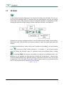
Getting started
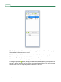
Here you can learn the first steps with SONarchitect ISO. Double-click the icon in your
desktop to run SONarchitect ISO.
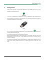
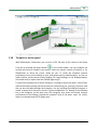
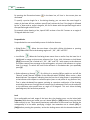
If you have a Professional or Educational version of SONarchitect ISO, ensure that the
security hardlock is connected to a USB port of your PC. If you have the Demo version you do
not need the hardlock to run the program.
Hardlock
You can check the Help Manual by pressing the F1 key or the Help button
find some additional information.
, and you will
Let us help you create your first SONarchitect ISO project.
After launching SONarchitect ISO press New project in the toolbar. You may notice that
SONarchitect has not a menu bar. All the SONarchitect functions are accessed via the
buttons in the toolbar.
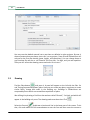
Let us draw our first building. Insert some information in the New Project dialog box such as
project name, Building Code requirements or the default materials for roofs, floors, and
walls.
© 2012 Sound of Numbers S.L.
10
User Manual
You may save the default material set to use them as defaults in other projects. By now it
does not matter what you choose since this is a toy project. Press OK and SONarchitect will
ask you for the first plan details (name, height, and repetitions). You can change these at
any time later. By now let us call "General" the first plan, 3 m high, and just one repetition.
Then you will access the drawing canvas and tools. Let us start!
2.1
Drawing
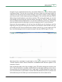
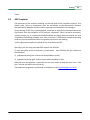
Find the Plans button
and press it. A panel will appear on the left with the Plan list
and Tracing (imported templates) plans. Here you can create new plans, copy them to create
similar floors, change their order in the building, etc. Buildings in SONarchitect are
composed by floors which are created from repetitions of plans.
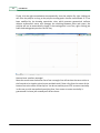
We will begin by drawing a first floor that we have called "General", 3 m high, and which will
appear in the building only once. The drawing mode must be active. Click
Select the Pen tool
and draw an horizontal line in the lower part of the screen. To do
that, click and release the left mouse button to start the line and then move the mouse to
© 2012 Sound of Numbers S.L.
Getting started
11
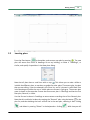
the right. To get a perfectly horizontal line, press Ortho Global tool
or CTRL key while
moving the mouse. The text box at the lower left corner shows the real world length (in
meters) of the line that you are currently drawing. If you want to specify a given length for
your line just write it (the numbers you type will appear in the text box) and press ENTER.
When using only the keyboard, as you have to release CTRL to enter the length, you can lock
the drawing tool by pressing the space bar before releasing the CTRL key. Thus you ensure
that no accidental mouse displacement can spoil the horizontality of the line. Pressing the
space bar again unlocks the drawing, in case you change your mind. Try with 10 meters.
Now move the mouse upwards. You will see that, by default, you are drawing a new line
beginning at the end of the one you just finished. If you would not want another line now,
you would press ESC. But we will draw now a perfect vertical line, so press again the CTRL
key. Lock the drawing tool with the space bar, type 5 and press ENTER to get a 5 m line.
We want to close a rectangle in a right angle, so click
or press the “X” key to enable
“Normal” detection. When “Normal” detection is enabled the label "Normal" appears in the
status bar. Check it.
Now, to draw the upper side of the rectangle, press CTRL while moving your mouse to the
left. If “Normal” detection is enabled, a dashed blue line will appear when you come close to
the zone where the line should end to form a right angle. The blue dashed line means that
your line would end at a point where a normal (the blue dashed line) from a previous line
end would meet your line. When you see the blue dashed line click to draw the line.
© 2012 Sound of Numbers S.L.
12
User Manual
Finally, click the right mouse button to automatically close the polyline. By right clicking you
will close the polyline as long as the polyline starting point remains unconnected. If it has
been modified by the drawing supervision rules, which prevents geometrical artifacts
without architectural sense, and manages the matching between plans and rooms, the
polyline will not be automatically closed. If the starting point is not free, right clicking just
ends the drawing pretty much as the ESC key.
Now we have a perfect rectangle!
Move the mouse over the bottom line of our rectangle. You will see that the cursor sticks to
the line and to its singular points (center and both ends). Draw a line from the center of the
bottom line to the center of the top line. You do not need to press CTRL to ensure verticality
in this case, as with two perfectly matching lines, from center to center verticality is
guaranteed. You have just created you first two rooms.
© 2012 Sound of Numbers S.L.
Getting started
2.2
13
Inserting plans
Press the Plans button
in the toolbar, and create a new plan by pressing
. The new
plan will source four floors of dwellings of our toy building, so name it “Dwellings”, or
similar, and specify 4 repetitions in the New plant dialog.
Note that all plans have a small icon with an eye . This allows you to make visible or
invisible the different plans, to use them as guides for other plans. The current plan, the plan
that you are editing, is the one selected in the Plans list, and it is shown in solid black lines
in the drawing area, while the rest of visible plans are shown in light gray. The current plan
name is shown in the status bar. Ensure that the current plan is Dwellings and that the first
floor plan, General, is visible.
Use the Pen tool to draw in Dwellings an outer contour matching that of the General plan.
Note that this could also be done by copying the “General” plan using the button
in the
plan list, and then deleting the inner vertical line in the new plan, selecting it after clicking
and delete it pressing "Delete" in the keyboard or clicking
. With time you will
© 2012 Sound of Numbers S.L.
14
User Manual
learn all the tricks that will allow you to work with SONarchitect at cheetah speed. But for
the moment, let us continue at snail pace.
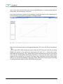
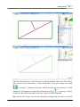
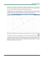
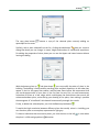
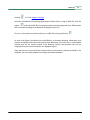
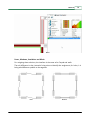
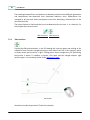
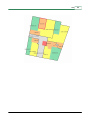
Once you have the outer contour of the building in Dwellings, draw an inner separating line
from one corner to the opposite as shown in the figure below.
Now click on the center point of the diagonal separator. This time click Ortho Local button
or press SHIFT while moving the mouse. With the SHIFT key you force the line being
drawn to be normal to the line at the starting point (if any). It is a “local ortho” mode.
Remember that by pressing CTRL (“global ortho”) you force horizontal or vertical lines (press
CTRL and see the difference). Now using SHIFT draw a line from the center point of the
diagonal line to the top line, as shown in the figure. Now Dwellings has three rooms! Note
that you can see the General plan in light gray, which allows you to ensure proper matching
of elements between adjacent floors with different floor plans.
© 2012 Sound of Numbers S.L.
Getting started
15
Now let us create the last plan, the attic, different from the dwellings plan. This time we will
do it faster. Open the Plans list by pressing
button. Select the dwellings plan and copy
it by pressing
. A new plan appears in the plans list ,with the same name with an
apostrophe added at the end. Double click on the new plan and change its name to "Attic" or
the like. Change the repetitions number to 1.
Press OK to go back to the plans list. Now press the small button with an upwards arrow
to move the new plan to the top of the list, above the dwellings plan. The order of the floors
in the building is given by the order in the plans list. You can change it at any moment as
well as the repetitions of each plan, but it is a good advice that you draw your plans in the
order they will appear in the building, to ensure proper matching between corresponding
elements in adjacent floors with different floor plans.
At some point, SONarchitect will ask you to save the project. SONarchitect does not feel at
ease if you have not saved your project for a while since you started. Once you have saved it
the first time, for your safety, a backup copy of your project will be automatically saved
every few minutes with “.bup” extension. You can see it in your working directory. However,
© 2012 Sound of Numbers S.L.
16
User Manual
do not rely on the backup mechanism to protect your work. Remember to save your project
from time to time, and it is always safer, in big projects, to save new versions of your project
with different file names as you progress. Save your project with the name "Toy project" or
something similar. The drawing canvas will resize from the initial default dimensions to your
current building dimensions.
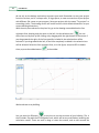
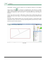
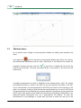
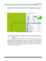
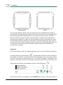
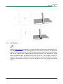
With the attic plan selected in the plans list, go to the drawing area and delete the four
rightmost lines, keeping only the room on the left. Use the selection tool
. You can
select lines one by one, by left-clicking or by dragging with the right button of the mouse. If
you drag towards the right, all the lines partially included in the selection box will be
selected. If you drag towards the left, all the lines completely included in the selection box
will be selected. Select the four rightmost lines, as in the figure, and press DEL to delete
them, or press the rubber button
in the toolbar.
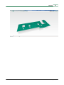
We have drawn a toy building.
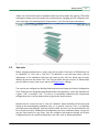
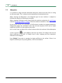
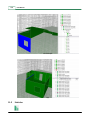
You can press the 3D button
at any time to see the structure of your building. This is
the 3D mode. Play with the 3D navigation tools, which will be very useful when browsing the
calculation results. There are tools to drag or rotate the camera, and to orbit around the
© 2012 Sound of Numbers S.L.
Getting started
17
model. You can move forwards or backwards with the mouse wheel. By pressing CTRL while
moving your mouse, you can translate the camera without changing your 3D navigation tool.
If you lose sight of the building while flying around it, just click the restore view button.
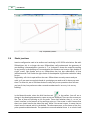
2.3
Use units
Before assigning materials let us assign uses and use units. Each room in SONarchitect has
an “Identifier”, a “Use” and a “Use unit”. The Identifier is just the room name, with no
implications in the calculation, that you may chose at your will, but allows you to better
identify the rooms in the results. The “Use” let you define the type of room. In SONarchitect
you can define as many uses as you want in the Requirement settings.
The uses let you configure any Building Code requirements through the Project Configuration
Form. There you can change the required parameters and quantities, which are defined from
a given “Use” to another “Use”. Do not try to completely understand the requirement
configuration now. It will be clearer when we get to the results section.
Besides the Use, a room has also a “Use unit” identifier, which identifies all the rooms that
belong to the same dwelling, habitation unit, or, in general, Use unit. Thus, in a dwelling,
you have rooms with different Uses but with the same Use unit. The Use unit identifier can
be as simple as a letter. SONarchitect distinguishes Use units in different floors, so you can
use the same letters for any floors. You can configure this behavior through the Project
Configuration form, for specific multiple floor Use units, such as duplex apartments.
© 2012 Sound of Numbers S.L.
18
User Manual
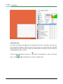
Let us assign uses to our toy building. Press
is the Type/Units mode.
and a panel will appear on the right. This
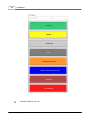
This could be an example of Uses definition.
Select the first plan, General, in the plans list. By right-clicking and dragging select both
rooms. You can also do multiselection by picking while holding SHIFT. Assign a use,
otherwise it will appear in light grey. Assign Common use. By selecting the rooms one at a
time, assign a suitable identifier in the Enclosure identifier text box, such as "Entrance", for
instance. Notice that the identifier is shown inside the rooms. Common area rooms do not
need use unit identifier. By default they are always different from any other use unit,
although you can modify this behavior through the Project Configuration form.
© 2012 Sound of Numbers S.L.
Getting started
19
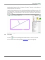
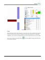
Go now to the dwellings plan. Select the biggest room (right bottom one) and assign a
Protected use by clicking the Protected button. The room color changes to green, which is
the color of protected rooms, as you can see in the corresponding button. As identifier you
may write something like "Bedroom". Now select the left room and assign a Habitable use.
The color should change to yellow. As identifier you may write something like "Bathroom".
Select both rooms and specify use unit "A", by typing A in the Use unit text box. The “A”
letter appears, in brackets, next to each room identifier and the line between the rooms is
now thinner, as they belong to the same use unit. Finally, select the third room and assign to
it a Stairs use. Its color should change to dark gray. Name it "Stairs", or similar. The result
should look like the figure below.
© 2012 Sound of Numbers S.L.
20
User Manual
Go to the room in the “Attic” plan. Assign it a Protected use and name it "Bedroom". Use “A”
as unit identifier.
© 2012 Sound of Numbers S.L.
Getting started
2.4
21
Slabs
It is time to specify the materials. Go back to the dwellings plan. Press the "Materials mode
button"
and the Materials Catalog will be shown. There you can select and assign all
the materials for your building elements and linings.
First we will select "Slab" in the first material list. The rooms color will change to the color of
the default slab solution you chose at the beginning of the project. Move the mouse over the
rooms and you will see the material name in the status bar. If you want to change the slab
material select the room or rooms, locate the material in the catalog and press the "Assign"
button. The configurable colors in the material list provide visual feedback in the modified
slabs.
For the "Stairs" enclosure we are going to manage a slightly more refined situation. Let us
imagine that we have a lightweight stair in the room, such that the enclosure is connected
from floor to floor. It is a unique enclosure 18 m high. To get it we just need to select the
"Stairs" room and click the Virtual2D button
or press the "V" key (“V” for Virtual). Thus
you virtualize the inner slabs in a series of repetitions, i.e. you remove them from the
building, connecting adjacent volumes between floors stemming from repetitions of the
given plan.
Note that, by using the Vritual2D button or the “V” key, you virtualize the slabs only between
plan repetitions. For other slabs, you must use the corresponding tool in the 3D view of the
building.
© 2012 Sound of Numbers S.L.
22
User Manual
Thus, for instance, if you want to design an inner courtyard, you also need to virtualize the
roof in the last floor repetition, and you must use the 3D virtualization tool
in the 3D
mode
. You also need this tool to virtualize any slabs between adjacent floors with
different plans.
2.5
Walls
Select now Walls in the material list. The plan scheme changes to show the vertical
elements of the building, in the color of the corresponding default solution you have chosen
at the beginning of the project. Now select Wall lining. The representation changes to show
the wall linings of the building. When in light gray, no linings have been assigned yet. You
may want to assign some or change the walls materials. To do that, just select the walls or
linings, browse the catalog and press “Assign”. Browse the different Subtypes and Catalogs
through the lists in the Right Panel. If you are using the Demo version you will see only a few
materials available, but enough to play with the toy building.
© 2012 Sound of Numbers S.L.
Getting started
23
There are some shortcuts to ease the task of assigning materials. When you click inside a
room, all the walls are selected or, if in Wall lining mode, all the inner linings. By clicking
or pressing "F" (façade) all the outer walls of the plan will be selected. If in Wall
lining mode, all façade inner linings will be selected. By clicking
or pressing "I" (inner)
all the inner walls will be selected, or the inner linings if in Wall lining mode.
When all the wall linings of a room are selected (by clicking inside the room in the wall
© 2012 Sound of Numbers S.L.
24
User Manual
lining mode), a common area for instance, you can change the selection to the neighbor
linings just by clicking
or pressing "C" (complementary). This way you can quickly
assign a common solution to every inner lining of all rooms adjacent to a common area,
which, for our experience, saves a lot of time. “C” also works when only a few linings are
selected.
Finally, if you select some walls, in Wall mode, and then switch to Wall linings mode, the
selection will carry to the linings, i.e. all the linings of the previously selected walls will be
selected.
Remember that for multiple selection you can use SHIFT and pick, or drag with the right
mouse button, either to the left or to the right, depending whether you want strictly inclusive
selection or partial inclusive selection.
F key - Façade
© 2012 Sound of Numbers S.L.
Getting started
25
I key - Interior walls
Room selection
© 2012 Sound of Numbers S.L.
26
User Manual
C key - Complementary selection
2.6
Elastic junctions
Junction configuration used to be tedious and confusing in ISO 12354 calculations. But with
SONarchitect this is no longer the case. SONarchitect really understands the geometry of
your building. It knows whether a junction is T- or X-shaped. It knows the materials meeting
at any junction in the building so it knows whether the elements are heavy or light, double or
single, massif, light façade, and so on. SONarchitect has, but also understands, all that
information and it will make the right choice of the adequate Kij (vibration reduction index)
for you.
Regrettably, still a bit is required from the user. SONarchitect currently cannot read you
mind, so if you want to use elastic bands in your design you need to tell it where you want
them. To solve this, we at SON have devised a really easy-to-use procedure that will save
you lots of time, but you have to take a second to understand it. Let us try it in our toy
building!
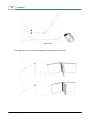
In the Materials mode, select the Wall Junction tool
in the toolbar. You will see a
change in the drawing representation; some arrows are displayed. There are four arrows per
line. Two of them are pointing to the line ends. These mark whether there is, or not, an
elastic interface in the extreme of the wall they point to. If the arrow is solid it means that
there is an elastic band in that side of the wall, whilst if the arrow is open, it means that no
elastic band is inserted, which is the default. The other two arrows, at the center of the line,
point upwards and downwards. The upwards arrow marks whether there is an elastic band
© 2012 Sound of Numbers S.L.
Getting started
27
between the wall and the ceiling (hence up), whilst the downwards arrow marks whether
there is an elastic band between the wall and the floor (guess what?). To change the arrows
state, just click inside them. They will switch between solid and open.
In bigger plans than our toy building you may need to use the mouse wheel to zoom and
move around the plan. Note that zooming in is always focused at the cursor, whereas
zooming out centers the drawing. Hold CTRL and drag to move the drawing area.
You may also need to insert elastic junctions into the slab, which is of great use to model
the dilation joints common in large buildings. To do that, select the Slab Junctions tool
. You will see that arrows appear inside the contour of each room, pointing towards it. They
mark whether there is, or not, an elastic interface between the slab and the wall they are
pointing to. As before, with Wall junctions, solid arrow means that there is an elastic
interface, while open means there is not.
© 2012 Sound of Numbers S.L.
28
2.7
User Manual
Windows, doors...
Let us provide some sunlight to the prospective dwellers by adding some windows and
doors.
Press again the
button in the tool bar, browsing the Window type. Select, for instance,
the wall between the bedroom and the stairs. Select Door in the material list, browse the
catalog for the door you want, and click
or press Enter. A dialog will ask you for the
surface area of the door. Of course, you should insert an area which is less than the wall
surface area.
A symbolic representation of a door is displayed in the selected wall or walls. The symbol
just indicates that there is a door in the wall, not the exact position of the door in the wall,
nor its characteristics. For the computation of ISO 12354, the location of the openings in the
walls is not relevant. So keep in mind that the doors and windows you can see in the 2D and
3D representations of your buildings are just mere indicators of presence. Do not expect that
the 3D view of the façade of your model will look like the real building. SONarchitect is an
advanced acoustic computation tool, not a photorealistic 3D renderer. To check the
characteristics of any openings in a given wall, you have to select the wall, go to the
© 2012 Sound of Numbers S.L.
Getting started
29
openings tab and inspect the list at the bottom of the panel. There you can also delete any
unwanted windows, ducts and doors.
It may be of great convenience to insert a door between Bedroom and Bathroom to get relief
in critical moments. Try also to put some windows and ventilation ducts. Notice that you can
insert windows in all façade elements in one strike just by selecting all façade elements
with the “F” key.
2.8
Let's rock!
Just press
and our toy building project would be solved in a fraction of a second.
Let's see all the results in that toy building (requirements have to be configured):
© 2012 Sound of Numbers S.L.
30
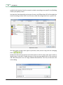
User Manual
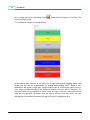
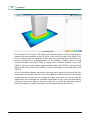
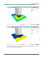
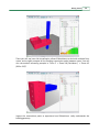
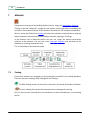
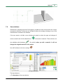
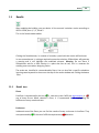
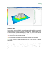
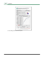
Total building emission
On the left part of the screen a 3D model of the building appears, currently displaying the
outdoor noise map calculation as per ISO 12354-4. The tree on the right is the Results Tree.
This is no ordinary tree, but a powerful analysis tool. You can browse every detail about the
acoustic performance or underperformance of the building, including airborne sound
insulation between rooms (ISO 12354-1), impact sound insulation between rooms (ISO
12354-2), airborne sound insulation against outdoor sound (ISO 12354-3), transmission of
indoor sound to the outside (ISO 12354-4), and sound absorption in enclosed spaces (ISO
12354-6).
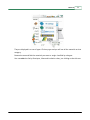
At first, SONarchitect displays the outdoor noise map, which appears at the top of the tree,
resulting from the sound transmission of all rooms defined as noisy enclosures in the Project
Configuration Form, where you can change the indoor noise level of any room and the
requirements. You can browse the individual contributions of every room and separator by
clicking the results tree. When an element contribution is clicked, the equivalent acoustic
power of the element LW[dB] is displayed in the bar graph below the Results Tree.
© 2012 Sound of Numbers S.L.
Getting started
31
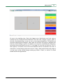
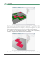
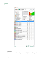
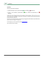
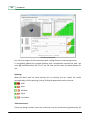
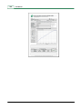
Room emission
Wall emission
Now click the Floor nodes in the Results Tree (let's take a bigger real building, so we can
show you all the different topologies clearer).
© 2012 Sound of Numbers S.L.
32
User Manual
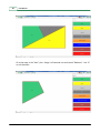
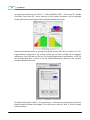
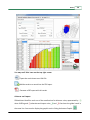
All rooms in floor 0 are displayed. The horizontal elements of the floor are shown in red or
green. Rooms in green meet all the requirements, while rooms in red fail one or more
requirements. The requirements are configured in the Project Configuration Form, with
different requirements depending on the uses of the receiving and transmitting rooms.
Let us click the first room displayed under floor 0, which is Room 3 (Distributor),
“Distributor” being the identifier chosen for the room by the designer.
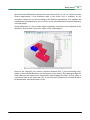
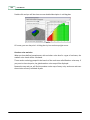
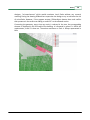
The distributor is displayed. Here you have a good example of the kind of arbitrary
© 2012 Sound of Numbers S.L.
Getting started
33
geometries that SONarchitect tackles with ease. Notice that it is red, as it does not meet
several requirements. If the Distributor node in the Result Tree is unfolded, all the
calculation results can be seen according to the different requirements. First appears the
reverberation time requirement; you can click it to see the reverberation time with frequency
in the bar graphs.
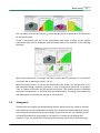
Further down there is a set of nodes with the insulation results from rooms adjacent to the
distributor. Click on node “from room 2 (Box 2 0ºD)” and expand it.
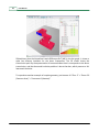
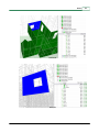
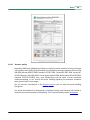
Now you are displaying the acoustic insulation between Box 2 (the transmitting room,
always in blue) and the distributor (receiving room, red or green). By browsing through the
child nodes you can inspect every transmission path between the rooms. At first glance a
transmission path in red stands out. This is the result that SONarchitect has determined to
be the dominant transmission path. Click it.
© 2012 Sound of Numbers S.L.
34
User Manual
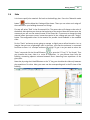
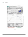
SONarchitect plots the Normalized Levels Difference DnT [dB] in the bar graph. It shows a
quite low airborne insulation for the lower frequencies. The 3D model shows the
transmission path. By the representation it becomes evident that it corresponds to the direct
transmission, and that the sound insulation problem is due to the door, which presents a fair
low sound insulation.
To experience another example of complex geometry just browse till “Floor 2” > “Room 30
(Common Area)” > “from room 9 (elevator)”.
© 2012 Sound of Numbers S.L.
Getting started
35
There you will see how slab virtualization allows SONarchitect to deal with multiple floor
rooms, and to rightly compute all the flanking transmission paths between rooms. You will
also see another interesting example in “Floor 0” > “Room 18 (Distributor)” > “Room 45
(Office 3ºG)”
Inspect the transmission paths to experience how SONarchitect really understands the
building geometry.
© 2012 Sound of Numbers S.L.
36
User Manual
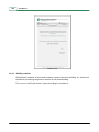
Let us go forth. Browse for the “Floor 3” > “Room 38 (Office 3ºB)” > “from room 39”. Double
click node “from room 39”, and a summary of the acoustic insulation will be displayed
showing the airborne and impact sound insulation between the rooms.
Notice that some information is missing in the Demo version (all in all it is a demo, isn’t it?).
It goes without saying that a full license entitles you to have all fields full of insightful
information. If you click the tiny file icon in the top right corner of the summary, a PDF file
will be generated with a record of all the needed information related to the acoustic
insulation between the room.
By double clicking node “Wall 1” (or by selecting it in the summary combo box) an airborne
sound insulation summary will appear. The same occurs with the “Slab 1” and the impact
sound insulation.
© 2012 Sound of Numbers S.L.
Getting started
You can always click the tiny file icon
of the specific result.
37
in the top right corner to generate a PDF document
Finally, if you double click one of the transmission path nodes, a report of the specific
transmission path will be displayed, with information about the materials of the flanking
elements.
Again some information is missing in the Demo version and PDF generation is not allowed.
Do not you feel as wanting a license? Call us!
With the licensed version, if you are not satisfied with the results, you just go back to 2D,
and change the design, materials, junctions, or uses as many times and as far as you want.
Then, in a matter of seconds, you will get the new results. This iterative process, unfeasible
with most of applications, is fast and easy with SONarchitect, increasing your productivity
and allowing you to optimize your designs in practical time.
2.9
Histograms?
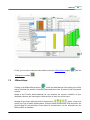
SONarchitect can compute the whole building acoustic performance in a matter of seconds,
and it allows you to see and browse the results in an intuitive and comfortable way, letting
you to improve and optimize the acoustic design of your projects. But, can it do even more?
In Sound Of Numbers we love numbers, and statistics is a smart way of dealing with
numbers. In fact, the whole ISO 12354 computation process comes from Statistical Energy
© 2012 Sound of Numbers S.L.
38
User Manual
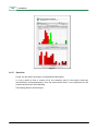
Analysis. What about performing statistics with the statistics? What if we compute the
statistics of the acoustic insulation of the entire building? Could we estimate the probability
distribution of the acoustic insulation?
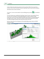
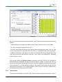
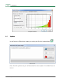
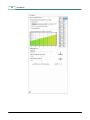
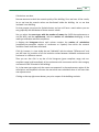
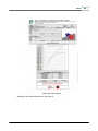
Yes, we can. You can see the statistics of your building just by pressing
toolbar.
in the Results
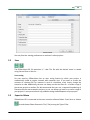
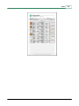
The matrix shows every combination of pairings of types of rooms in the building. Clicking
any matrix cell will show the corresponding histogram of acoustic insulation results.
Furthermore, you can click any histogram bar and all rooms within the corresponding levels
will appear in the 3D view. Thus you can localize and also visually inspect the set of the
worst/best/average/in-between performing rooms quickly and easily.
But let us show some of the histograms of real-sized building projects with over 30,000
calculation results.
© 2012 Sound of Numbers S.L.
Getting started
2.10
39
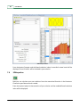
To report or not to report!
With SONarchitect Professional, you can print a PDF file with all the results in the Result
Tree just by pressing the Report button
in the results toolbar. You can configure the
sections you want to include in your report, select the acoustic records of interest, or let
SONarchitect to chose the critical results for you. To justify the complete acoustic
performance of an entire building to your local government or administration, you do not
need to deliver all the records of your building. For large buildings as the displayed above,
this would result in reports well over 30,000 pages long!!.
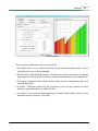
To justify the compliance of an entire building it is enough to report the worst case records,
and the information proving that the records you are delivering are, precisely, the worst. And
that can be easily done through the histogram. Just by including the building histogram, a
record is shown to be the worst case for a given configuration if it belongs to the extreme
bar in the histogram. At the same time, the histogram also shows the overall acoustic
performance of the building, beyond the insulation level of the worst cases. So, luckily,
reports can be kept about 20-30 pages long!
© 2012 Sound of Numbers S.L.
Chapter
III
File
File
3
41
File
After starting SONarchitect, you can open a previous project or start a new one. In the
toolbar you have the New and Open buttons.
SONarchitect ISO file type is *.SDW
3.1
New
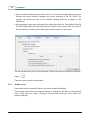
Pressing the New button on the toolbar, you start a new project.
The dialog "Project Properties" allows you to enter information necessary to start with your
project.
On the first tab, "Project", SONarchitect asks you to enter information identifying the project
and the name or reference. Both the Software licence owner and the organization are given
by your license SONarchitect.
In case someone else in your company is using SONarchitect you can specify an Author
name.
Insert a Project title and a reference that will be included in the PDF report. Also the Author
name and the Organisation will be included.
You may optionally define an initial drawing area, by specifying the X and Y spans in meters,
to better adapt the drawing area to your project since the beginning. In any case, the
drawing area will be automatically adapted to your drawing anytime you save your project,
and it grows on demand while you draw.
Now you have four considerations for the calculations:
· Consider different unit for rooms on different floors: If you check this point adjacent rooms
located in different floors will be considered as different units. See requirements section.
· Do not compute outdoor map: Disables the visualization of the outdoor noise map.
© 2012 Sound of Numbers S.L.
42
User Manual
· Do not consider flanking elements minor than X m: Very small flanking elements can over
estimate the sound insulation between two rooms according to EN ISO 12354. The
engineer can decide the area of the smallest flanking elements to appear in the
calculations.
· Do not compute impact sound insulation from slabs minor than X m: The method of the EN
ISO 12354 might under estimate impact sound insulation for very small slabs. You can limit
the calculation for avoiding small slabs impact sound insulation in the results.
You can edit the data in the "Project Properties" dialog at any time by clicking the Properties
button
.
There are 4 other tabs for entering data:
3.1.1
Outdoor noise
Data related to environmental incident noise levels outside the building:
Diurnal noise index of the most exposed façade as reflected in the map of environmental
noise. Failing that, but having a zoning of environmental sound, you must specify the
acoustic area type.
© 2012 Sound of Numbers S.L.
File
43
Outdoor noise
So, you can choose the default incident outdoor noise levels by choosing among these three
options:
- Predefined spectrum shape noise: White, Pink or Brown. Define the level L1,2m [dBA].
- The level according to the placement area.
- A custom level, defined by the user just inserting the one-third octave values. You can save
or load a custom level in one third octave. The file is a *.sns (SONarchitect Noise Spectrum)
In addition, specify the noise index Ld for roofs in the Roof tab next to the Façade tab, in the
same way than the Façade incident noise but it also allows the disabling for calculating
airborne noise in roofs.
You can also choose the diffusion factor: According to the UNE 12354-4, Cd is defined as
the level difference between the acoustic pressure level in a point, 1 or 2 m away from the
the interior face of the façade, and the intensity level that comes perpendiculary into contact
with that element. It is influenced by the diffusion of the sound field inside the room and the
absorption of the interior of the façade segment. Those 5 options you have in SONarchitect
are contained in the Annex B of the 12354-4.
3.1.2
Requirements
SONarchitect ISO follows the ISO EN 12354, with no specific legislation directives. You can
© 2012 Sound of Numbers S.L.
44
User Manual
establish and customize limits for acoustic insulation according to any specific local Building
Code or your quality criteria.
Just input the limits depending on the type of rooms, and SONarchitect ISO will threshold the
results according to those limits. You can save or load this configuration from a specific file.
Requirements creation
You must create as many room types as you need, erase, move or copy with the managing
tools:
.
Double click the room type and you must also choose a color for every room type in order to
identify them in the plan. Change the name of the room type double click on the name and
add a brief description. You can assign a Medium Reverberation Time Tm,f to that room also
in that dialog.
© 2012 Sound of Numbers S.L.
File
45
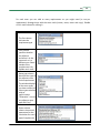
For each room you can add as many requirements as you might need (a row per
requirement). Manage them with the same tools (create, erase, move and copy). Double
click in each column for editing it.
The first column
indicates the
requirement type
From column
specifies whether
the adjacent
enclosure is in the
same unit or in a
different one. Select
outdoor if the
requirement is for
façades and roofs.
Room type column
identifies the type of
the adjacent room
for the requirement.
The window displays
all the room types
you have created, all
other types selection
with no
speficications
"Otherwise", or even
any adjacent room
type with "Any"
Param column
selects the acoustic
parameters for the
calculation for every
type of requirement.
© 2012 Sound of Numbers S.L.
46
User Manual
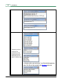
Frequency column
contains the
evaluation of the
frequency domain
depending on the
type of requirement.
In Custom noise, you can load a *.sns file with the spectrum
data. This file can be created in the Outdoor noise tab.
© 2012 Sound of Numbers S.L.
File
The sixth column
displays the
comparison operator
for each type of
requirement.
47
= For airborne noise insulation.
= For impact noise insulation and reverberation time
= For Level indoor noise
Threshold value
Modifier: Choose the
direction of the
calculation
(horizontal, vertical
or both)
3.1.3
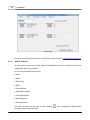
Classification schemes
SONarchitect has included nine schemes of acoustic quality classification. Choose the
country and you will assign the range values for airborne and impact sound insulation
between different units and within the same dwelling.
© 2012 Sound of Numbers S.L.
48
User Manual
Schemes dialog
Once you have selected the scheme, the PDF report will contain the classification statement.
3.1.4
Default materials
As most projects use mainly a small subset of building solutions, you can define some to be
assigned by default as you draw.
You can specify default solutions for:
· Slabs
· Walls
· Wall lining
· Roofs
· Floating floors
· Suspended ceilings
· Ceiling absorption
· Wall absorption
· Floor absorption
Just click the button to the right of each category
catalog of constructive elements:
© 2012 Sound of Numbers S.L.
, thus accessing the SONarchitect
File
49
Default materials
You may Save the starting preferences to use them in other projects.
3.2
Save
The SONarchitect ISO file extension is *. sdw. The file with the desired name is created
using the tool Save or Save As ... .
Auto saving
For your security, SONarchitect has an auto saving feature by which your project is
automatically saved at regular intervals with extension .bup. If you want to access the
contents of a backup file, for instance in case of a hardware crash, simply change the
extension to .sdw. Additionally, the user can always use the tool Save As .. to make a copy of
the current project to another file. We recommend that you use a sequential numbering of
filenames for your more complex projects, so you can always go back to an earlier stage of
your project in case you encounter any problems during the development of your project.
3.3
Export to Odeon
SONarchitect ISO is connected to the room acoustics software Odeon. Press Save as.. button
as and choose Odeon Parametric File (*.Par) among the Type of files.
© 2012 Sound of Numbers S.L.
50
User Manual
Then you will be able to load the SONarchitect ISO 3D model of the building in Odeon.
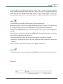
3.4
Open
With the Open button you can load an SDW file.
For better accessibility, the arrow on the right displays a list of recent projects.
© 2012 Sound of Numbers S.L.
Chapter
IV
Program settings
52
4
User Manual
Program settings
SONarchitect computes sound insulation according to EN ISO 12354. It must be fed with
some user data:
· Geometry
· Materials
· Uses
· Atmospheric conditions
The geometry is input in the drawing stage but the user can configure SONarchitect where
the materials, uses and atmospheric conditions come from. This will be the default
configuration.
In addition, you will have your SONarchitect licence always up to date using the Updates
application.
4.1
Options
Click the Program Settings button
(little button near the status bar).
· When you have previously created your limits, load a *.lim file that may contain your
desired requirements:
© 2012 Sound of Numbers S.L.
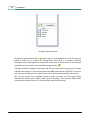
Program settings
53
Load requirements file
· Decide where the database is located. Choose whether the database is a Local User Data
Base or it belongs to a SQL server. Just enter the connection data for accessing the
Remote SQL Data Base and click Connect. See the SQL Server Quick Install Guide.
Database locator
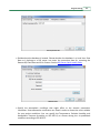
· Specify the atmospheric conditions that might affect to the acoustic parameters
calculation. Some attenuation coefficients are listed in order to choose the most suitable
for your project conditions. You can specify the Temperature, Relative Humidity and
Atmospheric Pressure (according to ISO 9613-1) or choose among the six predefined
conditions according to ISO 9613-2.
© 2012 Sound of Numbers S.L.
54
User Manual
Atmospheric conditions
4.2
Updates
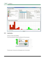
You will access to SONarchitect updates just clicking the Check for Updates Button:
Update window
Click Check for updates and you will download the latest update if available from our
servers.
© 2012 Sound of Numbers S.L.
Chapter
V
Working modes
56
5
User Manual
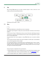
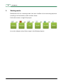
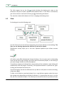
Working modes
SONarchitect ISO has six working modes. We have classified all the tools and group them
according to its functionality in order to make it faster.
Each mode concerns a stage of the project.
Let us take a deeper study of these stages in the following chapters.
© 2012 Sound of Numbers S.L.
Chapter
VI
Drawing
58
6
User Manual
Drawing
After setting up the project, you can proceed to create the different floors. This is the first
stage: the drawing mode.
In SONarchitect a building consists of plans and floors. A plan is each of the different floor
plans, which, by repetition, lead to the different floors of the building. This makes it possible
to build a 10-floor building from, for example, 3 plans: ground floor plan, present only once,
becomes floor 0, a dwellings plan, repeated 8 times, giving floors 1 to 8, and an attic plan,
present only once, becoming floor 9. In the Professional version of SONarchitect a building
can have as many different plans and as many repetitions as needed. The distinction
between plans and floors allows not having to draw and manage as many plans as floors has
the building.
SONarchitect allows the import of a DXF file as a template to draw plans from a CAD project.
An intelligent cleaning of the DXF file before using it as a template is recommended, to
improve its value as a template for drawing and to reduce the likelihood of operator errors.
Note that the acoustic calculation as per the ISO standard requires a simple model of the
building, to ensure the acoustic significance of the results. You can also use plans imported
from other SONarchitect projects as templates for your project.
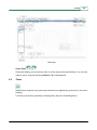
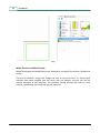
The figure below shows SONarchitect’s initial screen.
© 2012 Sound of Numbers S.L.
Drawing
59
Initial desktop
Undo / Redo
During the drawing, you can undo or redo an action by pressing these buttons. You can also
undo an action using the command [Control + Z] on the keyboard.
6.1
Floors
SONarchitect computes every encounter between two neighbouring enclosures in the entire
building.
To do this, you have the possibility of drawing floor plans for the building floors.
© 2012 Sound of Numbers S.L.
60
User Manual
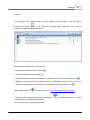
Plan List
The Plan list contains all the necessary tools to manage the plans and floors of your project.
You can place it wherever you may need.
To hide the tab, just click the button Plan list again or in the X button in the top right corner.
To draw in a given plan just select it in the list. Its name appears in the status bar.
You can create a new plan and edit, copy or delete the current plan:
Clicking on new plant
opens a dialog box where you can edit the name of the plant to be
set up as well as its height and the number of consecutive repetitions of the plant to make
way for floors. You can change any of these securities at any time.
© 2012 Sound of Numbers S.L.
Drawing
61
New plan
The copy plant button
apostrophe to the name.
creates a copy of the selected plant currently adding an
Similarly, with a plant selected from the list, clicking the edit button
plant you access a
dialog box where you can change its name, height and number of consecutive repetitions.
For editing the properties of other plants you can use the Upper and Lower buttons without
leaving the dialog.
Edit plan
With the buttons plant up
and plant down
you can modify the order of plant in the
building. The building is constructed by stacking plans and their repetitions in the order they
appear in the list: the upper floors above, and the lower floors below. We recommend that
you set the proper order of your plans in the list from the very first, to avoid unnecessary
relocations of plans at a late stage, which could bypass the mechanisms that control the
coherence between plans, active during your drawing of the plans, thus making it possible
the emergence of "microflanks" which would unnecessarily entangle the results.
Finally, to delete the selected plant, just click the Remove plant button
.
To exploit the high correlation between different plans that usually exists in a building, you
can use other plans as a template, represented in light gray.
To show or hide other than the current plants, just click the icon on the left
the plant is visible and grayed out otherwise.
, in color when
© 2012 Sound of Numbers S.L.
62
User Manual
The little magnet icon on the left
controls whether the drawing tool snaps to the
elements of the plan to allow a perfect match between floors. If this effect is not desired,
just click on the icon itself and it will turn gray , deactivating the feature.
The status bar shows which element of a line is trapping the drawing cursor.
6.2
Draw
For drawing we have the following tools:
Use the Draw tool to trace the lines representing the vertical divisions of the building. The
lines you are drawing represent the mid-line of each wall or façade.
SONarchitect actively helps you in this task. Optional keyboard input allows accurate
drawing.
Lines
Left-click or press [L] in the keyboard to begin drawing a line at a given spot in the drawing
area. End the line by right-clicking if you do not want to continue a polyline, or left-clicking if
you want to begin another line from the endpoint.
If a polyline or sequence of chained lines was started at a free nodal point, right-clicking will
automatically close the polygon. Conversely, if the polylines started at a previous-line, rightclicking just terminates the current line.
If you terminated a line with the left button but you did not really want to continue drawing,
simply press [Esc].
To draw a line linked to a previously drawn line, a snap indicator appears under the cursor
that changes color depending on the kind of reference. It is green when the cursor is on the
line, but at no characteristic point. This allows you to be sure that the line you draw will start
© 2012 Sound of Numbers S.L.
Drawing
63
from the original line, effectively dividing the original wall. It changes to orange when the
cursor is above the midpoint of the base line or any of its ends. The snapping mechanism
works also with DXF templates and other plans, as long as the magnet is on for the
corresponding template layer or plan, which appear in a lighter shade under the current plan.
Select
Click this button or press [S] in the keyboard for choosing Select tool.
When we hover over a line, it turns orange, indicating that you can select it. You select lines
by clicking on them, and they turn red. Subsequent clicking deselects selected lines.
Holding down [Control] temporarily activates the Move tool, which allows dragging the
drawing.
Multiselection is possible by holding down [Shift] while clicking. Multiselection can also be
performed by dragging with the right button:
· If you drag from left to right, the lines entirely contained in the box are selected.
· Conversely, if you drag from right to left, lines partially or totally contained in the box are
selected.
Click in any empty region of the drawing or press [Esc] for unselect all.
Delete
To delete the selected segments simply press [Delete] or the Eraser button for that purpose.
Dimensions
Dimensions in the status bar
© 2012 Sound of Numbers S.L.
64
User Manual
By pressing the Dimensions button
annotated.
in the lower bar, all lines in the current plan are
To specify a precise length for a line during drawing, you can enter the exact length in
meters in the lower left box, and then press [Enter] to draw the line. If the length is followed
by the "a" letter and an angle in degrees, the line is drawn with the specified length and at
the specified angle with the X-axis.
For example, when drawing a line, input 4.5a35 to draw a line of 4.5 meters at an angle of
35 degrees with the X-axis.
Perpendicular
Perpendicularities are controlled by means of the Ortho features:
· Global Ortho
: When the user draws a line while clicking this button or pressing
[Ctrl] SONarchitect limits the drawing angles to 0 °, 90 °, 180 ° and 270 °.
· Local Ortho
: When the line being drawn stems from an earlier line, the base line is
highlighted in orange as the current reference line. If you click this button or hold down
[Shift], the current line is limited to 0 °, 90 °, 180 ° and 270 ° with respect to the reference
line. When several lines converge at the starting point, only one is the reference at a given
time (in orange). To switch the local Ortho reference in clockwise order just repeatedly
press [R].
· Ortho reference or Normal
: By clicking it or pressing [X] you switch on and off the
“Normal” mode ("Normal" appears in the status bar when enabled). When active, a blue
dotted indicator line appears indicating that the line that is being drawn is perpendicular
to the indicator with respect to a reference point (start or end points of any previous line).
That is, when the dotted line appears, pointing at a previous nodal point of the drawing,
terminating the current line right there ensures that a subsequent line from the end point
to the reference point would form an angle of 90 degrees. This tool allows drawing
parallelograms, but has further potential.
Lock
For a comfortable and safe usage of the input box, the drawing cursor can be locked with
[Spacebar]. With the cursor locked, you can release [Ctrl] or [Shift] without losing the Ortho
mode currently in use. This prevents involuntary movements of the mouse from spoiling the
orthogonality of a line when specifying a length. Just remember not to release [Ctrl] or
[Shift] before pressing the space bar, so that the locking enters with the intended mode still
© 2012 Sound of Numbers S.L.
Drawing
65
active.
6.3
DXF Templates
The robustness of the acoustic modeling, an inherent need of the calculation method. Thus
double walls, pillars or downspouts must be assimilated to two-dimensional elements
characterized by adequate acoustic values, requiring the intervention of the designer.
Smart cleaning of DXF files is recommended, to remove all superfluous elements without any
significance from the standpoint of ISO acoustic calculation: Plants, furniture, decoration,
symbols, names, etc. It is also recommended to delete the design elements outside the area
occupied by the building (compass rose, scale, frame, etc.). SONarchitect adapts the drawing
surface to the templates when these are greater than the current drawing.
Is also highly recommended to explode all the lines within the DXF.
Specially if you are using some AutoCAD objects like 2DSolids:
1) mark everything and use command _convtosurface
theirs bottom)
(the 2DSolids will get surfaces on
2) _explode everything (the surfaces will be exploded to areas)
3) _explode everything again, and the areas will be exploded to lines.
Note that once the template is imported, the user only needs to draw the basic lines of the
plan, ie those that define the enclosures.
The template management is performed in the bottom of the Plant Management panel.
© 2012 Sound of Numbers S.L.
66
User Manual
Tracing plans section in the Plans tab
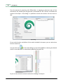
Through the new template button
specific layers can be loaded from a DXF file (click All
button to select all, or unselect all clicking None). Each layer is a template. Different
templates can be used together or separately. If you want to delete some of the imported
templates, you only need to click the delete template button
.
The figure shows the dialog for importing a DXF file that allows choosing the layers to import
and add as templates. It is important to note that SONarchitect works in METERS. To suit this
unit, the import dialog permits to specify the scale of the imported template and the unit.
You can also choose the coordinate system in order to locate the DXF model within
SONarchitect drawing zone. Indeed, when the DXF drawing is not centered SONarchitect
automatically relocate it when it is more than 2km away from the origin.
© 2012 Sound of Numbers S.L.
Drawing
67
DXF import
Templates with the icon
taking of references.
active are appear in light grey in the drawing area, allowing the
The inclusion of a template is functionally analogous to the representation of different plans
under the current plan.
Thus, the Pen tool snaps to the templates. This feature is activated and deactivated by the
magnet icon to the left of each template in the list. The status bar indicates the kind of snap
in action. Ortho and Normals also work with active templates.
6.4
Zoom
The Zoom permits pan and zoom the view of the current plane, in both 2D and 3D.
Additionally, for convenience, you can increase or decrease the zoom using the mouse
wheel.
Scroll wheel zoom
© 2012 Sound of Numbers S.L.
68
User Manual
To retrieve the overview of the building, both 2D and 3D, there is also the Fit to window tool,
.
The 2D zoom percentage is indicated at all times in SONarchitect status bar, so you have a
better location of the project.
Zoom in the status bar
Move
In 2D mode, you can move around the plan by clicking anywhere on the desktop and
dragging as long as the Move button on the toolbar is activated. Alternatively, to allow
moving the plan without releasing the current tool, you can temporary enter Move mode by
holding down [Ctrl], or even holding down the center button of the Mouse.
Additionally you can use the Keyboard [arrows]
drawing and moving.
© 2012 Sound of Numbers S.L.
, thereby facilitating simultaneous
Chapter
VII
Materials
70
7
User Manual
Materials
The geometric structure of the building defined, we can assign the constructive solutions.
Clicking on the tool "Materials" a range of tools appears on the right side for managing the
inclusion in the model building of all the elements necessary for the insulation computation.
We can access the SONarchitect catalog of constructive solutions to identify those materials
that correspond to each element of the building: materials, openings, finishings...
In the Solutions tab in Materials section the user can assign the desired constructive
solutions to the elements. You can also create your own solutions and add them to the
database by inserting the required data.
This is the toolbar of the Materials mode:
7.1
Catalog
Constructive solutions are assigned just by browsing the materials in the catalog database.
There are two main catalogs: SON Catalog and User Catalog.
The SON Catalog contains all the built in materials in the Sound of Numbers Database.
The User Catalog will contain the materials you are creating and inserting.
You can also view the materials from the databases of several manufaturers just browsing
the list:
© 2012 Sound of Numbers S.L.
Materials
71
They are displayed in a tree of types. Click any type and you will see all the materials on that
category.
Browse the tree and find the materials you want to assign classified by subtypes.
You can order the list by Descriptor, Mass and Insulation value, just clicking on the title row.
© 2012 Sound of Numbers S.L.
72
User Manual
Browse the
You can even connect this catalog to a remote SQL database. Configure the conection
© 2012 Sound of Numbers S.L.
Materials
clicking
73
or in the Program settings.
You have the posibility of importing big ammount of data, batch, using an XML file: click the
button
and load a XML file from your computer previously exported from SONarchitect
ISO or created according to the Material Exchange Format v2.0.
Or you can also export a material solution to a XML file pressing the button
As seen in the figure, the solutions are identified by a schematic drawing, a descriptor, and
acoustic and physical data that characterize them. Moreover, each color has a customizable
solution that can be visually located in the drawing. Initially, the elements that are not
assigned to any constructive solution are displayed in grey.
If you want to see in more detail the characteristics of constructive solutions provided in the
database, you can simply double-click and get a detailed datasheet:
© 2012 Sound of Numbers S.L.
74
User Manual
Material extended information
Double click the image in the bottom-right corner and you get the information about the
source of the data. Press Esc for closing.
Depending on the type of solution that the user wants to assign, the elements that can be
selected are clearly represented in the drawing:
Roof, slab, floating floor and suspended ceiling
When selecting any of these items you can only select enclosures, ie, polygons. When you
© 2012 Sound of Numbers S.L.
Materials
75
pass the cursor over, they stand out in orange and, when selected are shown in red. You can
select multiple elements by pressing [Shift] and left-clicking or right-cliking and dragging the
cursor.
Roof, slab, floating floor and suspended ceiling assignment
The specification of virtual slabs can be tedious if you have many floors and you need to
define, for instance, a gap for a lift. To specify virtual slabs for repetitions of a given plan,
you can use
or [V] in the keyboard: Just press [V] with the slab/s you want to
virtualize selected. Pressing [V] again restores the slab/s. Note that with the 2D
virtualizing tool only internal repetitions of plans are virtualized, ie the slabs between
repetitions of the current plan, but not the first or the last slab. Thus, in single-instance
plans (those producing a single floor) the 2D virtualization tool has no practical effect on the
building model. And if you are modeling a patio, you will have to resort to the virtualizing
tool in 3D to virtualize the top slab.
© 2012 Sound of Numbers S.L.
76
User Manual
2D Virtual slab
Façade and walls
For walls and façades, the segments are represented as shown in the figure. Here you can
select segment by segment. When you pass over them they turn orange, and when selected
they are shown in red. If you want to select all walls around an enclosure, just click inside of
it. Multiselection works as usual.
There are two multiselection shortcuts:
walls, , and
© 2012 Sound of Numbers S.L.
or [i] in the keyboard, to select all internal
or [f] in the keyboard, to select all façade walls.
Materials
77
Façade and walls
Lining
When working with Wall linings, segments on each side of the walls represent the linings of
each face. You can select all interior linings by clicking inside an enclosure, or individually.
In addition, you can select a complementary set of the linings selected at any time. When
one or more linings are selected, clicking
of the walls are selected.
or pressing [C] the linings of the other face
© 2012 Sound of Numbers S.L.
78
User Manual
Lining
Mixed Partition and Mixed Façade
Mixed Facade type and Mixed Partition are displayed as a merge of the walls or façades and
linings.
This kind of solutions assign both linings and wall at the same time. To inspect what
materials have been assigned pass the cursor over the element, and you can see the
solution descriptor in the status bar. The database catalog displays two color for each
solution, representing the linings and the wall materials.
© 2012 Sound of Numbers S.L.
Materials
79
Mixed
Doors, Windows, Ventilation and Blinds
For assigning these solutions, the interface is the same as for Façade and walls.
The only difference is that, instead of using colors to identify the assignment, for holes, it is
being used different symbols on the segment.
Doors
Windows
© 2012 Sound of Numbers S.L.
80
User Manual
Blind over window
Ventilation
You can assign Windows, Blinds, Doors and Ventilation from the SONarchitect catalog, to
the wall that is currently selected. Double click over that wall and a list of all openings in the
currently selected wall will be displayed. You can assign more than one door, window, or
blind to a wall. The symbols for doors, windows, blinds or ventilations only represent the
presence of such elements in a wall, but not their numbers or their actual positions or sizes,
to avoid vidual cluttering, especially in small walls. The specifics about their types, sizes or
numbers can be found in the openings list at the lower part of the Openings panel. Note that
for ventilations the equivalent area is specified in square centimetres. Press delete to
unassign those openings.
Assignment
For all these solutions, after describing graphically how to access to allocation mechanism,
you simply need to click on the button
to the desired constructive solution selected in
the catalog. The element is represented by the color belonging to the constructive solution
and also if you move the mouse cursor over it, the solution assigned is displayed in the
status bar. If you want to select all the elements having the same constructive solution, you
simply select the solution in the database and click on the Show button
.
If you want to remove this assignment, press [Delete] when you are in the desired type of
© 2012 Sound of Numbers S.L.
Materials
81
solution.
For checking all the solutions that you have assigned to your project, click the Project
material list button
. A list with the materials (type, descriptor and acoustic
parameters) appears with some options.
With those four buttons on the left you can:
· Inspect the datasheet of the material
· Select the material in the drawing
· Unassign the elements with that material. It deletes the material from the project list
· Replace this material with the selected one in the database. You must first choose a
solution in the database and then select the replaced one in the material list.
With the New button
the user can create a new custom constructive solution.
To delete a solution from the database, press button
removed from the database permanently.
, and after confirmation, it will be
You can press Esc for closing this window.
© 2012 Sound of Numbers S.L.
82
7.2
User Manual
Absorption
It is possible to assign materials with known absorption levels to the walls, floor or ceiling
on the current plan. This is relevant to the computation of reverberation times.
When selecting the Absorption in the Materials type the user interface is adapted to
facilitate the selection of the element to modify.
When assigning finishings to wall linings, follow the selection mechanisms for wall linings,
and when assigning to floors or ceilings , follow the selection method for slabs.
For the current version, the calculation of DnTw doesn't consider the assigned absorption.
SONarchitect places the calculation in the safe side and computes DnTw with an alpha
coefficient of 0,001 in all the surfaces of the room.
You can also insert an object with a certain volume within the enclosure. Select Absorption
in Floor and click
or press [O] key and enter the volume. This Object will have the
alpha coefficient of the floor, so always insert it after assigning the floor absorption,
otherwise it will disappear.
Press [Delete] if you want to unassign the alpha coefficient to the surface. If there is an
Object on the floor you are pressing delete, it will be also deleted.
© 2012 Sound of Numbers S.L.
Materials
7.3
83
Junctions
One of the most troubled in the design of acoustic insulation of a building are the junctions.
© 2012 Sound of Numbers S.L.
84
User Manual
The meetings between floors and partitions or between partitions have different geometries
and compositions that determine their vibrational reduction rates. SONarchitect has
managed to do this work almost transparent to the user identifying characteristics of the
joint automatically.
The unique feature of the board that has to be determined by the user is its elasticity. For
this purpose there are two tools:
Wall Junctions Slab Junctions
7.3.1
Slab Junctions
Pressing the Slab junction button, in the 2D drawing the lines turn green and settling at the
midpoint of each line two triangles pointing to each side of the line. If the triangle is white
or empty means that the union is rigid. Clicking within these triangles they fill symbolizing
the junction is elastic. To redefine a junction, click again and the triangle empties: rigid
junction again. It is something similar at the junctions in walls.
Slab Junctions
How does it model the junctions? Check this examples:
© 2012 Sound of Numbers S.L.
Materials
7.3.2
85
Wall Junctions
Following slab junctions functionality, pressing the Wall junction button, drawing 2D lines
become green and slab becomes putting green lines and settling this time in the beginning
and end of the line, pointing to the ends that determine the elasticity of the side junctions,
and at the midpoint two triangles pointing vertically upwards and downwards, which
determine whether upper and lower junctions are stiff or not. If the triangle is white, or
empty, the union is rigid. Clicking within these triangles and coloured symbolizes that they
are elastic. To redefine a joint return as rigid it is enough to click on the triangle to be white
again.
© 2012 Sound of Numbers S.L.
86
User Manual
Wall Junctions
This might help: Let us see some examples of the behaviour of this tool:
© 2012 Sound of Numbers S.L.
Materials
7.4
87
User solutions
SONarchitect, adapting the work of all engineers, enables the user to enter their own custom
construction solutions, if these are not included in either the catalog or belong to any of the
manufacturers included in the database.
If the user wants to include a new solution only needs to select the type and subtype of
custom material and click the New button
on the tab of materials. These solutions are
also editable with the button
. Be careful, when you edit a material, it will not
change the assigned materials in the project.
You will find them in the User catalog:
New Material Data Dialog
The input data are:
· The descriptor of the new solution.
© 2012 Sound of Numbers S.L.
88
User Manual
· The type (slab, roof, wall...)
· The subtype classification. You can add new ones just editting the subtypes list, clicking
the button on the right:
subtype.
which opens a tool where you can create, erase or edit a
Subtype edition list
· The color, customizable post at any time, with which it wants to represent. By clicking on
the color box opens a dialog where you can choose between many of them.
· The material characteristics data (thickness, mass...)
· Check lightweight if it's a light construction solution.
· On elastic bands, will include a elastic band below and avobe the wall automatically.
· Check double wall for entering the data of the wall as a flank.
· The lining and the base in case it is a mixed solution.
· The frequency values for Airborne Noise (and impact noise where available): you must
select the frequency range first. It automatically calculates the correction factor.
· The layers: You can specify the material layers that compose this constructive solution.
Manage this layers as usual with the layer tools
(new, erase, move and
copy). Insert the name and thickness of each layer. You can also select a pattern
representing that layer on the automatic drawing. Double click on the first column and
choose a pattern from the library ("with cavity" is a blank patter that represents an air
cavity). You can also double click on the image if you prefer to load a BMP from your
computer.
© 2012 Sound of Numbers S.L.
Materials
Finally, you can also create your own solutions with the SONmultilayer engine
SONequation module
7.5
89
and the
.
SONmultilayer
Clicking in the SONmultilayer button
inside the New Material Data dialog you will be
able to calculate the acoustic insulation (Sound reduction index R) value of your customized
solution.
Based on the Transfer Matrix Method you can calculate the acoustic insulation of your
Multilayer solution just inserting the characteristics of each one of the layers.
Manage all the layers with the tools for that purpose
. Select a layer and
specify the Type of media (Solid medium, Porous medium and Acoustic fluid) and enter the
physical data for the calculation. Some material characteristics can be selected from the
Material Built-in database.
© 2012 Sound of Numbers S.L.
90
User Manual
SONmultilayer Interface
Press the button Compute and the Sound reduction index in one-third octave band will be
displayed. Press OK and it will be included in your solution.
7.6
SONequation
Now you can calculate your own solutions from the researched formulas in the literature.
Choose the tyeof element and a model.
Enter the required physical characteristics of your solution and the modeled Sound reduction
index will be displayed.
© 2012 Sound of Numbers S.L.
Materials
91
SONequation interface
You can select a model within this list of references:
· M.J. Crocker and A.J. Price, "Sound Transmission Using Statistical Energy Analysis", Journal
of Sound & Vibration, 1969 9(3) 469-486.
· EN ISO 12354-1:2000, Building acoustics. Estimation of acoustic performance in buildings
from the performance of elements. Airborne sound insulation between rooms, Appendix B.
· S. Ljunggren, "Airborne sound insulation of thick walls", Journal of the Acoustical Society of
America, 89(5) 1991.
· A. Brekke, "Calculation method for the transmission loss of single, double and triple
partitions", Applied Acoustics 14 (1981) 225-240.
· A. London, "Transmission of reverberant Sound through Double Walls", Journal of the
Acoustical Society of America, 22(2) 1950.
© 2012 Sound of Numbers S.L.
Chapter
VIII
Uses
Uses
8
93
Uses
The designer needs to differentiate the various units of use (typically dwellings) within the
building, and the type of use of the different enclosures. This is done through the Uses tab.
A unit is a set of enclosures (it may contain just a unique room) which correspond to a single
dwelling or organizational unit. Thus, the different dwellings in a residential plan are
different units, and, for instance, a corridor to access the different dwellings may constitute
a unit, in this case a single enclosure unit. When different enclosures are assigned the same
unit, the lines between different rooms of the same unit become thin and pale, and the lines
separating rooms of the same unit from those of other units become thick and dark. To
assign a given room to a given unit, just select the room or rooms, and input the unit
identifier in the corresponding list box. If the unit identifier already exists, it can be directly
selected from the list. If it did not exist, it will be automatically added to the list, so it can be
later selected for further rooms. Typically, the dwellings in a residential plan are assigned
door letters, such as “A”, “B”, “C”, etc. Non residential units, such as corridors or access
halls, are assigned literal descriptors, such as “Back corridor” or “General hall”. In the result
tree, units will be identified by the unit identifier and also the floor number, such as “1.A”,
“3.C”, or “2.Back corridor”.
Additionally, an identifier can be assigned to each room, just for the purpose of helping the
designer to interpret the results and recognize specific enclosures in the results tree. A label
will appear within the enclosure in the plan for easy identification. Note that small
enclosures this label may not appear in the plan, to avoid visual clutter.
You can choose among all the different uses you have created in the Requirements
configuration stage.
© 2012 Sound of Numbers S.L.
94
User Manual
Example: Different use unit
© 2012 Sound of Numbers S.L.
Uses
95
© 2012 Sound of Numbers S.L.
Chapter
IX
Façades
Façades
9
97
Façades
According to the method for calculating airborne sound insulation in walls, roofs, and floors
in contact with the outside (ISO EN 12354-3) a factor ∆Lfs (Improvement of insulation or
difference in levels of the shape of the façade) is needed.
SONarchitect allows editing both the exterior noise level and the façade shape factor in the
desired exterior walls. The incident noise can be totally customized.
© 2012 Sound of Numbers S.L.
98
User Manual
© 2012 Sound of Numbers S.L.
Chapter
X
3D Model
100
10
User Manual
3D Model
At any moment during the drawing you can inspect a 3D model of the building. The user can
verify that the building model is consistent with the specifications, and can also define
virtual slabs. Virtual slabs allow the removal of horizontal separators in the building model,
allowing the definition of high ceilings, elevator shafts and facilities, courtyards, etc.
SONarchitect has three navigation modes on the three-dimensional model of the building.
With these three tools the user can move the camera, rotate the model and rotate the
camera.
To activate or deactivate a virtual slab in the 3D model of the building, use the Virtualize
tool
, to left-click inside a slab to remove it, ie “virtualize” it. You can de-virtualize
again the slab by left-clicking it again. To facilitate access to the different floors, clicking
or pressing [Shift] and using the scroll wheel, or using the up and down arrows in the
keyboard, you can highlight one particular floor to make the "virtualizations" . Note that the
3D virtual slab tool works on an individual basis for each slab at each floor, even in the case
of repetitions of the same plan. If you wish to define virtual slabs for all occurrences of a
plan it is more convenient to use the 2D Virtual slab tool.
© 2012 Sound of Numbers S.L.
3D Model
101
© 2012 Sound of Numbers S.L.
Chapter
XI
Results
Results
11
103
Results
After modeling the building, you can obtain all the acoustic insulation results according to
ISO EN 12354 parts 1, 2, 3, 4 and 5.
This is the Results mode toolbar:
Clicking the Results button, in a matter of seconds, a panel with the results will be shown.
In case some element is missing a required constructive solution, SONarchitect will generate
a warning and it will highlight the undefined element. Warning: Do not alarm if
SONarchitect asks for a Roof solution in a plant that has no roof, this is a measure for
avoiding user errors when designing Patios.
The results are classified in a tree ordered by floors. You can also find a specific calculation
inserting some keywords in the area on the top of the results window and clicking the button
Filter.
11.1
Result tree
Floors
Each floor is represented by the icon
in case every room fulfill the requirements, or
if
any of them do not. When selection a floor, it is represented in 3D highlighting the
fulfillment of every contained room.
Enclosures
Inside each one of the floors you can find the results of every enclosures in that floor. They
are represented by
if the room fulfill the requirements,
otherwise.
© 2012 Sound of Numbers S.L.
104
User Manual
Insulation
There are two kinds of insulation:
· Insulation between rooms, represented by
· Façade or roof insulation, represented by
otherwise.
when fulfilling,
when do not.
when it fulfills the requirements or
Double-click and a dialog will show all the details of that insulation. Click the first icon on
the top-right corner and add it to the Print list records, or directly click the second icon and
print the record to a PDF file.
Here you can see the information of both rooms, the graphic and the data in one-third octave
band, octaves and range of frequencies.
On the right you can also experience with AURALIZATION.
You can press Esc for closing.
© 2012 Sound of Numbers S.L.
Results
105
You may see 3 little icons on the top right corner:
Export the result sheet to an XML file
Add the result to a record into the PDF report.
Gerenate a PDF report with this result.
Airborne and impact
SONarchitect identifies each one of the contributions for airborne noise, represented by
when fulfilling and otherwise and impact noise,
and . You have the global result in
the same line. You can also display the graphic result clicking the button Graphic
.
© 2012 Sound of Numbers S.L.
106
User Manual
Double-click and you will also have a more detailed description in a dialog box:
Record
Of course, you can also print it clicking the tiny icon on the top-right corner.
Outdoor noise emission
When you have defined a requirement with an indoor noise level in a type of enclosure, the
outdoor noise levels will be calculated.
These results are being grouped in the branch of the result tree called Outdoor noise map. If
you press in the main point, the global outdoor noise map will be displayed.
Browse the tree and you will find the outdoor noise map of every noisy enclosure and even
the emission of every individual façade.
© 2012 Sound of Numbers S.L.
Results
107
Transmission paths
Into every result, you can unfold all the transmission paths of that result. It is a very valuable
information for easily identifying the acoustic insulation troubles. Because of the big amount
of transmission paths it is hard to point the one to change. That is why, besides presenting
the calculations you will have a color code for helping you to decide:
- This transmission path should be changed.
- It is possible that acting in this transmission path you might solve the problem.
- It is no necessary to change this transmission path, it helps the result to fulfill the
requirements.
For greater insight, the user can inspect the construction solutions, dimensions and all the
characteristics of the elements implied in the noise reduction index, in a given transmission
path, just by double-clicking the corresponding node in the tree. A dialog, see figure,
appears. You can find the basis element and the linings at both sides of the transmission
path.
© 2012 Sound of Numbers S.L.
108
User Manual
Transmission path inspection
You can print a report of this transmission path clicking the icon on the top-right corner.
To inmediatley address any possible problem with a troublesome transmission path, just
press [G] and SONarchitect will "Go to" the 2D view and will select the weak element for
you.
Openings
When the direct path has some opening into its structure you can inspect the results
corresponding to all the openings, just by clicking the appropriate node in the tree.
- Wall
- Door
- Window
- Blind
- Ventilation
"Microenclosures"
During the design process some tiny enclosures may by unconsciously generated by the
© 2012 Sound of Numbers S.L.
Results
109
designer, “microenclosures” which would constitute irreal flanks without any acoustic
meaning. During the drawing SONarchitect supervises the design to try to minimize the risk
of microflanks. However, if they appear anyway, SONarchitect detects them and notifies
their presence in the result tree adding an asterisk * to the affected results.
Concerning the geometry, every time any result is selected in the tree, the corresponding
element is displayed in the 3D model of the building. It is featured in green if it fulfills the
requirements, in red if it does not. The emitter enclosure or flank is always represented in
blue:
Floors
© 2012 Sound of Numbers S.L.
110
User Manual
Enclosure
Room against room
© 2012 Sound of Numbers S.L.
Results
111
Direct façade
Direct path
© 2012 Sound of Numbers S.L.
112
User Manual
Transmission path
Edge
11.2
Statistics
© 2012 Sound of Numbers S.L.
Results
113
Calculations are done.
But now we want to check the acoustic quality of the building. Since we have all the results,
let us see how the acoustic values are distributed inside the building. Let us see how
insulated is our building.
For that purpose just press the Statistics button and you will have a matrix where you can
see graphically the distribution of those acoustic values.
You can select the room type, with the number of rooms that fulfill the requirements or
not (Ok NOk), and the requirement, with the number of calculations belonging to that
room type and value and their compliance.
It displays the histogram where each column contains the number of calculations
(compliant/non-compliant couples of enclosures or façades) from which the acoustic
insulation levels have been calculated.
Click, for instance, in a box inside the row "Habitable" with the column "Different unit" and
you will have the statistics of all the insulation values between Habitable enclosures and
enclosures in a different use unit.
Then you can also click in any bar of the histogram (green compliant range, red non.
compliant range) and immediately all the enclosures with a encounter within that category
are located in the 3D model of the building!
So, in the room type region only the rooms are computed. In the requirements region all the
calculations are computed: one room has more than one calculation when it has more than
one adjacent room.
Clicking on the top-right corner button, you print a report of the building statistics.
© 2012 Sound of Numbers S.L.
114
User Manual
Statistics
11.3
Auralization
Now you can hear your building!
Press the Auralisation 3D button and load the 3D environment.
The blue room is the source and the green room is the receiver.
© 2012 Sound of Numbers S.L.
Results
115
It's time to plug in your headphones.
Select a sound file from the built-in tracks or you can even load your own file. The source is
placed on the source room (blue).
Select also a HRTF model within the 56 built-in models (our staff). Choose the one that
matches your hearing sense.
Play, adjust the volume and listen it in the source room (for a better performance the use of
a good pair of headphones is highly recommended). Then with the mouse (click and drag)
and the arrow keys, just take a walk around. Navigate through the environment and feel the
different noise levels.
11.4
Report
© 2012 Sound of Numbers S.L.
116
User Manual
Since the purpose of projecting with SONarchitect is obtaining a document were all the
calculations are justified, you can generate a customized PDF file. The user can decide the
content of this report. In the dialog it is possible to choose the sections the user wants to
add.
Report dialog
For an easier location and edition of the results included in the report, you can select them
from the result tree.
Just press the icon
in the record dialog or press the key [P] when selecting the desired
result, it turns blue and it is automatically added to the reports list.
As you can see, there are several sections for including in the report.
© 2012 Sound of Numbers S.L.
Results
117
· Cover page
· Index
· Requirements
· Fulfillment statement
· Building statistics
· Calculation records
· Acoustic classification
· Quantities
Click on the Logo and you will be able to load your own company logo for the report.
You can also choose the characteristics of the Records to include in the report.
Between any section you can also include a blank cover with its title, just checking "Include
section cover pages" in General options.
11.4.1
Cover
When the cover checkbox is active, the first page of the report will be a customized cover
that will contain the view of the building in the moment of generating the report.
© 2012 Sound of Numbers S.L.
118
User Manual
Cover
11.4.2
Requirements
You have entered the requirements for your project, based in the building code of your
country or region. You can now add a summary of these limits in the report.
© 2012 Sound of Numbers S.L.
Results
119
Requirements
11.4.3
Compliance statement
The first and most important information in the project is its fulfillment with the
requirements.
SONarchitect summarizes the compliance in a diagnosis sheet.
© 2012 Sound of Numbers S.L.
120
User Manual
Fulfillment sheet
11.4.4
Building statistics
SONarchitect computes all the sound insulation values in the entire building. So, we have all
the data for presenting the general statistics of the whole building.
First, we can classify the rooms in types describing its compliance:
© 2012 Sound of Numbers S.L.
Results
121
Building statistics
And we add some histograms afterwards, describing the statistical distribuition of the
different analyzed sound insulation values:
© 2012 Sound of Numbers S.L.
122
User Manual
Histograms
11.4.5
Records
With the record options you can manage the way the results are disposed in the reports.
First of all you can select how many reports you wish to print. You can print all of them, just
the selection you have done pressing [P] when being over the desired record, or just the
worst cases. Check the one you prefer.
It is not evident to select the worst cases from the beginning. That is why SONarchitect
selects automatically the minimum and worst cases in order to justify the compliance of the
project.
© 2012 Sound of Numbers S.L.
Results
123
Report dialog
Now you can select whether printing a general record...
© 2012 Sound of Numbers S.L.
124
User Manual
General report
© 2012 Sound of Numbers S.L.
Results
125
General report with classification
...adding all the implied elements in that record...
© 2012 Sound of Numbers S.L.
126
User Manual
...or even adding all the transmission paths!
© 2012 Sound of Numbers S.L.
Results
127
© 2012 Sound of Numbers S.L.
128
User Manual
© 2012 Sound of Numbers S.L.
Results
11.4.6
129
Acoustic quality
Beyond the fulfillment, SONarchitect allows to clasify the sound insulation of each enclosure
in the quality levels (A/B/C/D/E) described in the European countries standards (Denmark DS
490:2001, Norwey NS 8175:2005, Sweden SS 25267:2004, Finland SFS 5907:2004, Iceland IST
45:2003, Germany VDI 4100:1994, France Guide Qualitel:2000, Netherlands NEN 1070:1999,
Lithuania STR 2.01.07:2003). And, since SONarchitect has the result of every enclosure
inside the building, in can classify the entire building regarding the maximum insulation
value, the minimum, the average...
You can see this classification in the General record or you can have the entire building
histograms.
Just active the checkbox for this purpose in the Report dialog, and the report will include a
resume of the acoustic quality of the building. That is represented by several histograms.
© 2012 Sound of Numbers S.L.
130
User Manual
Histograms
11.4.7
Quantities
Finally, the last data in the report is the quantities description.
It is very useful to have a resume of all the materials used in the project with their
characteristics and measurements, since the construction factor is very important for the
acoustic performance of the building.
The building director will thank you.
© 2012 Sound of Numbers S.L.
Results
131
© 2012 Sound of Numbers S.L.
Chapter
XII
Keys
Keys
12
133
Keys
Here we summarize all the shortcut keys used in SONarchitect ISO.
Key
Functionality
L
Draw line tool
S
Selection tool
V
2D Virtual Slab
I
Select all the interior walls
F
Select the entire façade of the building
C
Select the complementary linings of a set of linings
G
Go to materials assignment and select the element implied on the selected
transmission path.
O
Insert an object with a certain volume for Reverberation time control
R
Rotate the reference line for perpendicular drawing
X
Perpendicular guide
Multiselection
Shift
Local ortho
Separate Floors in 3D (together with scroll wheel)
Control
Pan
Global ortho
Enter
Assign material
Delete
Delete material assignment
Spacebar
Lock line for perpendicular with dimensions.
Esc
Unselect lines
Closes windows
© 2012 Sound of Numbers S.L.
Chapter
XIII
SQL Quick Install
SQL Quick Install
13
135
SQL Quick Install
Microsoft SQL Server 2008 R2
Quick Installation Guide
for
13.1
System Requirements
Before installing Microsoft SQL Server Express 2008, the server machine must have the next
configuration and software:
13.2
§
Windows XP Service Pack 2: This installation procedure was tested on this
operating system. For installations in other operating systems, please visit Microsoft
SQL Server Solution Center (http://support.microsoft.com/ph/2855).
§
Windows Installer 4.5: http://www.microsoft.com/downloads/details.aspx?
FamilyID=5a58b56f-60b6-4412-95b9-54d056d6f9f4&displaylang=en
§
.Net Framework 3.5 SP1: http://www.microsoft.com/downloads/details.aspx?
FamilyId=333325FD-AE52-4E35-B531-508D977D32A6&displaylang=es
§
Windows PowerShell 1.0:
http://www.microsoft.com/windowsserver2003/technologies/management/
powershell/download.mspx
Installing Microsoft SQL Server Express 2008 R2
Download the Microsoft SQL Server 2008 R2 Express with Management Tools from http://
www.microsoft.com/downloads/details.aspx?FamilyID=967225eb-207b-4950-91dfeeb5f35a80ee&displaylang=en
The SQL Server Installation Wizard installs the following components:
© 2012 Sound of Numbers S.L.
136
User Manual
§
Database Engine
§
Analysis Services
§
Reporting Services
§
Integration Services
§
Replication
§
Management tools
§
Connectivity components
§
Sample databases, samples, and SQL Server Books Online
The installation follows the next steps:
1. Double-click on the downloaded executable. Click OK to install the prerequisites: .NET
Framework 3.5 SP1 and Windows Installer 4.5 are required.
2. When the prerequisites are installed, the Installation Wizard runs the SQL
Server Installation Center. To create a new installation, click New Installation or Add
Features to an Existing Installation.
3. The System Configuration Checker runs a discovery operation on your computer. To
continue, click OK. If Setup detects SQL Server 2008 on the machine, you will see a
warning about the automatic upgrade of shared components to SQL Server 2008 R2.
4. On the Language Selection page, you can specify the language for your instance of SQL
Server if you are installing on a localized operating system and the installation media
includes language packs for both English and the language corresponding to the operating
system.
5. On the Product Key page, select an option button to indicate that you are installing a free
edition of SQL Server (Express edition).
6. On the License Terms page, read the license agreement, and then select the check box to
accept the license terms and conditions. To help improve SQL Server, you can also enable
the feature usage option and send reports to Microsoft.
7. The System Configuration Checker verifies the system state of your computer before
Setup continues.
8. On the Feature Role page, select SQL Server Feature Installation.
9. On the Feature Selection page, select the components for your installation. By default
select all the features.
© 2012 Sound of Numbers S.L.
SQL Quick Install
137
10. On the Instance Configuration page, specify whether to install a default instance or a
named instance. By default select first choice. For a default instance, the instance name
and instance ID would be MSSQLSERVER. The default instance root directory is C:
\Program Files\Microsoft SQL Server\100\.
11. The Disk Space Requirements page calculates the required disk space for the features that
you specify.
12. On the Server Configuration — Service Accounts page, specify login accounts for SQL
Server services. You can assign the same login account to all SQL Server services, or you
can configure each service account individually. You can also specify whether services
start automatically, are started manually, or are disabled. In the test installation, a unique
service was created, configured to start automatically with the system startup. Provide
credentials in the fields at the bottom of the page. For security purposes, do not use a
blank password.
13. Use the Database Engine Configuration - Account Provisioning page to specify:
§
Security Mode: Select Windows Authentication or Mixed Mode Authentication. If you
select Mixed Mode Authentication, you must provide a password for the built-in SQL
Server system administrator account (sa account).
§
SQL Server Administrators: You must specify at least one system administrator. To add
the account under which SQL Server Setup is running, click Add Current User. To add or
remove accounts from the list of system administrators, click Add or Remove, and
then edit the list of users, groups, or computers that will have administrator privileges
for the instance of SQL Server.
14. Use the Database Engine Configuration - Data Directories page to specify nondefault
installation directories. To install to default directories, click Next.
15. The System Configuration Checker will run one more set of rules to validate your
computer configuration with the SQL Server features that you have specified.
16. The Ready to Install page shows a tree view of installation options that were specified
during Setup. To continue, click Install.
13.3
Configuring the SQL Server Instance
The configuration tools shortcuts are located at Start -> All Programs -> Microsoft SQL Server 2008
R2.
In this folder the Configuration Tools are located: the SQL Server Installation Center and the SQL
Server Configuration Manager.
Using the SQL Server Configuration Manager, the services, the network configuration and the
client can be configured.
© 2012 Sound of Numbers S.L.
138
User Manual
1. Execute the SQL Server Configuration Manager.
2. Select SQL Server Services on the left panel.
3. On the right panel appears a list of services and their status. Select the SQL Server service
(MSSQLSERVER) and double-click.
4. On the new window, the service can be configured. Select the Service tab and set Start
Mode to Automatic.
5. Select SQL Server Network Configuration -> Protocols for MSSQLSERVER on the left panel.
6. On the right panel appears the available protocols and their status. Enable TCP/IP doubleclicking on it and setting the correct parameters for your network configuration.
7. Select SQL Native Client 10.0 Configuration -> Client Protocols on the left panel.
8. On the right panel appears the available protocols and their status. Enable TCP/IP as in
step 6.
Using the SQL Server Installation Center, operations such as new instances installation,
maintenance, repairing or removing tasks can be performed.
In the same folder is located the SQL Server Management Studio, a GUI application to configure
easily the SQL Server.
1. Execute the SQL Server Management Studio.
2. Set the server type, name and authentication method, and if needed, the user and the
password. Click the Connect button.
3. If the connection is successful, on the left panel called Object Explorer appears a
selectable tree with the following sections: Databases, Security, Server Objects,
Replication and Management.
4. On the Databases category, a list of available databases is shown. Left click on Databases
and select New Database… to create a new one.
5. On the Security category, new users can be created (Logins), new server roles and
credentials. To create a new user, right click on Logins, set name and password, and grant
access to the database.
13.4
Setting up the database
The database isov2 used remotely by SONArchitect must be created and initialized manually.
For this purpose the file isov2.sql is supplied (into the SONarchitect pendrive). This file is a
SQL script which creates and sets up the remote database. To execute this script follow the
next steps in the SQL Server Management Studio:
© 2012 Sound of Numbers S.L.
SQL Quick Install
139
1. Edit isov2.qql and change the path to your current system.
2. Select File -> New -> Query with Current connection (or press Ctrl+N). On the right
panel appears a text editor where a SQL script can be edited.
3. Open the SQL script isov2.sql selecting File -> Open -> File… and selecting the
desired script. The source code of the script appears in the editor.
4. Select Query -> Execute (or press F5 or the button Execute of the main toolbar). The
SQL script is executed and the database is created.
At this point the SQL server and the database are available to be used.
© 2012 Sound of Numbers S.L.
Chapter
XIV
FAQ
FAQ
14
141
FAQ
Here we are answering some common questions about SONarchitect ISO.
14.1
Why SONarchitect does not allow to draw what I want?
SONarchitect is not a drawing tool. SONarchitect is a acoustic software for helping you in the
acoustic desing of your projects. With this purpose, SONarchitect continuously overviews
your drawing and corrects automatically any situation that might unnecessary complicate
the acoustic analysis of the building. The engineer that uses SONarchitect must be always
aware that, for the UNE ISO 12354 computation method, is not only unnecessary to draw an
exact copy of the building plans but also counterproductive. It is necessary to simplify the
plans of the building until achieve a simple model that has complete acoustic sense. Thus,
for instance, SONarchitect does not provide tools for drawing arcs or circumferences
because the norm does not reflect curve walls. That is why it is necessary to approximate
any curve of the plan to a polyline. Actually, this always happens while working with
computers, for example AutoCAD. To get a visual result as much similar to a curve as
possible is the purpose in AutoCAD, in the other hand SONarchitect and the ISO 12354
should approximate the surface with the minimum number of segments, for avoiding the
insertion of several walls in the model with a insignificant length that only would make a
more complex analysis of the results or any modification.
SONarchitect can compute the acoustical behaviour of thousands of encounters in seconds.
But this is not the problem but what the engineer would do when dealing with hundreds of
microwalls for checking or modifying with low fidelity results because of their dimensions.
Any curved wall with three or four segments gives enough precision to the calculation
(bigger than required by the norm) without complicating the result tree and its handling.
As well as with the curves, SONarchitect supervises the drawing of too small walls, the
creation of microenclosures without constructive sense, the false encounters and the
concordance among plans. This can require an adaptation period to SONarchitect drawing
method. Now the engineer has to make a general approach of how and what to draw from a
realistic plan of the building for making an easier analysis of the results and handling, and
what is more important, the precision of those results, avoiding tricky drawings that might
result mistaken and compute a different building than desired.
Due to the restrictions for the flexibility must be limited, even with the automatic
supervision, it is highly recommended to pay special attention to the project coherence
during the drawing, for avoiding computation surprises. In particular, drawing similar plans
from imported templates, it is recommended to use the magnet and snap to the template
only in the first floor, drawing the other plans using the magnet to the previous plans having
the template only as a visual guide. Thus, it is guaranteed a correct correspondence among
plans, without fake encounters, even in the common case that the templates has light
deviations among them.
© 2012 Sound of Numbers S.L.
142
User Manual
Smart drawing is one of the keys that make possible to successfully apply the ISO 12354 to
real buildings. We have to constrain the coincidence of walls from one floor to the others,
otherwise the method in ISO 12354 cannot be applied. If you try to draw a wall which is
slightly tilted respect to a wall in the lower floor, we will snap the upper wall to be perfectly
coincident with the lower. In the same way, we do not allow very small walls, which may
pervert the ISO 12354 computation method (just recall the influence of wall area in R'), so
that, we do not allow to draw lines of less than 20 cm. This two measures, which both have
higher priority than the ortho lock, lead to a natural simplification of the building design
which corresponds with a proper specification of the acoustical design according to ISO
12354.
At the beginning, you may be a little puzzled about this behaviour of the drawing pen. But as
soon as you get used to its obstinate way, the design process is greatly enhanced and
fastened.
14.2
"Some materials are missing in the building description"?
This warning appears when you press Calculate button and one or more of the constructive
solutions of the building are unassigned.
The first empty material element is highlighted in the drawing.
All the elements (except linings) must be assigned. Also the roofs, even if the floor of that
roof is not the last one: SONarchitect verifies this for avoiding user errors when patios
appear.
14.3
How can I model the junction I want?
SONarchitect ISO computes all the acoustic insulation levels according to EN ISO 12354.
The sound transmission between flanks is determined by the vibration reduction index of the
junction. This Kij coefficient is calculated by means of the models in the norm.
SONarchitect only identifies the topology and materials in the junction and whether there is
an elastic junction or not and calculates the Kij coefficient.
You can see some of the junctions examples in the Junctions section.
14.4
What do represent the lines of the drawing?
You could also make this question as, which are the real dimensions of the walls, slabs...?
These lines are representing the midlines of every vertical partition: wall or façade.
When you are drawing over a DXF template you can see the drawing of a wall with its real
© 2012 Sound of Numbers S.L.
FAQ
143
thickness. You must place the SONarchitect ISO line in the middle of both lines that
configure the real wall.
14.5
Can I calculate the insulation of a tilted roof?
The EN ISO 12354 only model horizontal slabs and roofs.
You must approximate your roof to a horizontal one. Use the virtual slab tool where needed.
© 2012 Sound of Numbers S.L.
144
User Manual
Glossary
-22D virtual slab
75
-33D 100
3D virtual slab
-E-
100
-AAbsorption 82
Acoustic classification
Acoustic quality
129
Activities 93
Angle 63
Arrange plants 59
Arrows 62
Asterisk 108
Atmospheric conditions
-BBalcony 97
Bedrooms 93
Blind 70
Blinds 79
-C-
129
Edit plant 59
Enter key 133
Erase 62, 63
Erase all 80
Error: Materials unassigned
Export 49
-F52, 53
F key 133
Façade 70, 76, 97
File type 41
Floating floor
74
-GG 108
G key 133
Geometry 141
-H-
C key 133
Catalog 70
Classrooms
93
Common use 93
Complementary 70
Compliance
119
Control key 62, 133
Custom solutions
87
-DDatabase
Default Coverings 47
Default solutions
48
Delete 63
Delete key 133
Diffusion factor
43
Dimension 62
Dimensions
63
Door 70
Doors 79
Draw 62
52
© 2012 Sound of Numbers S.L.
Halls
93
Hand 68
Hide plant
59
-II key 133
Import DXF 65
Instalations
93
Interior 70
70
Glossary
Perpendicular
62, 64
Print 115
Project Material List
80
-JJunctions
145
83
-Q-
-L-
Quantities
Legislation
43
Limits 43
Line 62
Lining 77
Livingrooms 93
Lock 64
-R-
-MMagnet 59
Marks 63
Measurement 63
Microenclosures
108
Mixed façade 78
Mixed partition 78
Move 68
Multilayer
89
-NNew 41
New plant 59
Noisy enclosures
-OO key 133
Odeon 49
Open 41, 50
Options 52
Orthogonal 62
Outdoor noise 42
-PP 115
Pan 62, 68
Partition 70
PDF 115
130
93
R key 62, 133
Record list 115
Records 122
Redo 59
Regulation 43
Remote Database 135
Replace all 80
Report 115
Restaurants 93
Results 103
Reverberation time 82
Roof 70, 74
-SSave 41, 49
Scale 65
Scroll wheel 62
Search 80
Select 62, 63
Selection 63
Server 135
Settings 52
Shift key 62, 133
Slab 70, 74
slab junctions
84
Small flanking elements
Small slabs
41
SONequation 90
SONmultilayer
89
Spacebar key 133
SQL 135
SQL server 52
Start 9
Stick 59
Supr 63
Suspended ceiling 74
41
© 2012 Sound of Numbers S.L.
User Manual
146
-TTemplate
65
-UUndo 59
Update 54
User solutions
Uses 93
87
-VV key 133
Ventilation 70, 79
View plant 59
Virtual slab
62, 100
-WWall 76
wall junctions
Window 70
Windows 79
85
-XX key 62, 133
XML result export
103
-ZZoom
67
© 2012 Sound of Numbers S.L.
Thank you for choosing SONarchitect ISO
The Sound of Numbers S.L. team.